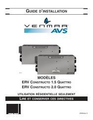
Quattro ERV Installation Manual (07918 rev. C):Constructo ... - Venmar
Quattro ERV Installation Manual (07918 rev. C):Constructo ... - Venmar
Quattro ERV Installation Manual (07918 rev. C):Constructo ... - Venmar

You also want an ePaper? Increase the reach of your titles
YUMPU automatically turns print PDFs into web optimized ePapers that Google loves.
8. AIR FLOW BALANCING<br />
WHAT YOU NEED TO BALANCE THE UNIT<br />
• A magnehelic gauge capable of measuring 0 to 0.5 inch of water (0 to 125 Pa) and<br />
2 plastic tubes.<br />
• The balancing chart provided with the unit.<br />
VP0009<br />
PRELIMINARY STAGES TO BALANCE THE UNIT<br />
• Seal all the unit ductwork with tape. Close all windows and doors.<br />
• Turn off all exhaust devices such as range hood, dryer and bathroom fans.<br />
• Make sure the balancing dampers are fully open.<br />
• Make sure all filters are clean (if it is not the first time you balance the unit).<br />
VD0051<br />
BALANCING PROCEDURE<br />
1. Set the unit to high speed.<br />
Make sure that the furnace blower is ON if the installation is in any way connected to the ductwork of the cold air return. If not, leave<br />
furnace blower OFF. If the outside temperature is below 0°C/32°F, make sure the unit is not running in defrost while balancing.<br />
(By waiting 10 minutes after plugging the unit in, you are assured that the unit is not in a defrost cycle.)<br />
2. Place the magnehelic gauge on a level surface and adjust it to zero.<br />
Fresh air flow<br />
3. Connect tubing from gauge to EXHAUST air flow pressure taps (see diagram).<br />
Be sure to connect the tubes to their appropriate high/low fittings. If the gauge drops below<br />
zero, <strong>rev</strong>erse the tubing connections.<br />
NOTE : It is suggested to start with the exhaust air flow reading because the exhaust has<br />
typically more restrictions than the fresh air, especially in cases of fully ducted<br />
installations or source point ventilation. Place the magnehelic gauge upright and<br />
level. Record equivalent AIR FLOW of the reading according to the balancing chart.<br />
4. Move tubing to FRESH air flow pressure taps (see diagram). Adjust the fresh air balancing<br />
damper until the fresh air flow is approximately the same as the EXHAUST air flow. If fresh<br />
air flow is less than exhaust air flow, then go back and adjust the exhaust balancing damper<br />
to equal the fresh air flow.<br />
VP0010<br />
Exhaust air flow<br />
5. Secure both dampers in place with tape or fastening screw.<br />
6. Write the required air flow information on a label and stick it near the unit for future reference<br />
(date, maximum speed air flows, your name, phone number and business address).<br />
NOTE :The unit is considered balanced even if there is a difference of ± 10 cfm or ± 5 L/s or 17 m³/h<br />
between the two air flows.<br />
VD0052<br />
15