Quattro ERV Installation Manual (07918 rev. C):Constructo ... - Venmar
Quattro ERV Installation Manual (07918 rev. C):Constructo ... - Venmar
Quattro ERV Installation Manual (07918 rev. C):Constructo ... - Venmar

You also want an ePaper? Increase the reach of your titles
YUMPU automatically turns print PDFs into web optimized ePapers that Google loves.
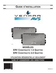
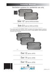
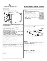
INSTALLATION MANUAL<br />
VB0100<br />
MODELS<br />
<strong>ERV</strong> CONSTRUCTO 1.5 QUATTRO<br />
<strong>ERV</strong> CONSTRUCTO 2.0 QUATTRO<br />
FOR RESIDENTIAL USE ONLY<br />
READ AND SAVE THESE INSTRUCTIONS<br />
<strong>07918</strong> <strong>rev</strong>. C
About this <strong>Manual</strong><br />
This manual uses the following symbols to emphasize particular information:<br />
! WARNING<br />
Identifies an instruction which, if not followed, might cause serious personal injuries including possibility<br />
of death.<br />
CAUTION<br />
Denotes an instruction which, if not followed, may severely damage the unit and/or its components.<br />
NOTE: Indicates additional information needed to fully complete an instruction.<br />
! WARNING<br />
When performing installation, servicing or cleaning the unit, it is recommended to wear safety glasses and gloves.<br />
This unit is intended for residential use only.<br />
CAUTION<br />
TABLE OF CONTENTS<br />
1. S<strong>ERV</strong>ICE . . . . . . . . . . . . . . . . . . . . . . . . . . . . . . . . . . . . . . . . . . . . . . . . . . . . . . . . . . . . . . . . . . .3<br />
1.1 3-D DRAWING . . . . . . . . . . . . . . . . . . . . . . . . . . . . . . . . . . . . . . . . . . . . . . . . . . . . . . . . . . . . . . . . . . . . . . . . . . . . . .3<br />
1.2 S<strong>ERV</strong>ICE PARTS ORDERING CHART . . . . . . . . . . . . . . . . . . . . . . . . . . . . . . . . . . . . . . . . . . . . . . . . . . . . . . . . . . . . . . .3<br />
1.3 TECHNICAL SUPPORT (FOR TECHNICIANS AND/OR CONTRACTORS ONLY) . . . . . . . . . . . . . . . . . . . . . . . . . . . . . . . . . . . . .4<br />
2. TECHNICAL DATA . . . . . . . . . . . . . . . . . . . . . . . . . . . . . . . . . . . . . . . . . . . . . . . . . . . . . . . . . . . .4<br />
2.1 AIR DISTRIBUTION . . . . . . . . . . . . . . . . . . . . . . . . . . . . . . . . . . . . . . . . . . . . . . . . . . . . . . . . . . . . . . . . . . . . . . . . . . .4<br />
2.2 DIMENSIONS . . . . . . . . . . . . . . . . . . . . . . . . . . . . . . . . . . . . . . . . . . . . . . . . . . . . . . . . . . . . . . . . . . . . . . . . . . . . . . . .4<br />
2.3 SPECIFICATIONS . . . . . . . . . . . . . . . . . . . . . . . . . . . . . . . . . . . . . . . . . . . . . . . . . . . . . . . . . . . . . . . . . . . . . . . . . . . . .4<br />
3. DEFROST SETTING VS GEOGRAPHICAL LOCATION . . . . . . . . . . . . . . . . . . . . . . . . . . . . . .5<br />
4. TYPICAL INSTALLATIONS . . . . . . . . . . . . . . . . . . . . . . . . . . . . . . . . . . . . . . . . . . . . . . . . . . . . .5<br />
4.1 FULLY DUCTED SYSTEM . . . . . . . . . . . . . . . . . . . . . . . . . . . . . . . . . . . . . . . . . . . . . . . . . . . . . . . . . . . . . . . . . . . . . . .5<br />
4.2 EXHAUST DUCTED SYSTEM (SOURCE POINT VENTILATION) . . . . . . . . . . . . . . . . . . . . . . . . . . . . . . . . . . . . . . . . . . . . . . .5<br />
4.3 SIMPLIFIED (VOLUME VENTILATION) . . . . . . . . . . . . . . . . . . . . . . . . . . . . . . . . . . . . . . . . . . . . . . . . . . . . . . . . . . . . . . . .6<br />
5. INSTALLATION . . . . . . . . . . . . . . . . . . . . . . . . . . . . . . . . . . . . . . . . . . . . . . . . . . . . . . . . . . . . . .6<br />
5.1 LOCATING AND MOUNTING THE UNIT . . . . . . . . . . . . . . . . . . . . . . . . . . . . . . . . . . . . . . . . . . . . . . . . . . . . . . . . . . . . . .6<br />
5.2 PLANNING THE DUCTWORK . . . . . . . . . . . . . . . . . . . . . . . . . . . . . . . . . . . . . . . . . . . . . . . . . . . . . . . . . . . . . . . . . . . . .7<br />
5.3 CALCULATING DUCT SIZE . . . . . . . . . . . . . . . . . . . . . . . . . . . . . . . . . . . . . . . . . . . . . . . . . . . . . . . . . . . . . . . . . . . . . .7<br />
5.4 INSTALLING THE DUCTWORK AND REGISTERS . . . . . . . . . . . . . . . . . . . . . . . . . . . . . . . . . . . . . . . . . . . . . . . . . . . . . . .8-9<br />
5.5 CONNECTING THE DUCTS TO THE UNIT . . . . . . . . . . . . . . . . . . . . . . . . . . . . . . . . . . . . . . . . . . . . . . . . . . . . . . . . . . . .10<br />
5.6 INSTALLING THE EXTERIOR HOODS . . . . . . . . . . . . . . . . . . . . . . . . . . . . . . . . . . . . . . . . . . . . . . . . . . . . . . . . . . . . . . .11<br />
6. CONTROLS . . . . . . . . . . . . . . . . . . . . . . . . . . . . . . . . . . . . . . . . . . . . . . . . . . . . . . . . . . . . . . . .12<br />
6.1 MAIN CONTROLS . . . . . . . . . . . . . . . . . . . . . . . . . . . . . . . . . . . . . . . . . . . . . . . . . . . . . . . . . . . . . . . . . . . . . . . . . . .12<br />
6.2 AUXILIARY CONTROLS . . . . . . . . . . . . . . . . . . . . . . . . . . . . . . . . . . . . . . . . . . . . . . . . . . . . . . . . . . . . . . . . . . . . . . . .12<br />
6.3 ELECTRICAL CONNECTION TO LITE-TOUCH CONSTRUCTO AND AUXILIARY CONTROLS . . . . . . . . . . . . . . . . . . . . . . . . . . .13<br />
6.4 ELECTRICAL CONNECTION TO THE FURNACE (OPTIONAL) . . . . . . . . . . . . . . . . . . . . . . . . . . . . . . . . . . . . . . . . . . . . . . .13<br />
7. WIRING DIAGRAM . . . . . . . . . . . . . . . . . . . . . . . . . . . . . . . . . . . . . . . . . . . . . . . . . . . . . . . . . .14<br />
8. AIR FLOW BALANCING . . . . . . . . . . . . . . . . . . . . . . . . . . . . . . . . . . . . . . . . . . . . . . . . . . . . . .15<br />
9. TROUBLESHOOTING . . . . . . . . . . . . . . . . . . . . . . . . . . . . . . . . . . . . . . . . . . . . . . . . . . . . . . . .16<br />
2
1. S<strong>ERV</strong>ICE<br />
1.1 3D DRAWING<br />
1<br />
2<br />
16<br />
17<br />
15<br />
10<br />
3<br />
8<br />
4<br />
7<br />
9<br />
14<br />
6<br />
10<br />
5<br />
11<br />
4<br />
12<br />
VL0027<br />
13<br />
1.2 S<strong>ERV</strong>ICE PARTS ORDERING CHART<br />
No. Description CONSTRUCTO 1.5 QUATTRO CONSTRUCTO 2.0 QUATTRO<br />
43115 45115<br />
1 Electronic Board & Spacers (kit) 16585 16585<br />
2 Door Switch (SPST), E69 10A 01825 01825<br />
3 Double Collar Port No. 2 02257 02257<br />
4 Damper Rod (kit) 13037 13037<br />
5 Damper No. 1 (kit) 12454 12454<br />
6 Switch 12664 12664<br />
7 Door Latches & Screws<br />
00886 (2) 00886 (2)<br />
00601 (4) 00601 (4)<br />
8 Thermistor (kit) 12895 12895<br />
9 Damper Actuator Assembly 13734 13734<br />
10 Basic Filter 02300 02300<br />
11 Square Damper (kit) 13033 13033<br />
12 Blower Assembly 16580 16581<br />
13 Door Latches (Keeper) & Screws<br />
00887 (2) 00887 (2)<br />
00601 (4) 00601 (4)<br />
14 Door Assembly (including 13) 16584 16584<br />
15 Energy Recovery Core 16582 16582<br />
16 Balancing Double Collar Port 02256 02256<br />
17 Balancing Damper 02253 02253<br />
Please take note that parts not listed are not available; those parts require assembly knowledge that only manufacturer can guarantee.<br />
TO ORDER PARTS: CONTACT YOUR LOCAL DISTRIBUTOR.<br />
3
1. S<strong>ERV</strong>ICE (CONT’D)<br />
1.3 TECHNICAL SUPPORT (FOR TECHNICIANS AND/OR CONTRACTORS ONLY)<br />
For assistance, call on weekdays from 8:30 AM to 5:00 PM (Eastern Standard Time).<br />
NOTE: Do not call this number to order parts.<br />
Canada & USA: 1-800-649-0372 (toll-free)<br />
2. TECHNICAL DATA<br />
2.1 AIR DISTRIBUTION<br />
NORMAL OPERATION<br />
DEFROST MODE<br />
STALE AIR<br />
TO OUTSIDE<br />
FRESH AIR<br />
TO BUILDING<br />
FILTERED AIR<br />
TO BUILDING<br />
VF0041<br />
FRESH AIR<br />
FROM OUTSIDE<br />
STALE AIR<br />
FROM BUILDING<br />
VF0040<br />
STALE AIR<br />
FROM BUILDING<br />
Outside Temperature Defrost Cycles Extended Defrost Cycles*<br />
Celsius (°C)<br />
-5<br />
-15<br />
-27<br />
Fahrenheit (°F)<br />
23<br />
5<br />
-17<br />
Defrosting (min.)<br />
10<br />
10<br />
10<br />
Operation time (min.)<br />
between each defrost cycle<br />
60<br />
30<br />
20<br />
Defrosting (min.)<br />
*IN A COLD REGION, SET-UP EXTENDED DEFROST BY REMOVING JUMPER JU1-F ON THE CIRCUIT BOARD.<br />
10<br />
10<br />
10<br />
Operation time (min.)<br />
between each defrost cycle<br />
NOTE: THE <strong>ERV</strong> CONSTRUCTO 1.5 QUATTRO AND <strong>ERV</strong> CONTRUCTO 2.0 QUATTRO PERFORMANCE CHARTS ARE LISTED<br />
ON THE SPECIFICATION SHEETS OF THESE UNITS. VISIT OUR WEBSITE AT WWW.VENMAR.CA TO ACCESS THOSE DOCUMENTS.<br />
30<br />
20<br />
15<br />
2.2 DIMENSIONS<br />
16½”<br />
(419 mm)<br />
17¼” (438 mm)<br />
Electrical<br />
Compartment<br />
Power Cord<br />
36” (914 mm)<br />
High speed/Remote/Low speed<br />
Switch<br />
Blower<br />
Access Door Assembly<br />
39” (991 mm)<br />
34” (864 mm)<br />
18”<br />
(457 mm)<br />
VK0059A<br />
6”<br />
(152 mm)<br />
Damper<br />
Actuator<br />
2¼”<br />
(57 mm)<br />
2.3 SPECIFICATIONS<br />
MODEL<br />
WIDTH<br />
HEIGHT<br />
DEPTH<br />
WEIGHT<br />
ELECTRICAL SUPPLY<br />
POWER CONSUMPTION<br />
CONSTRUCTO 1.5 QUATTRO<br />
34’’ (864 MM)<br />
16½’’ (419 MM)<br />
17¼’’ (438 MM)<br />
74 LB (34 KG)<br />
120 V, 60 HZ<br />
115 W<br />
CONSTRUCTO 2.0 QUATTRO<br />
34” (864 MM)<br />
16½’’ (419 MM)<br />
17¼’’ (438 MM)<br />
76 LB (35 KG)<br />
120 V, 60 HZ<br />
240 W<br />
4
3. DEFROST SETTING VS GEOGRAPHICAL LOCATION<br />
YELLOWKNIFE<br />
ANCHORAGE<br />
WHITEHORSE<br />
JUNEAU<br />
HAY RIVER<br />
FORT SMIT H<br />
FORT MCMURRAY<br />
ZONE A<br />
GRANDE PRAIRIE<br />
Prince Rupert<br />
EDMONTON<br />
GOOSE BAY<br />
JASPER<br />
PRINCE ALBERT<br />
LABRADOR CITY<br />
KAMLOOP S<br />
SASKATOON<br />
CALGARY<br />
REGINA WINNIPEG<br />
CHIBOUGAMAU<br />
SEPT-ILES<br />
PENTICTON<br />
LETHBRIDGE<br />
VICTORIA<br />
TIMMINS<br />
CHICOUTIMI<br />
GASPÉ<br />
VAL-DOR MATANE<br />
BATHURST<br />
HELENA<br />
QUÉBEC<br />
OLYMPIA<br />
SUDBURY<br />
BISMARCK SAULT STE MARIE<br />
NORTH BAY<br />
CHARLOTTETOWN<br />
ST. PAUL<br />
MONTRÉAL<br />
ST JOHN'S<br />
OTTAWA ST-JOHN<br />
SALEM<br />
TORONTO<br />
HALIFAX<br />
ZONE B<br />
MADISON<br />
BOISE<br />
DETROIT<br />
DES MOINES<br />
BOSTON<br />
SALT LAKE CITY<br />
DENVER<br />
INDIANAPOLIS HARRISBURGHARTFORD<br />
RENO<br />
SPRINGFIELD COLUMBUS<br />
SACRAMENTO<br />
TOPEKA<br />
WASHINGTON<br />
SANTA FE<br />
OKLAHOMA CITY<br />
NASHVILLE<br />
RALEIGH<br />
PHOENIX<br />
ATLANTA<br />
COLUMBIA<br />
VN0007<br />
ZONE A: SET EXTENDED DEFROST BY REMOVING JUMPER JU1-F<br />
ON THE MAIN CIRCUIT BOARD INSIDE THE ELECTRICAL<br />
COMPARTMENT.<br />
ZONE B: EXTENDED DEFROST SETTING NOT REQUIRED<br />
(FACTORY DEFROST STRATEGY PRE-SET).<br />
AUSTIN<br />
BATON ROUGE<br />
4. TYPICAL INSTALLATIONS<br />
There are three (3) common installation methods.<br />
4.1 FULLY DUCTED SYSTEM<br />
(Primarily for homes with radiant hot water or electric baseboard heating. See Figure 1.)<br />
Moist, stale air is exhausted from the high humidity areas in the home, such as bathrooms,<br />
kitchen and laundry room. Fresh air is supplied to bedrooms and principal living areas.<br />
If required, bathroom fans and a range hood may be used to better exhaust stale air.<br />
Homes with more than one level require at least one exhaust register at the highest level.<br />
4.2 EXHAUST DUCTED SYSTEM (SOURCE POINT VENTILATION)<br />
(For homes with forced air heating. See Figure 2.)<br />
Moist, stale air is exhausted from the high humidity areas in the home, such as<br />
bathrooms, kitchen and laundry room. Fresh air is supplied through the cold air return or<br />
the supply duct of the furnace. If required, bathroom fans and a range hood may be used<br />
to better exhaust stale air.<br />
Homes with more than one level require at least one exhaust register at the highest level.<br />
VH0002<br />
FIGURE 1<br />
See 5.4.1<br />
for details<br />
NOTE:<br />
For this type of installation, it is not essential that the furnace blower runs when<br />
the unit is in operation, but we recommend it.<br />
5<br />
VH0006<br />
FIGURE 2<br />
See 5.4.2<br />
for details
4. TYPICAL INSTALLATIONS (CONT’D)<br />
4.3 SIMPLIFIED (VOLUME VENTILATION)<br />
(For homes with forced air heating. See Figure 3.)<br />
Fresh air and exhaust air flow through the furnace ducts which simplifies the installation.<br />
The use of bathroom fans and range hood is suggested to exhaust stale air.<br />
NOTE:<br />
For this type of installation, the furnace blower should be running when the<br />
unit is in operation.<br />
VH0007<br />
FIGURE 3<br />
See 5.4.3<br />
for details<br />
5. INSTALLATION<br />
! WARNING<br />
When applicable local regulations comprises more restrictive installation and/or certification requirements, the<br />
aforementioned requirements p<strong>rev</strong>ail on those of this document and the installer agrees to conform to these at<br />
his own expenses.<br />
! WARNING<br />
When performing installation, servicing or cleaning the unit, it is recommended to wear safety glasses and gloves.<br />
INSPECT THE CONTENTS OF THE BOX<br />
• Inspect the exterior of the unit for shipping damage. Ensure that there is no damage to the door, door latches, door hinges,<br />
dampers, duct collars, cabinet, etc.<br />
• Inspect the interior of the unit for damage. Ensure that the fan motor assembly, energy recovery core, insulation, dampers and<br />
damper actuator are all intact.<br />
• If the unit was damaged during shipping, contact your local distributor. (Claim must be made within 24 hours after delivery.)<br />
• Use checklist included with the unit to ensure that no parts are missing.<br />
5.1 LOCATING AND MOUNTING THE UNIT<br />
Choose an appropriate location for the unit:<br />
• Within an area of the house where the temperature is above 10°C/50°F (basement, attic, furnace room, laundry room, etc.).<br />
• Away from living areas (dining room, living room, bedroom), if possible.<br />
• So as to provide easy access to the interior cabinet and to the control panel on the side of the unit.<br />
• Close to an exterior wall, so as to limit the length of the insulated flexible duct to and from the unit.<br />
• Away from hot chimneys, electrical panel and other fire hazards.<br />
• Allow for a power source (standard outlet).<br />
Hang the unit with the 4 chains and springs provided (see<br />
Figures 4 and 5).<br />
VD0037<br />
FIGURE 4<br />
VD0038<br />
FIGURE 5<br />
CAUTION<br />
Make sure the unit is level, with 1/8’’ (3 mm) tilt backwards (see Figure 6).<br />
1/8”<br />
(3 mm)<br />
6<br />
VD0039A<br />
FIGURE 6
5. INSTALLATION (CONT’D)<br />
5.2 PLANNING THE DUCTWORK<br />
a) Follow the instructions in Section 5.3 to determine the appropriate duct diameters for your system.<br />
b) Keep it simple. Plan for a minimum number of bends and joints. Keep the length of insulated duct to a minimum.<br />
c) Do not use wall cavities as ducts. Do not use branch lines smaller than 4” (102 mm) Ø.<br />
d) Do not ventilate crawl spaces or cold rooms. Do not attempt to recover the exhaust air from a dryer or a range hood. This would<br />
cause clogging of the recovery core. Use sheet metal for the kitchen exhaust duct.<br />
e) Be sure to plan for at least one exhaust register on the highest lived-in level of the house if it has 2 floors or more.<br />
5.3 CALCULATING THE DUCT SIZE<br />
Use the table below to ensure that the ducts you intend to install will be carrying air flows at or under the recommended values.<br />
Avoid installing ducts that will have to carry air flows near the maximum values and never install a duct if its air flow exceeds<br />
the maximum value.<br />
Duct Recommended Maximum<br />
Diameter Air Flow Air Flow<br />
4” (102 mm) 40 cfm 19 l/s 68 m³/h 60 cfm 28 l/s 102 m³/h<br />
5” (127 mm) 75 cfm 35 l/s 127 m³/h 110 cfm 52 l/s 187 m³/h<br />
6” (152 mm) 120 cfm 57 l/s 204 m³/h 180 cfm 85 l/s 306 m³/h<br />
7” (178 mm) 185 cfm 87 l/s 314 m³/h 270 cfm 127 l/s 459 m³/h<br />
8” (203 mm) 260 cfm 123 l/s 442 m³/h 380 cfm 179 l/s 645 m³/h<br />
END<br />
BRANCHES<br />
5" Ø<br />
70 CFM<br />
NOTE: Examples 5.3.1 and 5.3.2 use imperial measures.<br />
The same calculation applies to metric measures.<br />
5.3.1 Example of calculation:<br />
Problem: My installation requires two exhaust registers (one for the kitchen, one for the bathroom). I will connect these registers<br />
to a main duct which will connect to the unit (high speed performance value of 140 cfm). What size of duct should I use for the<br />
main exhaust duct and for the two end branches leading to the registers? (See Figure 7.)<br />
Solution: Simplified method. (For a more detailed method of calculating duct size refer to the ASHRAE or HRAI HANDBOOK).<br />
Main duct: Table above indicates a 6” Ø duct: recommended air flow: 120 cfm; maximum air flow: 180 cfm. The high speed air<br />
flow of 140 cfm is close enough to the recommended value (120) and far enough from the maximum value (180). Therefore a<br />
6” Ø duct or larger is an appropriate choice for the main exhaust duct.<br />
End branches: Each end branch will have to transport air flow of 70 cfm (140 divided by 2). Table above indicates a 5” Ø duct :<br />
recommended air flow : 75 cfm; maximum air flow : 110 cfm. The high speed air flow of 70 cfm is close enough to the<br />
recommended value (75) and far enough from the maximum value (110). Therefore, a 5” Ø duct or larger is an appropriate choice<br />
for the 2 end branches.<br />
NOTE : A 4” Ø duct would have been too small because the maximum acceptable value for a 4” Ø duct is 60 cfm.<br />
5.3.2 Example of a design for a fully ducted system for a unit having 222 cfm high speed performance (See Figure 8).<br />
VI0003<br />
FIGURE 7<br />
MAIN BRANCH<br />
6" Ø 140 CFM<br />
5”<br />
5” Ø<br />
65 CFM<br />
6” Ø<br />
129 CFM<br />
6” Ø<br />
93 CFM<br />
5” Ø<br />
64 CFM<br />
6”<br />
4”<br />
4”<br />
4” Ø<br />
42 CFM<br />
6”<br />
4”<br />
7” 7”<br />
4” Ø 42 CFM<br />
4”<br />
6” Ø 84 CFM<br />
6”<br />
6” Ø 96 CFM<br />
6”<br />
6” Ø 138 CFM<br />
VI0004<br />
7” Ø 222 CFM<br />
FIGURE 8<br />
7” Ø 222 CFM<br />
7
5. INSTALLATION (CONT’D)<br />
5.4 INSTALLING THE DUCTWORK AND REGISTERS<br />
0 ! WARNING<br />
Never install a stale air exhaust register in a room where there is a combustion device, such as a gas furnace, a<br />
gas water heater or a fireplace.<br />
CAUTION<br />
The ductwork is intended to be installed in compliance with all local and national codes that are applicable.<br />
5.4.1 Fully Ducted System (as illustrated in Section 4.1)<br />
Stale air exhaust ductwork:<br />
• Install registers in areas where contaminants are produced: kitchen, bathrooms, laundry room, etc.<br />
• Install registers 6 to 12 inches (152 to 305 mm) from the ceiling on an interior wall OR install them in the ceiling.<br />
• Install the kitchen register at least 4 feet (1.2 m) from the range.<br />
• If possible, measure the velocity of the air flowing through the registers. If the velocity is higher than 400 ft./min. (122 m/min.),<br />
then the register type is too small. Replace with a larger one.<br />
Fresh air distribution ductwork:<br />
• Install registers in bedrooms, dining room, living room and basement.<br />
• Install registers either in the ceiling or high on the walls with air flow directed towards the ceiling.<br />
(The cooler air will then cross the upper part of the room and mix with room air before descending to occupant level.)<br />
• If a register must be floor installed, direct the air flow up the wall.<br />
5.4.2 Exhaust Ducted System (Source Point Ventilation) (as illustrated in Section 4.2)<br />
Stale air exhaust ductwork: (same as for Fully Ducted System described in 5.4.1)<br />
Fresh air distribution:<br />
0 ! WARNING<br />
When performing duct connection to the furnace, installation must be done in accordance with all applicable<br />
codes and standards. Please refer to your local building code.<br />
CAUTION<br />
When performing duct connection to the furnace supply duct, this duct must be sized to support the additional<br />
airflow produced by the <strong>ERV</strong>. Also, use a metal duct. It is recommended that the <strong>ERV</strong> is running when the furnace<br />
is in operation in order to p<strong>rev</strong>ent backdrafting inside <strong>ERV</strong>.<br />
There are two methods for connecting the unit to the furnace:<br />
Method 1: supply side connection<br />
• Cut an opening into the furnace supply duct at least 18 inches (0.5 m) from<br />
the furnace.<br />
• Connect this opening to the fresh air distribution port of the <strong>ERV</strong> (use metal<br />
duct, see Figure 9).<br />
• Make sure that the <strong>ERV</strong> duct forms an elbow inside the furnace ductwork.<br />
• If desired, interlock (synchronize) the furnace blower operation with the <strong>ERV</strong><br />
operation. (See Section 6.4).<br />
Metal duct<br />
Minimum<br />
18” (0.5 m)<br />
VD0172<br />
FIGURE 9<br />
Method 2: return side connection<br />
• Cut an opening into the furnace return duct not less than 10 feet (3.1m) from<br />
the furnace (A+B).<br />
• Connect this opening to the fresh air distribution port of the <strong>ERV</strong> (see Figure 10).<br />
NOTE: For Method 2, it is not essential that the furnace blower runs when the unit<br />
is in operation, but we recommend it. If desired, synchronize the furnace<br />
blower operation with the <strong>ERV</strong> operation (see Section 6.4).<br />
8<br />
VD0108<br />
A<br />
A+B = not less<br />
than 10’ (3.1 m)<br />
FIGURE 10<br />
B
5. INSTALLATION (CONT’D)<br />
5.4 INSTALLING THE DUCTWORK AND REGISTERS (CONT’D)<br />
5.4.3 Simplified <strong>Installation</strong> (Volume Ventilation) (as illustrated in Section 4.3)<br />
0 !<br />
WARNING<br />
When performing duct connection to the furnace, installation must be done in accordance with all applicable<br />
codes and standards. Please refer to your local building code.<br />
CAUTION<br />
When performing duct connection to the furnace ducts (Method 1), these ducts must be sized to support the additional<br />
airflow produced by the <strong>ERV</strong>. Also, the supply duct must be a metal duct. It is recommended that the <strong>ERV</strong> runs<br />
when the furnace is in operation in order to p<strong>rev</strong>ent backdrafting inside <strong>ERV</strong>.<br />
There are two methods (Figures 11 and 12) for connecting the unit to the furnace:<br />
Method 1: return-supply<br />
Method 2: return-return<br />
Metal duct<br />
Minimum 18”<br />
(0.5 m)<br />
A<br />
A<br />
B<br />
VD0171<br />
FIGURE 11<br />
A+B = not less<br />
than 10’ (3.1 m)<br />
B<br />
Stale air intake:<br />
• Cut an opening into the furnace return duct (not less than 10 feet (3.1 m) from the furnace).<br />
• Connect this opening to the stale air intake port on the <strong>ERV</strong> as shown.<br />
Fresh air distribution: (same instructions as for Method 1 or Method 2, Section 5.4.2).<br />
CAUTION<br />
If using Method 2, make sure the furnace blower operation is synchronized with the unit operation! See Section 6.4.<br />
VD0111<br />
Minimum 3’<br />
(0.9 m)<br />
FIGURE 12<br />
A+B = not less<br />
than 10’ (3.1 m)<br />
For Method 2 (return-return) make sure there is a distance of at least 3 feet (0.9 m) between the 2 connections to the furnace.<br />
NOTE: For Method 1, it is not essential to synchronize the furnace blower operation with the unit operation, but we<br />
recommend it.<br />
9
5. INSTALLATION (CONT’D)<br />
5.5 CONNECTING THE DUCTS TO THE UNIT<br />
Insulated flexible ducts<br />
Use the following procedure to connect the insulated flexible ducts to the ports on the unit (exhaust to outside and fresh air from outside).<br />
a) Pull back the insulation to expose the flexible duct.<br />
b) Connect the interior flexible duct to the port using a duct tie.<br />
c) Carefully seal the connection with duct tape.<br />
d) Pull the insulation over the joint and tuck it between the inner and outer rings of the double collar.<br />
e) Pull the vapor barrier over the insulation and over the outer ring of the double collar.<br />
f) Apply duct tape to the joint making an airtight seal. Avoid compressing the insulation when you pull the tape tightly around the joint.<br />
Compressed insulation loses its R value and causes water dripping due to condensation on the exterior surface of the duct.<br />
CAUTION<br />
Make sure that the vapor barrier on the insulated ducts does not tear during installation to avoid condensation<br />
within the duct.<br />
a) b) c) d), e) f)<br />
VJ0001<br />
VJ0002<br />
VJ0003 VJ0004 VJ0005<br />
Rigid ducts :<br />
Use duct tape to connect the rigid ducts to the ports.<br />
Make sure that the 2 balancing dampers are left in a fully open position before connecting the ducts to these ports (fresh air distribution<br />
port and stale air exhaust port as shown on Figure 13).<br />
CAUTION<br />
Do not use screws to connect rigid ducts to the ports.<br />
VJ0011<br />
FIGURE 13<br />
10
5. INSTALLATION (CONT’D)<br />
5.6 INSTALLING THE EXTERIOR HOODS<br />
Choose an appropriate location for installing the exterior hoods:<br />
• a minimum distance of 6 feet (1.8 m) between the hoods is necessary to avoid cross-contamination<br />
• a minimum distance of 18 inches (457 mm) from the ground is required<br />
Make sure the intake hood is at least 6 feet (1.8 m) away from any of the following :<br />
• dryer exhaust, high efficiency furnace vent, central vacuum vent<br />
• gas meter exhaust, gas barbecue-grill<br />
• any exhaust from a combustion source<br />
• garbage bin and any other source of contamination<br />
Refer to Figure 14 for connecting the insulated duct to the hoods. Place the “ FRESH AIR INTAKE ” sticker, provided in the installation<br />
kit, on corresponding hood. An “ Anti-Gust Intake Hood ” should be installed in regions where a lot of snow is expected to fall.<br />
Exhaust<br />
hood<br />
18”<br />
(457 mm)<br />
6’<br />
(1.8 m)<br />
Intake<br />
hood<br />
6ӯ<br />
(152 mm)<br />
18”<br />
(457 mm)<br />
6’<br />
(1.8 m)<br />
Optional duct<br />
location<br />
18”<br />
(457 mm)<br />
Tape and duct tie<br />
VD0028<br />
FIGURE 14<br />
11
6. CONTROLS<br />
6.1 MAIN CONTROLS<br />
6.1.1 3-Position Switch<br />
Location: Located on the side of the unit.<br />
Purpose: To adjust air supply.<br />
How to operate on a daily basis<br />
• Select LOW SPEED for normal daily operation.<br />
• Select HIGH SPEED for excess pollutants and humidity (parties, odors, smoke, etc.)<br />
How to turn off the unit :<br />
Set switch to the REMOTE position.<br />
! WARNING<br />
Optional controls can still activate the unit, even when in REMOTE position.<br />
You must, therefore, unplug the unit to be absolutely sure it is off.<br />
VC0091<br />
6.1.2 Lite-Touch <strong>Constructo</strong><br />
Location: Located in the busiest area of the house.<br />
Purpose: To adjust air supply and select the desired indoor humidity level.<br />
Activate the push-button. The color of the indicator shows the unit operating mode.<br />
Color Mode Suggested Use<br />
Green Intermittent Select this mode when you are away from the house for a few days. Also, when<br />
you deem the inside air is too dry in heating season, or too humid in cooling<br />
season. In this mode, the unit is OFF for 40 minutes per hour and ventilates at<br />
minimum speed the remaining 20 minutes of the hour.<br />
Yellow Min. Speed For normal daily operation.<br />
Ventilation<br />
Red Max. Speed For excess pollutants and humidity (parties, odors, smoke, etc.).<br />
Ventilation<br />
6.2 AUXILIARY CONTROLS<br />
6.2.1 20-Minute Lighted Push-Button<br />
VC0075<br />
MAX<br />
MIN<br />
INTERMITTENT<br />
L-T<br />
Location:<br />
Purpose:<br />
Located in the bathroom or in other locations where temporary humidity excess or pollutants<br />
are present.<br />
To eliminate excess humidity produced by showers or other periodic activities<br />
generating pollutants.<br />
ON<br />
Press once to activate the push-button. The unit will operate at high speed for 20 minutes and the indicator will<br />
light up. To stop activation before the end of the 20-minute cycle, push one more time. The unit will return<br />
to its p<strong>rev</strong>ious setting.<br />
VC0082<br />
6.2.2 60-Minute Mechanical Timer<br />
Location:<br />
Purpose:<br />
Located in the bathroom or in other locations where temporary humidity excess or pollutants<br />
are present.<br />
To eliminate excess humidity produced by showers or other periodic activities<br />
generating pollutants.<br />
TURN<br />
PAST<br />
20<br />
OFF<br />
10<br />
20<br />
30<br />
This control activates the system to operate at high speed for periods varying from 10 to 60 minutes.<br />
60<br />
40<br />
50<br />
12<br />
VC0017
6. CONTROLS (CONT’D)<br />
6.3 ELECTRICAL CONNECTION TO LITE-TOUCH CONSTRUCTO AND AUXILIARY CONTROLS<br />
MAIN CONTROL<br />
LITE-TOUCH CONSTRUCTO<br />
CONNECTION<br />
B<br />
G<br />
Y<br />
B<br />
G<br />
AUXILIARY CONTROLS CONNECTION<br />
(OL AND OC FOR TIMER, OL, OC<br />
AND I FOR LIGHTED PUSH-BUTTON)<br />
VE0116<br />
OL<br />
OC<br />
I<br />
6.4 ELECTRICAL CONNECTION TO THE FURNACE (OPTIONAL)<br />
! WARNING<br />
Never connect a 120-volt AC circuit to the terminals of the furnace interlock (standard wiring). Only use the<br />
low-voltage class 2 circuit of the furnace blower control.<br />
4 WIRES<br />
2 WIRES<br />
(heating only)<br />
W<br />
R<br />
G<br />
C<br />
Y<br />
W R G Y<br />
THERMOSTAT<br />
TERMINAL<br />
wiring<br />
nuts<br />
RED<br />
GREEN<br />
BLUE<br />
NC<br />
NO<br />
COM<br />
*FURNACE INTERLOCK<br />
RELAY<br />
Unit Control Module<br />
9-PIN AMP PLUG<br />
J1<br />
1<br />
2<br />
3<br />
4<br />
5<br />
6<br />
7<br />
8<br />
9<br />
GRAY<br />
BROWN<br />
FURNACE<br />
24-VOLT<br />
TERMINAL BLOCK<br />
2 WIRES<br />
COOLING SYSTEM<br />
VE0009A *FURNACE INTERLOCK RELAY, PART NO. 12658<br />
13
NEUTRAL<br />
J1 2<br />
SPDT SWITCH (ON-OFF-ON)<br />
S2<br />
120 V, 60 Hz<br />
FROM MAIN<br />
NOTE 1<br />
BK BK TO R = LOW SPEED EXCHANGE<br />
G<br />
BK TO G = HIGH SPEED EXCHANGE<br />
R<br />
NO CONNECTION = OFF<br />
J1 1<br />
J1 8<br />
1<br />
2<br />
3<br />
1<br />
2<br />
3<br />
7. WIRING DIAGRAM<br />
0 ! WARNING<br />
Risk of electrical shocks. Before performing any maintenance or servicing, always disconnect the unit from its<br />
power source. This product employs overload protection (fuse). A blown fuse indicates an overload or short-circuit<br />
situation. If the fuse blows, unplug the product from the outlet. Replace the fuse as per the servicing instructions<br />
(follow product marking for proper fuse rating) and check the product. If the replacement fuse blows, a short-circuit<br />
may be present and the product should be discarded or returned to an authorized service facility for examination<br />
and/or repair.<br />
S1<br />
A1<br />
FAN<br />
MOTOR<br />
NC MED<br />
HIGH<br />
OPTIONAL<br />
NOTE 6<br />
OVERRIDE SWITCH<br />
OVERRIDE SWITCH<br />
OVERRIDE LED<br />
J1 6<br />
J1 4<br />
J1 3<br />
LOW<br />
K2<br />
RELAY<br />
K1<br />
RELAY<br />
-17˚F<br />
-27˚C<br />
Connection<br />
Models : <strong>ERV</strong> <strong>Constructo</strong> 1.5 <strong>Quattro</strong><br />
<strong>ERV</strong> <strong>Constructo</strong> 2.0 <strong>Quattro</strong><br />
Logic<br />
M1<br />
NOTE 4<br />
M2<br />
DAMPER<br />
MOTOR<br />
J1 9<br />
K5<br />
RELAY<br />
X1 M1<br />
GY GY NEUTRAL<br />
O O HIGH<br />
G G FAN MOTOR<br />
NC R BL R MEDIUM<br />
LOW<br />
NOTE 2<br />
A 1<br />
2<br />
1<br />
B<br />
G<br />
C1<br />
BN<br />
BN<br />
R<br />
DEFROST<br />
TEMPERATURE<br />
SENSOR<br />
Y<br />
F F IOCOL<br />
3 4 5 7 8 9<br />
ABCDEFG<br />
-t˚<br />
J4<br />
R 1<br />
J3<br />
T 1<br />
ELECTRONIC ASSEMBLY<br />
GY<br />
R<br />
4<br />
7<br />
FAN<br />
FURNACE<br />
INTERLOCK<br />
KIT<br />
BN<br />
14<br />
J1<br />
3 2 1<br />
GY<br />
NOTES<br />
BL<br />
Y<br />
5, 6<br />
MODEL<br />
O 23˚F -5˚C 5˚F<br />
-15˚C<br />
M2<br />
6<br />
9<br />
BK<br />
W<br />
ELECTRONIC ASSEMBLY<br />
DAMPER MOTOR<br />
X2<br />
Y BL<br />
BL BL<br />
G G<br />
LINE VOLTAGE<br />
LOW VOLTAGE<br />
AND FIELD WIRING<br />
COLOR CODE<br />
FUNCTION TABLE RELAY<br />
K5<br />
K2<br />
K1<br />
MODE<br />
Intermittent<br />
Exchange Low<br />
Exchange High<br />
Defrost Cycle<br />
Off<br />
MAIN EARTHING<br />
POINT<br />
NC<br />
O<br />
R<br />
W<br />
W1<br />
G<br />
NO CONNECTION<br />
ORANGE<br />
RED<br />
WHITE<br />
YELLOW<br />
Y<br />
BLACK<br />
BLUE<br />
BROWN<br />
GREEN<br />
GRAY<br />
BK<br />
BL<br />
BN<br />
G<br />
GY<br />
120V 60 Hz<br />
W<br />
BK<br />
0 = Relay coil is de-energized<br />
1 = Relay coil is energized<br />
NEUTRAL<br />
LINE F1<br />
NOTE 7<br />
1<br />
0<br />
0<br />
1<br />
1<br />
0<br />
0<br />
1<br />
1<br />
0<br />
0<br />
1<br />
1<br />
1<br />
0<br />
NEMA-15P<br />
5-15 PLUG<br />
W<br />
COM NO<br />
BK BK<br />
DOOR INTERLOCK<br />
SWITCH<br />
S1<br />
NOTES<br />
5. FIELD INSTALLED OPTION: USE ONLY<br />
FACTORY-SUPPLIED KIT NO. 12658. FURNACE FAN<br />
CIRCUIT MUST BE CLASS 2 CIRCUIT ONLY.<br />
6. FIELD WIRING MUST COMPLY WITH APPLICABLE<br />
CODES, ORDINANCES AND REGULATIONS.<br />
7. SPECIFIED UL LISTED/CSA CERTIFIED LINE FUSE.<br />
LITTELFUSE (225 003), 2AG FAST-ACTING FUSE,<br />
224/225 SERIES<br />
RATING: 3 A.<br />
1. OPTIONAL CONTROLS AVAILABLE.<br />
2. FACTORY SET WIRING FOR BLOWER SPEED<br />
SELECTION IS HIGH AND LOW. MEDIUM SPEED CAN<br />
BE SELECTED INSTEAD OF LOW SPEED. DISCONNECT<br />
RED WIRE FROM THE MOTOR RED TAP AND CONNECT<br />
TO THE MOTOR BLUE TAP.<br />
3. IF ANY OF THE ORIGINAL WIRE, AS SUPPLIED, MUST<br />
BE REPLACED, USE THE SAME OR EQUIVALENT WIRE.<br />
4. USE FACTORY-SUPPLIED PROTECTIVE TUBING.<br />
VE0141A
8. AIR FLOW BALANCING<br />
WHAT YOU NEED TO BALANCE THE UNIT<br />
• A magnehelic gauge capable of measuring 0 to 0.5 inch of water (0 to 125 Pa) and<br />
2 plastic tubes.<br />
• The balancing chart provided with the unit.<br />
VP0009<br />
PRELIMINARY STAGES TO BALANCE THE UNIT<br />
• Seal all the unit ductwork with tape. Close all windows and doors.<br />
• Turn off all exhaust devices such as range hood, dryer and bathroom fans.<br />
• Make sure the balancing dampers are fully open.<br />
• Make sure all filters are clean (if it is not the first time you balance the unit).<br />
VD0051<br />
BALANCING PROCEDURE<br />
1. Set the unit to high speed.<br />
Make sure that the furnace blower is ON if the installation is in any way connected to the ductwork of the cold air return. If not, leave<br />
furnace blower OFF. If the outside temperature is below 0°C/32°F, make sure the unit is not running in defrost while balancing.<br />
(By waiting 10 minutes after plugging the unit in, you are assured that the unit is not in a defrost cycle.)<br />
2. Place the magnehelic gauge on a level surface and adjust it to zero.<br />
Fresh air flow<br />
3. Connect tubing from gauge to EXHAUST air flow pressure taps (see diagram).<br />
Be sure to connect the tubes to their appropriate high/low fittings. If the gauge drops below<br />
zero, <strong>rev</strong>erse the tubing connections.<br />
NOTE : It is suggested to start with the exhaust air flow reading because the exhaust has<br />
typically more restrictions than the fresh air, especially in cases of fully ducted<br />
installations or source point ventilation. Place the magnehelic gauge upright and<br />
level. Record equivalent AIR FLOW of the reading according to the balancing chart.<br />
4. Move tubing to FRESH air flow pressure taps (see diagram). Adjust the fresh air balancing<br />
damper until the fresh air flow is approximately the same as the EXHAUST air flow. If fresh<br />
air flow is less than exhaust air flow, then go back and adjust the exhaust balancing damper<br />
to equal the fresh air flow.<br />
VP0010<br />
Exhaust air flow<br />
5. Secure both dampers in place with tape or fastening screw.<br />
6. Write the required air flow information on a label and stick it near the unit for future reference<br />
(date, maximum speed air flows, your name, phone number and business address).<br />
NOTE :The unit is considered balanced even if there is a difference of ± 10 cfm or ± 5 L/s or 17 m³/h<br />
between the two air flows.<br />
VD0052<br />
15
9. TROUBLESHOOTING<br />
NOTE : Be sure to unplug and inspect the unit before proceeding with these steps.<br />
Start with point 1, then point 2 and so on.<br />
PROBLEMS POSSIBLES CAUSES YOU SHOULD TRY THIS<br />
1. Unit does not work. Erratic operation of the electronic circuit. Unplug the unit. Wait for 30 seconds. Plug it back in.<br />
The breaker in the electrical panel may Reset breaker. If it trips again, unplug the unit and call an<br />
be tripped.<br />
electrician.<br />
The door switch may be defective. Using a multimeter, check for power across the switch (the door switch<br />
must be pushed in for this test). If there is no power, replace the switch.<br />
2. The damper actuator<br />
does not work.<br />
3. The wall control will not<br />
function.<br />
The circuit board may be defective.<br />
Jump BLACK and GREEN terminals and<br />
check if the motor runs on high speed<br />
(or jump BLACK and RED terminals and<br />
check if the motor runs on low speed)<br />
and the damper opens, the circuit board<br />
is not defective. (The door switch must<br />
be pushed in for this test). Replace the<br />
board if no voltage is detected.<br />
The fan motor may be defective. Unplug the unit and disconnect the fan motor (4 wires). Supply 120 V<br />
directly to the GREY and ORANGE wires of the fan motor. Replace<br />
the motor if not working.<br />
The 9-pin connector may have a loose Unplug the unit and check to make sure all the crimp connections are sound.<br />
connection.<br />
Check the fan motor and the damper actuator connections as well.<br />
The power cord fuse may be blown. Unplug the unit. Unscrew the fuse holder (grey circle on<br />
illustration beside). Check if the fuse is blown (the strand<br />
is broken). If it is blown, replace the fuse according to<br />
VE0194<br />
the specifications on the unit power cord tag.<br />
The 9-pin connector may have a loose Unplug the unit and check to make sure all the crimp connections are<br />
connection.<br />
secured. Check the damper actuator connections as well.<br />
The damper actuator may be defective. Feed 120 V directly to the damper actuator. If the problem persists,<br />
replace the damper actuator.<br />
The circuit board may be defective. Replace the circuit board if the problem is not solved by the above.<br />
The wire in the wall OR the control may<br />
be defective.<br />
Remove the control and test it right beside the unit using another<br />
shorter wire. If the control works there, change the wire. If it doesn’t,<br />
change the control.<br />
The wires may be in <strong>rev</strong>erse position. Ensure that the color-coded wires have been connected to their<br />
appropriate places.<br />
The wires may be broken.<br />
Inspect every wire and replace any damaged ones.<br />
There may be a short-circuit.<br />
With the help of a multimeter, check for continuity.<br />
4. The 20-minute lighted Switch may be defective.<br />
Jump the OL and OC terminals. If the unit switches to<br />
push-button switch<br />
high speed, then the wires are not the problem.<br />
does not work OR its<br />
Replace the push-button.<br />
OL<br />
indicator light does not<br />
OC<br />
stay on.<br />
VE0134<br />
The wires may be defective OR may<br />
not be connected properly.<br />
Ensure that the color-coded wires have been connected to their<br />
appropriate places.<br />
5. The defrost cycle does Ice deposits may be hindering the Remove the ice.<br />
not work (the fresh air damper operation.<br />
duct is frozen OR the The damper rod or the port damper Inspect these parts and replace if necessary.<br />
fresh air distributed is itself may be broken.<br />
very cold).<br />
The damper actuator may be defective. Plug in the unit and select “ OFF ”. Press the door switch and see if the<br />
port damper closes. If it doesn’t close, feed 120 V directly to the damper<br />
actuator. If the port damper still does not close, replace the damper actuator.<br />
The circuit board may be defective. Unplug the unit. Unplug the defrost sensor wire (see J4 on wiring<br />
diagram). Plug the unit back in. Select “ MIN ” and make sure the unit<br />
is set for low-speed operation. Wait 3 minutes. The unit should switch<br />
to high speed and the damper at the fresh air intake port should close<br />
(defrost mode). If this doesn’t happen, then replace the circuit board.<br />
The thermistor may be defective. If the defrost mode works well after disconnecting the thermistor<br />
wire (above test), then this means the thermistor is probably defective.<br />
You should replace it.<br />
VE0133<br />
B<br />
G<br />
OR<br />
B<br />
R<br />
16