QuickEnhance® VST User's Manual - Digital Audio Corporation
QuickEnhance® VST User's Manual - Digital Audio Corporation QuickEnhance® VST User's Manual - Digital Audio Corporation
5.5 AUDIO ENHANCEMENT Now that sounds better! Now we are getting to the technology that DAC does best. Despite all of our efforts to use good equipment and properly plan for the recording of the conversations, background noise (over which we have little control) often makes voices difficult to hear and understand. There are a variety of audio filters that we can use to reduce noise. Our goal is to understand what is being said. But if we also plan to use this tape in any legal proceedings, we must be careful that the voice sounds like the person recorded. This means that we must be careful what we do in the voice frequency range. 5.5.1 Set bandwidth The first step in our enhancement process is to establish the frequency bandwidth. All DAC equipment either has adjustable bandwidth or is preset to cover the voice frequency range. Remember that microcassette recorders cannot record audio above about 3000 Hz, so processing at a higher bandwidth is unnecessary. DAT recorders can record up to 20,000 Hz, but important voice information is generally located at 5000 Hz and below. There is no reason to process signals outside this range as they are mostly noise. So first determine the highest voice frequency recorded, and then set the equipment bandwidth accordingly. QuickEnhance has a preset bandwidth of 8 kHz. Since we are discussing bandwidth, let us discuss a special type of law enforcement recording where the signal is automatically bandlimited. A recording of a telephone conversation obtained by wiretap has the signal bandlimited to about 3200 Hz by the equipment at the telephone company. Higher frequencies, which might make the voices more distinguishable, and easier to understand, simply are not present. Perhaps you have noticed that it is difficult to recognize the voices of certain people when they call you on the phone; the loss of the frequency information beyond 3200 Hz is the primary reason. Thus, when we process a recording of a telephone conversation, we are forced to set the upper frequency limit close to 3200 Hz so as not to process excess noise. 5.5.2 Apply audio filters After setting the bandwidth as close as possible to the voice frequency range (200 – 5000 Hz) or to the equipment-limited bandwidth (e.g., 3200 Hz for telephone), we are ready to apply additional audio filters to reduce more background noises. The most common audio filters are the high- 22
pass, low-pass, notch, and comb filters. The most important filters we will use will be the adaptive predictive deconvolver (Predictable Noise Reduction, or the one-channel adaptive filter), and the broadband (Random) noise reduction filter. We will also cover the use of a digital graphic equalizer. 5.5.2.1 Highpass filter The high-pass filter, sometimes called a rumble filter, reduces noise below a specified cutoff frequency. If we set the filter’s cutoff frequency at 200 Hz, all signal energy below 200 Hz will be reduced according to the specified stop-band attenuation, thereby making these frequencies much less audible. 5.5.2.2 Lowpass filter The low-pass filter, sometimes referred to as a hiss filter, reduces all signals above a specified cutoff frequency. If we set the filter’s cutoff frequency at 4000 Hz, all signal energy above 4000 Hz will be reduced according to the specified stop-band attenuation, making these frequencies much less audible. To illustrate the highpass and lowpass filters, look at the figures below: Figure 12: Input Signal 23
- Page 1: QuickEnhance ® Speech Clarificatio
- Page 5: TABLE OF CONTENTS 1 QuickEnhance In
- Page 8 and 9: 2 SOFTWARE INSTALLATION 2.1 QUICKEN
- Page 10 and 11: Figure 1: QuickEnhance/AS Main Wind
- Page 12 and 13: the highest frequency at the rightm
- Page 14 and 15: enable the Hum Filter click the LED
- Page 16 and 17: You can adjust the amount of noise
- Page 18 and 19: 4.1 INPUT FILTERS 4 SPECIFICATIONS
- Page 20 and 21: Level (dBA SPL) 135 125 115 95 75 6
- Page 22 and 23: what random noise is like. Wind noi
- Page 24 and 25: Figure 10: Typical Averaged Voice S
- Page 26 and 27: 5.4.2 Cassette tapes Cassette recor
- Page 30 and 31: Figure 13: Processed Signal 5.5.2.3
- Page 32 and 33: It would be nice if this filter red
pass, low-pass, notch, and comb filters. The most important filters we<br />
will use will be the adaptive predictive deconvolver (Predictable Noise<br />
Reduction, or the one-channel adaptive filter), and the broadband<br />
(Random) noise reduction filter. We will also cover the use of a digital<br />
graphic equalizer.<br />
5.5.2.1 Highpass filter<br />
The high-pass filter, sometimes called a rumble filter, reduces noise<br />
below a specified cutoff frequency. If we set the filter’s cutoff frequency<br />
at 200 Hz, all signal energy below 200 Hz will be reduced according to<br />
the specified stop-band attenuation, thereby making these frequencies<br />
much less audible.<br />
5.5.2.2 Lowpass filter<br />
The low-pass filter, sometimes referred to as a hiss filter, reduces all<br />
signals above a specified cutoff frequency. If we set the filter’s cutoff<br />
frequency at 4000 Hz, all signal energy above 4000 Hz will be reduced<br />
according to the specified stop-band attenuation, making these<br />
frequencies much less audible.<br />
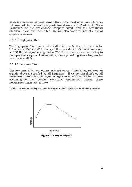
To illustrate the highpass and lowpass filters, look at the figures below:<br />
Figure 12: Input Signal<br />
23


