HXr Installation Manual, Rev A3 - Grand Rapids Technologies
HXr Installation Manual, Rev A3 - Grand Rapids Technologies
HXr Installation Manual, Rev A3 - Grand Rapids Technologies

Create successful ePaper yourself
Turn your PDF publications into a flip-book with our unique Google optimized e-Paper software.
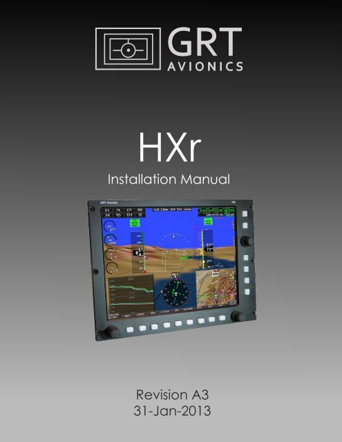
<strong>HXr</strong><br />
<strong>Installation</strong> <strong>Manual</strong><br />
<strong>Rev</strong>ision <strong>A3</strong><br />
31-Jan-2013
<strong>HXr</strong> <strong>Installation</strong> <strong>Manual</strong><br />
GRT Avionics<br />
Copyright© 2013<br />
3133 Madison Ave. SE • Wyoming, MI 49548<br />
(616) 245-7700 • www.grtavionics.com<br />
ii<br />
<strong>Rev</strong>ision A2
GRT Avionics<br />
<strong>HXr</strong> <strong>Installation</strong> <strong>Manual</strong><br />
FOREWORD<br />
Congratulations on your purchase of the GRT Avionics <strong>HXr</strong>! We are pleased that you have chosen<br />
our product to meet your flying needs.<br />
This manual describes installation of the GRT Hxr Electronic Flight Information System using the<br />
software version shown in the Record of <strong>Rev</strong>isions. Some differences may be observed when<br />
comparing the information in this manual to other software versions. Every effort has been made<br />
to ensure that the information in this manual is accurate and complete. Visit the GRT website,<br />
www.grtavionics.com, for the latest manual updates, software updates and supplemental<br />
information concerning the operation of this and other GRT products. GRT is not responsible for<br />
unintentional errors or omissions in the manual or their consequences.<br />
Information in the document is subject to change without notice. GRT Avionics reserves the right<br />
to change or improve their products and to make changes in the content of this material without<br />
obligation to notify any person or organization of such changes or improvements.<br />
Copyright © 2001 - 2012 GRT Avionics or its subsidiaries. All rights reserved.<br />
<strong>Rev</strong>ision A2<br />
iii
<strong>HXr</strong> <strong>Installation</strong> <strong>Manual</strong><br />
GRT Avionics<br />
RECORD OF REVISIONS<br />
<strong>Rev</strong>ision<br />
Date<br />
SW<br />
<strong>Rev</strong><br />
Change Description<br />
A 1-Dec-2012 1b Initial Release<br />
A1 19-Dec-2012 1b Added notes about audio output- Section 3.9 and Connector B<br />
Pinout Diagram<br />
Replaced <strong>HXr</strong> Interconnect Diagram with high-res image<br />
A2 09-Jan-2013 1d Updated wiring harness packages and part numbers in packing list–<br />
Section 1.5<br />
Updated & clarified wiring harness Connector Pinout Diagrams for<br />
Connector A, Connector B, and AHRS– Appendix<br />
<strong>A3</strong> 31-Jan-2013 1d Corrected pin assignment described in Section 3.7 from B1 to A18.<br />
Simplified trim/flap sensor wiring diagram, A14<br />
LIST OF EFFECTIVE SECTIONS<br />
Section Date <strong>Rev</strong>ision Notes<br />
Foreword 31-Jan-2013 A2<br />
1 09-Jan-2013 A2<br />
2 19-Dec02012 A<br />
3 31-Jan-2013 <strong>A3</strong><br />
4 19-Dec-2012 A<br />
5 19-Dec-2012 A<br />
Appendix 31-Jan-2013 <strong>A3</strong> <strong>HXr</strong> systems shipped after 1/08/13 include updated wiring<br />
harnesses as described in the Appendix of <strong>Rev</strong>ision A2.<br />
Installers of all units shipped prior to this date should refer to<br />
the Horizon Cable Description documents, available from<br />
www.grtavionics.com/documents, for Connector A, B and<br />
AHRS pinning instructions.<br />
iv<br />
<strong>Rev</strong>ision A2
GRT Avionics<br />
<strong>HXr</strong> <strong>Installation</strong> <strong>Manual</strong><br />
TABLE OF CONTENTS<br />
Section 1: General Description<br />
1.1 Introduction…………………………………………………………………………………………… 1-1<br />
1.2 Certification……………………………………………………………………………………………. 1-1<br />
1.3 System Description & Architecture………………………………………………………… 1-1<br />
1.4 Light Aircraft Avionics Primer………………………………………………………………….. 1-2<br />
1.5 <strong>HXr</strong> Accessories & Packing List………………………………………………………………. 1-5<br />
Section 2: Mechanical <strong>Installation</strong><br />
2.1 Display Unit <strong>Installation</strong>………………………………………………………………………….. 2-1<br />
2.2 AHRS <strong>Installation</strong>……………………………………………………………………………………… 2-1<br />
2.3 Magnetometer <strong>Installation</strong>……………………………………………………………………… 2-1<br />
2.4 Cooling Considerations………………………………………………………………………….. 2-3<br />
2.5 Pitot-Static Connections.....….………………………………………………………………….. 2-3<br />
Section 3: Wiring Considerations<br />
3.1 General Guidelines…………………………………………………………………………………. 3-1<br />
3.2 Power Connections…………………………………………………………………………………… 3-1<br />
3.3 Ground Connections……………………………………………………………………………… 3-2<br />
3.4 AHRS, Magnetometer & OAT Wiring……………………………………………………… 3-2<br />
3.5 Specific Equipment Interconnect Details…………………………………………………… 3-3<br />
3.6 Autopilot Source Switch…………………………………………………………………………. 3-3<br />
3.7 GPS Memory Power……………………………………………………………………………….. 3-3<br />
3.8 Inter-Display Communication………………………………………………………………….. 3-3<br />
3.9 Audio Tone Output………………………………………………………………………………….. 3-3<br />
<strong>Rev</strong>ision A2<br />
v
<strong>HXr</strong> <strong>Installation</strong> <strong>Manual</strong><br />
GRT Avionics<br />
Section 4: Checkout Procedures<br />
4.1 Display Unit Checkout …………………………………………………………………………… 4-1<br />
4.2 AHRS/Air Data Computer Test……………………………………………………….………. 4-1<br />
4.3 Magnetometer Location Validation….……………………………………………………. 4-1<br />
4.4 Check Uncorrected Magnetic Heading………………………………………………….. 4-3<br />
4.5 Magnetometer Calibration Procedure……………………………………………………. 4-3<br />
4.6 ARINC Checkout Procedure……………………………………………………………………. 4-6<br />
Section 5: Equipment Interconnect Details<br />
5.1 Serial Ports……………………………………………………………………………………………….. 5-1<br />
5.2 Inter-Display Link……………………………………………………………………………………. 5-1<br />
5.3 ARINC 429……………………………………..……………………………………………………….. 5-1<br />
5.4 Analog Input………………………………………………………………………………………….. 5-1<br />
5.5 USB Ports……………………………………………………………………………………………….. 5-2<br />
5.6 GRT GPS Modules………………………………………………………………………………….. 5-2<br />
Appendix: Mounting, Wiring, & Interface Diagrams<br />
vi<br />
<strong>Rev</strong>ision A2
GRT Avionics<br />
<strong>HXr</strong> <strong>Installation</strong> <strong>Manual</strong><br />
SECTION 1: GENERAL DESCRIPTION<br />
1.1 Introduction<br />
This document provides the physical, mechanical and electrical characteristics and installation<br />
requirements for the GRT <strong>HXr</strong> EFIS.<br />
This document, the <strong>HXr</strong> Set Up Guide and the <strong>HXr</strong> Users Guide make up the set of <strong>HXr</strong> user<br />
documentation. These documents, along with periodic software updates and other notices, are<br />
available at www.grtavionics.com under the Support menu.<br />
1.2 Certification<br />
The GRT <strong>HXr</strong> EFIS is not certified for installation in FAA Type Certificated Aircraft. It is designed<br />
and intended for installation in aircraft licensed as Experimental or Light-Sport.<br />
1.3 System Description & Architecture<br />
The GRT <strong>HXr</strong> EFIS (Electronic Flight Information System) consists of one or more panel mounted<br />
Display Units, one or more remotely mounted attitude-heading reference system (AHRS), and one<br />
or two remotely mounted magnetometers. The Display Unit is available with either a 10.4” or 12.1”<br />
screen. Dimensional drawings for both sizes, as well as the AHRS and magnetometer, are provided<br />
in the Appendix of this manual. The <strong>HXr</strong> is available as either a 12 or 28-volt system; the voltage<br />
is specified on the data tag of the display unit.<br />
Two AHRS packages are available. The Dual AHRS package (AHRS-2) is standard with the<br />
dual-display system, while the single AHRS (AHRS-1) is standard with a single display. The Dual<br />
AHRS is two identical AHRS units inside one module; this assures that both AHRS units are aligned<br />
with each other at all times. Dual AHRS is available with a single screen system as an option.<br />
The most basic configuration for <strong>HXr</strong> is a single EFIS screen to display the primary flight instruments<br />
of airspeed, altitude, heading, attitude, vertical speed, and rate of turn. To do this, the EFIS display<br />
unit works with a remotely-mounted attitude-heading reference system, or AHRS, and a<br />
magnetometer unit to determine aircraft attitude and heading information. The air data computer,<br />
located inside the AHRS box, is connected to the aircraft pitot/static system to determine airspeed<br />
and altitude. The GRT AHRS is unique in the industry in that it provides attitude data without gyros,<br />
GPS or pitot/static input to compute aircraft attitude, making it more reliable than systems that<br />
require external data.<br />
When GPS is added to the system, GPS track and a moving map are displayed on the map page<br />
of the primary display or the secondary display if equipped. GRT offers several different GPS<br />
modules for the <strong>HXr</strong>. A third-party GPS unit may also be used, such as a Garmin 430/530 or Garmin<br />
650/750. This feature is useful for adding IFR GPS approach capability to the <strong>HXr</strong> system. (IFR<br />
<strong>Rev</strong>ision A2 1-1
<strong>HXr</strong> <strong>Installation</strong> <strong>Manual</strong><br />
GRT Avionics<br />
approach sequencing is currently in development at GRT.) Note that the only GPS functions that<br />
import from a third-party GPS to the EFIS are track and position. Flight plan sequencing from such<br />
a GPS can be imported if the GPS is wired to the EFIS through the ARINC 429 port.<br />
When the <strong>Grand</strong> <strong>Rapids</strong> <strong>Technologies</strong> Engine Information System (EIS) unit is installed in the aircraft,<br />
every engine parameter imaginable is able to be monitored through the EFIS system. The EIS<br />
module senses the desired engine or environmental data, such as exhaust gas temperature, cylinder<br />
head temperature, oil temperature/pressure, and outside air temperature, and displays it on both<br />
the EIS screen and the EFIS screen. While the EIS displays it in numerical data only, the EFIS can<br />
display data in graphical format, which is useful and easy to read during flight. One notable feature<br />
is the EGT line graph, which tracks EGT data for each cylinder over time and allows easy and<br />
instantaneous rough-engine troubleshooting. The ENG page on the EFIS is dedicated to engine<br />
and environmental parameters. Engine data can also be displayed on a portion of the primary<br />
flight display page, fully customizable in-flight according to the pilot’s taste and situation.<br />
GRT strives to maintain open compatibility with third-party equipment vendors. This allows aircraft<br />
builders and pilots the freedom to choose whatever brands fit their mission and budget, as well<br />
as the flexibility for easy upgrades as technology evolves. Radios, transponders, ADS-B modules,<br />
and many other third-party units interface with the GRT <strong>HXr</strong> through RS-232 serial, ARINC 429,<br />
RS-422, and USB ports. VOR/localizer data, traffic alerts, and in-flight weather are very common<br />
additions that are easily displayed on the EFIS screen. The <strong>HXr</strong> features the capability to mount<br />
the radio, transponder and engine monitor in a remote location to simplify the design of the<br />
instrument panel. The addition of a second or third display unit doubles or triples the number of<br />
available serial and USB ports available, allowing use of more third-party devices. The Ethernet<br />
inter-display link between EFIS screens allows data from most devices to be shared among screens<br />
for redundancy and convenience.<br />
See Section 5, the Appendix of this manual, and the Support section of grtavionics.com for<br />
information on various GRT system & third party equipment configurations.<br />
1.4 Light Aircraft Avionics Primer<br />
Modern flight instrumentation systems may seem intimidating, but they can be simpler to install<br />
than their analog counterparts. This section provides some basic information for aircraft builders<br />
new to the world of electronic flight display systems.<br />
D-Sub Connectors<br />
A key element to designing a glass-panel installation is the communication between different<br />
components of the system. The internal circuits of each unit are wired to use D-sub connectors for<br />
easy external wiring of required and optional components. The main connectors of the Horizon<br />
system are two 25-pin D-Subs, referred to in this manual as Connectors A and B. Each pin of the<br />
connector is wired to an internal component of the display unit circuitry. Some pins are hard wired<br />
1-2 <strong>Rev</strong>ision A2
GRT Avionics<br />
<strong>HXr</strong> <strong>Installation</strong> <strong>Manual</strong><br />
to required elements, such as the AHRS input. Others are designated as serial ports or other<br />
communication ports described below.<br />
Analog Input<br />
Some pins on the GRT EFIS connectors are designated as Analog input. These inputs use variations<br />
in voltage levels to perform simple tasks. The most common use for analog data in GRT EFIS systems<br />
today is for position indicators such as trim, flaps, and squat switches. VOR/Localizer data can be<br />
in analog format, but has overwhelmingly been replaced by serial data or ARINC 429 for simplicity<br />
and better performance.<br />
Grey Code<br />
Grey code is an analog language used by most transponders, especially older ones, to decipher<br />
altitude encoder information. A range of pins on older GRT EFIS systems is designated as Grey<br />
code input. Newer transponders can use serial data instead of Grey code, which vastly simplifies<br />
the wiring process. Because Grey code is rapidly becoming phased out in favor of serial data, the<br />
<strong>HXr</strong> does not support it.<br />
Serial Ports<br />
Serial ports are user defined, meaning that the aircraft builder can choose which devices use each<br />
port. Each serial port consists of two pins– a Transmit (OUT or Tx) and a Receive (IN or Rx)–that<br />
exchange information between the display unit and a connected device such as a GPS, radio or<br />
autopilot. Devices that receive and transmit information use one “whole” serial port. Some<br />
components only require an IN or OUT. For example, the EIS connects to an IN port because it<br />
sends information to the EFIS, but the EFIS does not respond back. The other half of the port, the<br />
OUT, may be used for a device that only requires data FROM the EFIS, such as a transponder that<br />
uses encoder data from the EFIS. During the display unit Setup Procedure, you will use the system<br />
Setup Guide or Equipment Supplement to program the display unit and “tell” it which device uses<br />
each serial port and which baud rate it requires.<br />
Data is transported through the serial ports to make the devices work. A stream of serial data is<br />
like a sentence, and data packets are like the words. Data packets are transmitted in a<br />
predetermined order and frequency. This frequency is known as the baud rate. A device that<br />
communicates at a baud rate of 9600 delivers 9600 coded data packets per second in a sequence<br />
that the receiving device expects. The baud rate of the serial port in the EFIS must be configured<br />
to match that of the device; otherwise, the “sentences” of data packets will be scrambled. Note<br />
that only one baud rate may be programmed per serial port, so if two devices share a port, they<br />
must use the same baud rate.<br />
ARINC 429<br />
ARINC 429 is a data transfer method designed specifically for use in aircraft avionics systems. It<br />
was originally intended for use in airliners and other commercial aircraft where large amounts of<br />
data are transferred. It can be more confusing for a beginner to wire than a serial port because it’s<br />
like a four-lane highway; each data stream IN and OUT requires two wires, referred to as A and B.<br />
<strong>Rev</strong>ision A2 1-3
<strong>HXr</strong> <strong>Installation</strong> <strong>Manual</strong><br />
GRT Avionics<br />
ARINC 429 data rates are either 12.5 or 100 kilobits per second; therefore, each ARINC port is set<br />
to either LOW (12 kbps) or HIGH (100 kbps) depending on the requirements of the device it runs.<br />
An ARINC device commonly used with GRT systems is the Garmin GNS430/530 IFR-certified GPS,<br />
which uses the ARINC connection for better performance over the old analog VOR/Localizer data..<br />
USB<br />
The preferred method of data transmission for newer devices is USB. Just like the USB port on your<br />
computer, an EFIS USB port is easy to connect and transmits large amounts of data quickly. USB<br />
devices do not require you to program a baud rate. The <strong>HXr</strong> has two USB ports that may be used<br />
for two USB devices, or you may attach a USB hub to run up to three devices. Some ADS-B units,<br />
such as the Radenna Skyradar, offer USB data transmission. Software updates are also delivered<br />
to the EFIS via USB– simply install the software update files onto a USB thumb drive from the GRT<br />
website, then install the thumb drive to the EFIS USB port. The EFIS will upload the files when you<br />
follow the Update instructions in the system Setup Guide. Most people choose to leave a USB<br />
extension cable plugged into the USB port for easy software updating. Flight and engine data may<br />
be recorded to a USB thumb drive as a “demo file” for later examination– a useful feature for<br />
collecting flight test data.<br />
Bluetooth<br />
The <strong>HXr</strong> features a new method of EFIS data communication: Bluetooth wireless. With this feature,<br />
the EFIS can communicate with an Android-based tablet or smartphone that has the GRT App. This<br />
is particularly useful in tandem aircraft, where the back seat passenger can have their own PFD on<br />
a kneeboard. They can even change radio frequencies and adjust flight plans without getting near<br />
the EFIS or the rest of the instrument panel. (Note: The Android app is still in development at GRT;<br />
the beta version will be available for free download by the end of 2012.) The Bluetooth transmitter<br />
dongle is a tiny device about the size of a thumbnail that plugs into one of the USB ports in the<br />
back of the display unit.<br />
Physical Wiring<br />
All the wires supplied with the EFIS system are 22-gauge. Many wires are included in the wiring<br />
harness for the EFIS, and some are pre-pinned. GRT pre-connects wires that are guaranteed to be<br />
used by the builder. The wires are different colors so they may be traced throughout the airframe<br />
and avionics compartment. Labeling the ends of the wires is a good practice, especially in complex<br />
installations where there may be dozens of wires.<br />
It will take some effort to figure out exactly how long each wire must be to reach remotely-mounted<br />
devices, but too long is always preferable to a wire that barely reaches. Always allow several inches<br />
of extra “service loop” in your wiring installations to allow easy removal of connected components<br />
from the mount locations and prevent wires from vibrating loose under tension.<br />
Most wires already have connector ends on them, but some do not because each airplane requires<br />
different lengths of wire for different applications. Each EFIS comes with pin connectors that will<br />
1-4 <strong>Rev</strong>ision A2
GRT Avionics<br />
<strong>HXr</strong> <strong>Installation</strong> <strong>Manual</strong><br />
need to be crimped to the ends of wires after they are trimmed to length. For information on how<br />
to crimp wires, there are some good videos on EAA’s Hints for Homebuilders website, as well as<br />
written information in the publications listed at the end of this section.<br />
The pinout diagrams included in this manual are designed to give you the pre-wired pin locations<br />
for required components, as well as the pin locations of the serial ports and optional items. NC<br />
means “no connection,” or a pin that leads to nothing inside the EFIS. TX, or transmit, designates<br />
a Serial OUT, and RX, or receive, designates a Serial IN connection.<br />
The graphic interface diagrams are provided as an example of how different devices can be wired<br />
to the EFIS display units. These diagrams offer an efficient way to use the serial ports based on<br />
many years of experience of our techs. Of course, this is just an example, and different third-party<br />
equipment and serial port configurations are left up to the builder and panel designer.<br />
For More Information…<br />
Depending on what your “mission” is, you may want a simple VFR system, or an IFR system with<br />
many built-in redundancies. The GRT system enables customization for the whole range of<br />
possibilities, from simple to sophisticated, depending on the builder’s desire and skill level.<br />
While this manual covers the very basics of EFIS wiring & communication and the GRT <strong>HXr</strong>-specific<br />
details, there are many very important safety aspects of aircraft wiring that we cannot even begin<br />
to discuss in this manual. The techs at GRT recommend the following sources for more information<br />
on proper aircraft avionics & electrical system design:<br />
by Bob Nuckolls is a great place to start. This manual covers everything<br />
from the very basics of electricity to the proper design and installation of sophisticated IFR-capable<br />
systems.<br />
Longtime EAA columnist Tony Bingelis’s books, the series, have long been a<br />
staple of experimental aircraft builder knowledge. In addition to wiring considerations, Mr. Bingelis<br />
discusses all aspects of kitplane building, from spinner to tail.<br />
FAA Advisory Circular 43.13-2B provides the “certified” reference for safe and durable aircraft wiring<br />
techniques, though it is a bit outdated. It is available online for free download from www.faa.gov.<br />
All of the above publications are available at Amazon.com.<br />
The Experimental Aircraft Association has compiled a collection of videos called Hints for<br />
Homebuilders on its website, www.eaa.org. A quick search through these will give you valuable<br />
hints on various wiring topics, including properly crimping D-sub/Molex connector pins.<br />
<strong>Rev</strong>ision A2 1-5
<strong>HXr</strong> <strong>Installation</strong> <strong>Manual</strong><br />
GRT Avionics<br />
1.5 <strong>HXr</strong> Accessories and Packing List<br />
Your <strong>HXr</strong> system has been carefully inspected and packaged. It includes the EFIS display unit and<br />
associated accessories. Before installing and getting started with your new system, please use the<br />
packing list that accompanied the EFIS and the following paragraphs to ensure that no items are<br />
missing and that there is no visible damage. If any parts are missing or damaged, please contact<br />
GRT Avionics or your GRT dealer immediately.<br />
There are a number of options for remotely mounted radios, transponders, ADS-B and XM Weather<br />
receivers that work with <strong>HXr</strong>. Because this list is constantly growing, please refer to the GRT website,<br />
www.grtavioncs.com, for the most current details about Compatible Equipment options. Some of<br />
them are available for purchase from GRT as part of your EFIS package.<br />
Three- or four-display packages contain the same accessories as a Dual Display package and may<br />
be equipped with similar options. The EFIS to EFIS wiring harness supplied will accommodate the<br />
number of display units supplied.<br />
Single Display Package<br />
Qty Part Number Description<br />
1 MFD-<strong>HXr</strong>-10.4 Multi-Function Display, <strong>HXr</strong> EFIS (optional 12.1)<br />
1 AHRS-1 Attitude-Heading Reference System w/Magnetometer (single)<br />
1 OAT-03 Outside Air Temperature Probe<br />
1 CAB-HX-KIT-01 Display Unit Wiring Harness Kit<br />
1 CAB-AHRS-01 AHRS Wiring Harness<br />
1 USB Memory Stick<br />
Dual Display Package<br />
Qty Part Number Description<br />
2 MFD-<strong>HXr</strong>-10.4 Multi-Function Display, <strong>HXr</strong> EFIS (optional 12.1)<br />
1 AHRS-2 Attitude-Heading Reference System w/Magnetometers (dual)<br />
1 OAT-03 Outside Air Temperature Probe<br />
2 CAB-HX-KIT-01 Display Unit Wiring Harness Kit<br />
2 CAB-AHRS-01 AHRS Wiring Harness<br />
1 Inter-Display Ethernet Cable<br />
2 USB Memory Stick<br />
1-6 <strong>Rev</strong>ision A2
<strong>HXr</strong> <strong>Installation</strong> <strong>Manual</strong><br />
GRT Avionics<br />
<strong>HXr</strong> EFIS Options<br />
Qty Part Number Description<br />
GPS-H/E GRT External GPS Module<br />
GPS-RAIM-H/E RAIM GPS Module<br />
GPS-LPV TSO-C145c IFR GPS<br />
(Varies)<br />
Engine Monitor Package (EIS)<br />
XM-WEATHER XM Weather Receiver<br />
USB-EXT USB Extension Cable<br />
1-7 <strong>Rev</strong>ision A2
GRT Avionics<br />
<strong>HXr</strong> <strong>Installation</strong> <strong>Manual</strong><br />
SECTION 2: MECHANICAL INSTALLATION<br />
2.1 Display Unit <strong>Installation</strong> Considerations<br />
Mount the display unit(s) in the desired location in the instrument panel. The main consideration<br />
in choosing a location is the ability to view the display unit and reach its controls. Since the display<br />
is fully sunlight-readable, no consideration for shielding the display unit from sunlight is required.<br />
Be mindful of the space behind the instrument panel as well; some aircraft with tip-up canopies,<br />
for example, have canopy supports that may interfere with the back of the EFIS when the canopy<br />
is closed. See the Appendix of this manual for <strong>HXr</strong> component mounting templates.<br />
The use of nut plates behind the instrument panel greatly simplifies the task of installing and<br />
removing the 6 screws used to retain the display unit in the panel. #6 socket cap stainless steel<br />
screws are recommended.<br />
These two FAA Advisory Circulars provide suggestions for positioning display units with respect to<br />
visual field and control location: While they are intended for Part 23 (Certified) Airplanes, the<br />
information is useful and applicable to experimental airplanes also:<br />
• AC23.1311-1B <strong>Installation</strong> of Electronic Displays in Part 23 Airplanes<br />
• AC 20-138A Airworthiness Approval of Global Navigation Satellite System Equipment<br />
2.2 AHRS <strong>Installation</strong><br />
The AHRS is not affected by wiring, magnetic field, heat, temperature or vibration influences.<br />
However, good practices suggest that it should be located where these influences are minimized.<br />
The pitot and static connections are made to the AHRS, so its location should consider this.<br />
It is important that the AHRS is mounted so that the roll, pitch and yaw axes of the AHRS are parallel<br />
to the roll, pitch and yaw axes of the aircraft. The precision that this is achieved influences the final<br />
performance of the EFIS.<br />
There is no requirement that the AHRS roll, pitch or yaw axes be parallel to those of its associated<br />
display unit.<br />
Be sure to mount the AHRS with the connector toward the rear of the airplane. Observe the label<br />
on the AHRS to ensure it is oriented correctly.<br />
2.3 Magnetometer <strong>Installation</strong><br />
Determining the location of the magnetometer requires considerable care because of the<br />
magnetometer's sensitivity to magnetic disturbances generated by the airplane. No periodic<br />
maintenance is required for the magnetometer, although it is desirable to mount it in a location<br />
<strong>Rev</strong>ision A 2-1
<strong>HXr</strong> <strong>Installation</strong> <strong>Manual</strong><br />
GRT Avionics<br />
that allows access to it if necessary. The most important consideration when mounting the<br />
magnetometer is choosing a location in the airplane that is away from magnetic disturbances. It<br />
is quite amazing how sensitive the magnetometer is to these disturbances, and how much error<br />
this can cause in the magnetic heading reported by the AHRS.<br />
Keep the magnetometer at least 12 inches away from any current carrying wires (such as navigation<br />
or landing light wires), and more than 18 inches from ferrous metal, such as the steel mass balance<br />
tube that is typically used in the leading edge of ailerons. Use non ferrous hardware for mounting<br />
the magnetometer. Keep the magnetometer as far as possible from transmitting antennas<br />
(transponder and especially comm. radio) and their coaxial cables.<br />
You can test your proposed magnetometer location prior to mounting the magnetometer itself by<br />
placing an ordinary compass at the spot. Then:<br />
1. Turn on and off any electrical equipment whose wiring passes within 2 feet of the magnetometer.<br />
2. Move the flight controls from limit to limit.<br />
3. If the magnetometer is located within 2 feet of retractable landing gear, operate the landing<br />
gear.<br />
4. Operate the comm. radio (transmit) and transponder (IDENT).<br />
Observe the compass while doing each of the above. The goal is no movement, or compass<br />
movement of less than 5 degrees. If you observe greater movement, try another location. After<br />
the installation and wiring of the magnetometer and display unit(s) is complete, a more sensitive<br />
check for magnetic disturbances will be conducted.<br />
Each magnetometer and its associated AHRS work together. For this reason, they must be oriented<br />
in the same directions, that is, the pitch, roll and yaw axes of the magnetometer and the AHRS<br />
need to be parallel. A standard level can be used to orient the magnetometer and AHRS such that<br />
they are equal in roll, and in pitch. For yaw, the orientation of these devices should be parallel to<br />
the fuselage centerline. In cases where the magnetometer is mounted in the wing, it may be possible<br />
to orient the magnetometer parallel to a wing rib, if these ribs are oriented in the wing such that<br />
they are parallel to the fuselage centerline. This is quite practical in airplanes such as Van’s RV’s.<br />
Figure 2-1 shows this.<br />
There is no requirement that the Magnetometer roll, pitch or yaw axes be parallel to those of its<br />
associated display unit.<br />
Be sure to mount the magnetometer with the connector toward the rear of the airplane. Observe<br />
the label on the magnetometer to ensure it is oriented correctly.<br />
2-2 <strong>Rev</strong>ision A
GRT Avionics<br />
<strong>HXr</strong> <strong>Installation</strong> <strong>Manual</strong><br />
Figure 2-1: Magentometer/AHRS alignment<br />
2.4 Cooling Considerations<br />
The GRT Horizon <strong>HXr</strong> EFIS does not require external cooling. However, as with all electronic<br />
equipment, lower operating temperatures extend equipment life. Units in an avionics stack heat<br />
each other through radiation, convection and sometimes by direct conduction. Even a standalone<br />
unit operates at a higher temperature in still air than in moving air. The Horizon <strong>HXr</strong> contains<br />
an internal cooling fan. Be sure that there is adequate air available so that it can cool the display<br />
unit. A few openings in the glare shield are usually more than adequate to allow natural air flow.<br />
If external forced air is used, be certain that the cooling air does not contain water – a problem<br />
often encountered when using external air.<br />
2.5 Pitot/Static Connections<br />
The AHRS contains the Air Data Computer. The ADC requires connection to the aircraft pitot static<br />
system. Connections on the AHRS unit take a 1/8 – 27 NPT male fitting. Connections and the entire<br />
pitot static system must be leak tight. Refer to AC 43.13.1B for approved methods to achieve this.<br />
<strong>Rev</strong>ision A 2-3
<strong>HXr</strong> <strong>Installation</strong> <strong>Manual</strong><br />
GRT Avionics<br />
THIS PAGE INTENTIONALLY BLANK<br />
2-4 <strong>Rev</strong>ision A
GRT Avionics<br />
<strong>HXr</strong> <strong>Installation</strong> <strong>Manual</strong><br />
SECTION 3: WIRING CONSIDERATIONS<br />
3.1 General Guidelines<br />
Wires that are certain to be used are pre-installed in the EFIS cable assembly connectors. Optional<br />
connections to the EFIS are not installed in the D-sub connectors at the factory, however, colored<br />
aviation-grade wires with pre-installed D-sub connector contacts are included for these connections.<br />
The cable description diagram includes recommended wire colors for each connection to the EFIS<br />
components.<br />
When routing the wiring, the following guidelines should be considered:<br />
• Good practices for physical installation of the wiring should be followed, such as grommets where<br />
wires pass through sheet metal, considering for chaffing and interference with moving<br />
mechanisms, etc.<br />
• Cable lengths should include enough extra length to allow for servicing the equipment. For<br />
example, the cables which plug into the display unit should be long enough to allow them to be<br />
connected to display unit with the display unit not installed in the instrument panel.<br />
• In general, routing of the wiring is not critical, as the EFIS is designed to be tolerant of the electrical<br />
noise and other emissions typically found in aircraft. Some consideration should be given to avoid<br />
routing wires near antennas, or other locations that could impart high levels of electromagnetic<br />
signals on the wiring.<br />
• The checkout procedures outlined in Section must be completed to verify the EFIS is not affected<br />
by radio transmissions on any frequency.<br />
• Consider the effects of individual component failures in the design of the system as a whole to<br />
create redundancy where necessary.<br />
3.2 Power Connections<br />
The display units each include 3 isolated power input connections. This allows redundant power<br />
sources, such as a main and secondary bus. The display units consume approximately 1 amp,<br />
making even a small 3 Amp-Hour gel cell a suitable emergency source.<br />
The configuration of the power supplied to the display unit(s) is left to the installer. Considerations<br />
such as the number of power buses, the desire or not to supply one piece of equipment with power<br />
from redundant buses (which in theory allows the possibility of one device affecting both buses),<br />
the configuration of the electrical system with respect to backup equipment, and so on, may dictate<br />
the best configuration for a particular airplane.<br />
<strong>Rev</strong>ision A1 3-1
<strong>HXr</strong> <strong>Installation</strong> <strong>Manual</strong><br />
GRT Avionics<br />
No provision is included within the display units for a power switch. If a power switch is desired<br />
for the EFIS, the +12V power should be controlled with the switch (not ground). It is desirable to<br />
have the display units and AHRS off during the engine start if all of the buses which power them<br />
are used for supplying power to the engine starter. This maximizes the current available for the<br />
starter, and may extend the life of the CCFL backlight in the display unit.<br />
The display units include internal thermally-activated fuses. This protects the equipment from<br />
internal electrical faults. Power supplied to the EFIS must pass through an external fuse or circuit<br />
breaker. It should be sized to allow at least 2 amps per display unit, with a maximum rating of 5<br />
amps.<br />
The AHRS and display units monitor all of their power inputs, and alarms are available to annunciate<br />
the loss of any power source that was provided and is expected to be working according to the<br />
“General Setup” menu.<br />
3.3 Ground Connections<br />
The cable assembly provided includes 22 gauge wire for the ground return of the display units.<br />
This will result in a voltage drop of about 0.015 V/foot, which is acceptable for wire lengths up to<br />
10 feet.<br />
3.4 AHRS, Magnetometer & OAT Wiring<br />
The AHRS & magnetometer cable supplied with the EFIS does not have a D-sub connector installed<br />
on the display unit or magnetometer cable end. This makes it easier to route this cable through<br />
the airplane. After the cable has been routed, the wires can be cut to length if desired, although<br />
new D-sub pins would need to be installed. If the wires are not cut, inspect the D-sub connector<br />
pins to verify they have not been damaged. Insert the indicated wire color into the appropriate<br />
D-sub connector housing hole according to the appropriate pinout diagram, located in the<br />
Appendix of this manual. If desired, the crimp-type D-sub connector can be replaced with a<br />
solder-type connector.<br />
All magnetometer connections are made directly to the mating AHRS. This wiring includes the<br />
power connections necessary for the magnetometer to operate. Each AHRS and magnetometer<br />
pair is calibrated together for optimal accuracy, and thus this paring should be maintained.<br />
An OAT sensor may be connected to the AHRS package to provide OAT for true airspeed<br />
calculations. More commonly, the OAT is connected to EIS.<br />
3-2 <strong>Rev</strong>ision A1
GRT Avionics<br />
<strong>HXr</strong> <strong>Installation</strong> <strong>Manual</strong><br />
3.5 Specific Equipment Interconnect Details<br />
Detailed wiring information and setup instructions for specific GRT and third-party avionics<br />
equipment are provided in Equipment Supplements. These supplements can be downloaded from<br />
the GRT website in the Support section.<br />
Examples of wiring diagrams and EFIS pinout diagrams can be found in the Appendix of this manual.<br />
3.6 Autopilot Source Switch<br />
Depending on the other equipment installed in the airplane, switches may be necessary or desirable<br />
for some functions. A switch to allow the autopilot to be controlled by the EFIS, or directly from<br />
the GPS, allows the GPS to control the autopilot in the event the display unit which normally<br />
commands the autopilot is not functioning.<br />
3.7 GPS Memory Power<br />
Internal GPS memory may be maintained when the aircraft is parked on the ground by connecting<br />
Pin A18 on the EFIS to the aircraft battery. The draw is less than one milliamp, but it may draw the<br />
aircraft’s battery power down over periods of inactivity. When Pin A18 is not wired to the battery,<br />
the GPS may take 2-3 minutes longer to find its position after startup. Pilots who do not fly at least<br />
once per week should leave the GPS memory power wire disconnected.<br />
3.8 Inter-Display Communication<br />
Display units communicate between themselves via Ethernet cable so that most entries made<br />
during flight can be made from any display unit, and will be applied to all. The ethernet connection<br />
is fast enough to transport large amounts of data, such as weather information, from one screen<br />
to the other.<br />
3.9 Audio Tone Output<br />
Future growth is planned to allow audio output to provide a warning tone, or possibly other type<br />
of audio output. This output may be connected to a spare input on the aircraft’s intercom system.<br />
Volume level will be controlled by menu settings within the display unit. (NOTE: This option is not<br />
yet available, but Pin B24 has been reserved for it.)<br />
<strong>Rev</strong>ision A1 3-3
<strong>HXr</strong> <strong>Installation</strong> <strong>Manual</strong><br />
GRT Avionics<br />
THIS PAGE INTENTIONALLY BLANK<br />
3-4 <strong>Rev</strong>ision A1
<strong>HXr</strong> <strong>Installation</strong> <strong>Manual</strong><br />
GRT Avionics<br />
SECTION 4: CHECK OUT & CALIBRATION<br />
4.1 Display Unit Check Out<br />
1. Apply power to the display unit. The LCD may flicker, and within 10 seconds, the display should<br />
show the first page.<br />
2. If multiple power buses connect to the display unit, apply power from each bus individually<br />
to test.<br />
4.2 AHRS/Air Data Computer Test<br />
1. Verify that the serial ports to all AHRS units have been programmed into the EFIS. (Refer to<br />
the <strong>HXr</strong> Setup Guide for instructions to program serial ports.)<br />
2. Apply power to display unit with internal AHRS.<br />
3. Proper operation of the AHRS and magnetometer is indicated as follows:<br />
a. The display unit shows altitude and airspeed tapes.<br />
b. Attitude and heading data appears on the screen at the completion of the alignment period<br />
(typically less than 2 minutes).<br />
c. No "ATTITUDE FAIL" message is shown on the PFD screen.<br />
d. No failure messages are listed on the EFIS screen (check lower left corner for MSG box).<br />
4. Press “MORE” softkey, then “SET MENU.” Select the “AHRS Maintenance” page.<br />
5. Verify AHRS communications status is valid, and AHRS status is OK. Verify the AHRS is receiving<br />
serial communications from the display unit by observing that no data fields are grayed out.<br />
4.3 Magnetometer Location Validation<br />
1. Park the aircraft on a level surface and start the engine.<br />
2. Press the MORE soft key on the EFIS display, then press the SET MENU soft key. Scroll to and<br />
select AHRS Maintenance. Locate Magnetic Heading field on this screen.<br />
NOTE: Do not use the heading data shown on the heading tape on the PFD for calibration<br />
because this is a composite reading of several other pieces of information. The Magnetic<br />
Heading field contains instantaneous data on magnetic heading only.<br />
4-1 <strong>Rev</strong>ision A
<strong>HXr</strong> <strong>Installation</strong> <strong>Manual</strong><br />
GRT Avionics<br />
3. Observe the Magnetic Heading and verify it does not change by more than +/- 2 degrees<br />
while doing the following:<br />
a. Turn on and off any electrical equipment whose wiring passes within 2 feet of the<br />
magnetometer.<br />
b. Move all flight controls from limit to limit.<br />
c. Shut down the engine and observe the heading while the engine is not running, noting<br />
any difference.<br />
d. For aircraft with retractable landing gear: If the magnetometer is located within 2 feet of<br />
retractable landing gear, support the aircraft using proper jacking equipment, then repeat<br />
Step 1 while operating the landing gear.<br />
e. If greater than +/- 2 degree change is noted, either relocate the magnetometer or the<br />
offending wiring or metallic materials. Recheck.<br />
The most common cause is simply magnetic disturbances near the magnetometer. This can be<br />
caused by ferrous metal (any metal that a magnet will stick to), control cables, or cable carrying<br />
electrical currents, such as navigation or landing lights, being too close to the magnetometer. If<br />
there is any doubt about a location, try moving the magnetometer to another location. Use tape<br />
or other temporary means to hold it in place, roughly aligned with the orientation of the AHRS,<br />
and repeat the test.<br />
Wiring Problems<br />
1. Some wiring problems will be detected by the AHRS built-in-test functions. The will result in<br />
an AHRS Attitude Fail Message, and an "AHRS: Magnetometer X, Y or Z-Axis Failed" message<br />
on the status page that is accessed by the STATUS button from any page. If this message is<br />
present, the wiring to the magnetometer should be checked.<br />
2. It is also possible that no built-in-test failure is reported, but the wiring is still incorrect. This<br />
can occur if the magnetometer X, Y, Z inputs are swapped. To check for this, point the airplane<br />
at various directions listed in the table below, with the magnetometer in an approximately<br />
level position (it may need to be removed from the airplane and held by hand). Use the AHRS<br />
Maintenance page to observe the "Magnetometer X, Y, Z Raw Data". The following should be<br />
observed:<br />
4-2 <strong>Rev</strong>ision A
<strong>HXr</strong> <strong>Installation</strong> <strong>Manual</strong><br />
GRT Avionics<br />
Magnetic<br />
Direction<br />
North<br />
East<br />
X Raw Data* Y Raw Data* Z Raw Data*<br />
Positive Value<br />
above 1000<br />
Between -500 and<br />
+500<br />
South Less than -1000<br />
West<br />
Between -500 and<br />
+500<br />
Between -500 and<br />
+500<br />
Greater than<br />
+1000<br />
Between -500 and<br />
+500<br />
Less than -1000<br />
Greater than<br />
+1500**<br />
Greater than<br />
+1500**<br />
Greater than<br />
+1500**<br />
Greater than<br />
+1500**<br />
* The raw data readings will appear to shift left and right on the screen once per second, as the<br />
signs change for a brief moment. This is normal, and the brief sign changes should be ignored<br />
when using this table of the expected readings.<br />
** The Z Raw data will be greatly influenced by where on the earth the test is performed. Positive<br />
values will be observed in the northern hemisphere and negative values in the southern hemisphere.<br />
4.4 Check Uncorrected Magnetic Heading<br />
While the calibration procedure can remove errors as large as 127 degrees, accuracy is improved<br />
if the location chosen for the magnetometer requires corrections of less than 30 degrees.<br />
To check the accuracy of the uncorrected magnetic heading:<br />
1. Scroll to Magnetometer Calibration on the AHRS Maintenance page and select it.<br />
2. While on this page, rotate the airplane 360 degrees. A red graph will appear on this page<br />
showing the calculated errors.<br />
If errors of greater than 30 degrees are observed, see section 4.3 to troubleshoot.<br />
4.5 Magnetometer Calibration Procedure<br />
The magnetometer must be calibrated before the first flight of the aircraft. Magnetometer<br />
calibration is required to achieve accurate magnetic heading readings. This calibration corrects for<br />
errors induced by magnetic disturbances local to the sensor, such as ferrous metal objects.<br />
NOTE: The AHRS will not allow magnetometer calibration to be initiated if the airspeed is greater<br />
than 50 mph to prevent inadvertent selection while in flight. If calibration is successful, the existing<br />
calibration data (if any) will be replaced with the new corrections.<br />
The Magnetometer Calibration page will help guide you through this procedure with its on-screen<br />
menus and prompts.<br />
4-3 <strong>Rev</strong>ision A
<strong>HXr</strong> <strong>Installation</strong> <strong>Manual</strong><br />
GRT Avionics<br />
1. Point the aircraft to magnetic north, in an area without magnetic disturbances, such as a<br />
compass rose.<br />
A simple means of pointing the airplane toward magnetic north is to taxi the airplane slowly<br />
and use the GPS ground track to determine when you are taxiing in a magnetic north direction.<br />
Make small corrections to the direction of travel of the airplane, and continue to taxi for several<br />
seconds for the GPS to accurately determine your ground track. The GPS cannot determine<br />
your track unless you are moving.<br />
2. After the aircraft is positioned accurately, turn ON the EFIS. (If it was already on, then turn it<br />
OFF, and then back ON again.)<br />
3. Allow at least 1 minute for the AHRS to fully stabilize.<br />
4. Press the MORE soft key, then the SET MENU soft key. Scroll to and select AHRS Maintenance.<br />
Scroll to and select Magnetometer Calibration field on this screen.<br />
5. Press Start soft key.<br />
6. The first question is “Are you sure?” Press YES if you are sure.<br />
7. Verify the airplane is still pointed to magnetic north. Answer the question “Are the aircraft,<br />
AHRS, and magnetometer pointing to magnetic north?” with YES. A message will appear at<br />
the bottom of the screen indicating the system is waiting for the gyros to stabilize.<br />
8. As soon as the message “Calibration in Progress” is displayed (within 15 seconds), rotate the<br />
aircraft 360 degrees plus 20 degrees in a counter-clockwise manner (initially towards west).<br />
The airplane does not need to be rotated in place, but simply pulled or taxied in a circle. The<br />
airplane must be rotated completely through 360 degrees, plus an additional 20 degrees past<br />
magnetic north, within 3 minutes after initiating the calibration. The airplane should be rotated<br />
slowly, such that it takes approximately 60 seconds for the complete rotation.<br />
9. If calibration is successful, the AHRS will re-start itself automatically, and begin using the<br />
corrections. While re-starting, the AHRS will not provide data. This will result in the AHRS data<br />
disappearing from the display unit for about 10 seconds.<br />
10. If calibration is unsuccessful, one of two things will happen. In either case, the calibration<br />
procedure must be repeated.<br />
a. If the airplane is rotated too rapidly, the calibration will not end after the airplane has been<br />
rotated 380 degrees.<br />
b. It will exit calibration mode, and will show “Calibration INVALID - Maximum correction<br />
exceeded” if a correction of greater than 127 degrees is required. (Invalid - OVERLIMIT will<br />
be displayed on the AHRS maintenance page next to the Magnetometer Calibration field.)<br />
4-4 <strong>Rev</strong>ision A
<strong>HXr</strong> <strong>Installation</strong> <strong>Manual</strong><br />
GRT Avionics<br />
A correction of greater than 127 degrees can be caused by incorrect mounting of the<br />
magnetometer, or location of the magnetometer too close to ferrous metal in the aircraft,<br />
or starting with the airplane not pointed toward magnetic north or magnetometer wiring<br />
errors.<br />
The accuracy of the magnetometer calibration can now be verified.<br />
11. Point the airplane toward magnetic north.<br />
12. Turn ON the AHRS (if already ON, turn it OFF, and then back ON).<br />
13. Verify the AHRS (on AHRS Maintenance page) shows a heading close to north. (Small errors<br />
are likely to be a result of not positioning the airplane to the exact heading used during<br />
magnetometer calibration.)<br />
14. Select the Magnetometer Calibration page. (Do not activate the calibration this time.)<br />
15. Rotate the airplane through 360 degrees, and inspect the Calculated Error graph (the red line)<br />
drawn on the screen.<br />
The magnetic heading errors should be less than 5 degrees, and can typically be reduced to about<br />
2 degrees. Accurate magnetic heading is required for the AHRS to display accurate heading data,<br />
and to allow accurate wind speed/direction calculations.<br />
The graph will also show the correction stored in the AHRS as a green line. The green line will be<br />
within the +/- 30 degree range if the magnetometer was mounted in a good location, and was<br />
mounted accurately with respect to the AHRS.<br />
The status of the magnetometer correction data is indicated by the field next to the Magnetometer<br />
Calibration setting on the AHRS Maintenance page. If the field has the message “Change to open<br />
page,” then no valid data is stored within the AHRS and it must be recalibrated. If the field says<br />
“Valid,” it means that the data is present. Keep in mind that the accuracy of this data is not assured<br />
because it is dependent on how carefully the user performed these steps. The calibration data<br />
should be cross-checked with reliable ground references such as a compass rose or runway<br />
headings before flight.<br />
Congratulations! Magnetometer calibration is now complete.<br />
4-5 <strong>Rev</strong>ision A
<strong>HXr</strong> <strong>Installation</strong> <strong>Manual</strong><br />
GRT Avionics<br />
4.6 ARINC Checkout Procedure<br />
If the ARINC 429 input and/or outputs are wired, these interfaces must be verified.<br />
ARINC 429 Inputs<br />
Press the MORE soft key, then the SET MENU soft key and go to the "Display Unit Maintenance"<br />
page. Scroll down near the end of this page to locate the "ARINC Status" setting. Select the ARINC<br />
Status menu by selecting "Change to activate menu," and pushing the knob. This menu will show<br />
if data is being received, and if it is valid. If the ARINC Counter is changing for each input that has<br />
been wired to equipment in the airplane, and this equipment is transmitting ARINC data, the<br />
counter will be increasing. The counter can increase even if the input is wired backwards, so the<br />
data must also be verified.<br />
Verifying Valid Data<br />
The status menu will show labels for data it expects to receive. For each device that sends ARINC<br />
data to the EFIS, if any data can be confirmed, the interface can be assumed 100% functional. For<br />
example, if a Garmin 430 is wired to the EFIS, it will send the VOR/ILS frequency tuned on the radio.<br />
If the ARINC status page shows the same frequency displayed on the GNS430, the interface is<br />
functional.<br />
Troubleshooting<br />
If the counter is not changing, the device that transmits the data is not sending data, or the electrical<br />
connection is open circuit for one or both of the 429 electrical connections.<br />
If the counter is counting, but no valid data is observed, the two 429 electrical connections are<br />
reversed, or are not from the same ARINC output.<br />
4-6 <strong>Rev</strong>ision A
<strong>HXr</strong> <strong>Installation</strong> <strong>Manual</strong><br />
GRT Avionics<br />
Section 5: Equipment Interconnect Details<br />
5.1 Serial Ports<br />
The GRT Horizon <strong>HXr</strong> has 8 high speed serial ports. Pinout diagrams are available in the Appendix<br />
of this manual. Check the website, www.grtavionics.com, for periodic updates as capabilities are<br />
added to the system.<br />
Each serial port has a user-definable assignment and baud rate so the EFIS may be configured to<br />
the equipment attached to it. The connector diagrams in the Appendix of this manual and on the<br />
website provide general suggestions for serial port assignment. You may use any serial port with<br />
baud rates compatible with the equipment connected to it. Note that the baud rate for a port is<br />
the rate for both input and output. Detailed instructions for configuring serial ports are in the <strong>HXr</strong><br />
Set-Up Guide and Equipment Supplements.<br />
5.2 Inter-Display Link<br />
Display units communicate via ethernet cable so that most entries made during flight can be made<br />
from any display unit, and will be applied to all. The data that is transmitted on the Inter-Display<br />
Link is user-defined (Set Menu, General Setup, Inter-Display Link). It is best to design the system<br />
to allow devices to communicate directly to multiple screens for redundancy, but the number of<br />
serial ports available may limit this. Data may also be shared via the Inter-Display Unit Link, which<br />
allows the serial ports to be used for more devices. If more than two <strong>HXr</strong> displays are connected,<br />
it is necessary to use an ethernet hub.<br />
5.3 ARINC 429<br />
All Horizon <strong>HXr</strong> units have a built-in ARINC module independent of the eight serial ports. GRT<br />
Horizon uses of ARINC include control of an autopilot using GPSS/GPSV mode, accepting TIS<br />
information from a GTX 330 transponder, and exchange of information with GPS and Nav receivers<br />
The connections are made via 9-pin D-Sub, designated Connector C.<br />
The ARINC 429 connection provides 2 serial inputs and 1 serial output that conform to the ARINC<br />
429 serial communication standard. The inputs may be configured for various uses according to<br />
the equipment installed in the airplane.<br />
5.4 Analog Input<br />
The GRT <strong>HXr</strong> has eight user-configurable analog inputs. Similar to the serial ports, the analog inputs<br />
may be configured to fit the attached equipment. Common uses include such items as flap and<br />
trim position indicators, although any 0-12 volt signal may be displayed.<br />
5-7 <strong>Rev</strong>ision A
<strong>HXr</strong> <strong>Installation</strong> <strong>Manual</strong><br />
GRT Avionics<br />
5.5 USB Ports<br />
Each <strong>HXr</strong> display unit has 2 USB ports. Their primary function is to upload software updates using<br />
a USB thumb drive memory stick. The USB stick may also be used to record flight data. USB<br />
extension cables are available so that a receptacle for a USB memory stick can be located at a<br />
convenient place in the cockpit.<br />
Many new devices, such as ADS-B receivers, use USB as the primary means of communication with<br />
the EFIS. A USB hub may be used to connect up to three devices to one of the EFIS USB ports.<br />
5.6 GRT GPS Modules<br />
The Horizon <strong>HXr</strong> may be equipped with external WAAS GPS or RAIM GPS modules. Please note<br />
that the GRT RAIM and WAAS GPS modules do not meet the certification requirements for stand<br />
alone use for IFR flight at this time. A certified IFR GPS such as a GNS430/530 must be coupled to<br />
the <strong>HXr</strong> for GPS approaches. IFR GPS approach capability is currently in development at GRT.<br />
5.7 Specific Equipment Interconnect Details<br />
Please refer to the Appendix of this manual for sample interconnect diagrams. Several diagrams<br />
are provided as examples of simple and more complex systems, but the final configuration of the<br />
system is completely up to the panel designer. Radios, GPS units, transponders, and other devices<br />
compatible with <strong>HXr</strong> each have a Compatible Equipment Supplement that contains information<br />
on wiring, setup programming, and user interface. Refer to these supplements together with the<br />
manuals from the device manufacturers for proper installation, setup and use. Supplements are<br />
downloadable from the Support page of the GRT website, www.grtavionics.com.<br />
5-8 <strong>Rev</strong>ision A
GRT Avionics<br />
<strong>HXr</strong> <strong>Installation</strong> <strong>Manual</strong><br />
Appendix: Mounting, Wiring & Interface Diagrams<br />
Hardware Mounting Templates<br />
<strong>HXr</strong> 10.4” Display Unit Mounting Template……………………………………………………………….. A-2<br />
<strong>HXr</strong> 12.1” Display Unit Mounting Template……………………………………………………………….. A-3<br />
External Module Footprint & Mounting Holes……..…………………………………………………… A-4<br />
Magnetometer <strong>Installation</strong> Notes…………………………………………………………………………………. A-5<br />
AHRS <strong>Installation</strong> Notes……………………………………………………………………………………………….<br />
A-6<br />
Wiring Harness Details<br />
Connector A Pinout Diagram……………………………………………………………………………………….. A-7<br />
Connector B Pinout Diagram………………………………………………………………………………………. A-8<br />
Connector C: ARINC 429 Pinout Diagram……………………………………………………………………. A-9<br />
AHRS-Display Unit Interconnect Diagram………………………………………………………………….. A-10<br />
AHRS Connector Pinout Diagram……………………………………………………………………………….. A-11<br />
Magnetometer Connector Pinout Diagram………………………………………………………………… A-12<br />
Sample Hardware Interconnect Diagrams<br />
<strong>HXr</strong> System Interconnect Diagram……………………………………………………………………………… A-13<br />
Trim/Flap Position Sensors…………………………………………………………………………………………… A-14<br />
<strong>Rev</strong>ision <strong>A3</strong> A-1
<strong>HXr</strong> <strong>Installation</strong> <strong>Manual</strong><br />
GRT Avionics<br />
7.96<br />
NOTES:<br />
• Panel Cutout Dimensions 9.81 inches wide x 7.79 inches tall.<br />
• Mounting screw holes are 0.1495” dia.<br />
• Not to Scale<br />
10.49<br />
10.4” <strong>HXr</strong><br />
Mounting Template <strong>Rev</strong> B, 11-16-12<br />
A-2 <strong>Rev</strong>ision <strong>A3</strong>
11.83<br />
GRT Avionics<br />
<strong>HXr</strong> <strong>Installation</strong> <strong>Manual</strong><br />
9.00<br />
11.51 in<br />
4.00 in<br />
NOTES:<br />
• Panel Cutout Dimensions 11.13 inches wide x 8.79 inches tall.<br />
• Mounting screw holes 0.1495” dia.<br />
• Not To Scale<br />
12.1” <strong>HXr</strong><br />
Mounting Template<br />
<strong>Rev</strong> B 11-16-12<br />
<strong>Rev</strong>ision <strong>A3</strong> A-3
<strong>HXr</strong> <strong>Installation</strong> <strong>Manual</strong><br />
GRT Avionics<br />
• External GPS module<br />
• RAIM GPS module<br />
• ARINC module<br />
• Magnetometer<br />
Notes:<br />
• Drawing shows height of module mounting<br />
platform only.<br />
• GPS and ARINC modules are 9/16” taller<br />
than mount.<br />
• Allow an extra 3” above ARINC module for<br />
D-sub connector.<br />
External Module Footprint and Mounting Holes<br />
Module Dimensions <strong>Rev</strong> A.cdr<br />
A-4 <strong>Rev</strong>ision <strong>A3</strong>
GRT Avionics<br />
<strong>HXr</strong> <strong>Installation</strong> <strong>Manual</strong><br />
2.800<br />
1.400<br />
Position this end toward front of aircraft.<br />
1.125<br />
4.165<br />
4.625<br />
5.125<br />
Mounting Holes 3/16" diameter (2)<br />
9-pin female D-sub connector<br />
Mounting Flange<br />
1. Orient with the end opposite the D-sub connector toward<br />
the front of the aircraft.<br />
2. The recommended location for the magnetometer is in the<br />
wingtip. The magnetometer must be as far away as practical<br />
from ferrous metal, moving ferrous metal (such as<br />
bellcranks, landing gear, etc), stainless steel cables, wiring<br />
that carries DC currents, strobe power supplies, motors,<br />
magnets, steel counterweights, transmitting antennas, or<br />
anything else that causes magnetic interference. It may be<br />
possible to locate the magnetometer in the fuselage, as far<br />
from the engine as possible, but this is not recommended<br />
unless necessary.<br />
3. If mounting within 5' of transmitting antennas, or in any<br />
location in a composite aircraft, be sure to test the location<br />
by observing the raw magnetometer reading on the EFIS<br />
while transmitting.<br />
4. Do not locate within 18 inches of a strobe power supply, or<br />
electric motors.<br />
5. Route wires carrying heavy currents (such as landing lights<br />
so they do not pass closer than 12 inches to the<br />
magnetometer.<br />
6. A location can be tested using an app in a smartphone<br />
called Magnetmeter”, or “GPS Status”. These apps display<br />
the magnetic field strength, and the direction of the<br />
magnetic field. Use the app to measure the earth magnetic<br />
field strength when far from any possible sources of<br />
magnetic interference. Then place the phone in the<br />
proposed location of the magnetometer, and verify the<br />
field strength in this location is unchanged. Next, move the<br />
flight controls, turn on power to everything in the airplane,<br />
and observe that the strength and direction of the field<br />
does not change.<br />
7. The magnetometer must be mounted in the same<br />
orientation as the AHRS/Air Data Computer to within 0.5<br />
degrees. This is most easily accomplished by observing the<br />
“accelerometer roll” and “accelerometer pitch” readings on<br />
the display unit “AHRS Maintenance” page, and adjusting<br />
the mounting of the magnetometer to match using a<br />
protractor or digital level. Be sure to consider which way is<br />
left or right roll, and which way is pitch up or down.<br />
8. The magnetometer is not affected by temperature or<br />
moisture.<br />
9. Mount with brass or nylon hardware only.<br />
5/15/12<br />
Mag_D.cdr<br />
FRONT<br />
TOP<br />
Example of selecting a magnetometer location<br />
in an RV-4,6,7,8,9 or 10. Although the fuselage<br />
is tempting, it has stainless steel rudder and seat<br />
belt attachment cables that run the length of the<br />
fuselage. In addition, cargo can be carried in the<br />
baggage area that could also be magnetic. The<br />
wing is easily accessible, so it is the ideal location<br />
for the magnetometer. Since the leading edge of<br />
the aileron contains a steel tube counterweight,<br />
the magnetometer should be located well forward<br />
of the aileron. Experience has shown that the<br />
magnetometer must be no more than one<br />
lightening hole aft of the main spar. Wiring is run<br />
through this wing just behind the main spar, and<br />
since this wiring carries DC current for the nav<br />
light, it should be routed around the<br />
magnetometer so that it is at least 8-12” away.<br />
Magnetometer <strong>Installation</strong> Notes<br />
<strong>Rev</strong>ision <strong>A3</strong> A-5
<strong>HXr</strong> <strong>Installation</strong> <strong>Manual</strong><br />
GRT Avionics<br />
Mount with #6 hardware.<br />
4.25 (DUAL AHRS)<br />
4.000<br />
3.50 (SINGLE AHRS)<br />
Position this end toward<br />
Bottom<br />
0.156<br />
5.250<br />
6.000<br />
0.500 0.500<br />
25-pin female D-sub connector<br />
(Pitot and Static ports not<br />
shown for clarity)<br />
Mounting Flange<br />
Pitot & Static Ports<br />
External AHRS <strong>Installation</strong> Notes<br />
<strong>Installation</strong> Notes:<br />
1. The unit should be mounted in the cabin to<br />
minimize the possibility of the formation of<br />
condensation.<br />
2. Orient with the end opposite the d-sub<br />
connector toward the front of the aircraft. The<br />
long edge of the mounting plate must be<br />
aligned with the centerline of the aircraft.<br />
3. The AHRS/Air Data Computer must be oriented<br />
such that it is level in roll. This can be verified<br />
using a level placed on top of the case of the<br />
AHRS.<br />
4. The pitch orientation of the AHRS/Air Data<br />
Computer is not critical, but should match the<br />
longitudinal fuselage reference line, or, if this is<br />
not available, be oriented so that it is level in<br />
pitch when the airplane is in a 0 degree angleof-attack<br />
attitude.<br />
5. The magnetometer must be mounted in the<br />
same orientation as the AHRS/Air Data Computer.<br />
The alignment between the magnetometer and<br />
the AHRS/Air Data Computer should agree<br />
within 0.5 degrees or less in all directions.<br />
6. The mounting location should not expose the<br />
AHRS/Air Data computer to direct airflow from<br />
cabin heat or fresh air vents.<br />
7. The structure to which the unit is mounted to<br />
must be rigid.<br />
2/24/04<br />
Ahrs_B.cdr<br />
A-6 <strong>Rev</strong>ision <strong>A3</strong>
GRT Avionics<br />
<strong>HXr</strong> <strong>Installation</strong> <strong>Manual</strong><br />
Connector A Pinout Diagram<br />
Connector A is a 25-Pin D-Sub female connector that attaches to the male EFIS 25-pin D-sub. Pins<br />
that are most likely to be used are pre-installed in the connector at GRT. Commonly used optional<br />
wires are supplied as loose wires. Wire colors and devices assigned to serial ports are suggestions<br />
only. See <strong>HXr</strong> Interconnect Diagram for suggested system connections. NC denotes No Connection<br />
inside display unit.<br />
Pin Function Wire Color<br />
A1 Serial 6 OUT<br />
A2 Serial 1 OUT<br />
<strong>A3</strong> s Serial 5 OUT BLU<br />
A4 Serial 2 OUT- AHRS 1 OUT (Note 2) BRN<br />
A5 s Serial 4 OUT YEL/WHT<br />
A6 NC<br />
A7 NC<br />
A8 NC<br />
A9 NC<br />
A10 NC<br />
A11 NC<br />
A12 NC<br />
A13 NC<br />
A14 _ Primary Power IN RED<br />
A15 Secondary Power IN<br />
A16 Third Power IN<br />
A17 _ Ground BLK<br />
A18 s GPS Memory (Note 1)<br />
RED/WHT<br />
A19 Serial 2 IN- AHRS 1 IN (Note 2) YEL<br />
A20 Serial 1 IN<br />
A21 _ Serial 4 IN - EIS IN (Note 3)<br />
GRN/BLK<br />
A22 s Serial 5 IN - GPS<br />
YEL/BLU<br />
A23 s Serial 3 IN<br />
GRY/RED<br />
A24 Serial 6 IN- Redundant AHRS (Note 2) YEL/GRY<br />
A25 s Serial 3 OUT<br />
GRY/BLK<br />
_ Connected to wiring harness<br />
s Supplied as loose pinned wires<br />
Note 1: See Section 3.7 of<br />
<strong>HXr</strong> <strong>Installation</strong> <strong>Manual</strong> for<br />
important information about<br />
aircraft battery depletion.<br />
Note 2: Suggested AHRS<br />
connections. Wires provided<br />
with each AHRS wiring<br />
harness. A24/Serial 6 IN<br />
Redundant AHRS connection<br />
does not apply in Single<br />
AHRS/Single Display systems.<br />
See AHRS Interconnect<br />
Diagram for details.<br />
Note 3: Connector A harness<br />
is 4 feet long with the<br />
exception of the EIS wire,<br />
which is 2 feet. Longer<br />
harnesses are available by<br />
special order.<br />
Wiring Harness<br />
Connector A as viewed<br />
from REAR (wired side)<br />
1 13<br />
14<br />
25<br />
<strong>Rev</strong>ision <strong>A3</strong> A-7
<strong>HXr</strong> <strong>Installation</strong> <strong>Manual</strong><br />
GRT Avionics<br />
Connector B Pinout Diagram<br />
Connector B is a 25-Pin D-Sub male connector that attaches to the female EFIS 25-pin D-sub. Pins<br />
that are most likely to be used are pre-installed at GRT. Commonly used optional wires are supplied<br />
as loose wires. Wire colors assigned to serial ports are suggestions only. Pins labeled NC have no<br />
internal connection. Connector B wires are 4 feet long. Longer wires are available by special order.<br />
Pin Function Wire Color<br />
B25 NC<br />
B24 Reserved for Audio output (future use)<br />
B23 s Serial 7 IN<br />
ORG/BLK<br />
B22 s Serial 7 OUT<br />
ORG<br />
B21 Analog 1 IN<br />
B20 Analog 2 IN<br />
B19 Analog 3 IN<br />
B18 Analog 4 IN<br />
B17 Analog 5 IN<br />
B16 Analog 6 IN<br />
B15 Analog 7 IN<br />
B14 Analog 8 IN<br />
B13 NC<br />
B12 NC<br />
B11 NC<br />
B10 NC<br />
B9 NC<br />
B8 NC<br />
B7 s Serial 8 IN WHT/GRN<br />
B6 s Serial 8 OUT GRN<br />
B5 RS422 Serial 1 OUT B<br />
B4 RS422 Serial 1 OUT A<br />
B3 RS422 Serial 1 IN B<br />
B2 RS422 Serial 1 IN A<br />
B1 NC<br />
_ Connected to wiring harness<br />
s Supplied as loose pinned wires<br />
Wiring Harness<br />
Connector B as viewed<br />
from REAR (wired side)<br />
13 1<br />
25<br />
14<br />
A-8 <strong>Rev</strong>ision <strong>A3</strong>
<strong>HXr</strong> <strong>Installation</strong> <strong>Manual</strong><br />
GRT Avionics<br />
Connector C: ARINC 429 Pinout Diagram<br />
The ARINC 429 connector, or Connector C, plugs into a 9-pin female D-sub receptacle located on<br />
the back of the <strong>HXr</strong> display unit underneath Connector A and Connector B.<br />
A male 9-pin D-sub connector, along with eight male pins and a backshell, are included with the<br />
display unit. No wires are included because most devices that use ARINC 429 already have a wiring<br />
harness.<br />
Pin Function<br />
C1 ARINC 429 IN 1- A<br />
C2 ARINC 429 IN 1- B<br />
C3 ARINC 429 IN 2- A<br />
C4 ARINC 429 IN 2- B<br />
C5 ARINC 429 OUT- A<br />
C6 Spare Ground*<br />
C7 Spare Ground*<br />
C8 Spare Ground*<br />
C9 ARINC 429 OUT- B<br />
* May be used for shield ground<br />
5 1<br />
9<br />
ARINC 429 Wiring Harness<br />
Connector as viewed from REAR<br />
(wired side)<br />
6<br />
A-9 <strong>Rev</strong>ision <strong>A3</strong>
<strong>HXr</strong> <strong>Installation</strong> <strong>Manual</strong><br />
GRT Avionics<br />
AHRS Interconnect Diagram<br />
Each AHRS unit can be controlled only by one Display Unit. However, each AHRS can feed<br />
information to multiple display units.<br />
Dual Display Units - Dual AHRS<br />
Display<br />
Unit 1<br />
Serial<br />
Port 2<br />
Serial 6 IN<br />
IN<br />
Serial 1 OUT<br />
OUT AHRS 1<br />
Serial 1 IN<br />
Serial 2 OUT<br />
Serial 6 IN<br />
Serial 2 OUT<br />
Display<br />
Unit 2<br />
Serial<br />
Port 2<br />
OUT<br />
IN<br />
Serial 1 IN<br />
Serial 1 OUT<br />
AHRS 2<br />
Single Display Unit - Dual AHRS<br />
Display<br />
Unit 1<br />
Serial Port 6<br />
Out<br />
IN<br />
Serial<br />
Port 2<br />
OUT<br />
IN<br />
Serial 1 IN<br />
Serial 1 OUT<br />
AHRS 1<br />
Serial 1 OUT<br />
Serial 1 IN<br />
AHRS 2<br />
A-10 <strong>Rev</strong>ision <strong>A3</strong>
GRT Avionics<br />
<strong>HXr</strong> <strong>Installation</strong> <strong>Manual</strong><br />
AHRS Connector Pinout Diagram<br />
The AHRS can only receive input from one Display Unit, however, it can send information to multiple<br />
display units for redundancy. Most dual display unit systems have a dual AHRS (one box containing<br />
two AHRS units). In dual display/dual AHRS systems, each AHRS uses two serial outputs and one<br />
input from its controlling Display Unit. AHRS 1 is controlled by Display Unit 1 and AHRS 2 is<br />
controlled by Display Unit 2. See AHRS Interconnect Diagram on page A10 for more information.<br />
The AHRS harness is 4 feet long except for the magnetometer wires, which are 20 feet long.<br />
Pin Function Wire Color<br />
1 _ Serial Out 1 YEL<br />
2 Serial Out 1 (Note 1)<br />
3 _ Serial Out 2 (dual display only) YEL/GRY<br />
4 Serial Out 2 (Note 1)<br />
5 _ Serial In 1 BRN<br />
6 Serial In 2 (do not use)<br />
7 _ Magnetometer Z IN WHT<br />
8 _ Magnetometer Y IN WHT/BRN<br />
9 _ Magnetometer X IN WHT/GRN<br />
10 _ Outside Air Temperature IN Gray<br />
11 NC<br />
12 NC<br />
13 _ Ground BLK<br />
14 _ Magnetometer Ground BLK<br />
15 NC<br />
16 NC<br />
17 NC<br />
18 _ Magnetometer Control OUT WHT/BLU<br />
19 NC<br />
20 NC<br />
21 NC<br />
22 _ Magnetometer Power OUT WHT/RED<br />
23 _ Aircraft Power Input A RED<br />
24 _ Aircraft Power Input B RED/BLU<br />
25 _ Aircraft Power Input C RED/GRN<br />
_ Connected to wiring harness<br />
Note 1: Extra serial port;<br />
use only in systems with<br />
more than two display units.<br />
AHRS connector as viewed<br />
from REAR (wired side)<br />
1 13<br />
14<br />
25<br />
<strong>Rev</strong>ision <strong>A3</strong> A-11
GRT Avionics<br />
<strong>HXr</strong> <strong>Installation</strong> <strong>Manual</strong><br />
Magnetometer Connector Pinout Diagram<br />
All electrical connections for the magnetometer are made to the AHRS/Air Data Computer via 9-pin<br />
D-sub connectors. The AHRS connector has these wires pre-installed, but the magnetometer cable<br />
is provided without the connector attached for easier routing through the airframe. Use the<br />
following diagram to attach the connector to the cable after running the wires. Be sure to inspect<br />
the pins before inserting them into the D-sub, as damage can occur from pulling them through<br />
holes in the airframe.<br />
Pin Function Wire Color<br />
1 MAG Y WHT/BRN<br />
2 MAG Z WHT<br />
3 MAG X WHT/GRN<br />
4 MAG PWR WHT/RED<br />
5 MAG GND BLK<br />
6 MAG CNTRL WHT/BLU<br />
7 NC<br />
8 NC<br />
9 NC<br />
5 1<br />
9<br />
Wiring Harness Connector as<br />
viewed from REAR (wired side)<br />
6<br />
<strong>Rev</strong>ision <strong>A3</strong> A-12
GRT Avionics<br />
<strong>HXr</strong> <strong>Installation</strong> <strong>Manual</strong><br />
<strong>Rev</strong>ision <strong>A3</strong> A-13
<strong>HXr</strong> <strong>Installation</strong> <strong>Manual</strong><br />
GRT Avionics<br />
GRT HORIZON HS, HX, & <strong>HXr</strong><br />
TRIM/FLAP POSITION<br />
TRIM/FLAP POSITION<br />
SENSOR<br />
GREEN<br />
ORANGE<br />
BLUE<br />
ANALOG INPUT<br />
TO EFIS<br />
AIRFRAME<br />
GROUND<br />
Note 1: Wire colors noted in drawing are for a RAY ALLEN COMPANY trim<br />
motor or position sensor.<br />
Note 2: EFIS setup, SET MENU; GENERAL SETUP; ANALOG 1-8 (whichever is<br />
wired). Selections are: FLAPS, AILERON TRIM, ELEVATOR TRIM, OR RUDDER<br />
TRIM.<br />
Note 3: Set Elevator Trim Orientation DOWN trim at TOP or UP trim at TOP..<br />
SET MENU; GENERAL SETUP.<br />
Note 4: Complete the flap and/or trim calibration in GENERAL SETUP MENU.<br />
A-14 <strong>Rev</strong>ision <strong>A3</strong>