Create successful ePaper yourself
Turn your PDF publications into a flip-book with our unique Google optimized e-Paper software.
SERVICE and OPERATING MANUAL<br />
®<br />
EB2-M EB2-MB<br />
MEB2-M EB50M<br />
Type 3<br />
PLEASE NOTE!<br />
The photos in this manual are for general instruction only. Your specific model<br />
may not be shown. Always refer to the parts list and exploded view drawing for your<br />
specific model when installing, disassembling or servicing your pump.<br />
PRINCIPLE OF OPERATION<br />
This ball valve pump is powered by compressed air and is a 1:1 pressure ratio<br />
design. It alternately pressurizes the inner side of one diaphragm chamber, while<br />
simultaneously exhausting the other inner chamber. This causes the diaphragms,<br />
which are connected by a common rod, to move endwise. Air pressure is applied<br />
over the entire surface of the diaphragm, while liquid is discharged from the opposite<br />
side. The diaphragm operates under a balanced condition during the discharge<br />
stroke, which allows the unit to be operated at discharge heads over 200 feet (61<br />
meters) of water head.<br />
Since the diaphragms are connected by a common rod, secured by plates to the<br />
center of the diaphragms, one diaphragm performs the discharge stroke, while the<br />
other is pulled to perform the suction stroke in the opposite chamber.<br />
For maximum diaphragm life, keep the pump as close to the liquid being pumped<br />
as possible. Positive suction head in excess of 10 feet of liquid (3.048 meters) may<br />
require a back pressure regulating device. This will maximize diaphragm life.<br />
Alternate pressuring and exhausting of the diaphragm chamber is performed by<br />
means of an externally mounted, pilot operated, four-way spool type air distribution<br />
valve. When the spool shifts to one end of the valve body, inlet air pressure is applied<br />
to one diaphragm chamber and the other diaphragm chamber exhausts. When the<br />
spool shifts to the opposite end of the valve body, the porting of chambers is reversed.<br />
The air distribution valve spool is moved by an internal pilot valve which<br />
alternately pressurizes one side of the air distribution valve spool, while exhausting<br />
the other side. The pilot valve is shifted at each end of the diaphragm stroke by the<br />
diaphragm plate coming in contact with the end of the pilot valve spool. This pushes<br />
it into position for shifting of the air distribution valve.<br />
The chambers are manifolded together with a suction and discharge check valve<br />
for each chamber, maintaining flow in one direction through the pump.<br />
INSTALLATION & START-UP<br />
Locate the pump as close to the product being pumped as possible, keeping suction<br />
line length and number of fittings to a minimum. Do not reduce line size.<br />
For installations of rigid piping, short flexible sections of hose should be installed<br />
between pump and piping. This reduces vibration and strain to the piping system.<br />
A Warren Rupp Tranquilizer ® surge suppressor is recommended to further reduce<br />
pulsation in flow.<br />
This pump was tested at the factory prior to shipment and is ready for operation. It is<br />
completely self-priming from a dry start for suction lifts of 10 feet (3.05 meters) or less.<br />
For suction lifts exceeding 10 feet of liquid, fill the chambers with liquid prior to priming.<br />
AIR SUPPLY<br />
Air supply pressures cannot exceed 100 psi (6.89 bar). Connect the pump air inlet<br />
to an air supply of sufficient capacity and pressure required for desired performance.<br />
When the air line is solid piping, use a short length of flexible hose (not less than ¾"<br />
(19mm) in diameter) between pump and piping to eliminate strain to pipes.<br />
AIR INLET & PRIMING<br />
For start-up, open an air valve approximately ½ to ¾ turn. After the unit primes,<br />
an air valve can be opened to increase flow as desired. If opening the valve<br />
increases cycling rate, but does not increase flow rate, cavitation has occurred, and<br />
the valve should be closed slightly.<br />
IMPORTANT<br />
Read these instructions completely,<br />
before installation and start-up. It is the<br />
responsibility of the purchaser to retain<br />
this manual for reference. Failure to<br />
comply with the recommendations<br />
stated in this manual will damage the<br />
pump, and void factory warranty.<br />
WARNING<br />
Take action to prevent static sparking.<br />
Fire or explosion can result, especially<br />
when handling flammable liquids. The<br />
pump, piping, valves, containers or<br />
other miscellaneous equipment must be<br />
grounded.<br />
BEFORE OPERATION<br />
Before pump operation, inspect all<br />
gasketed fasteners for looseness<br />
caused by gasket creep. Retorque loose<br />
fasteners to prevent leakage. Follow<br />
recommended torques stated in this<br />
manual<br />
DANGER<br />
Before doing any maintenance on the<br />
pump, be certain all pressure is<br />
completely vented from the pump,<br />
suction, discharge, piping, and all other<br />
openings and connections. Be certain<br />
the air supply is locked out or made nonoperational,<br />
so that it cannot be started<br />
while work is being done on the pump.<br />
Be certain that approved eye protection<br />
and protective clothing are worn all<br />
times in the vicinity of the pump. Failure<br />
to follow these recommendations may<br />
result in serious injury or death.<br />
HAZARD WARNING<br />
POSSIBLE EXPLOSION HAZARD can<br />
result if 1, 1, 1,-Trichloroethane,<br />
Methylene Chloride or other<br />
Halogenated Hydrocarbon solvents are<br />
used in pressurized fluid systems<br />
having Aluminum or Galvanized wetted<br />
parts. Death, serious bodily injury and/<br />
or property damage could result.<br />
Consult with the factory if you have<br />
questions concerning Halogenated<br />
Hydrocarbon solvents.<br />
Warren Rupp, Inc. A Unit of IDEX Corporation • P.O. Box 1568 • Mansfield, Ohio 44901-1568 USA • (419) 524-8388 Fax (419) 522-7867 • www.warrenrupp.com<br />
520-035-000 2/02 Model EB2-M, EB2-MB, MEB2-M, EB50M Type 3 Page 1
For the most efficient use of compressed air and the longest diaphragm life,<br />
throttle the air inlet to the lowest cycling rate that does not reduce flow.<br />
AIR EXHAUST<br />
If a diaphragm fails, the pumped liquid or fumes can enter the air end of the pump,<br />
and be exhausted into the atmosphere. When pumping hazardous or toxic materials,<br />
pipe the exhaust to an appropriate area for safe disposition.<br />
This pump can be submerged if materials of construction are compatible with the<br />
liquid. The air exhaust must be piped above the liquid level. Piping used for the air<br />
exhaust must not be smaller than 1" (2.54 cm). Reducing the pipe size will restrict air<br />
flow and reduce pump performance. When the product source is at a higher level<br />
than the pump (flooded suction), pipe the exhaust higher than the product source to<br />
prevent siphoning spills.<br />
Freezing or icing of the air exhaust can occur under certain temperature and<br />
humidity conditions. Use of an inline air dryer should eliminate most icing problems.<br />
BETWEEN USES<br />
When used for materials that tend to settle out or transform to solid form, the pump<br />
should be completely flushed after each use, to prevent damage. Product remaining<br />
in the pump between uses could dry out or settle out. This could cause problems with<br />
valves and diaphragms at re-start. In freezing temperatures, the pump must be<br />
drained between uses in all cases.<br />
CHECK VALVE SERVICING<br />
Need for inspection or service is usually indicated by poor priming, unstable cycling,<br />
reduced performance or the pump’s cycling, but not pumping.<br />
Inspect the surfaces of both check valves and seats for wear or damage that could<br />
prevent proper sealing. If pump is to prime properly, valves must seat air tight.<br />
DIAPHRAGM SERVICING<br />
Remove the eight bolts (four each side) securing the manifold assemblies to the<br />
outer chambers. Remove the eight bolts securing the outer chamber to the inner<br />
chamber. Remove the diaphragm assembly (outer plate, diaphragm, inner plate) by<br />
turning the assembly counterclockwise using a 15 /16" (2.38 cm) wrench on the outer<br />
plate lugs. To disassemble the diaphragm assemblies, secure in a vise and turn the<br />
outer plate counterclockwise using the 15 /16" wrench.<br />
Procedures for reassembling the diaphragms are the reverse of the above. The<br />
diaphragms must be installed with their natural bulge to the outside, toward the outer<br />
diaphragm plate. Install the inner plate with the flat face against the diaphragm.<br />
After all components are in position in a vise and hand tight, tighten with a wrench<br />
to approximately 40 ft. Ibs. (54.23 Newton meters) torque. After both diaphragm<br />
assemblies have been assembled, thread one assembly into the shaft (hold the shaft<br />
near the middle in a vise with soft jaws, to protect the finish). Install this sub assembly<br />
into the pump and secure by placing the outer chamber on the end with the diaphragm.<br />
This holds the assembly in place while the opposite side is installed. Torque<br />
the last diaphragm assembly to 30 ft. Ibs. (40.67 Newton meters). This final torquing<br />
will lock the diaphragm assemblies together. Place the rernaining outer chamber on<br />
the open end and loosely tighten the bolts. Replace the manifold assemblies to<br />
square the flanges before final tightening of the remaining bolts.<br />
A NOTE ABOUT AIR VALVE LUBRICATION<br />
The SandPiper pump’s pilot valve and main air valve assemblies are designed to<br />
operate WITHOUT lubrication. This is the preferred mode of operation. There may be<br />
instances of personal preference, or poor quality air supplies when lubrication of the<br />
compressed air supply is required. The pump air system will operate with properly<br />
lubricated compressed air supplies. Proper lubrication of the compressed air supply<br />
would entail the use of an air line lubricator (available from Warren Rupp) set to<br />
deliver one drop of 10 wt., non-detergent oil for every 20 SCFM of air the pump<br />
consumed at its point of operation. Consult the pump’s published Performance Curve<br />
to determine this.<br />
It is important to remember to inspect the sleeve and spool set routinely. It should<br />
move back and forth freely. This is most important when the air supply is lubricated.<br />
If a lubricator is used, oil accumulation will, over time, collect any debris from the<br />
compressed air. This can prevent the pump from operating properly.<br />
CAUTION<br />
If a diaphragm fails the pumped product<br />
or fumes can enter the air side of the<br />
pump. This side is exhausted through<br />
the exhaust port (muffler).<br />
When the product is a hazardous or<br />
toxic material, the exhaust should be<br />
piped to an appropriate area for safe<br />
disposition.<br />
When the product source is at a higher<br />
level than the pump (flooded suction),<br />
the exhaust should be piped to a higher<br />
level than the product to prevent spills<br />
caused by siphoning.<br />
CAUTION<br />
CAUTION: When removing capscrews<br />
on suction or discharge valve retainer/<br />
cap, make sure all pressure on suction<br />
and discharge side of pump has been<br />
relieved. Re-lock safety wire on the<br />
capscrews before continuing use.<br />
CAUTION<br />
In the event of diaphragm rupture,<br />
pumped material may enter the air end<br />
of the pump, and be discharged into the<br />
atmosphere. If pumping a product which<br />
is hazardous or toxic, the air exhaust<br />
must be piped to an appropriate area for<br />
safe disposition.<br />
CAUTION<br />
Before maintenance or repair, shut off<br />
the compressed air line, bleed the<br />
pressure, and disconnect the air line<br />
from the pump. The discharge line may<br />
be pressurized and must be bled of its<br />
pressure. When used for toxic or<br />
aggressive fluids, the pump should<br />
always be flushed clean prior to<br />
disassembly.<br />
IMPORTANT<br />
This pump is pressurized internally with<br />
air pressure during operation. Always<br />
make certain that all bolting is in good<br />
condition and that all of the correct<br />
bolting is reinstalled during assembly.<br />
Model EB2-M, EB2-MB, MEB2-M, EB50M Type 3 Page 2 520-035-000 2/02
Water in the compressed air supply can create problems such as icing or freezing<br />
of the exhaust air causing the pump to cycle erratically, or stop operating. This<br />
can be addressed by using a point of use air dryer to supplement a plant’s air drying<br />
equipment. This device will remove excess water from the compressed air supply<br />
and alleviate the icing or freezing problem.<br />
ESADS: EXTERNALLY SERVICEABLE AIR DISTRIBUTION<br />
SYSTEM<br />
Please refer to the exploded view drawing and parts list in the Service Manual<br />
supplied with your pump. If you need replacement or additional copies, contact your<br />
local Warren Rupp Distributor. or the Warren Rupp factory Literature Department at<br />
the number shown below To receive the correct manual, you must specify the MODEL<br />
and TYPE information found on the name plate of the pump.<br />
The main air valve sleeve and SpooI set Iist located in the valve body mounted on<br />
the pump with four hex head capscrews. The valve body assembly is removed from<br />
the pump by removing these four hex head capscrews.<br />
With the valve body assembly off the pump, access to the sleeve and spool set is<br />
made by removing four hex head capscrews (each end) on the end caps of the valve<br />
body assembly. With the end caps removed, slide the spool back and forth in the<br />
sleeve. The spool is closely sized to the sleeve and must move freely to allow for<br />
proper pump operation. An accumulation of oil, dirt or other contaminants from the<br />
pump’s air supply, or from a failed diaphragm, may prevent the spool from moving<br />
freely. This can cause the spool to stick in a position that prevents the pump from<br />
operating . If this is the case, the sleeve and spool set should be removed from the<br />
valve body for cleaning and further inspection.<br />
Remove the spool from the sleeve. Using an arbor press or bench vise (with an<br />
improvised mandrel), press the sleeve from the valve body. Take care not to damage<br />
the sleeve. At this point, inspect the o-rings on the sleeve for nicks, tears or abrasions.<br />
Damage of this sort could happen during assembly or servicing. A sheared or<br />
cut o-ring can allow the pump’s compressed air supply to leak or bypass within the air<br />
valve assembly, causing the pump to leak compressed air from the pump air exhaust<br />
or not cycle properly. This is most noticeable at pump dead head or high discharge<br />
pressure conditions. Replace any of these o-rings as required or set up a routine,<br />
preventive maintenance schedule to do so on a regular basis. This practice should<br />
include cleaning the spool and sleeve components with a safety solvent or equivalent.<br />
Inspecting for signs of wear or damage, and replacing worn components.<br />
To re-install the sleeve and spool set, lightly lubricate the o-rings on the sleeve<br />
with an o-ring assembly lubricant or lightweight oil (such as 10 wt. air line lubricant).<br />
Press the set into the valve body easily, without shearing the o-rings. Re-install one<br />
end cap, gasket and bumper on the valve body. Using the ardor press or bench vise<br />
that was used in disassembly, press the sleeve back into the valve body. You may<br />
have to clean the surfaces of the valve body where the end caps mount. Material may<br />
remain from the old gasket. Old material not cleaned from this area may cause air<br />
leakage after reassembly. Take care that the bumper stays in place allowing the<br />
sleeve to press in all the way. Reinstall the spool, the opposite end cap, gasket and<br />
bumper on the valve body. After inspecting and cleaning the gasket surfaces on the<br />
valve body and intermediate, reinstall the valve body on the pump using new gaskets.<br />
Tighten the four hex head capscrews evenly and in an alternating cross pattern.<br />
BEFORE OPERATION<br />
Before pump operation, inspect all<br />
gasketed fasteners for looseness<br />
caused by gasket creep. Retorque loose<br />
fasteners to prevent leakage. Follow<br />
recommended torques stated in this<br />
manual<br />
DANGER<br />
Before doing any maintenance on the<br />
pump, be certain all pressure is<br />
completely vented from the pump,<br />
suction, discharge, piping, and all other<br />
openings and connections. Be certain<br />
the air supply is locked out or made nonoperational,<br />
so that it cannot be started<br />
while work is being done on the pump.<br />
Be certain that approved eye protection<br />
and protective clothing are worn all<br />
times in the vicinity of the pump. Failure<br />
to follow these recommendations may<br />
result in serious injury or death.<br />
PILOT VALVE<br />
This assembly is reached by removing the air distribution valve body from the<br />
pump and lifting the pilot valve body out of the intermediate housing.<br />
When reinserting an externally serviceable pilot valve, push both plungers out of<br />
the path of the pilot valve so that they and the pilot valve are not damaged.<br />
Service Note: If a problem arises with the pilot valve, it is usually corrected by<br />
replacing only o-rings. Always grease the spool prior to inserting into the sleeve. If<br />
the sleeve is removed from the body, reinsertion must be from the same side it was<br />
removed from, the chamfered side. Again, grease the o-rings so that it slides into the<br />
body. Make sure the retaining ring has securely been inserted around the sleeve.<br />
520-035-000 2/02 Model EB2-M, EB2-MB, MEB2-M, EB50M Type 3 Page 3
PILOT VALVE ACTUATOR<br />
The bushings for the pilot valve actuators are threaded into the intermediate<br />
bracket from the outside. The plunger may be removed for inspection or replacement<br />
from the inside by removing the air distribution valve body and the pilot valve<br />
body from the pump. The plungers should be visible as you look into the intermediate<br />
from the top. Depending on their position, you may find it necessary to use a fine<br />
piece of wire to pull them out.<br />
Under rare circumstances, it may become necessary to replace the o-ring seal.<br />
The bushing can be turned out through the inner chamber by removing the outer<br />
chamber assembly to reach the bushing.<br />
TROUBLE SHOOTING<br />
1. Pump will not cycle<br />
A. Check to make sure the unit has enough pressure to operate and that the air inlet<br />
valve is open.<br />
B. Check the discharge line to insure that the discharge line is neither closed nor<br />
blocked.<br />
C. If the spool in the air distribution valve is not shifting, check the main spool. It must<br />
slide freely.<br />
D. Excessive air leakage in the pump can prevent cycling. This condition will be<br />
evident. Air leakage into the discharge line indicates a ruptured diaphragm. Air<br />
leakage from the exhaust port indicates leakage in the air distribution valve. See<br />
further service instructions.<br />
E. Blockage in the liquid chamber can impede movement of diaphragm.<br />
2. Pump cycles but will not pump<br />
A. Suction side of pump pulling in air. Check the suction line for air leaks and be sure<br />
that the end of the suction line is submerged. Check flange bolting. Check valve<br />
flanges and manifold to chamber flange joints.<br />
B. Make certain the suction line or strainer is not plugged. Restriction at the suction<br />
is indicated by a high vacuum reading when a vacuum gauge is installed in the<br />
suction line.<br />
C. Check valves may not be seating properly. To check, remove the suction line and<br />
cover the suction port with your hand. If the unit does not pull a good suction<br />
(vacuum), the check valves should be inspected for proper seating.<br />
D. Static suction lift may be too high. Priming can be improved by elevating the<br />
suction and discharge lines higher than the check valves and pouring liquid into<br />
the unit through the suction inlet. When priming at high suction lifts or with long<br />
suction lines operate the pump at maximum cycle rate.<br />
3. Low performance<br />
A. Capacity is reduced as the discharge pressure increases, as indicated on the<br />
performance curve. Performance capability varies with available inlet air supply.<br />
Check air pressure at the pump inlet when the pump is operating to make certain<br />
that adequate air supply is maintained.<br />
B. Check vacuum at the pump suction. Capacity is reduced as vacuum increases.<br />
Reduced flow rate due to starved suction will be evident when cycle rate can be<br />
varied without change in capacity. This condition will be more prevalent when<br />
pumping viscous liquids. When pumping thick, heavy materials the suction line<br />
must be kept as large in diameter and as short as possible, to keep suction loss<br />
minimal.<br />
C. Low flow rate and slow cycling rate indicate restricted flow through the discharge<br />
line. Low flow rate and fast cycling rate indicate restriction in the suction line or air<br />
leakage into suction.<br />
D. Unstable cycling indicates improper check valve seating on one chamber. This<br />
condition is confirmed when unstable cycling repeats consistently on alternate<br />
exhausts. Cycling that is not consistently unstable may indicate partial exhaust<br />
restriction due to freezing and thawing of exhaust air. Use of an anti-freeze lubricant<br />
in an air line lubricator should solve this problem.<br />
For additional information, see the Warren Rupp Troubleshooting Guide.<br />
WARRANTY<br />
This pump is warranted for a period of five years against defective material and<br />
workmanship. Failure to comply with the recommendations stated in this manual<br />
voids all factory warranty.<br />
BEFORE OPERATION<br />
Before pump operation, inspect all<br />
gasketed fasteners for looseness<br />
caused by gasket creep. Retorque loose<br />
fasteners to prevent leakage. Follow<br />
recommended torques stated in this<br />
manual<br />
DANGER<br />
Before doing any maintenance on the<br />
pump, be certain all pressure is<br />
completely vented from the pump,<br />
suction, discharge, piping, and all other<br />
openings and connections. Be certain<br />
the air supply is locked out or made nonoperational,<br />
so that it cannot be started<br />
while work is being done on the pump.<br />
Be certain that approved eye protection<br />
and protective clothing are worn all<br />
times in the vicinity of the pump. Failure<br />
to follow these recommendations may<br />
result in serious injury or death.<br />
RECOMMENDED<br />
WARREN RUPP<br />
ACCESSORIES<br />
TO MAXIMIZE PUMP<br />
PERFORMANCE:<br />
• Tranquilizer ® Surge<br />
Suppressor. For nearly<br />
pulse-free flow.<br />
• Warren Rupp programmable<br />
Batch Control or Pulse<br />
Output<br />
Interfaces for repeatable<br />
accuracy.<br />
• Warren Rupp Speed Control.<br />
For manual or programmable<br />
process control. Manual<br />
adjustment or 4-20mA<br />
reception.<br />
For more detailed information<br />
on these accessories, contact<br />
your local Warren Rupp<br />
Factory-Authorized Distributor,<br />
or Warren Rupp corporate<br />
headquarters.<br />
© 2000 Warren Rupp, Inc. All rights reserved.<br />
®Warren Rupp,SandPIPER, and Tranquilizer are<br />
registered tradenames of Warren Rupp, Inc.<br />
®Neverseize is a registered tradename of Loctite<br />
Printed in U.S.A.<br />
Model EB2-M, EB2-MB, MEB2-M, EB50M Type 3 Page 4 520-035-000 2/02
®<br />
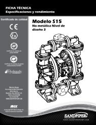
REPAIR PARTS LIST and DRAWING<br />
EB2-M EB2-MB<br />
MEB2-M EB50M<br />
Type 3<br />
ITEM<br />
TOTAL<br />
NO. PART NUMBER DESCRIPTION RQD.<br />
1 070-006-170 Bearing, Sleeve 2<br />
2 114-002-156 Bracket, Intermediate 1<br />
114-002-010 Bracket, Intermediate 1<br />
3 720-004-360 Seal, U-Cup 2<br />
4 135-008-000 Bushing, Threaded, with o-ring 2<br />
135-016-162 Bushing, Threaded, with o-ring 2<br />
(MEB2-M only)<br />
5 620-004-114 Plunger, Actuator 2<br />
620-011-114 Plunger, Actuator (MEB2-M only)<br />
6 095-073-000 Assembly, Pilot Valve* 1<br />
6-A 095-070-551 Valve Body 1<br />
6-B 755-025-000 Sleeve (with o-rings) 1<br />
6-C 560-033-360 O-Ring (Sleeve) 4<br />
6-D 775-026-000 Spool (with o-rings) 1<br />
6-E 560-023-360 O-Ring (Spool) 2<br />
6-F 675-037-080 Retaining Ring 1<br />
7 360-041-425 Gasket, Valve Body 1<br />
8 560-001-360 O-Ring 2<br />
9 095-043-156 Body, Valve 1<br />
095-043-010 Body, Valve 1<br />
10 132-014-358 Bumper, Valve Spool 2<br />
11 165-011-157 Cap, End 2<br />
165-011-010 Cap, End 2<br />
12 360-048-425 Gasket, Valve Body 1<br />
13 360-010-425 Gasket, End Cap 2<br />
14 560-020-360 O-Ring 6<br />
15 031-012-000 Sleeve & Spool Set 1<br />
16 170-032-330 Capscrew, Hex Head 8<br />
170-032-115 Capscrew, Hex Head 8<br />
17 170-045-330 Capscrew, Hex Head 4<br />
170-045-115 Capscrew, Hex Head 4<br />
18 132-002-360 Bumper, Diaphragm 2<br />
19 196-001-157 Chamber, Inner 2<br />
196-001-010 Chamber, Inner 2<br />
20 286-007-365 Diaphragm 2<br />
286-007-363 Diaphragm 2<br />
286-007-360 Diaphragm 2<br />
286-007-366 Diaphragm 2<br />
286-007-364 Diaphragm 2<br />
286-007-356 Diaphragm 2<br />
21 560-022-360 O-Ring 2<br />
22 685-007-120 Rod, Diaphragm 1<br />
23 170-023-330 Capscrew, Hex Head 16<br />
170-023-115 Capscrew, Hex Head 16<br />
24 170-024-330 Capscrew, Hex Head 8<br />
170-024-115 Capscrew, Hex Head 8<br />
25 618-003-330 Plug, Pipe (SS & Alloy C Qty.2) 4<br />
618-003-110 Plug, Pipe (SS Only) (AX Qty. 4) 2<br />
618-003-112 Plug, Pipe (Alloy C Only) 2<br />
26 900-006-330 Washer, Lock 8<br />
900-006-115 Washer, Lock 8<br />
27 612-047-330 Plate, Diaphragm 2<br />
28 612-039-157 Plate, Outer 2<br />
612-097-110 Plate, Outer 2<br />
612-039-010 Plate, Outer 2<br />
29 807-026-330 Stud 2<br />
*Available in Kit Form. Order P/N 031-055-000 which also includes<br />
items 5, 7, 12 & 47.<br />
Repair Parts shown in bold face (darker)<br />
type are more likely to need replacement<br />
after extended periods of normal use. They<br />
are readily available from most Warren<br />
Rupp distributors. The pump owner may<br />
prefer to maintain a limited inventory of<br />
these parts in his own stock to reduce repair<br />
downtime to a minimum.<br />
IMPORTANT: When ordering repair parts<br />
always furnish pump model number, serial<br />
number and type number.<br />
MATERIAL CODES<br />
The Last 3 Digits of Part Number<br />
000…Assembly, sub-assembly;<br />
and some purchased Items<br />
010…Cast Iron<br />
012…Powered Metal<br />
015…Ductile Iron<br />
020…Ferritic Malleable Iron<br />
025…Music Wire<br />
080…CarbonSteel AISI B-1112<br />
100…Alloy 20<br />
110…Alloy Type 316 Stainless Steel<br />
111…Alloy Type 316 Stainless Steel (Electro Polished)<br />
112…Alloy “C”<br />
113…Alloy Type 316 Stainless Steel (Hand Polished)<br />
114…303 Stainless Steel<br />
115…302/304 Stainless Steel<br />
117…440-C Stainless Steel (Martensitic)<br />
120…416 Stainless Steel (Wrought Martensitic)<br />
123…410 Stainless Steel (Wrought Martensitic)<br />
148…Hardcoat Anodized Aluminum<br />
149…2024-T4 Aluminum<br />
150…6061-T6 Aluminum<br />
151…6063-T6 Aluminum<br />
152…2024-T4 Aluminum (2023-T351)<br />
154…Almag 35 Aluminum<br />
155 or 156…356-T6 Aluminum<br />
157…Die Cast Aluminum Alloy #380<br />
158…Aluminum Alloy SR-319<br />
159…Anodized Aluminum<br />
162…Brass, Yellow, Screw Machine Stock<br />
165…Cast Bronze, 85-5-5-5<br />
166…Bronze SAE 660<br />
170…Bronze, Bearing Type, Oil Impregnated<br />
180…Copper Alloy<br />
310…Kynar Coated<br />
330…Zinc Plated Steel<br />
331…Chrome Plated Steel<br />
332…Electroless Nickel Plated<br />
335…Galvanized Steel<br />
336…Zinc Plated Yellow Brass<br />
337…Silver Plated Steel<br />
340…Nickel Plated<br />
342…Filled Nylon<br />
354…Injection Molded #203-40 Santoprene<br />
- Duro 40D ± 5; Color: RED<br />
355…Thermoplastic Elastomer<br />
356…Hytrel<br />
357…Rupplon (Urethane Rubber) Color<br />
coded:PURPLE<br />
358…Rupplon (Urethane Rubber)<br />
Color coded:PURPLE<br />
(Some Applications, Compression Mold)<br />
359…Urethane Rubber<br />
360…Buna-N Rubber Color coded: RED<br />
361…Buna-N<br />
363…Viton (Fluorel) Color coded: YELLOW<br />
364…E.P.D.M. Rubber Color coded: BLUE<br />
365…Neoprene Rubber Color coded: GREEN<br />
370…Butyl Rubber Color coded: BROWN<br />
371…Philthane (Tuftane)<br />
List continued next page<br />
520-035-000 2/02 Model EB2-M, EB2-MB, MEB2-M, EB50M Type 3 Page 5
ITEM<br />
TOTAL<br />
NO. PART NUMBER DESCRIPTION RQD.<br />
31 545-007-330 Nut, Hex 16<br />
545-007-115 Nut, Hex 16<br />
32 722-040-365 Seat, Valve 4<br />
722-069-360 Seat, Valve (Cast Iron Only) 4<br />
722-069-363 Seat, Valve (Cast Iron Only) 4<br />
722-069-364 Seat, Valve (Cast Iron Only) 4<br />
722-069-365 Seat, Valve (Cast Iron Only) 4<br />
722-069-600 Seat, Valve (Cast Iron Only) 4<br />
722-040-363 Seat, Valve 4<br />
722-040-360 Seat, Valve 4<br />
722-040-364 Seat, Valve 4<br />
722-040-600 Seat, Valve 4<br />
722-040-110 Seat, Valve (See NOTE Below) 2<br />
33 050-017-365 Ball, Check Valve 4<br />
050-017-360 Ball, Check Valve 4<br />
050-017-364 Ball, Check Valve 4<br />
050-018-600 Ball, Check Valve 4<br />
34 518-032-156 Manifold, Suction (NPT EB2-M Only) 1<br />
518-032-110 Manifold, Suction (NPT EB2-M Only) 1<br />
518-032-010 Manifold, Suction (NPT EB2-M Only) 1<br />
518-032-156E Manifold, Suction (BSP EB50M) 1<br />
518-032-010E Manifold, Suction (BSP EB50M) (3 Bolt) 1<br />
518-032-110E Manifold, Suction (BSP EB50M) 1<br />
35 518-033-156 Manifold, Discharge (NPT) 1<br />
518-033-110 Manifold, Discharge (NPT) 1<br />
518-033-010 Manifold, Discharge (NPT) (3 Bolt) 1<br />
518-033-156E Manifold, Discharge (BSP EB50M) 1<br />
518-033-110E Manifold, Discharge (BSP EB50M) 1<br />
518-033-010E Manifold, Discharge (BSP EB50M) 1<br />
36 902-003-000 Stat-O-Seal 2<br />
37 170-066-330 Capscrew, Hex Head. 8<br />
(EB2-MB Qty. 4)(CI Qty.12)<br />
170-066-115 Capscrew, Hex Head. 8<br />
(EB2-MB Qty. 4)(CI Qty.12)<br />
38 900-003-330 Washer, Lock (CI Qty.12) 8<br />
900-003-115 Washer, Lock (CI Qty.12) 8<br />
901-006-330 Washer, Flat (Used on CI Units) 12<br />
39 545-008-330 Nut, Hex (Not Used on CI Units) 8<br />
545-008-110 Nut, Hex (Not Used on CI Units) 8<br />
41 196-047-156 Chamber, Outer 2<br />
196-047-110 Chamber, Outer 2<br />
196-047-010 Chamber, Outer 2<br />
42 530-008-000 Muffler, Exhaust 1<br />
43 326-003-080 Mounting Feet (SS & Alloy C Only) 2<br />
44 170-024-330 Capscrew, Hex Head<br />
(SS & Alloy C Only) 4<br />
45 900-006-330 Washer, Flat (SS & Alloy C Only) 4<br />
46 286-020-604 Overlay Diaphragm 2<br />
47 132-022-360 Bumper 2<br />
48 800-012-158 Base, Strainer (EB2-MB Only) 1<br />
49 518-044-156 Manifold, Suction (EB2-MB Only) 1<br />
50 170-055-330 Capscrew, Hex Head (EB2-MB Only) 4<br />
51 258-016-158 Cover, Suction (EB2-MB Only) 1<br />
52 170-035-330 Capscrew, Hex Head (EB2-MB Only) 1<br />
53 900-006-330 Washer, Lock (EB2-MB Only) 1<br />
54 031-019-156 Main Air Valve Assembly 1<br />
(Inc. Items 9,10,11,13, 14, 15, 16)<br />
031-019-010 Main Air Valve Assembly 1<br />
031-053-156 Main Air Valve Assembly 1<br />
(EB2M, TB3AX & TN3AX units)<br />
Repair Parts shown in bold face (darker)<br />
type are more likely to need replacement<br />
after extended periods of normal use.<br />
They are readily available from most Warren<br />
Rupp distributors. The pump owner<br />
may prefer to maintain a limited inventory<br />
of these parts in his own stock to reduce<br />
repair downtime to a minimum.<br />
IMPORTANT: When ordering repair parts<br />
always furnish pump model number, serial<br />
number and type number.<br />
MATERIAL CODES<br />
The Last 3 Digits of Part Number<br />
Continued from previous page<br />
375…Fluorinated Nitrile<br />
378…High density Polypropylene<br />
405…Cellulose Fibre<br />
408…Cork and Neoprene<br />
425…Compressed Fibre<br />
426…Blue Gard<br />
440…Vegetable Fibre<br />
465…Fibre<br />
500…Delrin 500<br />
501…Delrin 570<br />
505…Acrylic Resin Plastic<br />
520…Injection Molded PVDF Natural Color<br />
540…Nylon<br />
541…Nylon<br />
542…Nylon<br />
544…Nylon Injection Molded<br />
550…Polyethylene<br />
551…Polypropylene<br />
552…Unfilled Polypropylene<br />
553…Unfilled Polypropylene<br />
555…Polyvinyl Chloride<br />
570…Rulon II<br />
580…Ryton<br />
590…Valox<br />
591…Nylatron G-S<br />
592…Nylatron NSB<br />
600…Teflon (virgin material) Tetrafluoroethylene (TFE)<br />
601…Teflon (Bronze and moly filled)<br />
602…Filled Teflon<br />
603…Blue Gylon<br />
604…Teflon<br />
606…Teflon<br />
610…Teflon Encapsulated Silicon<br />
611…Teflon Encapsulated Viton<br />
Delrin, Teflon, Viton and Hytrel are registered<br />
tradenames of E.I. DuPont.<br />
Gylon is a registered tradename of Garlock. Inc.<br />
Nylatron is a registered tradename of Polymer Corp.<br />
Rulon II is a registered tradename of Dixion Industries<br />
Corporation.<br />
Hastelloy-C is a registered tradename of Cabot Corp.<br />
Ryton is a registered tradename of Phillips Chemical<br />
Company.<br />
Valox is a registered tradename of General Electric<br />
Company.<br />
Warren Rupp, Rupplon, SandPIPER, PortaPump,<br />
Tranquilizer, and SludgeMaster are registered<br />
tradenames of Warren Rupp Inc.<br />
NOTE: For special construction pumps equipped with stainless steel check valve seat<br />
722-040-110 check the configuration of the seat o-ring groove.<br />
a) If the groove is open-end on the outer diameter order the 560-085-611 o-ring.<br />
b) If the groove is a smaller diameter with three sides order the 720-060-600 PTFE seal.<br />
Model EB2-M, EB2-MB, MEB2-M, EB50M Type 3 Page 6 520-035-000 2/02
6-D<br />
6-E<br />
6-B<br />
6-C<br />
6-F<br />
54<br />
Used on S.S.<br />
& Alloy C<br />
pumps only.<br />
Diaphragm when used with overlay.<br />
Ribs are toward pumped material.<br />
© 2002 Warren Rupp, Inc. All rights reserved.<br />
®Warren Rupp and SandPIPER are registered tradenames of Warren Rupp, Inc.<br />
Printed in U.S.A.<br />
520-035-000 2/02 Model EB2-M, EB2-MB, MEB2-M, EB50M Type 3 Page 7