Download PDF
Download PDF
Download PDF

You also want an ePaper? Increase the reach of your titles
YUMPU automatically turns print PDFs into web optimized ePapers that Google loves.
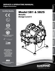
SERVICE & OPERATING MANUAL<br />
Original Instructions<br />
Certified Quality<br />
Model ST1 & ST25<br />
Containment Duty<br />
Design Level 5<br />
1: PUMP SPECS<br />
Quality System<br />
ISO 9001 Certified<br />
2: INSTAL & OP<br />
Environmental Management System<br />
ISO 14001 Certified<br />
3: EXP VIEW<br />
4: AIR END<br />
Warren Rupp, Inc.<br />
A Unit of IDEX Corporation<br />
800 N. Main St.,<br />
Mansfield, Ohio 44902 USA<br />
Telephone (419) 524.8388<br />
Fax (419) 522.7867<br />
WWW.SANDPIPERPUMP.COM<br />
5: WARRANTY<br />
©2015 Warren Rupp, Inc.<br />
www.sandpiperpump.com
Safety Information<br />
IMPORTANT<br />
WARNING<br />
Read the safety warnings and instructions in this manual<br />
before pump installation and start-up. Failure to comply with<br />
the recommendations stated in this manual could damage the<br />
pump and void factory warranty.<br />
When the pump is used for materials that tend to settle out<br />
or solidify, the pump should be flushed after each use to<br />
prevent damage. In freezing temperatures the pump should be<br />
completely drained between uses.<br />
CAUTION<br />
Before pump operation, inspect all fasteners for loosening<br />
caused by gasket creep. Retighten loose fasteners to prevent<br />
leakage. Follow recommended torques stated in this manual.<br />
Nonmetallic pumps and plastic components are not UV<br />
stabilized. Ultraviolet radiation can damage these parts and<br />
negatively affect material properties. Do not expose to UV light<br />
for extended periods of time.<br />
When used for toxic or aggressive fluids, the pump should<br />
always be flushed clean prior to disassembly.<br />
Before maintenance or repair, shut off the compressed air line,<br />
bleed the pressure, and disconnect the air line from the pump.<br />
Be certain that approved eye protection and protective clothing<br />
are worn at all times. Failure to follow these recommendations<br />
may result in serious injury or death.<br />
Airborne particles and loud noise hazards. Wear eye and ear<br />
protection.<br />
In the event of diaphragm rupture, pumped material may enter<br />
the air end of the pump, and be discharged into the atmosphere.<br />
If pumping a product that is hazardous or toxic, the air exhaust<br />
must be piped to an appropriate area for safe containment.<br />
Take action to prevent static sparking. Fire or explosion can<br />
result, especially when handling flammable liquids. The pump,<br />
piping, valves, containers and other miscellaneous equipment<br />
must be properly grounded.<br />
This pump is pressurized internally with air pressure during<br />
operation. Make certain that all fasteners are in good condition<br />
and are reinstalled properly during reassembly.<br />
Grounding the Pump<br />
To be fully groundable, the pumps must be ATEX Compliant. Refer to the nomenclature page for ordering information.<br />
Optional 8 foot long (244 centimeters) Ground Strap is available for easy ground connection.<br />
To reduce the risk of static electrical sparking, this pump must be grounded. Check the local<br />
electrical code for detailed grounding instruction and the type of equipment required.<br />
Refer to nomenclature page for ordering information.<br />
WARNING<br />
Take action to prevent static sparking.<br />
Fire or explosion can result, especially<br />
when handling flammable liquids. The<br />
pump, piping, valves, containers or<br />
other miscellaneous equipment must<br />
be grounded.<br />
Model ST1/ST25<br />
www.sandpiperpump.com<br />
st1dl5sm-rev0515
Table of Contents<br />
SECTION 1: PUMP SPECIFICATIONS................1<br />
• Explanation of Nomenclature<br />
• Performance<br />
• Materials<br />
• Dimensional Drawings<br />
SECTION 2: INSTALLATION & OPERATION......4<br />
• Principle of Pump Operation<br />
• Recommended Installation Guide<br />
• Filling the Driver Chambers with Fluid<br />
• Troubleshooting Guide<br />
1: PUMP SPECS<br />
2: INSTAL & OP<br />
SECTION 3: EXPLODED VIEW...........................7<br />
• Composite Repair Parts Drawing<br />
• Composite Repair Parts List<br />
• Material Codes<br />
3: EXP VIEW<br />
SECTION 4: AIR END.......................................11<br />
• Air Distribution Valve Assembly<br />
• Pilot Valve Assembly<br />
4: AIR END<br />
SECTION 7: WARRANTY & CERTIFICATES.....13<br />
• Warranty<br />
• CE Declaration of Conformity - Directive 2006/42/EC Machinery<br />
• ATEX Declaration of Conformity - Directive 94/9/EC<br />
• ATEX Summary of Markings<br />
5: WARRANTY<br />
www.sandpiperpump.com<br />
st1dl5sm-rev0515<br />
Model ST1/ST25
Explanation of Pump Nomenclature<br />
1: PUMP SPECS<br />
Your Model #:<br />
(fill in from pump<br />
nameplate)<br />
__ __ _____ __ ___ __ __<br />
Pump Pump Pump Size Manifold Diaphragm/ Design<br />
Series Design and Options Porting Valve Level<br />
Construction<br />
Model #: XX X XXXXXX, XX XXX X XX<br />
Pump Series<br />
S SANDPIPER ®<br />
Pump Design<br />
T Spill Containment<br />
Pump Size & Options<br />
1 1" NPT<br />
25 1" BSP Tapered<br />
Options<br />
VL Visual Leak Detection Sight Tubes<br />
Manifold Porting Position<br />
D Side<br />
Diaphragm Check Valve Materials<br />
NG Neoprene Driver Diaphragms, PTFE<br />
Pumping Diaphragms<br />
VG FKM Driver Diaphragms / PTFE<br />
Pumping Diaphragms<br />
GNG Neoprene Backup Diaphragms with PTFE<br />
Overlay Pumping Diaphragms / PTFE<br />
Pumping Diaphragms<br />
Design Level<br />
5<br />
Construction<br />
A Aluminum Wetted, Aluminum Air<br />
SS Stainless Steel Wetted, Aluminum Air<br />
HC Alloy-C Wetted, Aluminum Air<br />
Your Serial #: (fill in from pump nameplate)______________________________________<br />
ATEX Detail<br />
(1)<br />
II 2G c T5<br />
II 2GD 3/2 G T5c T5<br />
II 2D c T100°C<br />
1 • Model ST1/ST25<br />
www.sandpiperpump.com<br />
st1dl5sm-rev0515
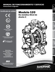
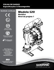
Performance<br />
ST1 & ST25 Containment Duty<br />
SUCTION/DISCHARGE PORT SIZE<br />
• ST1: 1” NPT (internal)<br />
• ST25: 1” BSP Tapered (internal)<br />
CAPACITY<br />
• 0 to 42 gallons per minute<br />
(0 to 159 liters per minute)<br />
AIR DISTRIBUTION VALVE<br />
• No-lube, no-stall design<br />
SOLIDS-HANDLING<br />
• Occational solids only,<br />
to nearly .25” (6.3mm)<br />
HEADS UP TO<br />
• 125 psi or 289 ft. of water<br />
(8.8 Kg/cm 2 or 88 meters)<br />
MAXIMUM OPERATING PRESSURE<br />
• 125 psi (8.6 bar)<br />
DISPLACEMENT/STROKE<br />
• .09 Gallon / .34 liter<br />
SHIPPING WEIGHT<br />
• Aluminum 46 lbs. (20kg)<br />
• Stainless Steel 67 lbs. (30kg)<br />
Materials<br />
Material Profile:<br />
HEAD<br />
BAR<br />
7<br />
6<br />
5<br />
4<br />
3<br />
2<br />
1<br />
0<br />
PSI<br />
100<br />
10(17)<br />
90<br />
80<br />
CAUTION! Operating temperature limitations are as follows:<br />
Conductive Acetal: Tough, impact resistant, ductile. Good<br />
abrasion resistance and low friction surface. Generally inert, with<br />
good chemical resistance except for strong acids and oxidizing<br />
agents.<br />
EPDM: Shows very good water and chemical resistance. Has<br />
poor resistance to oils and solvents, but is fair in ketones and<br />
alcohols.<br />
FKM: (Fluorocarbon) Shows good resistance to a wide range<br />
of oils and solvents; especially all aliphatic, aromatic and<br />
halogenated hydrocarbons, acids, animal and vegetable oils.<br />
Hot water or hot aqueous solutions (over 70°F(21°C)) will<br />
attack FKM.<br />
Hytrel®: Good on acids, bases, amines and glycols at room<br />
temperatures only.<br />
Neoprene: All purpose. Resistance to vegetable oils. Generally<br />
not affected by moderate chemicals, fats, greases and many<br />
oils and solvents. Generally attacked by strong oxidizing acids,<br />
ketones, esters and nitro hydrocarbons and chlorinated aromatic<br />
hydrocarbons.<br />
Nitrile: General purpose, oil-resistant. Shows good solvent, oil,<br />
water and hydraulic fluid resistance. Should not be used with<br />
highly polar solvents like acetone and MEK, ozone, chlorinated<br />
hydrocarbons and nitro hydrocarbons.<br />
Nylon: 6/6 High strength and toughness over a wide<br />
temperature range. Moderate to good resistance to fuels, oils<br />
and chemicals.<br />
100 PSI<br />
80 PSI<br />
15(25.4)<br />
20(34)<br />
25(42.5)<br />
30(51)<br />
70<br />
35(59.5)<br />
60<br />
40(68)<br />
50<br />
45(76.5)<br />
40<br />
50(85)<br />
30<br />
20<br />
10<br />
0<br />
0 4 8 12 16 20 24 28 32 36 40<br />
US Gallons per minute<br />
60 PSI<br />
40 PSI<br />
AIR CONSUMPTION<br />
SCFM (M 3 /hr)<br />
20 PSI Air Inlet Pressure<br />
MODEL ST1/ST25 Performance Curve<br />
Performance based on the following: elastomer fitted pump, flooded suction,<br />
water at ambient conditions. The use of other materials and varying hydraulic<br />
conditions may result in deviations in excess of 5%.<br />
0 20 40 60 80 100 120 140 150<br />
Operating<br />
Temperatures:<br />
Max. Min.<br />
190°F<br />
88°C<br />
280°F<br />
138°C<br />
350°F<br />
177°C<br />
220°F<br />
104°C<br />
200°F<br />
93°C<br />
190°F<br />
88°C<br />
180°F<br />
82°C<br />
-20°F<br />
-29°C<br />
-40°F<br />
-40°C<br />
-40°F<br />
-40°C<br />
-20°F<br />
-29°C<br />
-10°F<br />
-23°C<br />
-10°F<br />
-23°C<br />
32°F<br />
0°C<br />
Liters per minute<br />
CAPACITY<br />
Polypropylene: A thermoplastic polymer. Moderate tensile<br />
and flex strength. Resists stong acids and alkali. Attacked by<br />
chlorine, fuming nitric acid and other strong oxidizing agents.<br />
PVDF: (Polyvinylidene Fluoride) A durable fluoroplastic with<br />
excellent chemical resistance. Excellent for UV applications.<br />
High tensile strength and impact resistance.<br />
Santoprene®: Injection molded thermoplastic elastomer with<br />
no fabric layer. Long mechanical flex life. Excellent abrasion<br />
resistance.<br />
UHMW PE: A thermoplastic that is highly resistant to a broad<br />
range of chemicals. Exhibits outstanding abrasion and impact<br />
resistance, along with environmental stress-cracking resistance.<br />
Urethane: Shows good resistance to abrasives. Has poor<br />
resistance to most solvents and oils.<br />
Virgin PTFE: (PFA/TFE) Chemically inert, virtually impervious.<br />
Very few chemicals are known to chemically react with PTFE;<br />
molten alkali metals, turbulent liquid or gaseous fluorine and<br />
a few fluoro-chemicals such as chlorine trifluoride or oxygen<br />
difluoride which readily liberate free fluorine at elevated<br />
temperatures.<br />
180°F<br />
82°C<br />
250°F<br />
121°C<br />
275°F<br />
135°C<br />
180°F<br />
82°C<br />
150°F<br />
66°C<br />
220°F<br />
104°C<br />
32°F<br />
0°C<br />
0°F<br />
-18°C<br />
-40°F<br />
-40°C<br />
-35°F<br />
-37°C<br />
32°F<br />
0°C<br />
-35°F<br />
-37°C<br />
Maximum and Minimum Temperatures are the limits for which these materials can be operated.<br />
Temperatures coupled with pressure affect the longevity of diaphragm pump components.<br />
Maximum life should not be expected at the extreme limits of the temperature ranges.<br />
Metals:<br />
Alloy C: Equal to ASTM494 CW-12M-1 specification for nickel and nickel alloy.<br />
Stainless Steel: Equal to or exceeding ASTM specification A743 CF-8M for corrosion<br />
resistant iron chromium, iron chromium nickel and nickel based alloy castings for<br />
general applications. Commonly referred to as 316 Stainless Steel in the pump industry.<br />
For specific applications, always consult the Chemical Resistance Chart.<br />
Ambient temperature range: -20°C to +40°C<br />
Process temperature range: -20°C to +80°C for models rated as category 1 equipment<br />
-20°C to +100°C for models rated as category 2 equipment<br />
In addition, the ambient temperature range and the process temperature range do not exceed the operating temperature range of the applied non-metallic parts as listed in the manuals of the pumps.<br />
1: PUMP SPECS<br />
www.sandpiperpump.com Model ST1/ST25 • 2<br />
st1dl5sm-rev0515
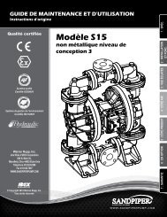
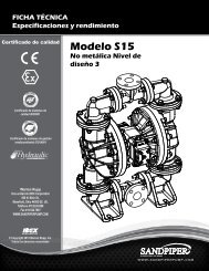
Dimensional Drawings<br />
1: PUMP SPECS<br />
ST1 & ST25 Containment Duty<br />
Dimensions are ±1/8". Figures in parentheses = millimeters.<br />
14.60<br />
371<br />
14.26<br />
362<br />
DISCHARGE PORT<br />
1" NPT (ST1)<br />
1" BSPT (ST25)<br />
8.82<br />
224<br />
7.12<br />
181<br />
5.54<br />
141<br />
4.10<br />
104<br />
15.50<br />
394<br />
12.52<br />
318<br />
8.57<br />
218<br />
4.61<br />
117<br />
SUCTION PORT<br />
1" NPT (ST1)<br />
1" BSPT (ST25)<br />
6.89<br />
175<br />
8.56<br />
217<br />
9.75<br />
248<br />
.72<br />
18<br />
9.00<br />
229<br />
10.19<br />
259<br />
4X .28 MOUNTING HOLE<br />
7<br />
NOTE:<br />
UNIT FURNISHED WITH SUB-BASE PLATE<br />
AND RUBBER FEET AS STANDARD FOR<br />
STATIONARY BOLT DOWN USE, RUBBER<br />
FEET CAN BE REMOVED<br />
9.00<br />
229<br />
8.56<br />
217<br />
3 • Model ST1/ST25<br />
www.sandpiperpump.com<br />
st1dl5sm-rev0515
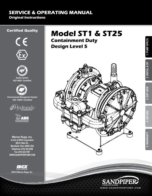
Principle of Pump Operation<br />
Air-Operated Double Diaphragm (AODD) pumps are powered<br />
by compressed air or nitrogen.<br />
Air Line<br />
Discharged<br />
Fluid<br />
The main directional (air) control valve 1 distributes<br />
compressed air to an air chamber, exerting uniform pressure<br />
over the inner surface of the diaphragm 2. At the same time,<br />
the exhausting air 3 from behind the opposite diaphragm<br />
is directed through the air valve assembly(s) to an exhaust<br />
port 4.<br />
As inner chamber pressure (P1) exceeds liquid chamber<br />
pressure (P2), the rod 5 connected diaphragms shift<br />
together creating discharge on one side and suction on the<br />
opposite side. The discharged and primed liquid’s directions<br />
are controlled by the check valves (ball or flap)6 orientation.<br />
The pump primes as a result of the suction stroke. The<br />
suction stroke lowers the chamber pressure (P3) increasing<br />
the chamber volume. This results in a pressure differential<br />
necessary for atmospheric pressure (P4) to push the fluid<br />
through the suction piping and across the suction side check<br />
valve and into the outer fluid chamber 7.<br />
2: INSTAL & OP<br />
Discharge<br />
Stroke<br />
Suction<br />
Stroke<br />
PUMP INSTALLATION AREA<br />
Suction (side) stroking also initiates the reciprocating SAFE AIR<br />
EXHAUST<br />
(shifting, stroking or cycling) action of the pump. DISPOSAL The suction<br />
diaphragm’s movement is mechanically pulled through AREA its<br />
1" DIAMETER stroke. AIR The diaphragm’s inner plate makes contact with an<br />
EXHAUST PIPING actuator plunger aligned to shift the pilot signaling valve.<br />
Once actuated, the pilot valve sends a pressure MUFFLER signal to the<br />
opposite end of the main directional air valve, redirecting the<br />
compressed air to the opposite inner chamber.<br />
Primed<br />
Fluid<br />
SUBMERGED ILLUSTRATION<br />
MUFFLER<br />
LIQUID<br />
LEVEL<br />
1" DIAMETER AIR<br />
EXHAUST PIPING<br />
SUCTION<br />
LINE<br />
Pump can be submerged if the pump materials of construction<br />
are compatible with the liquid being pumped. The air exhaust<br />
must be piped above the liquid level. When the MUFFLER pumped product<br />
source is at a higher level than the pump (flooded suction<br />
condition), pipe the exhaust higher than the product source to<br />
prevent siphoning spills.<br />
LIQUID<br />
LEVEL<br />
1" DIAMETER AIR<br />
EXHAUST PIPING<br />
SUCTION<br />
www.sandpiperpump.com<br />
LINE<br />
Model ST1/ST25 • 4<br />
st1dl5sm-rev0515
Recommended Installation Guide<br />
Available Accessories:<br />
1. Surge Suppressor<br />
2. Filter/Regulator<br />
3. Air Dryer<br />
Unregulated Air<br />
Supply to Surge<br />
Suppressor<br />
1<br />
Surge Suppressor<br />
Pressure Gauge<br />
2: INSTAL & OP<br />
Note: Surge Suppressor and<br />
Piping must be supported after<br />
the flexible connection<br />
Pipe Connection<br />
(Style Optional)<br />
Flexible Connector<br />
Shut-Off Valve<br />
Discharge<br />
Check<br />
Valve<br />
Muffler<br />
(Optional Piped Exhaust)<br />
Drain Port<br />
Shut-Off<br />
Valve<br />
Flexible Connector<br />
2<br />
Air Inlet<br />
Vacuum<br />
Gauge<br />
Flexible<br />
Connector<br />
3<br />
Filter Regulator<br />
P/N: 020.V107.000<br />
Suction<br />
Shut-Off Valve<br />
Drain Port<br />
Pipe Connection<br />
(Style Optional)<br />
Air Dryer<br />
Note: Pipe weight should not be supported<br />
by pump connections.<br />
CAUTION<br />
The air exhaust should<br />
be piped to an area<br />
for safe disposition<br />
of the product being<br />
pumped, in the event of<br />
a diaphragm failure.<br />
Installation And Start-Up<br />
Locate the pump as close to the product being pumped as possible. Keep the suction line length and number of fittings to a minimum. Do not reduce the suction line<br />
diameter.<br />
Air Supply<br />
Connect the pump air inlet to an air supply with sufficient capacity and pressure to achieve desired performance. A pressure regulating valve should be installed to<br />
insure air supply pressure does not exceed recommended limits.<br />
Air Valve Lubrication<br />
The air distribution system is designed to operate WITHOUT lubrication. This is the standard mode of operation. If lubrication is desired, install an air line lubricator<br />
set to deliver one drop of SAE 10 non-detergent oil for every 20 SCFM (9.4 liters/sec.) of air the pump consumes. Consult the Performance Curve to determine air<br />
consumption.<br />
Air Line Moisture<br />
Water in the compressed air supply may cause icing or freezing of the exhaust air, causing the pump to cycle erratically or stop operating. Water in the air supply can<br />
be reduced by using a point-of-use air dryer.<br />
Air Inlet And Priming<br />
To start the pump, slightly open the air shut-off valve. After the pump primes, the air valve can be opened to increase air flow as desired. If opening the valve<br />
increases cycling rate, but does not increase the rate of flow, cavitation has occurred. The valve should be closed slightly to obtain the most efficient air flow to pump<br />
flow ratio.<br />
5 • Model ST1/ST25<br />
www.sandpiperpump.com<br />
st1dl5sm-rev0515
Filling the Driver Chambers with Liquid<br />
THE DRIVER CHAMBERS WILL BE<br />
FILLED WITH DISTILLED WATER AT<br />
THE FACTORY.<br />
If you need to substitute another liquid to prevent<br />
system contamination, first consult the factory for<br />
chemical compatibility with pump construction.<br />
Step 6. When the driver fluid rises to the top<br />
of the fill plug hole, apply pipe dope to the pipe<br />
plug, and thread it into the chamber plug hole.<br />
(Do not use PTFE tape.) Keep pressure on the<br />
PTFE diaphragm until the pipe plug is tight to<br />
prevent air from drawing<br />
back into the chamber.<br />
Follow the steps listed below to replace the liquid<br />
in the pump after disassembly or liquid loss:<br />
Step 1. Filling is accomplished through the<br />
pipe plugs at the top of the liquid chamber. Drain<br />
ports are at the bottom of the liquid chamber.<br />
Step 2. After the driver fluid has been<br />
emptied from the pump, the driver<br />
diaphragms will naturally come to center.<br />
Step 3. Remove the entire manifold assembly<br />
exposing the ports in the outer diaphragm<br />
chambers.<br />
Step 4. For pumps not equipped with Visual<br />
Leak Detection sight tubes, fill with 722ml/ 24.6<br />
fl. oz.<br />
For pumps equipped with Visual Leak Detection<br />
sight tubes, fill with 752ml/ 25.4 fl. oz.<br />
It is imperative that the driver liquid chambers<br />
be filled with the correct amount of driver liquid<br />
as too little or too much will cause premature<br />
diaphragm failure and erratic pumping.<br />
Step 5. After filling with the proper amount of<br />
liquid, if the liquid does not come to the top of<br />
the fill hole, pressure should be applied to the<br />
PTFE diaphragm with a blunt tool through the<br />
material flow port in the outer chamber until the<br />
liquid comes to the top. If the main air valve body<br />
and pilot valve are removed, the diaphragm rod<br />
will be visible in the intermediate bracket. The<br />
hole in the diaphragm rod will assist manual<br />
movement. Use a long taper punch to move the<br />
diaphragm rod.<br />
Step 7. Repeat the filling procedure for<br />
opposite side.<br />
2: INSTAL & OP<br />
www.sandpiperpump.com Model ST1/ST25 • 6<br />
st1dl5sm-rev0515
2: INSTAL & OP<br />
Troubleshooting Guide<br />
Symptom: Potential Cause(s): Recommendation(s):<br />
Pump Cycles Once<br />
Pump Will Not Operate<br />
/ Cycle<br />
Pump Cycles and Will<br />
Not Prime or No Flow<br />
Pump Cycles Running<br />
Sluggish / Stalling,<br />
Flow Unsatisfactory<br />
Product Leaking<br />
Through Exhaust<br />
Premature Diaphragm<br />
Failure<br />
Deadhead (system pressure meets or exceeds air<br />
supply pressure).<br />
Increase the inlet air pressure to the pump. Pump is designed for 1:1 pressure ratio at zero flow.<br />
(Does not apply to high pressure 2:1 units).<br />
Air valve or intermediate gaskets installed incorrectly. Install gaskets with holes properly aligned.<br />
Bent or missing actuator plunger.<br />
Remove pilot valve and inspect actuator plungers.<br />
Pump is over lubricated.<br />
Set lubricator on lowest possible setting or remove. Units are designed for lube free operation.<br />
Lack of air (line size, PSI, CFM).<br />
Check the air line size and length, compressor capacity (HP vs. cfm required).<br />
Check air distribution system.<br />
Disassemble and inspect main air distribution valve, pilot valve and pilot valve actuators.<br />
Discharge line is blocked or clogged manifolds. Check for inadvertently closed discharge line valves. Clean discharge manifolds/piping.<br />
Deadhead (system pressure meets or exceeds air Increase the inlet air pressure to the pump. Pump is designed for 1:1 pressure ratio at zero flow.<br />
supply pressure).<br />
(Does not apply to high pressure 2:1 units).<br />
Blocked air exhaust muffler.<br />
Remove muffler screen, clean or de-ice, and re-install.<br />
Pumped fluid in air exhaust muffler.<br />
Disassemble pump chambers. Inspect for diaphragm rupture or loose diaphragm plate assembly.<br />
Pump chamber is blocked.<br />
Disassemble and inspect wetted chambers. Remove or flush any obstructions.<br />
Cavitation on suction side.<br />
Check suction condition (move pump closer to product).<br />
Check valve obstructed. Valve ball(s) not seating Disassemble the wet end of the pump and manually dislodge obstruction in the check valve pocket.<br />
properly or sticking.<br />
Clean out around valve ball cage and valve seat area. Replace valve ball or valve seat if damaged.<br />
Use heavier valve ball material.<br />
Valve ball(s) missing (pushed into chamber or<br />
Worn valve ball or valve seat. Worn fingers in valve ball cage (replace part). Check Chemical<br />
manifold).<br />
Resistance Guide for compatibility.<br />
Valve ball(s) / seat(s) damaged or attacked by product. Check Chemical Resistance Guide for compatibility.<br />
Check valve and/or seat is worn or needs adjusting. Inspect check valves and seats for wear and proper setting. Replace if necessary.<br />
Suction line is blocked.<br />
Remove or flush obstruction. Check and clear all suction screens or strainers.<br />
Excessive suction lift.<br />
For lifts exceeding 20’ of liquid, filling the chambers with liquid will prime the pump in most cases.<br />
Suction side air leakage or air in product.<br />
Visually inspect all suction-side gaskets and pipe connections.<br />
Pumped fluid in air exhaust muffler.<br />
Disassemble pump chambers. Inspect for diaphragm rupture or loose diaphragm plate assembly.<br />
Over lubrication.<br />
Set lubricator on lowest possible setting or remove. Units are designed for lube free operation.<br />
Icing.<br />
Remove muffler screen, de-ice, and re-install. Install a point of use air drier.<br />
Clogged manifolds.<br />
Clean manifolds to allow proper air flow.<br />
Deadhead (system pressure meets or exceeds air<br />
supply pressure).<br />
Cavitation on suction side.<br />
Lack of air (line size, PSI, CFM).<br />
Excessive suction lift.<br />
Air supply pressure or volume exceeds system hd.<br />
Undersized suction line.<br />
Restrictive or undersized air line.<br />
Suction side air leakage or air in product.<br />
Suction line is blocked.<br />
Pumped fluid in air exhaust muffler.<br />
Check valve obstructed.<br />
Check valve and/or seat is worn or needs adjusting.<br />
Entrained air or vapor lock in chamber(s).<br />
Diaphragm failure, or diaphragm plates loose.<br />
Diaphragm stretched around center hole or bolt holes.<br />
Cavitation.<br />
Excessive flooded suction pressure.<br />
Misapplication (chemical/physical incompatibility).<br />
Incorrect diaphragm plates or plates on backwards,<br />
installed incorrectly or worn.<br />
Increase the inlet air pressure to the pump. Pump is designed for 1:1 pressure ratio at zero flow.<br />
(Does not apply to high pressure 2:1 units).<br />
Check suction (move pump closer to product).<br />
Check the air line size, length, compressor capacity.<br />
For lifts exceeding 20’ of liquid, filling the chambers with liquid will prime the pump in most cases.<br />
Decrease inlet air (press. and vol.) to the pump. Pump is cavitating the fluid by fast cycling.<br />
Meet or exceed pump connections.<br />
Install a larger air line and connection.<br />
Visually inspect all suction-side gaskets and pipe connections.<br />
Remove or flush obstruction. Check and clear all suction screens or strainers.<br />
Disassemble pump chambers. Inspect for diaphragm rupture or loose diaphragm plate assembly.<br />
Disassemble the wet end of the pump and manually dislodge obstruction in the check valve pocket.<br />
Inspect check valves and seats for wear and proper setting. Replace if necessary.<br />
Purge chambers through tapped chamber vent plugs. Purging the chambers of air can be dangerous.<br />
Replace diaphragms, check for damage and ensure diaphragm plates are tight.<br />
Check for excessive inlet pressure or air pressure. Consult Chemical Resistance Chart for compatibility<br />
with products, cleaners, temperature limitations and lubrication.<br />
Enlarge pipe diameter on suction side of pump.<br />
Move pump closer to product. Raise pump/place pump on top of tank to reduce inlet pressure.<br />
Install Back pressure device (Tech bulletin 41r). Add accumulation tank or pulsation dampener.<br />
Consult Chemical Resistance Chart for compatibility with products, cleaners, temperature limitations<br />
and lubrication.<br />
Check Operating Manual to check for correct part and installation. Ensure outer plates have not been<br />
worn to a sharp edge.<br />
Unbalanced Cycling Excessive suction lift. For lifts exceeding 20’ of liquid, filling the chambers with liquid will prime the pump in most cases.<br />
Undersized suction line.<br />
Meet or exceed pump connections.<br />
Pumped fluid in air exhaust muffler.<br />
Suction side air leakage or air in product.<br />
Check valve obstructed.<br />
Check valve and/or seat is worn or needs adjusting.<br />
Entrained air or vapor lock in chamber(s).<br />
Disassemble pump chambers. Inspect for diaphragm rupture or loose diaphragm plate assembly.<br />
Visually inspect all suction-side gaskets and pipe connections.<br />
Disassemble the wet end of the pump and manually dislodge obstruction in the check valve pocket.<br />
Inspect check valves and seats for wear and proper setting. Replace if necessary.<br />
Purge chambers through tapped chamber vent plugs.<br />
For additional troubleshooting tips contact After Sales Support at service.warrenrupp@idexcorp.com or 419-524-8388<br />
7 • Model ST1/ST25<br />
www.sandpiperpump.com<br />
st1dl5sm-rev0515
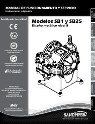
Composite Repair Parts Drawing<br />
35<br />
22<br />
32<br />
Note: Usual installation for the outer chamber and<br />
manifold is 180° from the view shown.<br />
12<br />
62<br />
30<br />
4<br />
31<br />
1<br />
10<br />
60<br />
62<br />
14<br />
23<br />
15<br />
20<br />
37<br />
25<br />
17<br />
63<br />
16<br />
26<br />
2<br />
33<br />
54<br />
33<br />
26<br />
5<br />
47<br />
40<br />
34<br />
59<br />
38<br />
13<br />
6<br />
27<br />
48<br />
49<br />
8<br />
38<br />
42<br />
45<br />
51<br />
3<br />
9<br />
21<br />
59<br />
52 44<br />
46<br />
41<br />
50<br />
38<br />
53<br />
61<br />
PTFE OVERLAY<br />
CONFIGURATION<br />
7<br />
43<br />
23<br />
43<br />
3: EXP VIEW<br />
58<br />
56<br />
36<br />
19<br />
29<br />
24<br />
18<br />
57<br />
55<br />
38<br />
59<br />
36<br />
56<br />
Service & Repair Kits<br />
58<br />
46<br />
28<br />
11<br />
45<br />
476.130.000 AIR END KIT<br />
Sleeve and Spool Set, Seals, Gaskets, O-rings,Bumpers,<br />
Plunger Actuators, Plunger Bushings, Retaining Rings, and<br />
Pilot Valve Assembly<br />
476.317.000 AIR END WEAR KIT<br />
Seals, Gaskets, O-rings, Grease Packet Bumpers, Plunger<br />
Actuators, Plunger Bushings and Retaining Rings<br />
476.039.635 WET END KIT<br />
Neoprene Driver Diaphragms, PTFE Pumping Diaphragms,<br />
PTFE Check Balls, PTFE Gaskets, Copper Washers, and<br />
Neoprene Diaphragm Gaskets<br />
476.039.637 WET END KIT<br />
FKM Driver Diaphragms, PTFE Pumping Diaphragms,<br />
PTFE Check Balls, PTFE Gaskets, Copper Washers,<br />
and FKM Diaphragm Gaskets<br />
476.039.640 WET END KIT<br />
Neoprene Driver Diaphragms, PTFE Overlay Diaphragms,<br />
PTFE Pumping Diaphragms, PTFE Check Balls, PTFE<br />
Gaskets, Copper Washers, and Neoprene Diaphragm Gaskets<br />
IMPORTANT NOTE: Polypropylene pumps are shipped with the 1/2" NPT Pipe Plug installed in the end ports of both suction and discharge one-piece<br />
manifolds. To convert to the Inline porting positions for pump installation and operation, first remove the pipe plugs and re-install in the center ports.<br />
Apply PTFE tape or pipe sealant to threads of the plug before installation.<br />
www.sandpiperpump.com Model ST1/ST25 • 8<br />
st1dl5sm-rev0515
Composite Repair Parts List<br />
3: EXP VIEW<br />
Item Part Number Description Qty. Item Part Number Description Qty.<br />
1 031.111.557 ASSEMBLY, AIR VALVE 1<br />
2 050.011.600 BALL, CHECK 4<br />
3 070.012.170 BEARING, SLEEVE 2<br />
4 095.074.001 PILOT VALVE ASSEMBLY 1<br />
5 114.007.157 INTERMEDIATE 1<br />
6 115.071.330 BRACKET, MOUNTING 1<br />
7 132.019.360 BUMPER 2<br />
8 132.022.360 BUMPER, ACTUATOR 2<br />
9 135.034.506 BUSHING, PLUNGER 2<br />
10 165.134.157 CAP, AIR INLET, ASS'Y 1<br />
10.1 165.042.157 CAP, AIR INLET 1<br />
10.2 559.017.506 ORIFICE 1<br />
11 170.029.115 CAPSCREW, HEX HD, 5/16-18 X 1.50 16<br />
12 170.043.115 CAPSCREW, HEX HD, 1/4-20 X 1.00 6<br />
13 170.045.115 CAPSCREW, HEX HEAD 5/16-18 X 1 1/4 4<br />
14 170.063.330 CAPSCREW, HEX HD, 1/4-20 X 1.75 1<br />
15 170.033.115 CAPSCREW, HEX HD, 3/8-16 UNC X 3.00 4<br />
16 170.122.115 CAPSCREW, HEX HD, 5/16-18 X 5.00 6<br />
17 171.010.115 CAPSCREW, FLANGE LOCK, 3/8-16 UNC X 1.75 4<br />
18 196.021.110 CHAMBER, OUTER 2<br />
18 196.021.112 CHAMBER, OUTER 2<br />
19 196.022.156 CHAMBER, OUTER 2<br />
20 196.042.157 CHAMBER, INNER 1<br />
21 196.043.157 CHAMBER, INNER 1<br />
22 255.012.335 COUPLING, PIPE, 3/4 NPT 1<br />
23 286.008.363 DIAPHRAGM 2<br />
286.008.365 DIAPHRAGM 2<br />
24 286.009.604 DIAPHRAGM, PUMPING 2<br />
25 286.015.604 DIAPHRAGM, OVERLAY 2<br />
26 334.013.110 FLANGE, PORTING 2<br />
334.013.112 FLANGE, PORTING 2<br />
334.013.157 FLANGE, PORTING 2<br />
334.013.110 E FLANGE, PORTING - BSP TAPERED 2<br />
334.013.112 E FLANGE, PORTING - BSP TAPERED 2<br />
334.013.157 E FLANGE, PORTING - BSP TAPERED 2<br />
27 350.002.360 FOOT, RUBBER 4<br />
28 360.030.600 GASKET, MANIFOLD 2<br />
29 360.039.363 GASKET, DIAPHRAGM 2<br />
360.039.365 GASKET, DIAPHRAGM 2<br />
30 360.056.379 GASKET 1<br />
31 360.057.360 GASKET 1<br />
32 360.058.360 GASKET 1<br />
33 360.115.608 GASKET, FLANGE 4<br />
34 518.020.110 MANIFOLD 1<br />
518.020.112 MANIFOLD 1<br />
35 530.036.000 MUFFLER 1<br />
36 538.083.110 NIPPLE, PIPE, 1/4" NPT, CLOSE 4<br />
37 542.001.115 NUT, SQUARE 1<br />
38 545.004.115 NUT, HEX, 5/16-18 42<br />
39 545.005.330 NUT, HEX 1<br />
40 547.002.110 NUT, STOP 4<br />
41 560.001.360 O-RING 2<br />
42 560.040.360 O-RING 2<br />
43 612.022.330 PLATE, DIAPHRAGM, INNER 2<br />
44 612.101.110 ASSEMBLY, DIAPHRAGM PLATE 2<br />
612.101.112 ASSEMBLY, DIAPHRAGM PLATE 2<br />
612.108.157 ASSEMBLY, DIAPHRAGM PLATE 2<br />
45 618.003.110 PLUG, PIPE, 1/4 4<br />
618.003.112 PLUG, PIPE, 1/4 4<br />
46 618.003.110 PLUG, PIPE, 1/4 6<br />
47 618.003.330 PLUG, PIPE, 1/4 1<br />
48 620.007.114 PLUNGER, ACTUATOR 2<br />
49 675.040.360 RING, SEALING 2<br />
50 675.042.115 RING, RETAINING 2<br />
51 685.039.120 ROD, DIAPHRAGM 1<br />
52 706.013.330 SCREW, MACHINE 4<br />
53 720.010.375 SEAL, U-CUP 2<br />
54 722.102.110 SEAT, CHECK VALVE 2<br />
722.102.112 SEAT, CHECK VALVE 2<br />
55 807.024.115 STUD, 5/16-18 16<br />
56 835.005.110 TEE, PIPE, 1/4 NPT 4<br />
57 860.065.606 TUBE 2<br />
58 866.060.110 CONNECTOR, TUBE 4<br />
59 900.004.115 WASHER, LOCK, 5/16 26<br />
60 901.005.115 WASHER, FLAT, 3/8 4<br />
61 901.012.180 WASHER, SEALING 2<br />
62 901.035.115 WASHER, FLAT, 1/4 7<br />
63 905.001.015 WASHER, TAPER 4<br />
LEGEND:<br />
= Items contained within Air End Kits<br />
= Items contianed within Wet End Kits<br />
Note: Kits contain components specific to the material codes.<br />
9 • Model ST1/ST25<br />
www.sandpiperpump.com<br />
st1dl5sm-rev0515
Material Codes - The Last 3 Digits of Part Number<br />
000.....Assembly, sub-assembly;<br />
and some purchased items<br />
010.....Cast Iron<br />
015.....Ductile Iron<br />
020.....Ferritic Malleable Iron<br />
080.....Carbon Steel, AISI B-1112<br />
110 .....Alloy Type 316 Stainless Steel<br />
111 .....Alloy Type 316 Stainless Steel<br />
(Electro Polished)<br />
112 .....Alloy C<br />
113 .....Alloy Type 316 Stainless Steel<br />
(Hand Polished)<br />
114 .....303 Stainless Steel<br />
115 .....302/304 Stainless Steel<br />
117 .....440-C Stainless Steel (Martensitic)<br />
120.....416 Stainless Steel<br />
(Wrought Martensitic)<br />
148.....Hardcoat Anodized Aluminum<br />
150.....6061-T6 Aluminum<br />
152.....2024-T4 Aluminum (2023-T351)<br />
155.....356-T6 Aluminum<br />
156.....356-T6 Aluminum<br />
157.....Die Cast Aluminum Alloy #380<br />
158.....Aluminum Alloy SR-319<br />
162.....Brass, Yellow, Screw Machine Stock<br />
165.....Cast Bronze, 85-5-5-5<br />
166.....Bronze, SAE 660<br />
170.....Bronze, Bearing Type,<br />
Oil Impregnated<br />
180.....Copper Alloy<br />
305.....Carbon Steel, Black Epoxy Coated<br />
306.....Carbon Steel, Black PTFE Coated<br />
307.....Aluminum, Black Epoxy Coated<br />
308.....Stainless Steel, Black PTFE Coated<br />
309.....Aluminum, Black PTFE Coated<br />
313.....Aluminum, White Epoxy Coated<br />
330.....Zinc Plated Steel<br />
332.....Aluminum, Electroless Nickel Plated<br />
333.....Carbon Steel, Electroless<br />
Nickel Plated<br />
335.....Galvanized Steel<br />
337.....Silver Plated Steel<br />
351.....Food Grade Santoprene ®<br />
353.....Geolast; Color: Black<br />
354.....Injection Molded #203-40<br />
Santoprene ® Duro 40D +/-5;<br />
Color: RED<br />
356.....Hytrel ®<br />
357.....Injection Molded Polyurethane<br />
358.....Urethane Rubber<br />
(Some Applications)<br />
(Compression Mold)<br />
359.....Urethane Rubber<br />
360.....Nitrile Rubber Color coded: RED<br />
363.....FKM (Fluorocarbon)<br />
Color coded: YELLOW<br />
364.....EPDM Rubber<br />
Color coded: BLUE<br />
365.....Neoprene Rubber<br />
Color coded: GREEN<br />
366.....Food Grade Nitrile<br />
368.....Food Grade EPDM<br />
371.....Philthane (Tuftane)<br />
374.....Carboxylated Nitrile<br />
375.....Fluorinated Nitrile<br />
378.....High Density Polypropylene<br />
379.....Conductive Nitrile<br />
408.....Cork and Neoprene<br />
425.....Compressed Fibre<br />
426.....Blue Gard<br />
440.....Vegetable Fibre<br />
500.....Delrin ® 500<br />
502.....Conductive Acetal, ESD-800<br />
503.....Conductive Acetal, Glass-Filled<br />
506.....Delrin ® 150<br />
520.....Injection Molded PVDF<br />
Natural color<br />
540.....Nylon<br />
542.....Nylon<br />
544.....Nylon Injection Molded<br />
550.....Polyethylene<br />
551.....Glass Filled Polypropylene<br />
552.....Unfilled Polypropylene<br />
555.....Polyvinyl Chloride<br />
556.....Black Vinyl<br />
557.....Conductive Carbon-filled Polypropylene<br />
558.....Conductive HDPE<br />
570.....Rulon II ®<br />
580.....Ryton ®<br />
600.....PTFE (virgin material)<br />
Tetrafluorocarbon (TFE)<br />
603.....Blue Gylon ®<br />
604.....PTFE<br />
606.....PTFE<br />
607.....Envelon<br />
608.....Conductive PTFE<br />
610.....PTFE Encapsulated Silicon<br />
611 .....PTFE Encapsulated FKM<br />
632.....Neoprene/Hytrel ®<br />
633.....FKM/PTFE<br />
634.....EPDM/PTFE<br />
635.....Neoprene/PTFE<br />
637.....PTFE, FKM/PTFE<br />
638.....PTFE, Hytrel ® /PTFE<br />
639.....Nitrile/TFE<br />
643.....Santoprene ® /EPDM<br />
644.....Santoprene ® /PTFE<br />
656 .....Santoprene ® Diaphragm and<br />
Check Balls/EPDM Seats<br />
661.....EPDM/Santoprene ®<br />
666.....FDA Nitrile Diaphragm,<br />
PTFE Overlay, Balls, and Seals<br />
668.....PTFE, FDA Santoprene ® /PTFE<br />
• Delrin and Hytrel are registered<br />
tradenames of E.I. DuPont.<br />
• Nylatron is a registered tradename<br />
of Polymer Corp.<br />
• Gylon is a registered tradename<br />
of Garlock, Inc.<br />
• Santoprene is a registered tradename<br />
of Exxon Mobil Corp.<br />
• Rulon II is a registered tradename<br />
of Dixion Industries Corp.<br />
• Ryton is a registered tradename<br />
of Phillips Chemical Co.<br />
• Valox is a registered tradename<br />
of General Electric Co.<br />
RECYCLING<br />
Many components of SANDPIPER ® AODD<br />
pumps are made of recyclable materials.<br />
We encourage pump users to recycle worn<br />
out parts and pumps whenever possible,<br />
after any hazardous pumped fluids are<br />
thoroughly flushed.<br />
3: EXP VIEW<br />
www.sandpiperpump.com Model ST1/ST25 • 10<br />
st1dl5sm-rev0515
Air Distribution Valve Assembly<br />
With Cast Iron Center<br />
1G<br />
1E<br />
1F<br />
1C<br />
1D<br />
1B<br />
1H<br />
1A<br />
4: AIR END<br />
1C<br />
1D<br />
1C<br />
1F<br />
1E<br />
1G<br />
Air Distribution Valve Servicing<br />
See repair parts drawing above.<br />
Step 1: Remove end cap retainer (1G).<br />
Step 2: Remove end cap (1E), bumper (1D) and o-rings (1C and 1F).<br />
Step 3: Remove spool part of (1A) (caution, do not scratch).<br />
Step 4: Press sleeve (1A) from body (1B).<br />
Step 5: Inspect O-Ring (1C) and replace if necessary.<br />
Step 6: Lightly lubricate O-Rings (1D) on spool (1A).<br />
Step 7: Press sleeve (1A) into body (1B).<br />
Step 8: Reassemble in reverse order.<br />
Note: Sleeve and spool (1A) set is match ground to a specified clearance<br />
sleeve and spools (1A) cannot be interchanged.<br />
Main Air Valve Assembly Parts List<br />
Item Part Number Description Qty<br />
1 031.111.557 Air Valve Assembly 1<br />
1.A 031.083.000 Sleeve and Spool Set with Pins 1<br />
1.B 095.051.557 Air Valve Body 1<br />
1.C 560.058.360 O-ring 8<br />
1.D 132.028.552 Bumper 2<br />
1.E 165.078.147 End Cap 2<br />
1.F 560.029.360 O-ring 2<br />
1.G 675.043.115 Retaining Ring 2<br />
1.H 210.008.330 Safety Clip 1<br />
IMPORTANT<br />
LEGEND:<br />
= Items contained within Air End Kits<br />
Read these instructions completely, before installation<br />
and start-up. It is the responsibility of the purchaser<br />
to retain this manual for reference. Failure to comply<br />
with the recommendations stated in this manual will<br />
damage the pump, and void factory warranty.<br />
Waiting for new Drawing / Information<br />
11 • Model ST1/ST25<br />
www.sandpiperpump.com<br />
st1dl5sm-rev0515
Pilot Valve Assembly<br />
4F<br />
4A<br />
4E<br />
4C<br />
4D<br />
4B<br />
Pilot Valve Servicing<br />
With Pilot Valve removed from pump.<br />
Step 1: Remove snap ring (4F).<br />
Step 2: Remove sleeve (4B), inspect O-Rings (4C),<br />
replace if required.<br />
Step 3: Remove spool (4D) from sleeve (4B),<br />
inspect O-Rings (4E), replace if required.<br />
Step 4: Lightly lubricate O-Rings (4C) and (4E).<br />
Reassemble in reverse order.<br />
PILOT VALVE ASSEMBLY PARTS LIST<br />
Item Part Number Description Qty<br />
4 095.074.001 Pilot Valve Assembly 1<br />
4A 095.071.557 Pilot Valve Body 1<br />
4B 755.025.162 Pilot Valve sleeve 1<br />
4C 560.033.360 O-Ring 4<br />
4D 775.014.115 Pilot Valve Spool 1<br />
4E 560.023.360 O-Ring 4<br />
4F 675.037.050 Retaining Ring 1<br />
LEGEND:<br />
= Items contained within Air End Kits<br />
4: AIR END<br />
www.sandpiperpump.com Model ST1/ST25 • 12<br />
st1dl5sm-rev0515
Written Warranty<br />
5 - YEAR Limited Product Warranty<br />
Quality System ISO9001 Certified • Environmental Management Systems ISO14001 Certified<br />
Warren Rupp, Inc. (“Warren Rupp”) warrants to the original end-use purchaser that no product sold by<br />
Warren Rupp that bears a Warren Rupp brand shall fail under normal use and service due to a defect in material<br />
or workmanship within five years from the date of shipment from Warren Rupp’s factory. Warren Rupp brands<br />
include SANDPIPER®, MARATHON®, PortaPump®, SludgeMaster and Tranquilizer®.<br />
~ See complete warranty at www. sandpiperpump.com/About/guaranteesandwarranties.html ~<br />
5: WARRANTY<br />
Declaration of Conformity<br />
Manufacturer: Warren Rupp, Inc. ® , 800 N. Main Street<br />
Mansfield, Ohio, 44902 USA<br />
Certifies that Air-Operated Double Diaphragm Pump Series: HDB, HDF, M Non-Metallic,<br />
S Non-Metallic, M Metallic, S Metallic, T Series, G Series, U Series, EH and SH High Pressure,<br />
RS Series, W Series, SMA and SPA Submersibles, and Tranquilizer ® Surge Suppressors comply with<br />
the European Community Directive 2006/42/EC on Machinery, according to Annex VIII.<br />
This product has used Harmonized Standard EN809:1998+A1:2009, Pumps and Pump Units<br />
for Liquids - Common Safety Requirements, to verify conformance.<br />
Signature of authorized person<br />
David Roseberry<br />
Printed name of authorized person<br />
October 20, 2005<br />
Date of issue<br />
Engineering Manager<br />
Title<br />
Revision Level: F<br />
August 23, 2012<br />
Date of revision
EC Declaration of Conformity<br />
In accordance with ATEX Directive 94/9/EC,<br />
Equipment intended for use in potentially explosive environments.<br />
Manufacturer:<br />
Warren Rupp, Inc. ®<br />
A Unit of IDEX Corportion<br />
800 North Main Street<br />
P.O. Box 1568<br />
Mansfield, OH 44902 USA<br />
Applicable Standard:<br />
EN13463-1: 2009<br />
EN13463-5: 2011<br />
EN 60079-25: 2011<br />
For pumps equipped with Pulse Output ATEX Option<br />
Quality B.V. (0344)<br />
AODD Pumps and Surge Suppressors<br />
For Type Examination Designations, see page 2 (back)<br />
AODD (Air-Operated Double Diaphragm) Pumps<br />
EC Type Examination Certificate No. Pumps: KEMA 09ATEX0071 X<br />
DEKRA Certification B.V. (0344)<br />
Meander 1051<br />
6825 MJ Arnhem<br />
The Netherlands<br />
5: WARRANTY<br />
DATE/APPROVAL/TITLE:<br />
13 May 2015<br />
David Roseberry, Engineering Manager<br />
WR_DofC_ATEX_V_rev0515
EC Declaration of Conformity<br />
ATEX Summary of Markings<br />
Type Marking Listed In<br />
Pump types, S1F, S15, S20,<br />
and S30 provided with the<br />
pulse output option<br />
Pump types, S1F, S15, S20,<br />
and S30 provided with the<br />
integral solenoid option<br />
Pump types, HDB1½, HDB40,<br />
HDB2, HDB50, HDB3, HDF1,<br />
HDF25, HDF2, HDF3M, PB¼,<br />
S05, S1F, S15, S20, S30, SB1,<br />
SB25, ST1½, ST40, G15, G20,<br />
and G30, without the above<br />
listed options, no aluminum<br />
parts<br />
II 2 G Ex ia c IIC T5 Gb<br />
II 3/2 Ex ia c IIC T5 Gc/Gb<br />
II 2 D Ex ia c IIIC T100 o C Db<br />
II 2 G Ex mb IIC T5 Gb<br />
II 3/2 G Ex mb IIC T5 Gc/Gb<br />
II 2 D Ex tDa 21 IP65 T100 o C Db<br />
II 1 G c T5<br />
II 3/1 G c T5<br />
II 1 D c T100 o C<br />
I M1 c<br />
I M2 c<br />
KEMA 09ATEX0071 X<br />
CE 0344<br />
KEMA 09ATEX0071 X<br />
CE 0344<br />
KEMA 09ATEX0071 X<br />
KEMA 09ATEX0072 X<br />
CE 0344<br />
KEMA 09ATEX0071 X<br />
KEMA 09ATEX0071 X<br />
KEMA 09ATEX0071 X<br />
KEMA 09ATEX0071 X<br />
KEMA 09ATEX0071 X<br />
KEMA 09ATEX0071 X<br />
KEMA 09ATEX0071 X<br />
KEMA 09ATEX0071 X<br />
KEMA 09ATEX0071 X<br />
KEMA 09ATEX0071 X<br />
KEMA 09ATEX0072 X<br />
Non-Conductive<br />
Fluids<br />
No<br />
Yes<br />
Yes<br />
No<br />
Yes<br />
Yes<br />
No<br />
Yes<br />
Yes<br />
No<br />
Yes<br />
Pump types, DMF2, DMF3,<br />
HDB1½, HDB40, HDB2,<br />
HDB50, HDB3, HDF1, HDF25,<br />
HDF2, HDF3M, PB¼, S05, S1F,<br />
S15, S20, S30, SB1, SB25,<br />
SE½, ST1, ST25, ST1½, ST40,<br />
U1F, G05, G1F, G15, G20, and<br />
G30<br />
Surge Suppressors all types<br />
II 2 G c T5<br />
II 3/2 G c T5<br />
II 2 D c T100 o C<br />
II 2 G T5<br />
II 3/2 G T5<br />
II 2 D T100 o C<br />
KEMA 09ATEX0072 X<br />
CE<br />
KEMA 09ATEX0073<br />
CE<br />
KEMA 09ATEX0072 X<br />
KEMA 09ATEX0072 X<br />
KEMA 09ATEX0072 X<br />
KEMA 09ATEX0073<br />
KEMA 09ATEX0073<br />
KEMA 09ATEX0073<br />
No<br />
Yes<br />
Yes<br />
No<br />
Yes<br />
Yes<br />
5: WARRANTY<br />
EC Type Certificate No. Pumps: KEMA 09ATEX0071 X<br />
Type Certificate No. Pumps: KEMA 09ATEX0072 X<br />
Type Certificate No. Suppressors: KEMA 09ATEX0073<br />
Pumps marked with equipment Category II 3/1 G (internal 3 G / external 1 G), 1D, M1 and M2 when used for non-conductive fluids.<br />
The pumps are Category II 1 G when used for conductive fluids.<br />
Pumps and surge suppressors are Category II 2 G when pumping conductive fluids. When non-conductive fluids are pumped,<br />
models with non-conductive diaphragms that have a fluid contact surface area above 400cm 2 , are restricted to Category II 3 G<br />
internally and Category II 2 G for external surfaces. The following models are restricted:<br />
ST1 1/2, ST40<br />
S15 and S20 ATEX-compliant Nonmetallic equipped with Synthesis (One-Piece Bonded PTFE) diaphragms<br />
S15, S20, G15, and G20 Metallic equipped with Synthesis (One-Piece Bonded PTFE) diaphragms<br />
S30 and G30 Metallic<br />
HDB1 1/2 and HDB2 equipped with Synthesis (One-Piece Bonded PTFE) diaphragms<br />
HDB3, HDB4, HDF3, HDF3M, HDF4, and HDF4M<br />
TA3 and TA80<br />
WR_DofC_ATEX_V_rev0515