Harmonics and Flicker Analysis in Arc Furnace Power Systems
Harmonics and Flicker Analysis in Arc Furnace Power Systems
Harmonics and Flicker Analysis in Arc Furnace Power Systems

Create successful ePaper yourself
Turn your PDF publications into a flip-book with our unique Google optimized e-Paper software.
non-reversible nature of the arc (hysteresis) be<strong>in</strong>g taken<br />
<strong>in</strong>to account:<br />
⎧dIa<br />
⎪ > 0<br />
dt<br />
for ⎨<br />
⎪dIa<br />
⎪<br />
< 0<br />
⎩ dt<br />
⇒<br />
⇒<br />
C = 190 kW <strong>and</strong> D = 5kA<br />
C = 39 kW <strong>and</strong> D = 5kA<br />
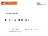
Figure 1 shows the voltage-current characteristic of the<br />
arc expressed by equation (1), for the given values of C<br />
<strong>and</strong> D.<br />
Ua [V]<br />
300<br />
150<br />
0<br />
-150<br />
-300<br />
-120 0 120<br />
Ia [A]<br />
Figure 1. <strong>Arc</strong> furnace voltage-current characteristic<br />
The <strong>in</strong>troduction of the arc length variation, which is<br />
the cause of flicker, is done by the follow<strong>in</strong>g equation:<br />
Va (Ia<br />
) = KVa0<br />
(Ia<br />
)<br />
(2)<br />
where V a0 is the arc voltage correspondent to the reference<br />
length (<strong>in</strong> the present study l 0 = 39.5 cm). Thus, accord<strong>in</strong>g<br />
to equation (1), we have<br />
V<br />
a0<br />
C<br />
(Ia<br />
) = Vat<br />
(l0)<br />
+<br />
(3)<br />
D + I<br />
The threshold voltage V at is given by equation (4)<br />
a<br />
V at (l) = A + Bl<br />
(4)<br />
B. <strong>Arc</strong> length variation<br />
The rapid changes of the arc furnace current dur<strong>in</strong>g the<br />
different stages of the melt<strong>in</strong>g process are highly<br />
correlated with the arc length variation. This variation, <strong>in</strong><br />
turn, depends on the scrap, the gases produced <strong>in</strong> the<br />
process, the electrodynamic forces <strong>and</strong> the position of the<br />
electrodes. Therefore, the accurate representation of the<br />
arc length variation is difficult to achieve. In this attempt,<br />
several authors ([5],[11],[12]) have proposed both<br />
determ<strong>in</strong>istic <strong>and</strong> stochastic laws for the time-doma<strong>in</strong><br />
changes of the arc length.<br />
The determ<strong>in</strong>istic approach is based on a s<strong>in</strong>usoidal<br />
representation of the arc length variation, be<strong>in</strong>g the<br />
frequency chosen <strong>in</strong> the range typical of flicker (0.5 - 25<br />
Hz). When look<strong>in</strong>g for worst-case estimates, a frequency<br />
close to the maximum flicker perceptivity (≅10Hz) can be<br />
chosen.<br />
However, if more realistic calculations are required, the<br />
stochastic model should be used <strong>in</strong>stead. This model,<br />
although more difficult to implement, accounts for the<br />
different frequencies <strong>in</strong>volved <strong>in</strong> the voltage fluctuation<br />
generated by the arc furnaces.<br />
The time variation of the arc length is then given by<br />
l(t)<br />
= l r(t)<br />
(6)<br />
0 −<br />
where l 0 is the reference arc length (l 0 = 39.5 cm) <strong>and</strong> r(t)<br />
is b<strong>and</strong> limited (5 to 20 Hz) white noise signal with an<br />
amplitude vary<strong>in</strong>g up to the maximum arc length deviation<br />
(30.1 cm) from the reference length (39.5 cm).<br />
The time-vary<strong>in</strong>g resistance is easily obta<strong>in</strong>ed by<br />
divid<strong>in</strong>g the evaluated arc voltage V a (t) by the <strong>in</strong>put<br />
current I a (t)<br />
Va<br />
(t)<br />
R(t) = (7)<br />
I (t)<br />
a<br />
This resistance is implemented <strong>in</strong> the ATP by a type 91<br />
time-vary<strong>in</strong>g resistance controlled by MODELS.<br />
Each phase is simulated separately <strong>in</strong> order to predict<br />
unbalances <strong>and</strong> to allow for an accurate harmonic<br />
evaluation.<br />
where A represents a constant that accounts for the arc<br />
anode <strong>and</strong> cathode voltage drops (A = 40 V) <strong>and</strong> B is the<br />
per unit length voltage across the arc (B = 10 V/cm).<br />
The parameter K can then be evaluated by the ratio<br />
between the threshold voltage related to the actual arc<br />
length V at (l) <strong>and</strong> the threshold voltage of the reference arc<br />
length V at (l 0 ).<br />
K<br />
V<br />
(l)<br />
A + Bl<br />
at<br />
= =<br />
(5)<br />
Vat<br />
(l0<br />
) A + Bl0<br />
III. NETWORK DIGITAL SIMULATION<br />
The arc furnace power system represented <strong>in</strong> Figure 2<br />
is implemented <strong>in</strong> the ATP version of the EMTP.<br />
This network represents a typical system where the<br />
Po<strong>in</strong>t of Common Coupl<strong>in</strong>g (PCC) is def<strong>in</strong>ed at the<br />
send<strong>in</strong>g end of the transmission l<strong>in</strong>e (Bus 2) <strong>and</strong> the <strong>Arc</strong><br />
<strong>Furnace</strong> term<strong>in</strong>als are represented by Bus 7.