Low-Power 6-bit 1-GS/s Two-Channel Pipeline ADC with Open ...
Low-Power 6-bit 1-GS/s Two-Channel Pipeline ADC with Open ...
Low-Power 6-bit 1-GS/s Two-Channel Pipeline ADC with Open ...

You also want an ePaper? Increase the reach of your titles
YUMPU automatically turns print PDFs into web optimized ePapers that Google loves.
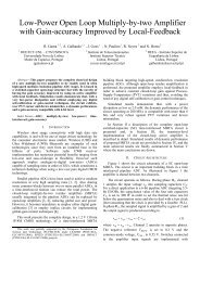
Basically, the fully-differential structure of each pipeline<br />
<strong>ADC</strong> comprises a passive front-end sample-and-hold (S/H),<br />
followed by a cascade of four 1.5-<strong>bit</strong> stages and by a 2-<strong>bit</strong><br />
flash quantizer at the end of the signal path. Each 1.5-<strong>bit</strong><br />
stage comprises a 1.5-<strong>bit</strong> MDAC and a 1.5-<strong>bit</strong> quantizer. The<br />
10 output <strong>bit</strong>s provided by the 5 quantizers are then digitally<br />
synchronized and a net resolution (N) of 6 <strong>bit</strong>s is available at<br />
the output after applying synchronization and standard<br />
digital correction (summing all five 2-<strong>bit</strong> words <strong>with</strong> 1-<strong>bit</strong><br />
overlap). Each 1.5-<strong>bit</strong> MDAC block operates at 500 MS/s in<br />
order to relax the speed requirements of the amplifiers by a<br />
factor of 2. Since MDACs of the same stage, but of different<br />
channel, operate in opposite phases, they are able to share the<br />
same amplifier. Four equal sized amplifiers are, therefore,<br />
shared between channels, namely A1 to A4.<br />
The 1.5-b quantizers FQ11 and FQ12, adjacent to the<br />
lower pipeline perform quantizations at 500 MHz. The other<br />
four 1.5-b quantizers namely, FQ2, FQ3, FQ4 and FQ5,<br />
operate at 1 GHz, since they are also shared between stages<br />
in order to reduce area. Finally, at the output, a digital<br />
multiplexer operating at full speed is used in order to provide<br />
the 6-<strong>bit</strong> digital output at a 1 <strong>GS</strong>/s clock rate.<br />
S/H1<br />
φ 1n<br />
S/H2<br />
φ 1<br />
MDAC<br />
11<br />
MDAC<br />
12<br />
FQ11<br />
φ F1n<br />
S(1)<br />
S(1)<br />
H(1)<br />
S(2)<br />
S(1)<br />
H(1)<br />
S(3)<br />
H(2)<br />
RA(1)<br />
S(2)<br />
S(3)<br />
H(3)<br />
S(4)<br />
S(3)<br />
RA(2)<br />
H(3)<br />
S(5)<br />
H(4)<br />
RA(3)<br />
S(4)<br />
S(5)<br />
H(5)<br />
S(6)<br />
S(5)<br />
RA(4)<br />
H(5)<br />
S(7)<br />
H(6)<br />
RA(5)<br />
S(6)<br />
S(7)<br />
H(7)<br />
S(8)<br />
S(7)<br />
RA(6)<br />
H(7)<br />
S(9)<br />
H(8)<br />
RA(7)<br />
S(8)<br />
S(9)<br />
H(9)<br />
S(10)<br />
S(9)<br />
RA(8)<br />
H(9)<br />
S(11)<br />
H(10)<br />
RA(9)<br />
S(10)<br />
S(11)<br />
H(11)<br />
S(12)<br />
S(11)<br />
RA(10)<br />
All clock-phase signals are obtained from a 1 GHz<br />
master clock, clk, as depicted in Fig. 3. No non-overlapping<br />
clock-phase generators are used. The first D Flip-Flop (D-<br />
FF) is used to lower the frequency and obtain the 500 MHz,<br />
φ 1 and φ 1n, complementary phases. Using φ 1 and φ 1n, and<br />
the master clock the 90º phase-shift phases, φ F and φ Fn, to<br />
drive quantizers FQ2 to FQ5 are generated. Thought a<br />
second D-FF, phases φ F1 and φ F1n are produced to drive<br />
quantizers FQ12 and FQ11, respectively. Finally, auxiliary<br />
phase φ aux is generated as shown in Fig. 3 using a simple OR<br />
gate. All phases are properly buffered using digital buffers<br />
<strong>with</strong> the driving capability sized according to the load.<br />
clk<br />
φ 1<br />
φ F<br />
III.<br />
D Q<br />
D-FF _<br />
clk Q<br />
D Q<br />
D-FF _<br />
clk Q<br />
φ F1<br />
φ F1n<br />
φ 1<br />
φ 1n<br />
φ F<br />
clk<br />
Figure 3. Clock signals generation.<br />
φ Fn<br />
φ F<br />
φ aux<br />
DESIGN OF THE BASIC BUILDING-BLOCKS<br />
A. The 1.5-<strong>bit</strong> MDAC<br />
Instead of using a closed-loop amplifier <strong>with</strong> high gain,<br />
as usually employed in the conventional schemes, it is used<br />
an open-loop amplifier in the MDAC stages [3, 4].<br />
V REFN<br />
/2<br />
V REFP<br />
/2<br />
V CM<br />
X<br />
Y<br />
Z<br />
FQ12<br />
φ F1<br />
MDAC<br />
21<br />
MDAC<br />
22<br />
FQ2<br />
φ Fn<br />
S(2) H(2) S(4) H(4) S(6) H(6) S(8) H(8) S(10) H(10)<br />
S(1) Q(1) S(3) Q(3) S(5) Q(5) S(7) Q(7) S(9) Q(9)<br />
S(2) Q(2) S(4) Q(4) S(6) Q(6) S(8) Q(8) S(10)<br />
φ 1<br />
φ 1n<br />
V REFN<br />
1<br />
v ip<br />
φ<br />
C Sp 1n φ1 in p<br />
+ +<br />
AMP<br />
φ<br />
v op<br />
vin<br />
φ 1n<br />
in n<br />
G=2<br />
_ _<br />
v on<br />
φ 1<br />
φ<br />
C 1n<br />
Sn<br />
V REFP<br />
/2 X V REFN<br />
V REFN<br />
/2 Y<br />
Z<br />
V CM<br />
φ aux<br />
Figure 2. Control clock signals and architecture timing.<br />
The control and timing signals are shown in Fig. 2. The<br />
single-phase technique described in [6] is used and, hence,<br />
only one clock phase is used, φ 1 , and it complementary<br />
version, φ 1n . These complementary phases are used to drive<br />
the two S/H blocks and all 1.5-<strong>bit</strong> MDACs. Front-end<br />
quantizers FQ11 and FQ12 (operating at 500 MHz) are<br />
controlled by clock signals φ F1 and φ F1n and, the remaining<br />
quantizers (operating at 1 GHz) are driven by phases φ F and<br />
φ Fn . In order to let the amplifiers to settle in a complete 2 ns<br />
time-slot, the quantization of all 1.5-<strong>bit</strong> flash <strong>ADC</strong>s is done<br />
in the middle of the sampling-phase of the 1.5-<strong>bit</strong> MDACs of<br />
the same stage. Finally, an auxiliary clock signal φ aux, used<br />
to cancel the time-skew errors between the two channels, is<br />
also displayed.<br />
Figure 4. Fully-differential implementation of the 1.5-<strong>bit</strong> MDAC based<br />
on open-loop amplification.<br />
As illustrated in Fig. 4, the input voltage, v ip , is sampled<br />
into C Sp (nominally set to 0.3 pF due to KT/C noise<br />
constraints) during phase φ 1n. During φ 1, the sampled signal<br />
is amplified by a gain of 2, and the output amplified residue<br />
is produced according to<br />
⎛ VREFD<br />
VREFD<br />
⎞<br />
v = v − v = −2⎜v<br />
+ X − Y + Z ⋅ 0⎟<br />
(1)<br />
od op on<br />
id<br />
⎝ 2 2 ⎠<br />
where vid<br />
= vip<br />
− vin<br />
, VREFD<br />
= VREFP<br />
−VREFN<br />
, and the<br />
digital signals X, Y and Z are provided by the local 1.5-<strong>bit</strong><br />
quantizer and only one is active at a time. The residue<br />
amplification gain, G, needs to be made accurately equal to 2<br />
(<strong>with</strong> an error smaller than ±1.56 % for 6-<strong>bit</strong> accuracy). The