Instruction Manual - Dover Flexo Electronics, Inc
Instruction Manual - Dover Flexo Electronics, Inc
Instruction Manual - Dover Flexo Electronics, Inc

You also want an ePaper? Increase the reach of your titles
YUMPU automatically turns print PDFs into web optimized ePapers that Google loves.
DOVER FLEXO ELECTRONICS, INC.<br />
ISO 9001 CERTIFIED<br />
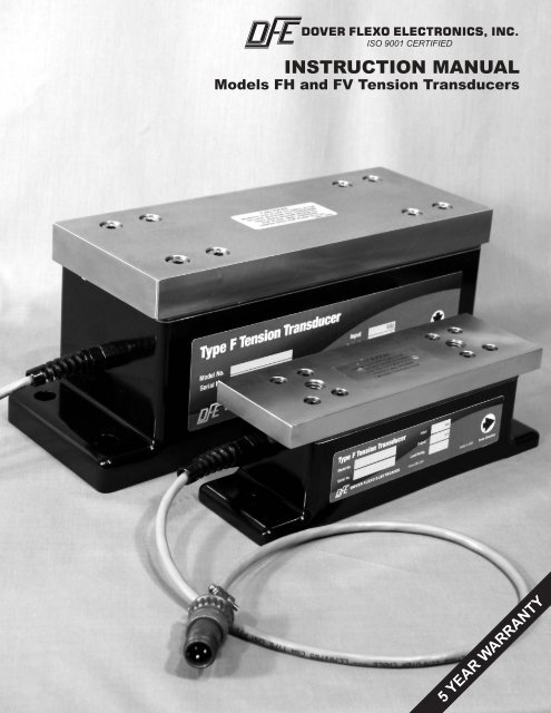
INSTRUCTION MANUAL<br />
Models FH and FV Tension Transducers<br />
5 YEAR WARRANTY
217 Pickering Road<br />
Rochester, NH 03867-4630 U.S.A.<br />
For assistance, please call:<br />
TECHNICAL SERVICE - Installations, Start-Up, Troubleshooting, Repairs, Field<br />
Service, Returns. techsupport@dfe.com<br />
CUSTOMER SERVICE - Replacement Parts, Individual Products, Questions about<br />
Orders, <strong>Manual</strong>s. customerservice@dfe.com<br />
SALES - Product Information, Systems Application Questions, and<br />
placing orders for standard products and special systems.<br />
sales@dfe.com<br />
Telephone: (603) 332-6150 Fax: (603) 332-3758<br />
E-mail: info@dfe.com Internet: www.dfe.com<br />
©2010 <strong>Dover</strong> <strong>Flexo</strong> <strong>Electronics</strong>, <strong>Inc</strong>. All rights reserved. <strong>Dover</strong> <strong>Flexo</strong> <strong>Electronics</strong> has made reasonable effort to ensure accuracy of this<br />
document. However NO WARRANTY, whether expressed or implied, is given regarding the completeness or correctness of information in<br />
this document. <strong>Dover</strong> <strong>Flexo</strong> <strong>Electronics</strong> shall not be liable for damages of any kind arising from the use or misuse of this document. <strong>Dover</strong><br />
<strong>Flexo</strong> <strong>Electronics</strong> reserves the right to make changes, additions, and deletions to this document without notice and without obligation.
TABLE OF CONTENTS<br />
SECTION ONE: DESCRIPTION AND OPERATION PAGE<br />
1.1 General Description ................................... 1<br />
1.2 Mechanical Operation .................................. 1<br />
1.3 Electrical Operation ................................... 2<br />
1.4 Specifications ........................................ 3<br />
1.5 Standard Features .................................... 3<br />
1.6 Options ............................................. 3<br />
SECTION TWO: INSTALLATION<br />
2.1 Dimensions.......................................... 4<br />
2.2 Pre-installation Requirements ........................... 5<br />
2.3 Installing the Transducers .............................. 6<br />
SECTION THREE: CALIBRATION AND SETUP<br />
3.1 Introduction .................................... 9<br />
3.2 Connection to the <strong>Electronics</strong> ...................... 9<br />
3.3 Zero the Tension Meter ........................... 9<br />
3.4 Calibrate the Tension Meter........................ 9<br />
SECTION FOUR: CARE AND MAINTENANCE<br />
4.1 Removal of Roll and Pillow Blocks ........................ 10<br />
4.2 Removing Transducers ................................ 10<br />
SECTION FIVE: TROUBLESHOOTING GUIDE ........................ 11<br />
SECTION SIX: REPLACEMENT PARTS ............................. 13<br />
Appendices: A. Transducer Electrical Connections ..................... 14<br />
B. Selection of Load Rating ............................. 15<br />
C. Typical Tensions ................................... 17<br />
Terms and Conditions of Sale ........................... 18<br />
Index ............................................... 19<br />
FIGURES<br />
1. FH Transducer Operation............................... 1<br />
2. FV Transducer Operation ............................... 2<br />
3. Strain Gage Connections ............................... 2<br />
4. Dimensions.......................................... 4<br />
5. Tension Zones ....................................... 5<br />
6. Minimum Shaft Length ................................. 6<br />
7. FH Transducer Orientation .............................. 6<br />
8. FV Transducer Orientation .............................. 7<br />
9. Bearing Mounting Bolt Length ........................... 8<br />
10. Web Path ........................................... 9<br />
11. Model F Transducer Wiring ............................. 14<br />
-i-
-ii-
SECTION 1<br />
PRODUCT DESCRIPTION<br />
1.1 GENERAL DESCRIPTION<br />
The model F transducer is a heavy-duty flat transducer, designed to be used in pairs, to accurately measure<br />
web tension in machines having live (rotating) shaft idler rolls. The shaft rides in standard, industrial pillow<br />
block bearings mounted on each end. The bearings are then bolted to the transducer top plates. Typically used<br />
for high tension and/or high speed applications.<br />
An F transducer consists of a single-piece aluminum base with a removable stainless steel top plate. A seal<br />
between the base and top plate prevents intrusion by dust, water, or other contamination. The transducer’s<br />
electrical connector is located at the end of a short cable for easy access during installation. Each transducer<br />
contains two high-output semiconductor strain gauges connected in a half Wheatstone Bridge configuration.<br />
When two transducers are connected together, a full bridge is formed.<br />
The model F transducer is available in a V (vertical) configuration or an H (horizontal) configuration. The V<br />
is used when the tension force is roughly perpendicular to the top plate of the transducer. The H configuration<br />
is used when the tension force is mostly parallel to the transducer top plate. The V and H configurations have<br />
identical outside dimensions, within each frame size. Two frame sizes are available; size 2 and size 3.<br />
1.2 MECHANICAL OPERATION<br />
1. The FH (Horizontal) Tension Transducer.<br />
The FH Transducer can be installed in any position. But, when installed horizontally, the idler roll weight<br />
does not affect the output thereby increasing the effective range of the transducer.<br />
Inside the transducer is a pair of cantilever beams having strain gages. The top plate is attached to the<br />
beams, and when moved in a direction parallel to the base, the beams bend a small amount creating an<br />
electrical output from the strain gauges. If the tension force is in the opposite direction from the arrow on the<br />
label, the electrical output will have reverse polarity.<br />
Mechanical stops prevent damage from overloads. The stops are functional in both horizontal directions.<br />
Figure 1 - FH TRANSDUCER OPERATION<br />
1
2. The FV (Vertical) Tension Transducer.<br />
The FV Transducer can be installed in any position.<br />
The FV has a single beam with strain gages, and a hinge. Tension force from the top plate causes the<br />
beam to bend a small amount, allowing the top plate to pivot on the hinge at the connector end.<br />
Mechanical stops prevent damage from overloads. The stops are functional in both vertical directions.<br />
Bending the beam a small amount creates an electrical output from the strain gauges. If the tension force<br />
is in the opposite direction from the arrow on the label, the output will have reverse polarity.<br />
Figure 2 - FV TRANSDUCER OPERATION<br />
1.3 ELECTRICAL OPERATION (see Figure 3)<br />
The Model F Transducer is used in pairs, one on each end of an idler roll shaft. Web tension exerts a force on<br />
the roll which is transmitted to the beam by the top plate. Two semiconductor strain gauges are mounted on the<br />
beam. As force is applied and the beam deflects, one gauge is stretched and the other gauge is compressed.<br />
This increases the electrical resistance of the stretched gauge and decreases the resistance of the compressed<br />
gauge. The gauges in both transducers are electrically connected together in a Wheatstone bridge configuration.<br />
The bridge produces double the output of a single transducer and averages the outputs so web position, width<br />
and loose or tight edges do not affect the accuracy of the tension signal.<br />
Figure 3 - STRAIN GAUGE CONNECTIONS<br />
2
The physical location of the strain gauges, on opposite sides of the beam, ensures that each gauge experiences<br />
the same temperature variations. This, and the Wheatstone bridge configuration, provides automatic<br />
temperature compensation and a stable output.<br />
The strain gauges are high output semiconductor devices which typically have an output sixteen times greater<br />
than the inexpensive foil gauges used in some transducers. Therefore, the signal amplifier used with these<br />
Model F transducers is a very stable low-gain design. An added benefit of the high output is inherent immunity<br />
to electrical noise. And semiconductor strain gauges have a very long life span.<br />
1.4 SPECIFICATIONS<br />
Electrical Specifications:<br />
Excitation Voltage ............. 5 Volts dc (10V with XR option)<br />
Full Scale Output ............. 250 mVdc nominal (500mVdc with XR)<br />
Strain Gage Resistance ............. 100 ohms nominal (200 ohms, XR)<br />
Non-Repeatability ............. ± 1/4% full span (FS)<br />
Non-Linearity and Hysteresis Combined ......... ± 1/2% FS<br />
Temperature Range ............. -10°F to +200°F (-23°C to 93°C)<br />
Electrical Connections ............. pin A....white wire..output<br />
............. pin B....black wire....... +/- 5V<br />
............. pin C....red wire.......... - /+ 5V<br />
Mating Electrical Connector ............. Amphenol MS3106A-10SL-3S<br />
Mechanical Specifications:<br />
Materials ............. 303/304 stainless steel and aluminum<br />
Load Ratings: Size 2 ............. 50 (V only), 100, 200, 400, 800, 1200 lbs.<br />
(225, 450, 900, 1800, 3600, 5350 N)<br />
Size 3 ............. 1000, 2500, 5000 lbs. (4450, 11125, 22250 N)<br />
Static Overload Capacity: ............. 5 times load rating, minimum<br />
Load Direction:<br />
H - horizontal ............. parallel to top plate ± 30°, away from cable end<br />
V - vertical ............. + /- 30° perpendicular to top plate, toward top plate<br />
Weight: Size 2: ............. 7 lbs. (3 Kg)<br />
Size 3: ............. 42 lbs. (19 Kg.)<br />
1.5 STANDARD FEATURES<br />
• Corrosion-resistant stainless steel and aluminum construction<br />
• Sealed against dust and water<br />
• Zero maintenance design; no wear- parts<br />
• Attached cable with Amphenol connector, instead of connector mounted on device.<br />
• Tethered top plate prevents separation from transducer in the unlikely event of beam failure.<br />
1.6 OPTIONS<br />
• Drilled and Tapped top plate (D&T). Top plate drilled and tapped for bearing.<br />
• Extended Range output (XR) - Produces twice the output signal for a given load rating. Must be used with<br />
electronics having extended range option.<br />
• Oversized Top Plate (OTP) - For mounting of oversized pillow block bearing.<br />
• Permanently Attached Cable (PT). Permanently attached cable with tinned leads instead of Amphenol<br />
connector.<br />
3
SECTION 2<br />
INSTALLATION<br />
2.1 DIMENSIONS<br />
Figure 4 - DIMENSIONS<br />
4
2.2 PRE-INSTALLATION REQUIREMENTS<br />
A. TRANSDUCER ROLL<br />
The Model F Transducers are used in pairs. One is mounted on each end of an idler roll shaft. The roll<br />
chosen is called the Transducer Roll.<br />
1. THE TRANSDUCER ROLL MUST BE A TRUE IDLER! It can NOT be a driven roll! There can be NO<br />
brakes, clutches, belts, chains or gears attached to it or its shaft. It can not be a nip roll or be in contact<br />
with a nip roll. It can not be filled with water or have pipes or hoses attached to it. NOTHING MUST<br />
CONTACT THE ROLL OR ITS SHAFT EXCEPT THE WEB!<br />
2. The Transducer Roll shaft is live (rotating). It must be designed and built for rotating service. Usually<br />
this means that it is straight, dynamically balanced and strong enough to resist bending from web tension<br />
forces.<br />
3. The roll must be DYNAMICALLY BALANCED if web speed is over 300 FPM! Refer to Section 2.3.3:<br />
BALANCE THE ROLL for specifications. An unbalanced roll will reduce the accuracy of the tension<br />
signal.<br />
B. TENSION ZONE<br />
The roll must be located in the tension zone which is to be monitored or controlled. The beginning or end of<br />
any tension zone is always at a nip (driven or braked), unwind shaft, rewind shaft or drag bar. Any element<br />
in the web path that can change web tension is at one end of a tension zone.<br />
C. WRAP ANGLE<br />
Figure 5 - TENSION ZONES<br />
The web must always contact the transducer roll in exactly the same way. The wrap angle must not change<br />
as the unwind or rewind roll diameter changes. Therefore there must be at least one idler roll between the<br />
transducer roll and the unwind or rewind shaft. If the machine has more than one webbing path, be sure to<br />
choose a roll that is wrapped the same for each. Otherwise it will be necessary to install an additional pair of<br />
transducers, or dual calibration circuitry, or both. If the wrap angle is allowed to change, the transducer<br />
output will change with angle as well as tension, and accuracy will be reduced. The transducer roll must be<br />
wrapped such that the resultant tension force is mostly parallel to the top plate of the FH transducer and<br />
mostly perpendicular to the top plate of the FV transducer.<br />
D. MOUNTING SURFACE<br />
The structure on which the transducers are mounted MUST be very stable and strong. Any movement of the<br />
structure may be sensed by the transducers and may cause inaccurate tension readings. The surfaces must<br />
also be smooth and flat so the transducers won't be uneven when they are installed.<br />
5
2.3 INSTALLING THE TRANSDUCERS<br />
Model F Transducers are very easy to install. Normally, both transducers are mounted on the machine and the<br />
roll is then installed on them. Follow the simple steps below.<br />
1. DETERMINE SHAFT LENGTH<br />
Measure the center to center distance between the transducer bases. Call this D T . W is the width of one<br />
pillow block bearing. Use the following formula to determine the minimum shaft length:<br />
For both FV and FH transducers: MINIMUM SHAFT LENGTH = D T + W<br />
Figure 6 - MINIMUM SHAFT LENGTH<br />
2. MOUNT THE TRANSDUCERS ON THE MACHINE<br />
To Mount FH Transducers:<br />
Mount the transducers on the machine making sure that the transducers are facing in the direction of the<br />
tension force (See Figure 7) and the cables point in the same direction. The tension force arrow on the<br />
transducers denotes the proper direction for the transducers. The load force direction acts parallel to the top<br />
plate and should not exceed an angle of 30° with the top plate. Larger angles may result in unsatisfactory<br />
performance. To review load rating sizing formulas, see Appendix B.<br />
Figure 7 - FH TRANSDUCER ORIENTATION<br />
6
To Mount FV Transducers:<br />
The FV transducer is designed to measure forces which are mostly perpendicular to the top plate (See figure<br />
8). Mount the transducers on the machine making sure that the transducer force direction and mounting<br />
surface is the same as that used when the transducer load rating was sized for this application, and that the<br />
cable end of both transducers are on the same side of the roll. To review load rating sizing formulas, see<br />
Appendix B.<br />
NOTE: To get expected results, be sure the installers are given the details of mounting orientation,<br />
connector end, and tension force direction. Application sketches are helpful.<br />
Figure 8 - FV TRANSDUCER ORIENTATION<br />
3. BALANCE THE ROLL<br />
The roll must be dynamically balanced if web speed is 300 FPM or more. Balance the roll to Quality Grade<br />
G-2.5 as described in ISO 1940 and ANSI S2.19-75 standards. If these standards are not available, please<br />
contact DOVER FLEXO ELECTRONICS and we will provide the appropriate data.<br />
4. SELECTION OF PILLOW BLOCK BEARING<br />
The bearing must have self-aligning capability. The self-aligning feature will avoid unnecessary stress on<br />
the transducers caused by misalignment during installation and by roll deflection. One bearing must be<br />
installed so the shaft can move axially a small amount (float).The floating feature will avoid forces caused by<br />
temperature variations of the shaft. These factors could cause inaccurate output or damage the transducers.<br />
A 100° F temperature change causes approximately 0.077" change in length of a 10 ft. long piece of steel.<br />
The other bearing should not allow the shaft to float axially.<br />
5. REMOVE THE TOP PLATE TO DRILL FOR THE PILLOW BLOCK BEARING<br />
1. Remove the eight screws holding the top plate to the transducer. Be careful not to lose the “O” rings<br />
installed in the sealing plate. These are seals that keep out water. Do not remove the red sealing plate<br />
under the top plate.<br />
2. Remove the top plate and drill and tap the holes for the pillow block bearing being used.<br />
3. Replace the top plate and secure with the eight screws. Tighten the screws as follows: Size 2 to 7 FT-<br />
LBS of torque, Size 3 to 29 FT-LBS of torque.<br />
6. INSTALL THE ROLL AND BEARINGS ON THE TRANSDUCERS<br />
1. Place the bearings loosely on the roll shaft.<br />
2. Place the bearings and roll on the transducers and mount the bearings to the transducers with the<br />
appropriate cap screws. The length of the cap screws should be sufficient to anchor the bearings, but not<br />
so long as to exceed the maximum thread engagement with the top plate (0.54" for the size F2, 0.92" for<br />
Size F3). If the cap screw is too long, the bearing will not clamp tightly to the top plate and the screw<br />
will interfere with force transfer to the sensing beam, and vibration and damage can occur. See Figure 9.<br />
CAUTION! Do not use a bolt which is too long!<br />
7
Figure 9 - BEARING MOUNTING BOLT LENGTH<br />
3. Fasten the shaft in the bearings at this time. Be sure the floating bearing is installed with the axial gap on<br />
the side of the bearing facing the roll end so the shaft can grow in length as it gets hot, without causing<br />
stress on the bearing.<br />
8
SECTION 3<br />
CALIBRATION AND SETUP<br />
3.1 INTRODUCTION<br />
There are no calibration adjustments on the Model F Transducer itself. The instructions below are for the<br />
electronics device which the transducers are connected to. All of the following terminology and procedures,<br />
assume that the transducers are connected to a DOVER FLEXO ELECTRONICS tension controller or tension<br />
indicator. If some other electronics are being used, you should follow the instructions furnished with it.<br />
If your DFE electronic indicator or controller is equipped with Quik-Cal, then disregard these instructions<br />
and follow the instructions that came with the indicator or controller.<br />
These are general instructions which are correct for most DFE controllers and indicators, and are placed here<br />
for your convenience. If you have any difficulty calibrating or if there is any discrepancy between these<br />
instructions and those in the <strong>Instruction</strong> <strong>Manual</strong> for the indicator or controller, you should disregard these<br />
instructions and follow the instructions in the <strong>Manual</strong> for the indicator or controller.<br />
The transducers must be properly installed and oriented as directed in SECTION 2.3.<br />
3.2 CONNECTION TO THE ELECTRONICS<br />
Verify that the transducers are installed according to the instructions in sections 2.2 and 2.3 of this manual.<br />
Plug the transducer cords into the cables from the electronics device. Refer to Appendix A for connections if the<br />
device cables do not have connectors on the device end.<br />
3.3 ZERO THE TENSION METER<br />
1. Turn the "POWER" switch off. If the meter does not read zero, turn the mechanical adjustment screw on the<br />
meter face so the needle indicates zero tension.<br />
2. Find an object that weighs at least 25% of the maximum value on the tension meter scale. (Be sure you<br />
know the exact weight).<br />
3. Find a rope, tape, or wire that will support the weight in 2. above.<br />
4. Verify that there is no web contacting the Transducer Roll. Turn the "POWER" switch on. Wait a few<br />
seconds for the tension meter to settle. Turn the "CALIBRATE" pot. to approximately 75%. Then, turn the<br />
"ZERO" pot. so the tension meter reads zero tension.<br />
3.4 CALIBRATE THE TENSION METER<br />
See Figure 10. Pass the rope over the Transducer Roll in exactly the same path as the web follows. Tie the<br />
end in the machine at least one idler roll beyond the Transducer Roll. Pass the other end by at least one idler<br />
roll before the Transducer Roll. Be sure the rope does not pass over any driven rolls, braked rolls or dead bars.<br />
(This will cause inaccurate calibration). Attach the weight to the free end of the rope and let it hang without<br />
touching anything. Turn the "CALIBRATE" pot. so the tension meter reads the same as the weight. Remove<br />
the weight and rope. This concludes the calibration procedure. Rope follows web path exactly. All rolls must be<br />
free-turning idlers.<br />
Figure 10 - WEB PATH<br />
9
SECTION 4<br />
CARE AND MAINTENANCE<br />
Your <strong>Dover</strong> <strong>Flexo</strong> <strong>Electronics</strong> Model F Tension Transducers have been designed and manufactured to require<br />
no periodic maintenance. With proper application and installation your transducers will be maintenance-free<br />
and long-lasting. Any changes in your application which affect the dynamics of your equipment such as web<br />
speed, tension force, material, etc. could possibly require upgrading of load rating or a roll change. Contact<br />
<strong>Dover</strong> for specific information and engineering advice.<br />
4.1 PROCEDURE FOR REMOVING ROLL AND PILLOW BLOCKS<br />
To remove the transducers follow the procedure below to remove the roll and bearings from the transducers.<br />
1. Support the idler roll so it won't fall.<br />
2. Remove the bolts from the bearings on each transducer.<br />
3. Take the roll and bearings off of the transducers.<br />
4.2 PROCEDURE FOR REMOVING TRANSDUCERS<br />
1. Disconnect the electrical cable on each transducer.<br />
2. Remove the screws mounting the transducer and repeat for the opposite side.<br />
10
SECTION 5<br />
TROUBLESHOOTING GUIDE<br />
This is a list of problems which could occur during initial start-up or afterwards. The probable causes are listed<br />
with the most likely one first and the least likely one last.<br />
1. TRANSDUCER ROLL SHAKES, VIBRATES or BOUNCES<br />
a. Roll is not balanced. See Section 2.3.3 and Section 2.2.A.3.<br />
b. Shaft is not clamped tightly in bearings. Mounting screws are loose or shaft diameter is undersized.<br />
c. Transducer mounting bolts are not tight.<br />
d. Shaft is too weak or there is too much shaft extension between the roll ends and the transducers.<br />
e. Shaft is bent or too weak. (This refers to live shaft idler rolls, only)<br />
f. Roll is turning at its natural frequency. Call DFE for analysis of conditions and solution to problem.<br />
2. CAN NOT ADJUST TENSION METER TO READ ZERO WHEN WEB IS SLACK<br />
a. Transducer roll is too heavy. See Appendix B for sizing formulas.<br />
b. Transducers are pre-loaded. See Sections 2.3.1 and 2.3.4.<br />
3. TENSION METER READS BACKWARDS<br />
a. Transducers are installed backwards with force arrow pointing in opposite direction. See Section 2.3.2.<br />
b. Transducer cables are connected wrong at controller/indicator terminal strip. Signal wires are reversed.<br />
4. TENSION METER NEEDLE PEGS HIGH OR LOW<br />
a. Meter is not electrically adjusted to zero. See Section 3.3, page 9.<br />
b. Transducers are pre-loaded. See Sections 2.3.1 and 2.3.4.<br />
c. Transducer cable has broken wire, poor connection or short circuit.<br />
d. A strain gage has failed. To verify: Unplug the transducer cable and use an ohm-meter to measure the<br />
resistance of the gages at the connector on the transducer. Measure between pins A,B, and A,C. In each<br />
case, the resistance should be about 100 ohms. Measure the resistance between any pin and the outside<br />
of the transducer. The meter should read infinite resistance. Apply a force to the roll by hand or by<br />
using a rope and a weight, in the direction of the tension force and maintain it while again measuring<br />
between pins A,B and A,C. The resistance should be only a few ohms different from before.<br />
e. Failure in the tension amplifier circuit of the controller/indicator.<br />
5. TENSION METER DOES NOT READ ZERO WHEN WEB IS SLACK AND READING DRIFTS WITH TIME.<br />
a. Transducers are pre-loaded. See Sections 2.3.1 and 2.3.4.<br />
b. The structure the transducers are mounted on is weak. See Section 2.2.D.<br />
c. Transducer cable has a broken wire, poor connection or short circuit.<br />
d. A strain gage is cracked. Perform the test in 4d above.<br />
6. TENSION METER DOES NOT READ THE SAME EACH TIME THE SAME FORCE IS APPLIED (poor<br />
repeatability)<br />
a. Transducers are pre-loaded. See Sections 2.3.1 and 2.3.4.<br />
b. The structure the transducers are mounted on is weak. See Section 2.2.D.<br />
c. The bearing or transducer mounting screws are loose.<br />
11
7. TENSION METER READING DOES NOT CHANGE WHEN FORCE IS APPLIED TO ROLL. METER<br />
READS ZERO.<br />
a. Force direction arrow on one transducer is backwards. See Section 2.3.2.<br />
b. Transducer roll is too heavy. See Appendix B, page 15.<br />
c. Transducer cable has broken wire, poor connection or short circuit.<br />
d. Transducer cables connected incorrectly, or to wrong transducers.<br />
e. Failure of tension amplifier circuit in controller/indicator. Unit not turned on.<br />
8. TENSION METER NEEDLE BOUNCES<br />
a. Web tension is fluctuating because of machine speed fluctuations, bent roll shafts, worn idler roll<br />
bearings, chattering unwind brake, flat spot in unwind or rewind roll, etc.<br />
b. Shaft is loose in the bearings. Bearing mounting screws are loose or shaft diameter is under-size.<br />
c. Transducer mounting bolts are loose.<br />
d. Tension controller is not adjusted properly. See controller <strong>Instruction</strong> <strong>Manual</strong> for procedure.<br />
12
SECTION 6<br />
REPLACEMENT PARTS<br />
6.1 REPLACEMENT PARTS FOR THE F TRANSDUCER<br />
PART F2H F2V F3H F3V<br />
Top Plate 203-2692 203-2692 203-2808 203-2808<br />
Top Plate Screws 123-0278 M5 x 16 Socket Head Cap 123-0065 M8 x 30 Socket Head Cap<br />
Cable<br />
Not Replaceable - Factory Repair<br />
<strong>Instruction</strong> <strong>Manual</strong>: Doc 801-2224<br />
Call Customer Service for prices and for part numbers of items not listed. For help with service or repairs, call<br />
Technical Service. We can be reached by the following:<br />
Phone: 603-332-6150<br />
Fax: 603-332-3758<br />
E-mail: Customer Service: customerservice@dfe.com<br />
Technical Service: techsupport@dfe.com<br />
13
Appendix A:<br />
Transducer Electrical Connections<br />
Figure 11 - MODEL F TRANSDUCER WIRING<br />
14
Appendix B:<br />
Selection of Load Rating<br />
SELECTION OF LOAD RATING FOR FH TRANSDUCERS<br />
15
SELECTION OF LOAD RATING FOR FV TRANSDUCERS<br />
16
Appendix C:<br />
Typical Tensions for Various Materials<br />
TYPICAL TENSIONS FOR WEB MATERIALS<br />
ACETATE<br />
0.5 lb. per mil per inch of width<br />
FOIL Aluminum 0.5 lb. per mil per inch of width<br />
Copper 0.5 lb. "<br />
CELLOPHANE<br />
0.75 lb. per mil per inch of width<br />
NYLON<br />
0.25 lb. per mil per inch of width<br />
PAPER 15 lb * 0.4 lb. per inch of width<br />
20 lb 0.5 lb. "<br />
30 lb 0.75 lb. "<br />
40 lb 1.25 lb. "<br />
60 lb 2.0 lb. "<br />
80 lb 3.0 lb. "<br />
100 lb 4.0 lb. "<br />
* based on 3000 sq. ft. ream<br />
PAPERBOARD 8pt 3.0 lb. per inch of width<br />
12pt 4.0 lb. "<br />
15pt 4.5 lb. "<br />
20pt 5.5 lb. "<br />
25pt 6.5 lb. "<br />
30pt 8.0 lb. "<br />
POLYETHYLENE<br />
0.12 lb. per mil per inch of width<br />
POLYESTER (Mylar)<br />
0.75 lb. per mil per inch of width<br />
POLYPROPYLENE<br />
0.25 lb. per mil per inch of width<br />
POLYSTYRENE<br />
1.0 lb. per mil per inch of width<br />
RUBBER GAUGE AT 25% STRETCH AT 50% STRETCH<br />
10 mil 1.75 3.68<br />
12 mil 1.10 2.03<br />
16.5 mil 4.09 8.17<br />
26 mil 2.47 4.97<br />
SARAN<br />
0.15 lb per mil per inch of width<br />
STEEL GAUGE - INS UNWIND-PSI REWIND-PSI<br />
0.001 - 0.005 1000 4000<br />
0.006 - 0.025 850 3500<br />
0.026 - 0.040 750 3000<br />
0.041 - 0.055 650 2600<br />
0.058 - 0.070 550 2200<br />
0.071 - 0.090 450 1800<br />
0.091 - 0.120 450 1400<br />
0.121 - 0.140 400 1200<br />
0.141 - 0.165 400 1000<br />
0.166 - 0.200 400 900<br />
0.201 - 0.275 400 800<br />
0.276 - 0.380 300 700<br />
VINYL<br />
0.05 lb. per mil per inch of width<br />
*** For laminated webs, sum the tension for the individual webs and add 0.1 lb per inch of width.<br />
17
TERMS AND CONDITIONS OF SALE AND SHIPMENT<br />
1. THE COMPANY<br />
<strong>Dover</strong> <strong>Flexo</strong> <strong>Electronics</strong>, <strong>Inc</strong>. is hereinafter referred to as the<br />
Company.<br />
2. CONFLICTING OR MODIFYING TERMS<br />
No modification of, additions to or conflicting provisions to these<br />
terms and conditions of sale and shipment, whether oral or written,<br />
incorporated into Buyer's order or other communications are<br />
binding upon the Company unless specifically agreed to by the<br />
Company in writing and signed by an officer of the Company.<br />
Failure of the Company to object to such additions, conflicts or<br />
modifications shall not be construed as a waiver of these terms<br />
and conditions nor an acceptance of any such provisions.<br />
3. GOVERNING LAW<br />
This contract shall be governed by and construed according to<br />
the laws of the state of New Hampshire, U.S.A. The parties agree<br />
that any and all legal proceedings pursuant to this contract shall<br />
take place under the jurisdiction of the courts of the State of New<br />
Hampshire in the judicial district of Strafford County.<br />
4. PENALTY CLAUSES<br />
Penalty clauses of any kind contained in orders, agreements or<br />
any other type of communication are not binding on the Company<br />
unless agreed to by an officer of the Company in writing.<br />
5. WARRANTY<br />
<strong>Dover</strong> <strong>Flexo</strong> <strong>Electronics</strong>,<strong>Inc</strong>. warrants, to the original Buyer, its'<br />
products to be free of defects in material and workmanship for five<br />
years from date of original shipment. Repairs on products are<br />
warranted for 90 days from date of shipment. During the warranty<br />
period the Company will repair or replace defective products free<br />
of charge if such products are returned with all shipping charges<br />
prepaid and if, upon examination, the product is shown to be<br />
defective. This warranty shall not apply to products damaged by<br />
abuse, neglect, accident, modification, alteration or mis-use.<br />
Normal wear is not warranteed. All repairs and replacements<br />
under the provisions of this warranty shall be made at <strong>Dover</strong><br />
<strong>Flexo</strong> <strong>Electronics</strong> or at an authorized repair facility. The Company<br />
shall not be liable for expenses incurred to repair or replace<br />
defective products at any other location or by unauthorized persons<br />
or agents. This warranty contains all of the obligations and<br />
warranties of the Company. There are no other warranties, either<br />
expressed or implied. No warranty is given regarding merchantability<br />
or suitability for any particular purpose. The Company shall<br />
not be liable in either equity or law for consequential damages,<br />
losses or expenses incurred by use of or inability to use its' products<br />
or for claims arising from same. No warranty is given for<br />
products of other manufacturers even though the Company may<br />
provide these products with its' own or by themselves. The provisions<br />
of this warranty can not be changed in any way by any<br />
agent or employee of the Company. Notice of defects must be received<br />
within the warranty period or the warranty is void. The<br />
warranty is void if the serial number tag is missing or not readable.<br />
6. PAYMENTS<br />
Standard terms of credit are net 30 days from date of shipment,<br />
providing satisfactory credit is established with the Company.<br />
Amounts past due are subject to a service charge of 1.5% per<br />
month or portion thereof or 18% per annum. The Company reserves<br />
the right to submit any unpaid late invoices to a third party<br />
for collection and Buyer shall pay all reasonable costs of such collection<br />
in addition to the invoice amount. All quoted prices and<br />
payments shall be in U.S. Dollars.<br />
If the Company judges that the financial condition or payment<br />
practices of the Buyer does not justify shipment under the standard<br />
terms or the terms originally specified, the Company may<br />
require full or partial payment in advance or upon delivery. The<br />
Company reserves the right to make collection on any terms<br />
approved in writing by the Company's Finance Department. Each<br />
shipment shall be considered a separate and independent transaction<br />
and payment therefore shall be made accordingly. If the<br />
work covered by the purchase order is delayed by the Buyer,<br />
upon demand by Company payments shall be made on the purchase<br />
price based upon percentage of completion.<br />
7. TAXES<br />
Any tax, duty, custom, fee or any other charge of any nature<br />
whatsoever imposed by any governmental authority on or measured<br />
by any transaction between the Company and the Buyer<br />
shall be paid by the Buyer in addition to the prices quoted or<br />
invoiced.<br />
8. RETURNS<br />
Written authorization must be obtained from the Company's<br />
factory before returning any material for which the original Buyer<br />
expects credit, exchange, or repairs under the Warranty. Returned<br />
material (except exchanges or repairs under the Warranty)<br />
shall be subject to a minimum re-stocking charge of 15%. Nonstandard<br />
material or other material provided specially to the Buyer's<br />
specification shall not be returnable for any reason. All material<br />
returned, for whatever reason, shall be sent with all freight<br />
charges prepaid by the Buyer.<br />
9. SHIPPING METHOD AND CHARGES<br />
All prices quoted are EXW the Company's factory. The Company<br />
shall select the freight carrier, method and routing. Shipping<br />
charges are prepaid and added to the invoice of Buyers with<br />
approved credit, however the Company reserves the right to ship<br />
freight-collect if it prefers. Shipping charges will include a charge<br />
for packaging. Company will pay standard ground freight charges<br />
for items being returned to Buyer which are repaired or replaced<br />
under the Warranty. Claims of items missing from a shipment<br />
must be received, in writing, within 30 days of original shipment.<br />
10. CANCELLATION, CHANGES, RESCHEDULING<br />
Buyer shall reimburse Company for costs incurred for any item on<br />
order with the Company which is cancelled by the Buyer. Costs<br />
shall be determined by common and accepted accounting practices.<br />
A one-time hold on any item ordered from the Company shall be<br />
allowed for a maximum of 30 days. After 30 days, or upon notice<br />
of a second hold, Company shall have the right to cancel the<br />
order and issue the appropriate cancellation charges which shall<br />
be paid by Buyer. Items held for the Buyer shall be at the risk and<br />
expense of the Buyer unless otherwise agreed upon in writing.<br />
Company reserves the right to dispose of cancelled material as it<br />
sees fit without any obligation to Buyer.<br />
If Buyer makes, or causes to make, any change to an order the<br />
Company reserves the right to change the price accordingly.<br />
11. PRICES<br />
Prices published in price lists, catalogs or elsewhere are subject<br />
to change without notice and without obligation. Written quoted<br />
prices are valid for thirty days only.<br />
12. EXPORT SHIPMENTS<br />
Payment for shipments to countries other than the U.S.A. and<br />
Canada or to authorized distributors shall be secured by cash in<br />
advance or an irrevocable credit instrument approved by an<br />
officer of the Company. An additional charge will apply to any<br />
letter of credit. There will also be an extra charge for packaging<br />
and documentation.<br />
13. CONDITION OF EQUIPMENT<br />
Buyer shall keep products in good repair and shall be responsible<br />
for same until the full purchase price has been paid.<br />
14. OWNERSHIP<br />
Products sold are to remain the property of the Company until full<br />
payment of the purchase price is made.<br />
rev.9 10/25/10<br />
18
INDEX<br />
Bearing, selection of ............ 7<br />
Cables ...................... 3<br />
Calibration ................... 9<br />
Care and Maintenance .......... 10<br />
Description ................... 1<br />
Dimensions................... 4<br />
Drill and Tap .................. 3<br />
Dynamically balanced........... 5, 7<br />
Electrical connections ........... 3, 14<br />
transducer.................. 14<br />
Electrical Operation ............ 2<br />
Excitation Voltage .............. 3<br />
Extended Range ............... 3<br />
Features, std. ................. 3<br />
Formulas, Load Rating .......... 15-16<br />
Installation ................... 4-8<br />
Linearity & Hystersis combined .... 3<br />
Load direction ................. 1, 2, 3<br />
Load ratings .................. 3<br />
selection of ................ 15-16<br />
Material...................... 3<br />
Mounting ..................... 6-7<br />
bolt length .................. 8<br />
positions . . . . . . . . . . . . . . . . . 6-7, 15-16<br />
surface .................... 5<br />
Options ...................... 3<br />
Output....................... 3<br />
Overload ..................... 3<br />
Pillow Block Bearing . . . . . . . . . . 6, 7, 8, 10<br />
Repeatability .................. 3<br />
Replacement Parts ............. 13<br />
Specifications ................. 3<br />
Strain gages . . . . . . . . . . . . . . . . 1, 2, 3, 14<br />
configuration ................ 1, 2<br />
Temperature range ............. 3<br />
Tension Force . . . . . . . . . 1, 2, 6, 7, 15, 16<br />
Tension Meter<br />
calibration of ................ 9<br />
zero of..................... 9<br />
Tension Zone ................. 5<br />
Terms and Conditions ........... 18<br />
Top Plate . . . . . . . . . . . . . . 1, 2, 3, 4, 6, 13<br />
Transducer<br />
roll........................5, 9, 10<br />
balance .................... 5, 7<br />
electrical connections ......... 14<br />
Shaft length ................ 6<br />
removal.................... 10<br />
Troubleshooting ............... 11-12<br />
Typical Tensions............... 17<br />
Warranty ..................... 18<br />
Web path ....................5, 6, 7, 9<br />
Weight ...................... 3<br />
Wheatstone bridge ............. 2, 3<br />
Wrap angle ...................5, 15, 16<br />
Zero ........................ 9<br />
19
217 PICKERING ROAD<br />
ROCHESTER, NEW HAMPSHIRE 03867-4630 U.S.A<br />
TEL: 603-332-6150<br />
FAX: 603-332-3758<br />
E-mail: info@dfe.com Internet: www.dfe.com<br />
CANADA<br />
MEXICO<br />
UNITED KINGDOM<br />
EUROPE<br />
TAIWAN<br />
KOREA<br />
AUSTRALIA<br />
COLOMBIA<br />
INDIA<br />
SOUTH AFRICA<br />
CHINA<br />
©2011 DOVER FLEXO ELECTRONICS, INC. DOC 801-2224 R1<br />
ALL RIGHTS RESERVED F & C 0911 PRINTED IN USA