Data Sheet - Dover Flexo Electronics, Inc
Data Sheet - Dover Flexo Electronics, Inc
Data Sheet - Dover Flexo Electronics, Inc

Create successful ePaper yourself
Turn your PDF publications into a flip-book with our unique Google optimized e-Paper software.
DOVER FLEXO ELECTRONICS, INC.<br />
ISO 9001 CERTIFIED<br />
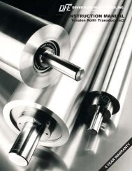
TENSION ROLL ®<br />
TRANSDUCERS<br />
5 YEAR WARRANTY
®<br />
TENSION ROLL TRANSDUCER<br />
The TR Tension Roll® Transducer accurately measures<br />
tension in any continuous web of paper, film, foil, textile or<br />
other material. It consists of a dead-shaft idler roll with tension<br />
sensors built into each end. This integrated construction<br />
makes installation of the Tension Roll® quick and<br />
easy on any dual-frame web press or machine.<br />
Choose from three available frame sizes: 0, 1, or 2, depending<br />
on your application requirements and machine geometry.<br />
The size 0 TR has a 2.25-inch diameter roll and a<br />
1-inch diameter shaft. The size 1 TR has a 3 inch diameter<br />
roll and a 1 inch diameter shaft. The size 2 TR can have a<br />
4, 5, or 6 inch diameter roll and a 1.125-inch diameter<br />
shaft.<br />
To allow measurement of an extremely wide tension<br />
range in a single location without the addition of an extra<br />
idler roll, the Tension Roll Transducer can be mounted in a<br />
pair of Model C dead-shaft tension transducers during installation.<br />
BENEFITS/FEATURES<br />
<br />
<br />
<br />
<br />
<br />
<br />
<br />
<br />
Tension transducers and idler roll are combined in one<br />
integral package. No assembly required.<br />
Faster and easier to install than separate roll and<br />
transducers. Requires no more space than an ordinary<br />
idler roll.<br />
Costs less than separate transducers and idler roll.<br />
Only one transducer cable. No cable needs to cross the<br />
machine.<br />
High overload capacity provided by time-proven<br />
“through-shaft" design.<br />
OPTIONS<br />
Counterbore, Drill, and Tap (CDT). Shaft ends are<br />
counterbored, drilled and tapped.<br />
Drill and Tap (D&T). Drill and tap ends of shaft.<br />
Sizes 0 and 1: 5/16-18 (8mm), Size 2: 1/2-13 (12mm).<br />
Extended Range Output (XR).<br />
Extra sensitive at low<br />
tensions. <strong>Electronics</strong> must also have extended range.<br />
Milled Flats (MF). Shaft with milled flats and a through<br />
hole at each end.<br />
SPECIFICATIONS:<br />
Excitation: 5 Vdc, regulated, 10Vdc with XR option<br />
Output: 500mVdc, nominal, 1 Vdc with XR option.<br />
Strain Gage Resistance: 100 ohms, nominal<br />
Non-Repeatability: ± 1/4% Full Span (FS)<br />
Combined Non-Linearity and Hysteresis:<br />
± 1/2% (FS)<br />
Temperature range: -10°F to 200°F (-23°C to 93°C)<br />
Temperature Coefficient: 0.02% per F° typical<br />
(0.036% per C°)<br />
Mating Electrical Connector: DFE Part No. 106-0050 for<br />
all sizes<br />
Electrical Connector Position: 6 o'clock<br />
Connector Pin Assignment: A = output; far end, B=5V+,<br />
C = 5V-, D = output; connector end, E= 5V-, F= 5V+<br />
Overload Capacity: Size0&1=880lbs. (3914 N),<br />
Size 2 = 3000 lbs. (13,300 N)<br />
<br />
<br />
<br />
<br />
<br />
<br />
<br />
Can be mounted in DFE dead shaft transducers to allow<br />
measurement of extremely wide tension range in one<br />
location without the need of an extra idler roll.<br />
Minimal transducer deflection does not affect the web.<br />
Measures actual web tension. Allows accurate and<br />
consistent display and control of tension.<br />
Installed the same as any dead shaft idler roll.<br />
Non-standard Shaft Extensions (NSE). Shaft extends<br />
longer or shorter or unequal lengths from ends of roll.<br />
Specify lengths.<br />
Oiled Bearings (OB). Oil instead of grease for<br />
lubrication.<br />
Reduced Diameter (RD3). Diameter of shaft is reduced<br />
to 3/4”. Used on TR0 and TR1 which have 1” shafts.<br />
Steel Roll (SR),<br />
or Stainless Steel (SSR) instead of<br />
standard aluminum roll.<br />
Deflection of Sensor Beam: Sizes 0 and 1 = 0.018 in.<br />
max. (0.46 mm), Size 2 - 0.008 in. max. (0.2 mm)<br />
Roll - Material: 6061 Aluminum; 304 Stainless Steel<br />
(option); 1020 Series Steel (option)<br />
TIR: 0.002 in. (0.05mm)<br />
Balance: Quality Grade G2.5 per ISO 1940 and<br />
ANSI S2-19-75<br />
Finish: 32µ inch<br />
Shaft: Stainless Steel, plain ends<br />
Load Ratings: Size 0 = 12, 25, 50, 100 lbs.<br />
(55, 110, 225, 450 N)<br />
Size 1 = 12, 25, 50, 100, 150 lbs.<br />
(55, 110, 225, 450, 670 N)<br />
Size 2 = 12, 25, 50, 100, 200, 400 lbs.<br />
(55, 110, 225, 450, 900, 1800 N)<br />
ACCESSORIES<br />
<br />
Shaft Hangers for Sizes 0 and 1, PN# 601-3118. Shaft Hangers for Size 2: PN# 601-1179
SELECTION OF LOAD RATING<br />
The correct transducer load rating for your application is<br />
determined by maximum web tension, wrap angle, and roll<br />
weight. Choose the appropriate wrap configuration from<br />
the diagrams below. Then compute the Net Force using the<br />
formula below the diagram. (The direction of the tension<br />
force determines which diagram and formula to use).<br />
In some cases, the load rating, may be less than the<br />
computed Net Force. This is acceptable because the Net<br />
Force formula contains an oversizing factor of 2, which<br />
means that the actual force exerted on the transducer will<br />
not exceed its load rating.<br />
Sometimes, a roll is so heavy that its weight uses up most<br />
of the operating range of the transducer. When this<br />
happens, it may not be possible to adjust the tension<br />
indicating meter to read zero when tension is zero<br />
because the adjustment range of the electronic circuit has<br />
been exceeded. To find out if the roll is too heavy,<br />
compare the load rating with the effective weight of the roll<br />
as follows: The effective roll weight is the "WCOS(A)"<br />
term in the formula. If WCOS(A) is more than 95% of the<br />
load rating chosen, the tension meter will probably not<br />
be adjustable to zero. If this is the case, one or more of<br />
the following changes must be made to reduce WCOS(A)<br />
to less than 95% of the load rating:<br />
1. Reduce the transducer roll weight<br />
2. <strong>Inc</strong>rease angle (A)<br />
3. Use the next higher load rating (This is the least<br />
desirable choice because it reduces transducer signal<br />
output).<br />
WRAP 3<br />
T below horizontal<br />
F T<br />
WRAP 1<br />
WRAP 2<br />
F WEB<br />
WEB<br />
T<br />
A<br />
Tension Force FT above horizontal Tension Force F<br />
Tension Force FT horizontal<br />
B<br />
C<br />
C/2<br />
B<br />
C<br />
C/2<br />
F T<br />
B<br />
A<br />
C<br />
W<br />
WEB<br />
W<br />
W<br />
LOAD<br />
RATING = B<br />
B<br />
B<br />
4T SIN ( W COS(A)<br />
2<br />
LOAD 4T SIN ( 2<br />
+ W COS(A)<br />
LOAD 4T SIN<br />
=<br />
RATING<br />
RATING =<br />
( 2<br />
2<br />
2<br />
2<br />
W = idler roll weight, T = Maximum web tension, B = Wrap angle = 180° - C°, A = Angle between Tension Force FT<br />
and vertical<br />
(<br />
(<br />
(<br />
TABLE 1<br />
ANGLE SINE COSINE<br />
0°<br />
5°<br />
10°<br />
15°<br />
20°<br />
25°<br />
30°<br />
35°<br />
40°<br />
45°<br />
50°<br />
55°<br />
60°<br />
65°<br />
70°<br />
75°<br />
80°<br />
85°<br />
90°<br />
0.000<br />
0.087<br />
0.174<br />
0.259<br />
0.342<br />
0.423<br />
0.500<br />
0.574<br />
0.643<br />
0.707<br />
0.766<br />
0.819<br />
0.866<br />
0.906<br />
0.940<br />
0.966<br />
0.985<br />
0.996<br />
1.000<br />
1.000<br />
0.996<br />
0.985<br />
0.966<br />
0.940<br />
0.906<br />
0.866<br />
0.819<br />
0.766<br />
0.707<br />
0.643<br />
0.574<br />
0.500<br />
0.423<br />
0.342<br />
0.259<br />
0.174<br />
0.087<br />
0.000<br />
MAXIMUM ALLOWABLE ROLL WIDTH inches (mm), see Note 1.<br />
SIZE 0<br />
ALUMINUM<br />
STEEL<br />
STAINLESS STEEL<br />
LOAD RATING<br />
Roll Diameter inch (mm)<br />
Roll Diameter inch (mm)<br />
Roll Diameter inch (mm)<br />
lb. (N)<br />
12 (55)<br />
25 (110)<br />
50 (225)<br />
100 (450)<br />
Roll Weight lb/in (kg/cm)<br />
2.25 (57)<br />
40 (1016)<br />
40 (1016)<br />
40 (1016)<br />
34 (864)<br />
0.16 (0.03)<br />
2.25 (57)<br />
40 (1016)<br />
40 (1016)<br />
40 (1016)<br />
40 (1016)<br />
0.45 (0.08)<br />
2.25 (57)<br />
40 (1016)<br />
40 (1016)<br />
40 (1016)<br />
40 (1016)<br />
0.45 (0.08)<br />
Weight of Bearing Assemblies is 0.3 lbs. (0.136 kg.) total. Minimum width of roll is 6 inches (152 mm).<br />
SIZE 1<br />
ALUMINUM<br />
STEEL<br />
STAINLESS STEEL<br />
LOAD RATING<br />
Roll Diameter inch (mm)<br />
Roll Diameter inch (mm)<br />
Roll Diameter inch (mm)<br />
lb. (N)<br />
12 (55)<br />
25 (110)<br />
50 (225)<br />
100 (450)<br />
150 (670)<br />
Roll Weight lb/in (kg/cm)<br />
3 (76)<br />
50 (1270)<br />
50 (1270)<br />
50 (1270)<br />
44 (1118)<br />
36 (914)<br />
0.30 (0.054)<br />
3 (76)<br />
50 (1270)<br />
50 (1270)<br />
50 (1270)<br />
50 (1270)<br />
50 (1270)<br />
0.88 (0.157)<br />
3 (76)<br />
50 (1270)<br />
50 (1270)<br />
50 (1270)<br />
50 (1270)<br />
50 (1270)<br />
0.88 (0.157)<br />
Weight of Bearing Assemblies is 1.4 lbs. (0.63 kg.) total. Minimum width of roll is 6 inches (152 mm).<br />
SIZE 2<br />
LOAD RATING<br />
ALUMINUM<br />
Roll Diameter inch (mm)<br />
STEEL or STAINLESS STEEL<br />
Roll Diameter inch (mm)<br />
lb. (N)<br />
12 (55)<br />
25 (110)<br />
50 (225)<br />
100 (450)<br />
200 (900)<br />
400 (1800)<br />
Roll Weight lb/in (kg/cm)<br />
4 (102)<br />
112 (2845)<br />
112 (2845)<br />
100 (2450)<br />
84 (2134)<br />
69 (1753)<br />
51 (1295)<br />
0.54 (0.096)<br />
5 (127)<br />
120 (3048)<br />
120 (3048)<br />
120 (3048)<br />
120 (3048)<br />
95 (2413)<br />
73 (1854)<br />
0.69 (0.124)<br />
6 (152)<br />
120 (3048)<br />
120 (3048)<br />
120 (3048)<br />
120 (3048)<br />
120 (3048)<br />
95 (2413)<br />
0.85 (0.152)<br />
4 (102)<br />
120 (3048)<br />
120 (3048)<br />
120 (3048)<br />
120 (3048)<br />
96 (2438)<br />
79 (2007)<br />
1.56 (0.279)<br />
5 (127)<br />
120 (3048)<br />
120 (3048)<br />
120 (3048)<br />
120 (3048)<br />
120 (3048)<br />
100 (2540)<br />
2.00 (0.357)<br />
6 (152)<br />
120 (3048)<br />
120 (3048)<br />
120 (3048)<br />
120 (3048)<br />
120 (3048)<br />
120 (3048)<br />
2.44 (0.437)<br />
Weight of Bearing Assemblies is 4.3 lbs. (1.9 kg.) total. Minimum width of roll is 7 inches (178 mm).<br />
1.Roll may be too heavy for the load rating. Be sure to check the sizing criteria and formulas<br />
2.Use the std. sizing formulas to determine the correct load rating. In the formulas, "W" is equal to the roll weight plus the weight of the bearing assemblies.<br />
3.Standard maximum roll width is 120 inches. Wider rolls are available on special order at an additional cost. Consult factory. Shorter widths limit roll deflection.
DIMENSIONS<br />
inches (mm)<br />
B<br />
G C<br />
G (1)<br />
D<br />
E<br />
(1)<br />
(2)<br />
F<br />
A<br />
SIZE 0<br />
SIZE 1<br />
SIZE 2<br />
in.<br />
mm<br />
in.<br />
mm<br />
in.<br />
mm<br />
Ø 1.00<br />
Ø 25.4<br />
Ø 1.00<br />
Ø 25.4<br />
®<br />
TENSION ROLL TRANSDUCER<br />
A B C D E<br />
Ø 1.125<br />
Ø 28.58<br />
*<br />
*<br />
*<br />
*<br />
*<br />
*<br />
*<br />
*<br />
*<br />
*<br />
*<br />
*<br />
* Specified at time of order<br />
(1) (2)<br />
Notes: Can be changed upon request. Size 2 is available with Ø 4.00” standard roll or optional Ø 5.00” ( Ø 127) or Ø 6.00” ( Ø 152.4) roll.<br />
0.31<br />
7.9<br />
0.31<br />
7.9<br />
0.31<br />
7.9<br />
1.30<br />
33<br />
1.26<br />
32<br />
1.26<br />
32<br />
F (2)<br />
Ø 2.25<br />
Ø 57.1<br />
Ø 3.00<br />
Ø 76.2<br />
Ø 4.00<br />
Ø 101.6<br />
G<br />
3.00<br />
76.2<br />
3.00<br />
76.2<br />
4.00<br />
101.6<br />
F<br />
E<br />
D<br />
Ø 5.00 Ø 127<br />
J<br />
C<br />
G<br />
G<br />
H<br />
L<br />
K<br />
B<br />
A<br />
SIZE 0<br />
(#601-3118)<br />
SIZE 1<br />
(#601-3118)<br />
SIZE 2<br />
(#601-1179)<br />
PRODUCT CODE<br />
You may order by description or by specifying the code below by matching each labeled digit with your choice. Please<br />
specify Roll Length and Shaft Length (in inches).<br />
Example: TR2-4-100-6-SR, D&T Roll Length = 32.5", Shaft Lengh = 42.5"<br />
NOTES:<br />
1. Size 1 only<br />
2. Size 2 only<br />
3. Load direction<br />
is assumed at 6 o'clock.<br />
4. XR option requires that<br />
electronics have XRE option.<br />
in.<br />
mm<br />
in.<br />
mm<br />
in.<br />
mm<br />
SIZE<br />
0<br />
1<br />
2<br />
©2010 DOVER FLEXO ELECTRONICS, INC.<br />
ALL RIGHTS RESERVED<br />
4.00<br />
101.6<br />
4.00<br />
101.6<br />
4.00<br />
101.6<br />
3.00<br />
76.2<br />
3.00<br />
76.2<br />
3.00<br />
76.2<br />
TRX - X - XXX - X - X,X,X<br />
ROLL<br />
DIAMETER<br />
2.25 (std Sz 0 only)<br />
3 (std Sz 1 only)<br />
4 (std Sz 2)<br />
5 (opt Sz 2 only)<br />
6 (opt Sz 2 only)<br />
OTHER (Specify)<br />
SHAFT HANGERS FOR TRANSDUCERS<br />
A B C D E F G H J K L<br />
3.00<br />
76.2<br />
3.00<br />
76.2<br />
3.00<br />
76.2<br />
1.84<br />
46.7<br />
1.84<br />
46.7<br />
1.84<br />
46.7<br />
LOAD<br />
RATING<br />
12 lb.<br />
25 lb.<br />
50 lb.<br />
100 lb.<br />
1<br />
150 lb.<br />
2<br />
200 lb.<br />
2<br />
400 lb.<br />
2.20<br />
56<br />
2.20<br />
56<br />
2.20<br />
56<br />
CONNECTOR<br />
POSITION<br />
6:00 (Std)<br />
12:00<br />
0.80<br />
20.3<br />
0.80<br />
20.3<br />
0.80<br />
20.3<br />
1.75<br />
44.45<br />
1.75<br />
44.45<br />
1.75<br />
44.45<br />
0.43<br />
10.9<br />
0.43<br />
10.9<br />
0.43<br />
10.9<br />
Ø 1.00<br />
Ø 25.4<br />
Ø 1.00<br />
Ø 25.4<br />
OPTIONS (Separated by commas)<br />
CDT = Counterbore, Drill and Tap<br />
D&T = Drill & Tap<br />
MF = Milled Flats<br />
NSE = Non-std Shaft Extensions<br />
OB = Oiled Bearings<br />
RD3 = Reduced Diameter of Shaft to 3/4”<br />
SR = Steel Roll<br />
SSR = Stainless Steel Roll<br />
4<br />
XR = Extended Range<br />
Z= Special (SPR)<br />
T H E T E N S I O N C O N T R O L S P E C I A L I S T S<br />
DOVER FLEXO ELECTRONICS, INC.<br />
217 PICKERING ROAD, ROCHESTER, NH 03867 USA 603-332-6150 FAX 603-332-3758<br />
E-Mail: info@dfe.com Internet: www.dfe.com<br />
Ø 1.125<br />
Ø 28.58<br />
Ø 0.34<br />
Ø 8.6<br />
Ø 0.34<br />
Ø 8.6<br />
Ø 0.34<br />
Ø 8.6<br />
1.18<br />
29.9<br />
1.18<br />
29.9<br />
1.18<br />
29.9<br />
DOC 802-0630 R6<br />
PRINTED IN USA