INSTRUCTION MANUAL - Dover Flexo Electronics, Inc
INSTRUCTION MANUAL - Dover Flexo Electronics, Inc
INSTRUCTION MANUAL - Dover Flexo Electronics, Inc

You also want an ePaper? Increase the reach of your titles
YUMPU automatically turns print PDFs into web optimized ePapers that Google loves.
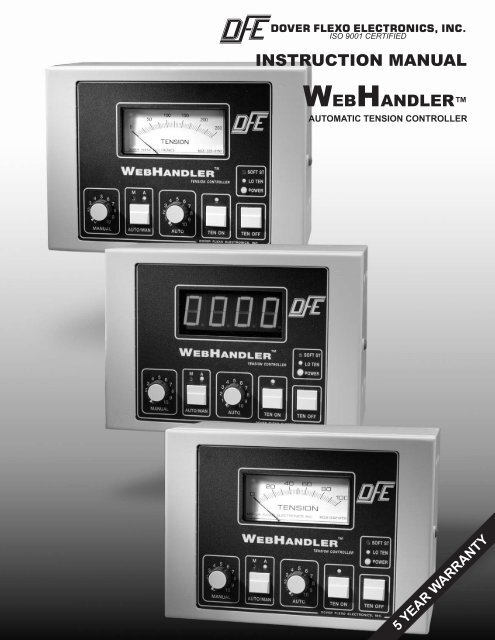
DOVER FLEXO ELECTRONICS, INC.<br />
ISO 9001 CERTIFIED<br />
<strong>INSTRUCTION</strong> <strong>MANUAL</strong><br />
W<br />
EB<br />
H<br />
ANDLER<br />
AUTOMATIC TENSION CONTROLLER<br />
5 YEAR WARRANTY
217 Pickering Road<br />
Rochester, NH 03867-4630 U.S.A.<br />
For assistance, please call:<br />
TECHNICAL SERVICE - Installations, Start-Up, Troubleshooting, Repairs, Field<br />
Service, Returns. techsupport@dfe.com<br />
CUSTOMER SERVICE - Replacement Parts, Individual Products, Questions about<br />
Orders, Manuals. customerservice@dfe.com<br />
SALES - Product Information, Systems Application Questions, and<br />
placing orders for standard products and special<br />
systems. sales@dfe.com<br />
Telephone: (603) 332-6150 Fax: (603) 332-3758<br />
E-mail: info@dfe.com Internet: www.dfe.com<br />
©2006 <strong>Dover</strong> <strong>Flexo</strong> <strong>Electronics</strong>, <strong>Inc</strong>. All rights reserved. <strong>Dover</strong> <strong>Flexo</strong> <strong>Electronics</strong> has made reasonable effort to ensure accuracy of this<br />
document. However NO WARRANTY, whether expressed or implied, is given regarding the completeness or correctness of information in<br />
this document. <strong>Dover</strong> <strong>Flexo</strong> <strong>Electronics</strong> shall not be liable for damages of any kind arising from the use or misuse of this document. <strong>Dover</strong><br />
<strong>Flexo</strong> <strong>Electronics</strong> reserves the right to make changes, additions, and deletions to this document without notice and without obligation.
READ THIS!<br />
Your WebHandler Controller has been properly configured at our factory. To<br />
install it and start it up, it should only be necessary to use these sections of this<br />
manual:<br />
Section 2 - Installation<br />
Section 3 - Calibration and Set-Up<br />
The other sections are for reference and for instruction if you wish to change the<br />
configuration at some later time.
EXAMPLE OF TENSION ZONES<br />
TRANSDUCER<br />
ROLL<br />
INFEED<br />
DRIVEN NIP<br />
ROLLS<br />
TRANSDUCER<br />
ROLL<br />
TRANSDUCER ROLL<br />
(ALTERNATE LOCATION FOR<br />
INTERMEDIATE ZONE)<br />
OUTFEED DRIVEN<br />
NIP ROLLS<br />
TRANSDUCER ROLL<br />
BRAKE<br />
PROCESS<br />
WebHandler<br />
P<br />
TACH<br />
M<br />
MOTOR<br />
TACH (Option)<br />
M<br />
MOTOR<br />
WebHandler<br />
V<br />
VARIABLE SPEED<br />
DRIVE OR CLUTCH<br />
MOTOR<br />
CONTROL<br />
MAIN DRIVE<br />
SETS WEB SPEED<br />
WebHandler<br />
D<br />
MOTOR<br />
CONTROL<br />
UNWIND ZONE INTERMEDIATE ZONE REWIND ZONE<br />
Tension zones are created by driven or braked nip rolls, drag bars, braked or driven unwind or rewind<br />
shafts, or anything else that can increase or decrease web tension. One of these elements is at each<br />
end of every tension zone.<br />
Many machines that process a continuous web have more than one tension zone. The WebHandler<br />
controller can be used in all tension zones, however it may need to be configured for the zone it will be<br />
used in. The information below will be used later to determine the correct configuration.
TABLE OF CONTENTS<br />
SECTION ONE DESCRIPTION PAGE<br />
1.1 General Description ........................................ 1<br />
1.2 Outputs, Version of Controller ................................ 1<br />
1.3 WebHandler Controller Exploded View ....................... 2<br />
1.4 Specifications ............................................. 2<br />
1.5 Standard Features ......................................... 3<br />
1.6 Options ................................................. 3<br />
1.7 Front Panel & Operator Devices .............................. 4<br />
SECTION TWO INSTALLATION<br />
2.1 Standard Dimensions ...................................... 5<br />
Dimensions of Remote Panel Configuration .................... 5<br />
Dimensions of Remote Servo Valve Enclosure .................. 6<br />
2.2 Selection of Mounting Location ............................... 6<br />
2.3 Installation Instructions ..................................... 6<br />
2.4 Power Voltage ............................................ 7<br />
2.5 Transducer Excitation ...................................... 7<br />
2.6 Std. Electrical Connections .................................. 7<br />
2.7 Electrical Connections for Options ............................ 8<br />
SECTION THREE CALIBRATION AND SETUP<br />
3.1 Mechanically Zero the Tension Meter .......................... 9<br />
3.2 Calibrate the Meter for Accuracy .............................. 9<br />
3.3 Meter Damping............................................ 9<br />
3.4 10 Volt Output ............................................ 10<br />
3.5 Digital Meter Option ........................................ 10<br />
3.6 Emergency Stop ........................................... 11<br />
3.7 Extended Range Option ..................................... 12<br />
3.8 High Voltage Output ........................................ 12<br />
3.9 Isolated 10 Volt Output Option................................ 12<br />
3.10 Line Speed Follow ......................................... 13<br />
3.11 Meter Correlation .......................................... 14<br />
3.12 Pneumatic Output / Remote Pneumatics in Enclosure ............. 14<br />
3.13 Remote Tension Amplifier Option ............................. 16<br />
3.14 Reverse Output Option ..................................... 16<br />
3.15 Soft Start ................................................ 16<br />
3.16 Taper Tension / 10 Volt Taper Card Option ..................... 18<br />
3.17 Tension Limit Switch ....................................... 19<br />
3.18 Tuning Adjustments ........................................ 19<br />
SECTION FOUR OPERATING <strong>INSTRUCTION</strong>S .......................... 21<br />
SECTION FIVE CARE AND MAINTENANCE ............................ 22<br />
SECTION SIX TROUBLESHOOTING GUIDE .......................... 23<br />
SECTION SEVEN REPLACEMENT PARTS<br />
7.1 Standard Circuit Boards ..................................... 24<br />
7.2 Optional Circuit Boards ..................................... 24<br />
7.3 Operator Devices .......................................... 24<br />
7.4 Output Modules ........................................... 24<br />
7.5 Fuses ................................................... 24<br />
7.6 Cables .................................................. 24<br />
7.7 Relays .................................................. 24
APPENDICES<br />
A PC Boards ............................................... 25<br />
B DIP Switch Settings & Jumpers ............................... 29<br />
C Basic Set-up Sequence ..................................... 30<br />
D Transducer Electrical Connections ............................ 31<br />
E Typical Tensions .......................................... 35<br />
Terms and Conditions ...................................... 36<br />
Index .................................................... 37<br />
LIST OF ILLUSTRATIONS<br />
1. Web Handler Controller - Exploded View ....................... 2<br />
2. Front Panel and Operator Devices ............................ 4<br />
3. Standard Dimensions ....................................... 5<br />
4. Remote Panel Dimensions .................................. 5<br />
5. Dimensions Servo Valve Enclosure ........................... 6<br />
6. Power Voltage Switch ...................................... 7<br />
7. Transducer Excitation Switch ................................ 7<br />
8. Electrical Connections ...................................... 7<br />
9. Electrical Connections of Options ............................. 8<br />
10. Web Path ................................................ 9<br />
11. 10 Volt Output Jumpers ..................................... 10<br />
12. Digital Meter Display ....................................... 10<br />
13. Digital Meter Card ......................................... 10<br />
14. Digital Meter Switches ...................................... 11<br />
15. E-Stop Electrical Connections & Switch Settings ................. 11<br />
16. Transducer Excitation Voltage................................ 12<br />
17. High Voltage Output Switch Settings ........................... 12<br />
18. 10 Volt Isolated Output Connections ........................... 12<br />
19. Line Speed Follower Electrical Connections ..................... 13<br />
20. Line Speed Follower Switch Settings .......................... 13<br />
21. Remote Pneumatic Connections .............................. 14<br />
22. Non-DFE Pneumatic Driver .................................. 15<br />
23. Remote Tension Amp Switches .............................. 16<br />
24. Remote Tension Amp Connections ............................ 16<br />
25. Reverse Output Switch Settings .............................. 16<br />
26. Soft Start by Low Tension Switch Settings ...................... 17<br />
27. Soft Start by External Contact Connections ..................... 17<br />
28. Soft Start by External Contact Switch .......................... 17<br />
29. Taper Tension Rider Option Card ............................. 18<br />
30. Rider Roll Connections ..................................... 18<br />
31. 10 Volt Source Connections ................................. 18<br />
32. Tension Limit Switch Settings ................................ 19<br />
33. Tuning Adjustment Pots. .................................... 20<br />
34. Control Board ............................................. 25<br />
35. Power Board ............................................. 25<br />
36. Front Board .............................................. 26<br />
37. V-Out Board .............................................. 26<br />
38. Non-DFE Driver Module ..................................... 27<br />
39. Isolated Output Board ...................................... 27<br />
40. Line Speed Follower Board .................................. 28<br />
41. Taper Tension Board ....................................... 28<br />
42. C, UPB Transducer Wiring .................................. 31<br />
43. RF Transducer Wiring ...................................... 32<br />
44. TR, NW Transducer Wiring .................................. 33<br />
45. LT Transducer Wiring ...................................... 34
SECTION 1<br />
PRODUCT DESCRIPTION<br />
1.1 GENERAL DESCRIPTION<br />
The WebHandler tension controller automatically maintains tension of any continuous material at the value<br />
selected by the machine operator. It provides three basic functions:<br />
The first function is performed by the tension amplifier, which supports all <strong>Dover</strong> <strong>Flexo</strong> <strong>Electronics</strong> tension<br />
transducers. (The transducers measure the actual tension in the web). It includes a regulated power supply to<br />
excite the transducers, an amplifier to boost the transducer output signal, and a calibration circuit to adjust the<br />
tension readout to display actual tension.<br />
The second function is the tension regulator. It compares the output signal from the transducers with the signal<br />
from the AUTO Set potentiometer on the front of the WebHandler enclosure. If there is a difference, the<br />
regulator will either increase or decrease its output signal to equalize them. The tension amplifier is located on<br />
the front board and the tension regulator is located on the Control board. (See Figure 1 for board locations, and<br />
Appendix A for board views)<br />
The third function is performed by the output circuit. It accepts the output from the tension regulator and<br />
actuates a brake, clutch, or DC drive which actually creates the tension in the web.<br />
There is a location on the Control board for plug-in cards containing optional features.<br />
1.2 OUTPUTS, VERSION OF CONTROLLER<br />
The WebHandler controller is available with one of three outputs:<br />
1. Pneumatic output. This is used to actuate any air operated brake or clutch. The standard version includes<br />
a servo valve and pressure regulator installed in an open back enclosure, plus a driver circuit card. An air<br />
filter may be supplied by the user and installed externally to the controller depending on the pneumatics<br />
chosen. The output range is 0.5 to 75 psi.(0.03 bar to 5.17 bar). WebHandler controllers having this<br />
module are designated Version P.<br />
2. High Voltage output. This output circuit uses Silicon Controlled Rectifiers (SCR’s) to produce a standard<br />
variable voltage of up to 90 volts DC to operate any electric brake or clutch, including eddy current clutches.<br />
45 volt, and 24 volt outputs (24V not available with 230Vac input) are optional. WebHandler controllers<br />
having this output module are designated Version V.<br />
3. 0-10Volt DC compensated output module. This output is used to control DC drives or other variable<br />
speed drive systems. This output is isolated from earth ground to make it more compatible with all drives.<br />
WebHandler controllers having this output module are designated Version D.<br />
4. Driver Card. This version provides power and signal outputs for non-standard pneumatic servo valves and<br />
is designated Version C.<br />
Versions P, V, and D have a secondary output of 4 to 20mA. The C version may use this as its primary output.<br />
If not, it is available as a secondary output.<br />
In addition to the standard enclosure, the WebHandler controller is available in an optional configuration<br />
called a Remote Panel. This is normally used by OEMs who wish to integrate the controller into their own<br />
electrical enclosures. See Section 1.6, Options for more info.<br />
1
1.3 WebHandler EXPLODED VIEW<br />
Figure 1 - WebHandler EXPLODED VIEW<br />
1.4 SPECIFICATIONS (separated into Versions V, D, P or C where applicable)<br />
Power input:<br />
P , D, & C = 115/230 Volts 60/50Hz single phase @ 1<br />
Amp<br />
V = 115/230 Volts 60/50Hz single phase @ 6 Amps<br />
Output:<br />
P = 0.5 to 75 psi (0.03 to 5.17 bar)<br />
V = 90, 45, or 24 Vdc, all @ 5 Amp w/115 Vac In OR<br />
90 Vdc, 45 Vdc all @ 5 Amp w/230 Vac In<br />
D = 0 to ±10 Vdc, Compensated (Optional Isolated)<br />
C = +15Vdc @ 250mAdc to power a servo valve<br />
24Vac/dc @ 200 mA to power a servo valve<br />
0-10Vdc @ 2mA to control the valve<br />
1 to 5Vdc @ 2mA to control the valve<br />
4-20mA to control the valve<br />
P, V, D = 4-20mA Control Output Signal AND<br />
choice of 0-10Vac or 0-1mA tension<br />
indication to external device.<br />
Enclosure:<br />
Steel, powder resin painted, NEMA 1<br />
Weight:<br />
9 lbs. (4.1 kg)<br />
Transducer Signal Accepted:<br />
500 mVdc per pair at rated load<br />
(1000 mV with XR option)<br />
Mating Transducer Cable Connectors:<br />
Amphenol MS3106A-10SL-3S<br />
Zero (Tare) Range:<br />
95% of transducer rating, minimum<br />
Calibration Range:<br />
25:1 max.<br />
Temperature Range:<br />
32° F to 104° F (0° C to 40° C)<br />
System Accuracy:<br />
within 1 - 3% typical<br />
Tension Meter:<br />
Analog, 2%, 1mA, 48 ohm<br />
Output Range:<br />
0-100% Max.<br />
Manual Mode Output Range:<br />
0-100% of rated output<br />
Standard Tension Meter Scales:<br />
0 - 1, 5, 10, 25, 50, 100, 150, 250, 500, 1000<br />
Taper Tension Range (option):<br />
0-100%<br />
Taper Tension by Rider Roll / Diameter Sensor<br />
0-10 Vdc input<br />
Pneumatics Enclosure:<br />
Input: 125 psi Max.<br />
Output: 0.5 to 75 psi (0.03 to 5.17 bar)<br />
Servo Valve Drive Signal: 0-100mA<br />
Air Connections: In = 1/4 NPT, Out = 1/8 NPT<br />
Weight: 2.84 lbs. (1.28 kg.)<br />
2
1.5 STANDARD FEATURES<br />
SOME OF THESE FUNCTIONS REQUIRE CONFIGURING OR EXTERNAL WIRING. REFER TO SECTION 3 FOR<br />
CONFIGURING AND SECTION 2.6 FOR WIRING.<br />
• 4-20mA CONTROL OUTPUT for monitoring/recording of control signal.<br />
• AUTOMATIC CONTROL MODE. The controller output is determined by the difference between web tension<br />
and the AUTO tension set pot. position. The internal regulator automatically varies the output as required to<br />
maintain set tension.<br />
• EMERGENCY STOP. Controller immediately goes to full output, or minimal output, upon closure of an<br />
external contact. Normally full output is used on braked unwinds to stop the roll of material quickly, and<br />
minimum output is used for other applications.<br />
• EXTERNAL TENSION READOUT. Jumper selectable 0-10Vdc or 0-1mA external meter or monitoring<br />
output. Buffered to prevent load from affecting controller.<br />
• <strong>MANUAL</strong> CONTROL MODE. The controller output is determined only by the position of the <strong>MANUAL</strong> set<br />
knob. No change occurs unless the knob is turned. Used during machine set-up or during trouble-shooting.<br />
• METER CORRELATION ADJUSTMENT. This causes the position of the AUTO set pot to correspond to the<br />
position of the needle on the analog tension meter. For example; if the AUTO set pot is set at 4 on its dial,<br />
the tension meter will read 40% of full scale. This is important for the proper operation of the controller.<br />
This is preset during factory setup and should not be tampered with. Call Tech Support prior to changing<br />
this.<br />
• METER DAMPING. Eliminates vibration of the analog tension meter needle. Also minimizes flicker of the<br />
optional digital meter.<br />
• OUTPUT DIRECTION. Select between standard and reverse output. Most applications use the standard<br />
selection where controller output goes up when tension falls below the set level. Reverse selection causes<br />
output to go down when tension falls below the set level. It is used in intermediate tension zones where the<br />
transducers are located after the nip rolls they control, and for driven unwinds.<br />
• POWER VOLTAGE SELECTION. The WebHandler controller is designed to operate on two ranges of AC<br />
power; 110-120 Volts 60/50 Hz, and 220-240 Volts 60/50 Hz. A voltage selection switch on the Power Board<br />
selects between the two.<br />
• SERVO VALVE ASSEMBLY. Standard for Version P. Allows servo valve to be installed close to the<br />
brake/clutch while the controller is located elsewhere. <strong>Inc</strong>ludes servo valve, regulator, and enclosure. Not<br />
included in Version C.<br />
• SOFT START. Used on braked unwinds. Actuated either automatically upon a loss of tension below the<br />
preset trip point (after an adjustable delay), or immediately upon an external contact closure. Controller<br />
output is reduced to a preset (user adjustable) low level to prevent brake lock-up when the machine starts.<br />
When tension rises above the trip point in automatic trip mode, the controller goes back to the automatic<br />
control mode. Unit remains in Soft Start while contact remains closed. Does not operate in the <strong>MANUAL</strong><br />
control mode.<br />
• STATUS LIGHTS. Show that particular functions are active when lights are illuminated.<br />
• TENSION DISPLAY. Web tension is displayed on an analog meter which is calibrated to read out total<br />
tension in pounds, newtons, kilograms, or any other desired units. A digital meter is optional.<br />
• TENSION LIMIT SWITCH. Both an LED and a relay are activated to alert operators to low tension condition.<br />
1.6 OPTIONS<br />
SOME OF THESE OPTIONAL FUNCTIONS REQUIRE CONFIGURING OR EXTERNAL WIRING. REFER TO SECTION 3<br />
FOR CONFIGURING AND SECTION 2.7 FOR WIRING.<br />
• 230 VOLT POWER (230). 230 volt 50/60 Hz power input.<br />
• 24V or 45V OUTPUT (24,45). All for Version V only. 24V with 115Vac only.<br />
• ATTACHED POWER CORD (APC). A heavy duty 3 conductor power cord wired to the unit .<br />
• DIGITAL METER (DM). 4 full digits, red 1" high LED's with over and under range indicators. The<br />
maximum range is 0000 to 9999. An over-range indicator lights at values over 9999, and an under-range<br />
indicator lights at values below 0. Can be read from further away than the analog meter and is switchable to<br />
select fewer digits and decimals.<br />
3
• EXTENDED RANGE (XRE). The transducers are excited by 10 volts instead of the standard 5 volts. Used<br />
for low tension applications, or applications with very wide tension ranges. The transducers must also have<br />
the XR option.<br />
• ISOLATED 10V OUTPUT (I10). Isolates the output signal from ground or circuit common. Version D only.<br />
Recommended for all units connecting to drives or PLC’s.<br />
• METRIC PNEUMATIC FITTINGS (MPF). Metric size air fittings in place of inch size.<br />
• NONSTANDARD METER SCALE (NMS). Any nonstandard analog meter scale. Either single or dual scale.<br />
See Specifications, page 2, for standard scales.<br />
• REVERSE OUTPUT (RO). <strong>Inc</strong>reases output when tension exceeds set point, and decreases when tension<br />
drops below set point. Used in intermediate applications where transducers are located after the nip rolls<br />
being controlled by the transducers or for driven unwinds.<br />
• REMOTE OPERATOR PANEL CONFIGURATION (ROP). This configuration consists of the Control, Power<br />
and Output boards mounted in a standard enclosure and the and Front board connected to the controller by a<br />
wire harness or ribbon cable. The Front board is mounted on a special steel panel. This arrangement permits<br />
installation of the controller inside another enclosure with the front panel mounted in a rectangular cutout in<br />
the face of the enclosure.<br />
• REMOTE TENSION AMPLIFIER (RTA). The internal tension amplifier is bypassed and the tension signal is<br />
provided by an external remote device such as the FireGuard. This allows use of special indicator<br />
functions, such as intrinsic safety, which are not available in the WebHandler controller.<br />
• REMOTE TENSION SWITCH (RTS). Tension On/Off switch installed in remote enclosure, usually with<br />
servo valve.<br />
• SPEED FOLLOW (SFD). This is a function normally used on Version WH-D controlling tension in an<br />
intermediate zone or surface driven rewinds and unwinds. The controller must be equipped with an optional<br />
Line Speed Follower board.<br />
The Control board contains a regulator circuit, separate from the tension regulator, that accepts a line speed<br />
signal from a DC tach. The line speed signal causes the output of the controller to follow (go up and down<br />
with) line speed. The output of the tension regulator then trims the follower output as needed to maintain set<br />
tension.<br />
• TAPER TENSION (TTF). For rewind applications. Causes tension to decrease as roll diameter increases.<br />
Helps produce a better quality roll by eliminating telescoping, crushed cores, too tight or too loose rolls. The<br />
methods available are rider roll or diameter sensor such as an ultrasonic device. The rider roll method<br />
without an ultrasonic unit requires a follower roll in contact with the rewinding roll, or some other rollsensing<br />
device to detect the roll diameter. The device must have a 0-10 Volt DC output. Taper is adjustable<br />
from 0 to 100%. The taper circuitry is located on an option card which is plugged into the Control Board.<br />
1.7 FRONT PANEL AND OPERATOR DEVICES<br />
Figure 2 - FRONT PANEL and OPERATOR DEVICES<br />
4
SECTION 2<br />
INSTALLATION<br />
2.1 DIMENSIONS OF STANDARD UNIT inches (mm)<br />
Figure 3 - STANDARD DIMENSIONS<br />
DIMENSIONS OF REMOTE PANEL CONFIGURATION inches (mm)<br />
Enclosure dimensions listed above.<br />
Figure 4 - REMOTE PANEL DIMENSIONS<br />
5
DIMENSIONS OF PNEUMATICS ENCLOSURE - Version P<br />
inches (mm)<br />
Figure 5 - DIMENSIONS OF SERVO VALVE ENCLOSURE<br />
2.2 SELECTION OF A MOUNTING LOCATION<br />
1. Mounting Location for Versions P, V, C and D: Select a location on the machine frame or a wall that will<br />
be convenient for the machine operator to operate the controller and to see the tension meter easily. Be sure<br />
the location is free of vibration, and is dry and clean. Take care to choose a place that the controller won't be<br />
struck and damaged by anything or anyone.<br />
2. Mounting Location for Pneumatic Unit (Version P only): The Pneumatic unit is designed for mounting<br />
close to your brake or clutch. They will therefore require shop air to be brought to their input, and the output<br />
is brought to the clutch or brake. In addition, a connection cable must be run between the pneumatic unit and<br />
the controller. Choose a location which is free from vibration. For more reliable operation, you should<br />
consider installing an inline filter assembly to keep oil and water from entering the pneumatic assembly.<br />
2.3 INSTALLATION <strong>INSTRUCTION</strong>S<br />
1. Installation of Versions P, V, C and D: The enclosure is fastened to the mounting surface you have chosen<br />
by two socket head cap screws. Install the screws on the mounting surface to match the screw hole<br />
dimensions on the back surface of the WebHandler enclosure. See Section 2.1, Standard Dimensions.<br />
Leave them loose about 6 turns. Position the keyholes in the back panel of the enclosure over the screws and<br />
slide it down until it locks in place. The cover must be opened to tighten the mounting screws.<br />
In addition to the standard enclosure, the WebHandler controller is available in optional Remote Panel<br />
configuration. Use the above instructions to install the enclosure part of the configuration. Then refer to<br />
Section 2.1, Remote Panel Dimensions. Use the dimensions shown to measure the cut-out and screw<br />
locations and mount with the appropriate fitting hardware.<br />
2. Installation of Pneumatic Unit (Version-P only): This unit should be attached to your machine in the area<br />
of your clutch or brake. Drill four holes in a pattern 4" W x 7 1/2" H. Use four screws to attach the<br />
Pneumatic Unit to your machine. If you are using an oil and water filter, install it in close proximity to the<br />
Pneumatic Unit, following the instructions that come with the filter assembly.<br />
6
2.4 POWER VOLTAGE<br />
The WebHandler controller is designed to operate on either 115v-60Hz or 230v-50/60Hz power. Confirm that<br />
the correct voltage for your application has been selected. The AC voltage select switch is located on the power<br />
board. Slide switch to select 115 volts or 230 volts. Also verify that the correct fuses are used for the voltage<br />
you have selected. See figure below. CAUTION! The wrong selection will damage the controller!<br />
Figure 6 - POWER VOLTAGE SWITCH<br />
2.5 TRANSDUCER EXCITATION<br />
Confirm that the correct transducer excitation has been selected. 5 Volts is standard, 10 Volts provides a wider<br />
operating range. The transducer excitation select switch is located on the power board. CAUTION - The<br />
transducers MUST have the XR option if you select 10 Volts! Otherwise damage will result!<br />
Figure 7 - TRANSDUCER EXCITATION SWITCH<br />
2.6 STANDARD ELECTRICAL CONNECTIONS<br />
Refer to the drawing below for electrical connections. If your controller has any optional equipment, refer to<br />
Section 3 of this manual for the appropriate connections.<br />
Figure 8 - ELECTRICAL CONNECTIONS<br />
7
2.7 ELECTRICAL CONNECTIONS OF OPTIONS<br />
The connections below are options that hook up to the control board. Some options also connect to their own<br />
boards. Refer to specific options in Section 3 for electrical connections and switch settings as well as the<br />
location of the connections.<br />
Figure 9 - ELECTRICAL CONNECTIONS OF OPTIONS<br />
8
SECTION 3<br />
CALIBRATION and SET-UP<br />
Your WebHandler controller has been properly configured at the factory. It should not be necessary to make<br />
any changes except tension calibration and PID tuning. Use this section to verify the configuration or to<br />
reconfigure the controller if your application requirements change.<br />
3.1 MECHANICALLY ZERO THE TENSION METER<br />
This step is only necessary if the tension meter needle does not rest on 0 when the controller power is turned off.<br />
Push the POWER button to turn off power to the controller. Open the controller cover so the front board is<br />
accessible. Turn the adjustment screw on the rear of the meter as required to set the meter needle at 0 on the<br />
scale. (See section 3.5 to calibrate the optional digital meter.)<br />
Note for UPB-type transducers: As web tension is applied, the tension needle (or the reading on the digital<br />
meter) should increase. If it goes downward instead, you must reverse either the signal connections or the<br />
excitation connections. This can be done by removing the plugs from the standard connectors on the power<br />
board (J204 and J205), and using the reverse connectors (J206 and J207).<br />
3.2 CALIBRATE THE METER FOR ACCURACY (Refer to Appendix A for Front Board.)<br />
1. Find an object of known weight at least as heavy as 25% of the tension meter full scale number. (A spring<br />
scale can also be used). Get a length of rope, wire or cable about 15 ft. (3M) long.<br />
2. If it has not been done already, open the controller cover so the front card is accessible.<br />
3. Push the POWER button to turn on power to the controller.<br />
4. Turn the CAL pot.(RT1) clockwise 5 turns (This makes the ZERO pot. setting more accurate). Turn the<br />
ZERO pot. (RT2) as required to set the meter needle at 0.<br />
5. Fasten one end of the rope in the machine and thread the other end around the transducer roll in exactly the<br />
same path as the web will take. Be sure it does not pass around any driven rolls, drag bars, or anything else<br />
that can affect tension. Refer to figure below.<br />
Figure 10 - WEB PATH FOR METER CALIBRATION<br />
6. Attach the weight to the free end of the rope as shown above. Adjust the CAL pot. as required to set the<br />
meter needle at the value of the weight.<br />
7. Remove the weight and observe the tension meter. If the needle is not on 0, adjust the ZERO pot. as needed.<br />
Repeat step 6.<br />
8. Repeat steps 6 and 7 if needed. TENSION METER CALIBRATION IS COMPLETED.<br />
3.3 METER DAMPING<br />
This adjustment steadies the analog tension meter needle. It also works with the optional digital meter. Turn<br />
the MTR DAMPING pot. (RT3 on Front board) CW to stabilize the meter reading. This only affects the meter.<br />
The tension signal to the regulator circuit is not damped. Do not dampen the meter until the PID has been tuned.<br />
See Section 3.18.<br />
9
3.4 10 VOLT OUTPUT<br />
Three variations of control output are possible depending on the settings of S3 on the Control Board: 0 to +10<br />
volts, -10 to +10 volts, and reverse acting output (+10V to 0). See Appendix A for S3 location on Control<br />
Board, and Appendix B for switch settings.<br />
Figure 11 - 10 VOLT OUTPUT SWITCH SETTINGS<br />
3.5 DIGITAL METER (Option - DM )<br />
Before using the Digital Meter, it must be adjusted to accommodate the expected maximum tension. THIS HAS<br />
BEEN DONE AT THE FACTORY. NO CHANGES SHOULD BE NEEDED!<br />
The calibration procedure is the same as for the analog meter. Refer to Section 3.2, previous page .<br />
CAUTION: When setting the ZERO pot. pay attention to the under-range indicator. The correct setting is where<br />
the light just goes out as the ZERO pot. is turned clockwise.<br />
OPTIONAL PROCEDURE TO RESET RANGE<br />
The range of the Digital Meter is set at the factory, and is based on the maximum tension desired by the user.<br />
Use the following procedure to reset the range if you need to read higher, or much lower tension than the meter<br />
was originally set to read.<br />
Figure 12 - DIGITAL METER DISPLAY<br />
Figure 13 - DIGITAL METER CARD<br />
10
1. Determine the maximum tension to be used. Refer to Specifications, Section 1.4, and select the next highest<br />
analog meter scale.<br />
2. Determine the number of decimal places for the display. Unless the full-scale tension is very low, it is best<br />
to use no decimal places. This produces a stable display.<br />
3. Turn off power. Loosen the enclosure cover screws and open the cover to expose the back side of the Digital<br />
Meter. Set the S901 and S902 switches as follows:<br />
Figure 14 - DIGITAL METER SWITCHES<br />
* Use this range only if you really need the decimal point. Otherwise, use the 0-99 range settings.<br />
4. Measure the input voltage to the digital meter at TP1 (+) on front board, and test point TP2 (-).<br />
5. Adjust the ZERO pot. on the Control board for 10VDC at the points in 4. above.<br />
6. Adjust the CAL ADJ pot. (RT901) to set the Digital Meter to the full-scale value selected.<br />
7. Calibrate the meter according to the procedure in Section 3.2 CAUTION: When setting the ZERO pot. pay<br />
attention to the under-range indicator. The correct setting is where the light just goes out as the ZERO pot. is<br />
turned clockwise.<br />
3.6 EMERGENCY STOP<br />
An external contact is required. The controller will be in the Emergency Stop mode as long as the contact is<br />
closed. Switch S2 settings below determine if tension is turned off or left on during E-Stop. If tension is turned<br />
off then the Tension ON button will have to be pressed to restart. Also works in the <strong>MANUAL</strong> control mode.<br />
1. Connect the external contact as shown below. TB1 is on the Control Board.<br />
2. Set the S2 switch as follows:<br />
Figure 15 - E-STOP ELECTRICAL CONNECTIONS & SWITCH SETTINGS<br />
11
3.7 EXTENDED RANGE (Option - XRE)<br />
Select between 5V and 10V excitation for the tension transducers. 10 Volts provides a wider operating range.<br />
SW202 is located on power board. CAUTION - The transducers MUST have the XR option if you select 10<br />
Volts! Otherwise they will be damaged.<br />
Figure 16 - SELECT TRANSDUCER EXCITATION VOLTAGE<br />
3.8 HIGH VOLTAGE OUTPUT ( WebHandler Version V only)<br />
The high voltage output (V-out) board is located in the top of the enclosure. This circuit contains the SCR<br />
bridge and driver circuitry to produce the output voltage of the controller. It is designed to operate with either<br />
115V or 230V input power and to produce 90Vdc, 45Vdc, or 24Vdc outputs. To connect this option, see TB1<br />
on the upper right corner of the V-out board. It is labeled “output”. The (+) output is on the right and the (-) is<br />
on the left. Connect your electric clutch or brake to this terminal block using shielded wire. Connect the shield<br />
to a ring terminal and install it at the PCB mounting hole near the terminal block.<br />
1. To select the input and output voltages, set the SW1 switch on the V-Out Board as follows:<br />
Figure 17 - HIGH VOLTAGE OUTPUT SWITCH SETTINGS<br />
The SPAN and OFFSET pots (RT1 and RT2 on V-Out board) are set at the factory and should not require<br />
any adjustment. If their settings have been changed, reset them as follows.<br />
2. Turn power on. Turn Tension on. Switch to <strong>MANUAL</strong> control mode. Turn the <strong>MANUAL</strong> pot all the way<br />
counter-clockwise. Connect a voltmeter to the controller output terminals along with your brake or clutch.<br />
3. Turn both SPAN and OFFSET pots to midpoint. Observe the voltmeter and turn the OFFSET pot (RT2)<br />
slowly counter-clockwise until the voltmeter reads 0.<br />
4. Turn the <strong>MANUAL</strong> pot fully clockwise. Turn the SPAN pot (RT1) counter-clockwise until the voltmeter<br />
reads the output selected in step a) above. Repeat steps 2 through 4 adjusting offset and span pots. as needed.<br />
3.9 ISOLATED 10V OUTPUT (Option - I10, D Version)<br />
The isolated output card is located on the inside top of the enclosure. Make isolated output connections as<br />
shown below:<br />
Figure 18 - 10V ISOLATED OUTPUT CONNECTIONS<br />
12
3.10 LINE SPEED FOLLOW (Option - SFD, Requires Line Speed Option board)<br />
Make electrical connections and set switches as per the following drawings, then calibrate with the following<br />
procedure.<br />
Figure 19- LINE SPEED FOLLOWER ELECTRICAL CONNECTIONS<br />
Figure 20 - LINE SPEED FOLLOWER SWITCH SETTINGS<br />
Calibration procedure for using the line speed follower option:<br />
1. Connect the input from your line speed source as shown in Figure 19.<br />
2. Run the machine with no web at a known portion of full speed, i.e. 50% or 100%.<br />
3. Measure the input voltage and set the SW2 Amp select switch for the maximum value at maximum speed of<br />
the machine. If running at 50% max. speed, multiply the value measured by 2.<br />
4. Measure TP1(+) and TP2 (-) on the line speed board. Set pot RT1 on the line speed board to the percentage<br />
of line speed multiplied by 10Vdc, i.e. if running at 50%: 50% x10V = 5 Vdc.<br />
5. Set the Tension Trim pot (RT7 on Control Board) to Full CCW.<br />
6. Verify S3 rocker 3 is Open, and S3 rocker 4 is closed on the Control Board.<br />
7. Measure the roll surface speed of the line drive nip using a hand tach. Record this speed.<br />
8. Turn tension ON, Auto mode and Auto setpot as desired.<br />
9. Measure the surface speed of the roll controlled by the WebHandler.<br />
10.Adjust RT1 on the Line Speed Follower board to match the speed with the value recorded in Step 7.<br />
11.Set tension trim between 10% and 20%. This should allow sufficient correction signal.<br />
NOTE: Tension transients and instability can be caused by too high a setting on the Tension trim pot.<br />
12.The line speed follower function is now calibrated.<br />
13
3.11 METER CORRELATION<br />
THIS HAS BEEN ADJUSTED AT THE FACTORY. METER CORRELATION SHOULD ONLY REQUIRE ADJUSTMENT IF IT<br />
WAS INADVERTENTLY CHANGED.<br />
This function matches the signals from the AUTO set pot. and the transducers. If set too low, the controller goes<br />
to full output. If too high, there is no output.<br />
1. Be sure the tension meter has been properly calibrated (refer to Section 3.2). Set the AUTO set pot. fully<br />
CCW. Remove the web from the transducer roll so the tension meter reads 0. Set the GAIN pot (RT2 on<br />
Control Board) to 100% (fully clockwise). Measure the voltage between test points TP11 (-) and TP5 (+).<br />
Set the METER CORR pot.(RT3) to 1.0 Vdc. Return the GAIN pot to its original setting.<br />
Run the machine. If the correlation between the tension meter and the AUTO pot is satisfactory, quit here. If<br />
not, proceed to Step 2.<br />
WARNING: If this adjustment is made too quickly or in too large an increment, a web break may occur!<br />
2. Run the machine at normal speed, with any normal tension showing on the meter. Be sure the controller is in<br />
the AUTOMATIC control mode. Note the position of the AUTO pot. If it is lower than the meter needle<br />
position, on a % basis, turn the METER CORR pot. (RT3) clockwise a small amount (If higher, turn it<br />
counterclockwise). Then turn the AUTO pot. to return to the original tension. Repeat this procedure using<br />
small adjustments so as not to disturb the web too much, until the positions of the AUTO pot. and the meter<br />
needle are the same, on a % basis. That is; if the AUTO pot. is at 5, the meter needle should be at 50% of<br />
full scale.<br />
3.12 PNEUMATIC OUTPUTS / REMOTE PNEUMATICS IN ENCLOSURE<br />
(Version P only with DFE Pneumatics. See Appendix A for boards)<br />
No adjustments are necessary if factory assembled. See Section 1.4 for specifications, and Section 2 for<br />
dimensions.<br />
1. Remote Pneumatic in Enclosure (RPE). Standard with P version.<br />
a. Make sure the pneumatic unit is mounted securely and that the connecting cable is attached to both the<br />
controller and the pneumatic unit as specified in section 2.3.2. See electrical connections in Figure 21.<br />
Figure 21 - REMOTE PNEUMATIC CONNECTIONS<br />
b. Obtain one 1/4 NPT fitting (air in) and one 1/8 NPT fitting (air out) to insert into the threads in the input<br />
and output openings at the bottom of the unit. The other end can be barb, fast-disconnect, or anything<br />
else you may need to adapt to the hoses you are using. Make sure the shop air provided to this pneumatic<br />
unit is dry and that the air pressure is no more than 125 psi. For more reliable operation you should<br />
consider installing an inline filter assembly to keep out oil and moisture. Attach the hoses to the unit<br />
making sure there are no leaks. Attach output hose to brake or clutch making sure hose does not contact<br />
any moving parts on machine.<br />
14
THE FOLLOWING ADJUSTMENT IS PRE-SET AT THE FACTORY. THE INFORMATION IS PROVIDED SHOULD YOU<br />
WISH TO CHANGE THE MAX. PRESSURE OUTPUT TO A LOWER VALUE. AN EXAMPLE OF 75 PSI IS GIVEN BUT<br />
YOU CAN SET TO YOUR DESIRED PRESSURE. NOTE: OPERATION ABOVE 75 PSI MAY BE DEGRADED.<br />
c. Check unit for proper operation. Connect a pressure gauge to the controller output. Set the external air<br />
pressure regulator to 80psi (5.5 bar). Select <strong>MANUAL</strong> mode of operation. Set the <strong>MANUAL</strong> pot to full<br />
clockwise. If the output is not 75 psi, adjust pot RT12 on the Control board. Set the pot to give 75 psi. It<br />
is normal for the sound of the exhaust port to change as the output varies.<br />
2. Non-DFE Servo Valve Driver. Version C only<br />
The WebHandler Version C contains a driver module located in the top of the enclosure. It can produce 1-5V<br />
and 0-10V outputs and also has +15VDC @250mA and +24VAC @ 250mA power supplies which allows the<br />
customer to purchase a servo valve of their own choosing.<br />
Note: If you provided DFE with the input requirements of your servo valve, your unit will shipped set up and<br />
adjusted for that servo valve.<br />
Figure 22 - NON-DFE SERVO PNEUMATIC DRIVER CARD<br />
a. To configure the card for 1 to 5V output<br />
1. Make sure a 10k resistor is installed in R2.<br />
2. Set JP1 to positions 1 and 2<br />
3. Set JP3 to positions 2 and 3.<br />
4. Place the controller in Manual mode with Tension On, and turn the Manual set potentiometer all the<br />
way counterclockwise (0V output).<br />
5. Adjust RT2 for 1.00 volts between TP5 (+) and TP1 (-) on the driver module.<br />
6. Turn the Manual set potentiometer all the way clockwise.<br />
7. Adjust RT1 for 5.00 volts between TP5 (+) and TP1 (-) on the driver module.<br />
Make your servo valve signal connections to TB1-1 (signal) and TB1-3 (ground)<br />
b. To configure the card for 0-10V output.<br />
1. Make sure no resistor is installed in R2.<br />
2. Set JP1 to positions 1 and 2.<br />
3. Set JP3 to positions 2 and 3.<br />
4. Adjust 25 turn potentiometer RT2 all the way counterclockwise.<br />
Make your servo valve signal connections to TB1-1 (signal) and TB1-3 (ground).<br />
c. To set the card up for +15VDC @ 250mA power:<br />
1. Set JP2 to positions 2 and 3.<br />
2. Set JP3 to positions 2 and 3.<br />
Make your servo valve power connections at TB1-2 (+15VDC power) and TB1-3 (ground).<br />
15
d. To set the card up for 24VAC power:<br />
1. Set JP2 to positions 1 and 2.<br />
2. Set JP3 to positions 1 and 2.<br />
Make your power connections at TB1-2 (24VAC Hi) and TB1-3 (24VAC Lo).<br />
Note: 0-10V or 4-20mA signal connections must be made as described in Section 2.6.<br />
3.13 REMOTE TENSION AMPLIFIER (Option - RTA)<br />
The S1 (on control card) switches must be set for the presence or absence of the Remote Tension Amplifier<br />
option. A two conductor cable supplies the 0-10Vdc tension signal from the remote device to TB1 pins 3(+) and<br />
6(-) on the Control Board. The meter in the controller is fed from the remote device signal, and it is calibrated<br />
by the ZERO and CAL pots. of the remote amp. Switch S1 must be set to accept the tension signals from either<br />
the local amplifier or the remote one.<br />
1. Set the switch as follows:<br />
Figure 23 - REMOTE TENSION AMP SWITCHES<br />
2. Make connections at the terminal block on the Control board as shown in the following figure.<br />
Figure 24 - REMOTE TENSION AMP CONNECTIONS<br />
3.14 REVERSE OUTPUT (Option - RO)<br />
Reverse output is used only when the tension transducers are installed after (downstream of) a driven nip which<br />
they control. Set the S3 switch on the control board as follows:<br />
Figure 25 - REVERSE OUTPUT SWITCH SETTINGS<br />
3.15 SOFT START<br />
Soft start is used only in braked UNWIND zone applications. Turn off soft start when the controller is being<br />
used to control rewind or intermediate tension because it serves no purpose and it may not be possible to leave<br />
soft start. Soft start can be actuated in one of two ways; 1. by sensing a loss of tension, 2. by closure of an<br />
external contact.<br />
16
1. Actuation by low tension. This is the standard configuration.<br />
a. No external electrical connections are needed for actuation. Set S2 (on control card) switch as in Fig. 26.<br />
Figure 26 - SOFT START BY LOW TENSION SWITCH SETTINGS<br />
If Soft Start is set ON, proceed to Step b, otherwise quit here.<br />
b. Set the SS OUTPUT pot. (RT6) for the output you want while in Soft Start. The range is about 0 to 100%<br />
of maximum output. Turn the pot. CW to increase output. It is best to set it low, but high enough to<br />
produce enough tension to exceed the trip point tension or the controller may not be able to get out of<br />
Soft Start. Factory preset is 20% of full output.<br />
c. Set the SS DLY pot. (RT11) for a short time delay before Soft Start actuates. This eliminates nuisance<br />
actuation if tension drops for only a short time. The range is about 0 to 3 seconds. Turn the pot. CW to<br />
increase the delay. There is no delay when leaving the Soft Start mode.<br />
d. Set the SS TRIP pot. (RT10) to the tension which will actuate Soft Start. The range is about 0 to 100% of<br />
the tension meter scale. Turn the pot. CW to increase the trip point. Avoid setting the trip point close to<br />
your operating tension. Set it much lower, instead. Be sure the SS OUTPUT pot.(RT6) is set high enough<br />
to produce enough tension to exceed the trip point tension. Factory preset is 10% of the tension meter<br />
scale.<br />
2. Actuation by external contact closure.<br />
a. Connect the external switch or relay contact as shown. The controller will remain in the Soft Start mode<br />
as long as the contact is closed. TB1 is on the Control Board.<br />
Figure 27 - SOFT START BY EXTERNAL CONTACT CONNECTIONS<br />
b. Set the S2 switches as follows to prevent Soft Start activation by tension.<br />
Figure 28 - SOFT START BY EXTERNAL CONTACT SWITCH<br />
c. Set the SS OUTPUT pot.(RT6) for the output you want while in Soft Start. The range is about 0 to 100%<br />
of maximum output. Factory preset is 20% of maximum output Turn the pot. CW to increase output.<br />
Avoid setting the output higher than the operating tension. It is best to set it low, but high enough to<br />
produce enough tension to create a smooth takeoff.<br />
Soft Start actuates immediately upon contact closure. There is no time delay. There are no other<br />
adjustments.<br />
17
3.16 TAPER TENSION / 10 VOLT TAPER CARD (Option - TTF)<br />
When used, this card is installed on the Control board. The card requires either a rider roll operating a<br />
potentiometer or some other device capable of sensing rewind roll diameter and having a 0 to +10 Volt DC<br />
output. The rider pot. must have a resistance of at least 10,000 Ohms if used.<br />
Figure 29 - TAPER TENSION RIDER OPTION CARD<br />
1. Connect the rider roll pot. or voltage source as shown below. TB1 is on the control board. Sensor output<br />
should be +10Vdc at core and decrease with diameter build-up. You must supply the 5k resistor and the rider<br />
pot must be 10k.<br />
Figure 30 - RIDER ROLL CONNECTIONS<br />
Figure 31 - 10 VOLT SOURCE CONNECTIONS<br />
2. Cause the diameter sensor to put out a voltage signal corresponding to the core diameter (10V or high).<br />
Measure voltage between test points TP801 (+) and TP807. Adjust the SPAN pot. (RT801) for 10 volts DC.<br />
3. Cause the diameter sensor to put out a signal corresponding to the full roll diameter (0V or low). Measure<br />
the voltage between test points TP801 (+) and TP807. Adjust the ZERO pot.(RT803) for 0 volts DC.<br />
4. Recheck the voltage at core and adjust if necessary.<br />
5. These settings should produce 0 Vdc at core and +10 Vdc at full roll as measured at test points TP803 (+)<br />
and TP807 when the TAPER pot.(RT802) is fully clockwise and taper is switched on.<br />
6. Finally, adjust the TAPER pot. to the amount of tension decrease desired. When the pot. is at 100, tension<br />
remains constant from core to full roll. When it is at 0, tension decreases linearly from the set level at core to<br />
0 at full roll.<br />
18
3.17 TENSION LIMIT SWITCH<br />
TLS (Tension Limit Switch) is a standard feature in the WebHandler . This feature monitors tension and<br />
activates a Relay (K201, located on the Power Board) when tension falls below a pre-set (Adjustable) trip point.<br />
This feature could be used as a Web Break Detector.<br />
The trip point is adjusted by turning pot (RT9) located on the Front Board. For ease of adjustment, the operator<br />
can view the adjustment on the Tension Meter by enabling or disabling S1 also located on the Front Board.<br />
S1 is a four position Dip Switch which can be configured to Enable or Disable TLS, Enable or Disable the TLS<br />
Relay, and view the trip point adjustment, as stated above.<br />
There is one more adjustment for TLS, and that is the “TLS Delay” feature. This adjustment (Adjust RT8, on<br />
Front Board) provides a delay (0-5sec.) before activating TLS if tension falls below the pre-set trip point. Used<br />
to eliminate most nuisance tripping.<br />
Figure 32 - TENSION LIMIT SWITCH SETTINGS<br />
3.18 TUNING ADJUSTMENTS<br />
1. DESCRIPTION OF ADJUSTMENTS<br />
The procedures in this section apply to all versions of WebHandler controllers, used in all tension zones.<br />
Unlike most of the adjustments for standard features and options, tuning adjustments can not be preset at the<br />
factory.<br />
There are three tuning adjustments; GAIN, STABILITY, and RESPONSE. These adjustments are located in<br />
the center of the control board.<br />
a. The GAIN pot. determines the sensitivity of the controller. A low setting will produce a small output<br />
change upon a tension error and a high setting will produce a large output change. Thus, if GAIN is set<br />
too low the running tension may be different from the set tension. If set too high, the controller may be<br />
unstable. A normal setting would be a low 5 - 10%.<br />
b. The STABILITY pots. (coarse and fine adjustments are provided) provide variable amounts of damping.<br />
If set too low, the controller may be unstable. If set too high, the controller may ignore some tension<br />
variations instead of correcting for them, and the controller may appear to be very slow to react. These<br />
are normally set mid range.<br />
c. The RESPONSE pot. adjusts the controller's reaction time when a tension variation occurs. If set too<br />
high, the controller may be unstable. A normal setting would be a low 0-10%.<br />
19
Figure 33 - TUNING ADJUSTMENT POTS<br />
2. TUNING PROCEDURE<br />
a. Be sure the tension meter is calibrated properly (see Section 3.2). The controller may be impossible to<br />
tune if the meter is not calibrated.<br />
b. Set the pots. as shown below. Most systems will run steadily with these initial settings. On the pots; 0%<br />
is at the fully counterclockwise position and 100% is fully clockwise. They turn 270° - Do not turn past<br />
limits! RESPONSE ------------- 10%GAIN ---------------------- 10%<br />
STAB (FIN) -------------- 50% STAB (CRS) ------------ 50%<br />
c. Turn the controller on and switch to the AUTO mode. Web-up the machine with a typical web material.<br />
Run the machine at normal operating speed. Use the AUTO pot. to set the tension at a normal value for<br />
the material.<br />
d. Adjust the STAB (CRS) pot. slowly up and down while watching the tension meter. Wait for a short<br />
time after each adjustment for tension to stabilize. Choose the setting where tension fluctuations are the<br />
least. Fine tune using the STAB (FIN) pot.<br />
Note: If the controller is controlling rewind tension, try to make these adjustments at or near core<br />
diameter. For an unwind controller, make it at or near full roll diameter. These are the points where the<br />
setting is most crucial.<br />
e. Accelerate and decelerate the machine while watching the tension meter. If tension oscillates, readjust<br />
the STAB (CRS) pot. Then adjust the RESPONSE pot. to minimize the time needed for tension to return<br />
to the set value. Very low response values are normal on most equipment.<br />
f. Run a full roll of material starting at the core (rewind) or full roll (unwind). Record the starting tension.<br />
At the end of the roll, record the ending tension. If it is lower or higher than the starting tension, GAIN is<br />
set too low. <strong>Inc</strong>rease the setting and repeat steps d, e, and f.<br />
NOTE: It is usually not a good idea to use the GAIN pot to achieve stability. Use the STAB pot. instead. The<br />
purpose of the GAIN pot. is to ensure that the actual web tension is the same as the set tension, regardless of<br />
roll diameter or machine speed. However, if GAIN is set higher than is necessary to achieve this, it may<br />
require greater stability to reduce its effect.<br />
20
SECTION 4<br />
OPERATING <strong>INSTRUCTION</strong>S<br />
Once the unit has been installed and electrical connections have been made, turn on the power using the Power<br />
On/Off switch located at the bottom of the enclosure. Wait for five minutes for the unit to warm up and for the<br />
power supplies to stabilize. If you have not zeroed and calibrated the unit, do so now (refer to Section 3). Once<br />
the unit has been zeroed and calibrated, the user can choose which features to use. Refer to Section 3 to<br />
configure the particular feature you wish to use. If any of the features do not seem to work correctly, refer to<br />
Section 7 for troubleshooting hints or call <strong>Dover</strong> <strong>Flexo</strong> <strong>Electronics</strong> Technical Service. at 603-332-6150.<br />
Set the auto setpot to the desired tension range. Select auto mode. Turn tension on and start the machine.<br />
Slowly adjust the auto setpot to achieve the desired running tension. Rapid changes of the auto setpot can<br />
induce undesirable tension oscillations.<br />
21
SECTION 5<br />
CARE AND MAINTENANCE<br />
It is not necessary to perform any type of maintenance on the controller. However, you may find it worthwhile<br />
to observe whether there is a buildup of dust, debris, or moisture on or near the unit after a period of time. If so,<br />
you may consider moving the unit or putting the unit in an enclosure more suited to your particular environment.<br />
Washing the exterior of the unit may be done using warm water and a mild detergent on a cloth. Disconnect ac<br />
power prior to washing, do not spray or pressure wash unit. Ensure unit is dry prior to reconnecting power.<br />
22
SECTION 6<br />
TROUBLESHOOTING GUIDE<br />
1. Most problems are caused by incorrect installation or misapplication of the equipment. So it is very<br />
important to be sure these factors are correct before making any changes to potentiometer and switch<br />
settings.<br />
If you would like assistance evaluating your installation, please call Technical service at (603) 332-6150<br />
(Fax: (603) 332-3758, E-mail: techsupport@dfe.com ). We offer experienced technicians whose<br />
responsibility it is to make sure you are satisfied with your DFE equipment. They will be pleased to help.<br />
2. The most common source of improper operation of tension equipment is incorrect installation of the tension<br />
transducers or using transducers of the wrong load rating. Refer to your transducer instruction manual and<br />
check the sizing and installation procedures to verify the installation. NOTE: Avoiding pre-loaded<br />
transducers is very important.<br />
3. Verify the electrical connections to the WebHandler controller. Refer to Sections 2.6 and 2.7.<br />
4. Proper calibration of the tension meter is very important to the operation of the controller. Be sure the<br />
calibration is correct. Refer to Section 3. Improper calibration may cause unstable operation.<br />
5. If your controller has a pneumatic output ( WebHandler Version P), check the following factors:<br />
A. The output pressure should not fall below 5 psi at core diameter. If it does, the controller may be<br />
unstable. This is caused by the compressibility of air which creates a time delay when the controller calls<br />
for a change of output pressure. At low pressures, the delay becomes long.<br />
B. The air connection between the controller and the brake or clutch should be 3/8 inch O.D. tubing, no<br />
more than 25ft. long. Larger or longer tubing creates excessive volume which causes a time delay when<br />
output pressure changes. This can cause instability. If greater distance is unavoidable, the remote<br />
pneumatic module option should be moved to install the servo valve near the brake or clutch. Use of a<br />
volume booster is an alternative. Call Technical Service at (603) 332-6150 for details.<br />
6. If the above steps are not successful, perform the basic set-up sequence in Appendix C. If you get<br />
unexpected results in any step, call Technical Service at (603) 332-6150 for assistance.<br />
23
SECTION 7<br />
REPLACEMENT PARTS LIST<br />
7.1 STANDARD CIRCUIT BOARDS<br />
Power Board ......... 723-1324<br />
Control Board ......... 723-1351<br />
Front Board. ......... 723-1349<br />
V-Out board (V version only) ......... 723-1346<br />
Pneumatic Driver Card (C version only) ..... 723-1409<br />
7.2 OPTIONAL CIRCUIT CARDS<br />
Taper by Rider Roll . ......... 723-0045<br />
Line Speed Follow by DC Tach ......... 723-1405<br />
Isolated Output ......... 723-1355<br />
7.3 OPERATOR DEVICES<br />
AUTO Set Pot. ......... 101-0010<br />
<strong>MANUAL</strong> Set Pot. ......... 101-0010<br />
Pushbutton cap, maintained ......... 111-0005<br />
Pushbutton cap, momentary ......... 111-0006<br />
Pushbutton switch, white ......... 111-0004<br />
Tension meter, analog ......... 722-1385 (specify scale)<br />
Tension meter, digital ......... 723-0145 (optional)<br />
7.4 OUTPUT MODULES<br />
SCR bridge ......... 103-0013 (High voltage output module for version V)<br />
Servo valve ......... 119-0003 (For version P only)<br />
7.5 FUSES (Slo Blo type)<br />
Power in: 0.25A/250V ......... 108-0046 (All versions of controller, 115 Vac)<br />
5A/250V ......... 108-0003 (For version V only)<br />
0.125A/250V ......... 108-0045 (230 Vac)<br />
Power out: 5A/250V ......... 108-0003 (For version V only)<br />
7.6 CABLES<br />
14 Conductor, Ribbon ......... 131-0000 (Option board to control board)<br />
24 Conductor, Ribbon ......... 723-1362 (Control board to Front Board)<br />
34 Conductor, Ribbon ......... 723-1313 (Front Board to Power Board)<br />
6 Conductor ......... 721-1775 (Internal Pneumatic cable)<br />
6 Conductor ......... 721-1776 ( WebHandler to Pneumatic module)<br />
7.7 RELAYS<br />
TLS Tension Limit Relay 105-0028<br />
24
Appendix A:<br />
PC Boards<br />
Figure 34 - CONTROL BOARD<br />
Figure 35 - POWER BOARD<br />
25
Figure 36 - FRONT BOARD<br />
Figure 37 - V-OUT BOARD (V version only)<br />
26
Figure 38 - PNEUMATIC DRIVER MODULE (C version only)<br />
Figure 39 - ISOLATED OUTPUT BOARD (D version option)<br />
27
Figure 40 - LINE SPEED FOLLOWER BOARD<br />
Figure 41 - TAPER TENSION BOARD<br />
28
Appendix B<br />
DIP Switch Settings & Jumpers<br />
The location of the setup instructions is listed after the switch number.<br />
CONTROL BOARD ......... O = Switch is Open C = Switch is Closed<br />
S1 ......... 1 2 3 4<br />
Remote Tension Amp ON ......... O C - -<br />
Remote Tension Amp OFF ......... C O - -<br />
Local Tension Amp ON ......... C O - -<br />
Local Tension Amp OFF ......... O C - -<br />
S2 ............ 1 2 3 4<br />
Soft Start by tension ON ............ O - - -<br />
Soft Start by tension OFF ............ C - - -<br />
E-Stop Output (10 Volts) ............ - O - -<br />
E-Stop Output (0 Volts) ............ - C - -<br />
E-Stop Enabled -Tension OFF ............ - - C -<br />
E-Stop Disabled -Tension ON ............ - - O -<br />
Tension Off by TLS ON ............ - - - C<br />
Tension Off by TLS OFF ............ - - - O<br />
S3 1 2 3 4<br />
Reverse Output (REV) ............ C O - -<br />
Standard Output (STD) ............ O C - -<br />
Limit Negative Output (-0.6 to +10) ......... - - C -<br />
Bipolar Output (-10 to +10) ............ - - O -<br />
Speed Follow Tach ON ............ - - - C<br />
Speed Follow Tach OFF ............ - - - O<br />
FRONT BOARD<br />
S1 ............ 1 2 3 4<br />
TLS ON ............ C - - -<br />
TLS OFF ............ O - - -<br />
Relay Disabled ............ - O - -<br />
Relay Enabled ............ - C - -<br />
View TLS Adjust ............ - - O C<br />
View Tension Signal ............ - - C O<br />
JP3<br />
-/+ 10V Tension Output ............ Jumper Pins 1 and 2<br />
0-1mA Tension Output ............ Jumper Pins 2 and 3<br />
29
Appendix C:<br />
Basic Set Up Sequence<br />
This section of the instruction manual is provided for those cases in which many DIP switches or potentiometer<br />
settings may have been changed and it is reasonable to assume that nothing is set correctly. In order to get the<br />
controller operating properly perform the set-up in the sequence given below. This is the sequence used here at<br />
<strong>Dover</strong> <strong>Flexo</strong> <strong>Electronics</strong>. For the sake of clarity, the actual set up steps are not repeated here because they are<br />
located elsewhere in this book. Their locations are stated after the setup step descriptions.<br />
1.Turn off the ac power to the controller.<br />
2.Open the cover to expose the circuit boards.<br />
3.Set the DIP switches on the Control board. (Appendix B, Section for S1)<br />
4.Verify the power voltage selection switch and fuse values on the Power Board. (Section 2.4)<br />
5.Turn on the AC power to the controller and check the power supplies. Refer to Figure 38, the Power Board.<br />
Verify the following voltages using the test points listed.<br />
+15 Volt TP201 (+) and TP204<br />
-15 Volt TP205 (+) and TP204<br />
5 Volt/10 Volt TP203 (+) and TP204 (transducer supply, 10V if using XR)<br />
5 Volt TP202 (+) and TP204<br />
6.Calibrate the tension meter. (Sections 3.1 and 3.2)<br />
7.Adjust the Meter Correlation Pot. (Section 3.11)<br />
8.Set up the output circuit.<br />
(Section 3.8 High Voltage output, Version V)<br />
(Section 3.12 Pneumatic output, Version P)<br />
9.Check operation of Emergency Stop, if used. (Section 3.6)<br />
10.Set up Soft Start, if used. If Soft Start is speed-actuated, perform step 11 first. (Section 3.16)<br />
11.Set up line speed option card, if installed (Section 3.10). Only Steps 1-4 are required by the soft start<br />
function. Disregard all remaining steps in section 3.10.<br />
12.Set up the TAPER card, if used. (Section 3.17 if using Roll Follower or rangefinding device for diameter<br />
input)<br />
13.Tune for running stability. (Section 3.19)<br />
30
Appendix D:<br />
Transducer Electrical Connections<br />
Figure 42 - MODELS C, RS, & UPB TRANSDUCER WIRING<br />
31
Figure 43 - MODEL RFA & VNW TRANSDUCER WIRING<br />
32
Figure 44 - MODELS TR & NWI TRANSDUCER WIRING<br />
33
Figure 45 - MODEL LT TRANSDUCER WIRING<br />
34
Appendix E:<br />
Typical Tension for Various Materials<br />
TYPICAL TENSIONS FOR WEB MATERIALS<br />
ACETATE<br />
0.5 lb. per mil per inch of width<br />
FOIL Aluminum 0.5 lb. per mil per inch of width<br />
Copper 0.5 lb. "<br />
CELLOPHANE<br />
0.75 lb. per mil per inch of width<br />
NYLON<br />
0.25 lb. per mil per inch of width<br />
PAPER 15 lb * 0.4 lb. per inch of width<br />
20 lb 0.5 lb. "<br />
30 lb 0.75 lb. "<br />
40 lb 1.25 lb. "<br />
60 lb 2.0 lb. "<br />
80 lb 3.0 lb. "<br />
100 lb 4.0 lb. "<br />
* based on 3000 sq. ft. ream<br />
PAPERBOARD 8pt 3.0 lb. per inch of width<br />
12pt 4.0 lb. "<br />
15pt 4.5 lb. "<br />
20pt 5.5 lb. "<br />
25pt 6.5 lb. "<br />
30pt 8.0 lb. "<br />
POLYETHYLENE<br />
0.12 lb. per mil per inch of width<br />
POLYESTER (Mylar)<br />
0.75 lb. per mil per inch of width<br />
POLYPROPYLENE<br />
0.25 lb. per mil per inch of width<br />
POLYSTYRENE<br />
1.0 lb. per mil per inch of width<br />
RUBBER GAUGE AT 25% STRETCH AT 50% STRETCH<br />
10 mil 1.75 3.68<br />
12 mil 1.10 2.03<br />
16.5 mil 4.09 8.17<br />
26 mil 2.47 4.97<br />
SARAN<br />
0.15 lb per mil per inch of width<br />
STEEL GAUGE - INS UNWIND-PSI REWIND-PSI<br />
.001 -.005 1000 4000<br />
.006 -.025 850 3500<br />
.026 -.040 750 3000<br />
.041 -.055 650 2600<br />
.058 -.070 550 2200<br />
.071 -.090 450 1800<br />
.091 -.120 450 1400<br />
.121 -.140 400 1200<br />
.141 -.165 400 1000<br />
.166 -.200 400 900<br />
.201 -.275 400 800<br />
.276 -.380 300 700<br />
VINYL<br />
0.05 lb. per mil per inch of width<br />
*** For laminated webs, sum the tension for the individual webs and add 0.1 lb per inch of width.<br />
35
TERMS AND CONDITIONS OF SALE AND SHIPMENT<br />
1. THE COMPANY<br />
<strong>Dover</strong> <strong>Flexo</strong> <strong>Electronics</strong>, <strong>Inc</strong>. is hereinafter referred to as the<br />
Company.<br />
2. CONFLICTING OR MODIFYING TERMS<br />
No modification of, additions to or conflicting provisions to these<br />
terms and conditions of sale and shipment, whether oral or written,<br />
incorporated into Buyer's order or other communications are binding<br />
upon the Company unless specifically agreed to by the Company in<br />
writing and signed by an officer of the Company. Failure of the<br />
Company to object to such additions, conflicts or modifications shall<br />
not be construed as a waiver of these terms and conditions nor an<br />
acceptance of any such provisions.<br />
3. GOVERNING LAW<br />
This contract shall be governed by and construed according to the<br />
laws of the state of New Hampshire, U.S.A. The parties agree that<br />
any and all legal proceedings pursuant to this contract shall take<br />
place under the jurisdiction of the courts of the State of New<br />
Hampshire in the judicial district of Strafford County.<br />
4. PENALTY CLAUSES<br />
Penalty clauses of any kind contained in orders, agreements or any<br />
other type of communication are not binding on the Company unless<br />
agreed to by an officer of the Company in writing.<br />
5. WARRANTY<br />
<strong>Dover</strong> <strong>Flexo</strong> <strong>Electronics</strong>,<strong>Inc</strong>. warrants, to the original Buyer, its'<br />
products to be free of defects in material and workmanship for five<br />
years from date of original shipment. Repairs on products are<br />
warranted for 90 days from date of shipment. During the warranty<br />
period the Company will repair or replace defective products free of<br />
charge if such products are returned with all shipping charges<br />
prepaid and if, upon examination, the product is shown to be<br />
defective. This warranty shall not apply to products damaged by<br />
abuse, neglect, accident, modification, alteration or mis-use. Normal<br />
wear is not warranteed. All repairs and replacements under the<br />
provisions of this warranty shall be made at <strong>Dover</strong> <strong>Flexo</strong> <strong>Electronics</strong><br />
or at an authorized repair facility. The Company shall not be liable<br />
for expenses incurred to repair or replace defective products at any<br />
other location or by unauthorized persons or agents. This warranty<br />
contains all of the obligations and warranties of the Company. There<br />
are no other warranties, either expressed or implied. No warranty is<br />
given regarding merchantability or suitability for any particular<br />
purpose. The Company shall not be liable in either equity or law for<br />
consequential damages, losses or expenses incurred by use of or<br />
inability to use its' products or for claims arising from same. No<br />
warranty is given for products of other manufacturers even though<br />
the Company may provide these products with its' own or by<br />
themselves. The provisions of this warranty can not be changed in<br />
any way by any agent or employee of the Company. Notice of<br />
defects must be received within the warranty period or the warranty<br />
is void. The warranty is void if the serial number tag is missing or not<br />
readable.<br />
6. PAYMENTS<br />
Standard terms of credit are net 30 days from date of shipment,<br />
providing satisfactory credit is established with the Company.<br />
Amounts past due are subject to a service charge of 1.5% per<br />
month or portion thereof or 18% per annum. The Company reserves<br />
the right to submit any unpaid late invoices to a third party for<br />
collection and Buyer shall pay all reasonable costs of such collection<br />
in addition to the invoice amount. All quoted prices and payments<br />
shall be in U.S. Dollars.<br />
If the Company judges that the financial condition or payment<br />
practices of the Buyer does not justify shipment under the standard<br />
terms or the terms originally specified, the Company may require full<br />
or partial payment in advance or upon delivery. The Company reserves<br />
the right to make collection on any terms approved in writing<br />
by the Company's Finance Department. Each shipment shall be<br />
considered a separate and independent transaction and payment<br />
therefore shall be made accordingly. If the work covered by the<br />
purchase order is delayed by the Buyer, upon demand by Company<br />
payments shall be made on the purchase price based upon<br />
percentage of completion.<br />
7. TAXES<br />
Any tax, duty, custom, fee or any other charge of any nature<br />
whatsoever imposed by any governmental authority on or measured<br />
by any transaction between the Company and the Buyer shall be<br />
paid by the Buyer in addition to the prices quoted or invoiced.<br />
8. RETURNS<br />
Written authorization must be obtained from the Company's factory<br />
before returning any material for which the original Buyer expects<br />
credit, exchange, or repairs under the Warranty. Returned material<br />
(except exchanges or repairs under the Warranty) shall be subject<br />
to a minimum re-stocking charge of 15%. Non-standard material or<br />
other material provided specially to the Buyer's specification shall<br />
not be returnable for any reason. All material returned, for whatever<br />
reason, shall be sent with all freight charges prepaid by the Buyer.<br />
9. SHIPPING METHOD AND CHARGES<br />
All prices quoted are EXW the Company's factory. The Company<br />
shall select the freight carrier, method and routing. Shipping charges<br />
are prepaid and added to the invoice of Buyers with approved credit,<br />
however the Company reserves the right to ship freight-collect if it<br />
prefers. Shipping charges will include a charge for packaging.<br />
Company will pay standard ground freight charges for items being<br />
returned to Buyer which are repaired or replaced under the Warranty.<br />
10. CANCELLATION, CHANGES, RESCHEDULING<br />
Buyer shall reimburse Company for costs incurred for any item on<br />
order with the Company which is cancelled by the Buyer. Costs shall<br />
be determined by common and accepted accounting practices.<br />
A one-time hold on any item ordered from the Company shall be<br />
allowed for a maximum of 30 days. After 30 days, or upon notice of<br />
a second hold, Company shall have the right to cancel the order and<br />
issue the appropriate cancellation charges which shall be paid by<br />
Buyer. Items held for the Buyer shall be at the risk and expense of<br />
the Buyer unless otherwise agreed upon in writing. Company<br />
reserves the right to dispose of cancelled material as it sees fit<br />
without any obligation to Buyer.<br />
If Buyer makes, or causes to make, any change to an order the<br />
Company reserves the right to change the price accordingly.<br />
11. PRICES<br />
Prices published in price lists, catalogs or elsewhere are subject to<br />
change without notice and without obligation. Written quoted prices<br />
are valid for thirty days only.<br />
12. EXPORT SHIPMENTS<br />
Payment for shipments to countries other than the U.S.A. and<br />
Canada or to authorized distributors shall be secured by cash in<br />
advance or an irrevocable credit instrument approved by an officer<br />
of the Company. An additional charge will apply to any letter of<br />
credit. There will also be an extra charge for packaging and<br />
documentation.<br />
13. CONDITION OF EQUIPMENT<br />
Buyer shall keep products in good repair and shall be responsible<br />
for same until the full purchase price has been paid.<br />
14. OWNERSHIP<br />
Products sold are to remain the property of the Company until full<br />
payment of the purchase price is made.<br />
rev.8 8/9 /10<br />
36
INDEX<br />
0-10 Volt Control Output .................2, 10<br />
isolated ............................4, 12<br />
230 Volt Power .......................2, 3, 7<br />
AC Power Connections ..................7, 25<br />
Adjustments .........................19, 25<br />
(also see specific options)<br />
Automatic Control Mode ....................3<br />
Calibration<br />
tension meter..................... 9, 25-26<br />
range .................................2<br />
Care and Maintenance ....................22<br />
Control Board .........................2, 25<br />
DIP Switch Settings ......................29<br />
Digital Meter ....................... 3, 10-11<br />
Dimensions ............................ 5-6<br />
Electrical Connections,<br />
standard. ..............................7<br />
optional ...............................8<br />
transducer ......................... 31-35<br />
Emergency Stop .....................3, 8, 11<br />
Enclosure ...........................2, 5, 6<br />
Extended Range ....................4, 12, 25<br />
Front Board...........................2, 26<br />
Front Panel ........................... 4, 5<br />
Fuses, replacement ...................24, 25<br />
Gain ............................19, 20, 25<br />
High Voltage Output ....................1, 12<br />
Installation............................. 5-8<br />
remote panel configuration ................5<br />
standard unit ......................... 5-8<br />
Line Speed Follow ......................4, 13<br />
Manual Control Mode ......................3<br />
range .................................2<br />
Meter,<br />
calibration ....................... 9-11, 26<br />
correlation . .........................3, 14<br />
damping..........................3, 9, 26<br />
mechanical Zero ........................9<br />
non-standard meter scale .................4<br />
Mounting Screws .......................5, 6<br />
Operation Instructions.....................21<br />
Operator Devices .........................4<br />
replacement ..........................24<br />
Options ...............................3, 4<br />
Output,<br />
0-75 psi .............................1, 2<br />
0-90 volt..........................1, 2, 12<br />
0-24 volt..........................2, 3, 12<br />
0-45 volt..........................2, 3, 12<br />
Output Versions ..........................1<br />
replacements..........................24<br />
Pneumatic Driver ..................... 15-16<br />
Pneumatic<br />
assembly options................ 3, 4, 14-15<br />
fittings ............................... 4<br />
input required ..........................2<br />
output ...........................1, 2, 14<br />
tubing ................................2<br />
Power Board ..........................2, 25<br />
Power Voltage Selection ...............3, 7, 25<br />
Relays, replacement ......................24<br />
Remote Panel Configuration ..............4, 5<br />
Remote Pneumatic Assembly ...........5, 6, 14<br />
Remote Tension Amplifier..............4, 8, 16<br />
Replacement Parts<br />
fuses ................................24<br />
operator devices .......................24<br />
optional circuit cards ....................24<br />
output modules ........................24<br />
relays................................24<br />
std. circuit cards........................24<br />
ribbon cables ..........................24<br />
Response ........................19, 20, 25<br />
Reverse Output....................... 4, 16<br />
Ribbon Cables, replacement ................24<br />
Servo Valve Assembly .....................3<br />
Servo Valve Enclosure .................... 6<br />
Set-up, basic............................30<br />
Soft Start...........................3, 8, 16<br />
Specifications ............................2<br />
Stability ..........................19, 20, 25<br />
Standard Features ........................3<br />
Status Lights ...........................3, 4<br />
Switch Settings ..........................29<br />
Taper Tension .......................2, 4, 18<br />
Temperature Range .......................2<br />
Tension Display ..........................3<br />
Tension Limit Switch ....................3, 19<br />
Tension Meter.....................2, 3, 9, 24<br />
standard scales .........................2<br />
digital........................... 3, 10-11<br />
Tension Signal Output, 0-10V ...........2, 3, 10<br />
Terms & Conditions ......................36<br />
Transducer<br />
cables .............................2, 24<br />
connections ........................ 31-34<br />
excitation .........................2, 7, 25<br />
Troubleshooting .........................23<br />
Tuning for stability<br />
adjustments and procedure ............19, 20<br />
Typical Tensions .........................35<br />
V-Out Board .........................12, 26<br />
Version of Controller .......................1<br />
WH-C ..............................1, 2, 6<br />
WH-D ...........................1, 2, 6, 12<br />
WH-P ..............................1, 2, 6<br />
WH-V ........................ 1, 2, 6, 12, 24<br />
Weight .................................2<br />
Zero<br />
meter .................................9<br />
range .................................2<br />
37
217 PICKERING ROAD<br />
ROCHESTER, NEW HAMPSHIRE 03867-4630 U.S.A<br />
TEL: 603/332-6150<br />
FAX: 603/332-3758<br />
E-MAIL: info@dfe.com INTERNET: www.dfe.com<br />
CANADA<br />
MEXICO<br />
UNITED KINGDOM<br />
EUROPE<br />
TAIWAN<br />
KOREA<br />
AUSTRALIA<br />
COLOMBIA<br />
INDIA<br />
SOUTH AFRICA<br />
©2006 DOVER FLEXO ELECTRONICS, INC. DOC 801-0880 R4<br />
ALL RIGHTS RESERVED F & C 1105 PRINTED IN USA