Daelim VJF250 service manual.pdf - Mojo
Daelim VJF250 service manual.pdf - Mojo
Daelim VJF250 service manual.pdf - Mojo

You also want an ePaper? Increase the reach of your titles
YUMPU automatically turns print PDFs into web optimized ePapers that Google loves.
HOW TO USE THIS MANUAL<br />
This <strong>manual</strong> describes effective maintenance procedure for<br />
the VJF125 manufactured by DAELIM Motor Co., Ltd.<br />
To ensure safety and optimal operating conditions of the<br />
vehicle, carry out regular inspections according to the<br />
maintenance schedule (Section 2).<br />
Sections 1 through 2 provide information on overall<br />
vehicle; and section 3 describes maintenance procedure<br />
for the engine, frame and electrical systems.<br />
To facilitate use of this <strong>manual</strong>, each page starts with<br />
disassembly and system diagrams, <strong>service</strong> information,<br />
and troubleshooting guide. If you cannot find the cause of<br />
trouble, refer to Section 21: Troubleshooting.<br />
CONTENTS<br />
GENERAL INFORMATION 1<br />
INSPECTIONS / ADJUSTMENTS 2<br />
LUBRICATION<br />
3<br />
FUEL SYSTEM<br />
4<br />
EMS (Engine Management System) 5<br />
COOLING SYSTEM 6<br />
• Contents of this <strong>manual</strong> and specifications are subject<br />
to change without prior notice for improvement of<br />
vehicle quality.<br />
• No part of this publication may be reproduced without<br />
written permission of DAELIM MOTOR.<br />
ENGINE<br />
ENGINE REMOVAL<br />
CLUTCH / GEARSHIFT<br />
A.C.GENERATOR / STARTER CLUTCH<br />
7<br />
8<br />
9<br />
CYLINDER HEAD / VALVES<br />
10<br />
CYLINDER / PISTON<br />
11<br />
CRANKCASE / TRANSMISSION /<br />
CRANKSHAFT<br />
12<br />
EXTERNAL PARTS<br />
13<br />
FRAME<br />
FRONT WHEEL/FRONT FORK/STEERING<br />
REAR WHEEL /REAR SUSPENSION<br />
14<br />
15<br />
HYDRAULIC BRAKE<br />
16<br />
ELECTRICAL SYSTEM<br />
BATTERY / CHARGING SYSTEM<br />
IGNITION SYSTEM<br />
ELECTRIC STARTER<br />
LIGHTS/METER/SWITCHES<br />
TROUBLESHOOTING<br />
17<br />
18<br />
19<br />
20<br />
21<br />
WIRING DIAGRAM<br />
22
1. GENERAL INFORMATION<br />
SERVICE INFORMATION······· 1-1<br />
SERVICE RULES·········· 1-1<br />
CAUTION WHEN WIRING ····· 1-5<br />
MODEL IDENTIFICATION ····· 1-9<br />
SPECIFICATIONS ········· 1-10<br />
SERVICE INFORMATION<br />
TORQUE VALUES········· 1-12<br />
SYMBOLS / ABBREVIATIONS ··· 1-14<br />
TOOLS·············· 1-15<br />
WIRING DIAGRAM ········ 1-16<br />
1<br />
1. Do not run the engine for a long time in closed or not well-ventilated area because the exhaust gas contains toxic<br />
substances such as carbon monoxide, hydrocarbon, nitric oxide.<br />
2. The battery fluid(lean sulfuric acid) is extremely toxic. It is dangerous if skin is exposed to it or if it enters into the eye.<br />
Be careful in handling. When exposed to the battery fluid, wash it with water and get a medical check up.(store the<br />
battery fluid in a safe place to avoid touching by the children)<br />
3. Pay attention not to be burned and always put on the protection gears because the engine or the muffler is hot right after<br />
engine stops.<br />
4. Gasoline is extremely flammable. Maintenance must be performed in the place free of the open fire or electric spark.<br />
5. When more than two person are working, always pay attention to other worker’s action and always have safety in mind.<br />
6. The skin exposed to used engine oil can be a major reason of the skin cancer. Pay attention not to be exposed and wash<br />
carefully with soap and water after handling.<br />
7. If compressed air is used to clean the brake, dust scattered in the air can be breathed in by workers. Please take action not<br />
to scatter dust in the brake cleaner, etc.<br />
8. Flammable nitrogen gas is generated during charging the battery so charging must be performed in well-ventilated area<br />
and free of the open fire and spark.<br />
SERVICE RULES<br />
1. Parts and lubrication oil must be DAELIM genuine or<br />
recommended parts.<br />
2. Before maintenance, remove deposit or dust from the<br />
chasis.<br />
1-1
GENERAL INFORMATION<br />
3. Store the parts of each system discriminatively to install<br />
each part in the right place.<br />
4. After removing gasket, O-ring, piston pin clip and cotter<br />
pin, always replace them with the new one. When<br />
removing the snap ring, it can be easily missed after<br />
transformation or installation.<br />
5. Clean the parts after the overhaul and before the test and<br />
remove the cleaning oil with compressed air. Apply oil<br />
to seal face during installation.<br />
6. Check necessary place and measure necessary data<br />
during installation. When installing, return to the state<br />
before removing.<br />
7. Align the bolts to uniform the tightening points before<br />
tightening them when you don’t know the bolt length.<br />
8. Bolts, nuts and pieces must be tightened from the bigger<br />
diameter to the smaller one, from inside to outside and<br />
diagonally with the specified torque.<br />
9. Check to see if the rubber part is worn out when<br />
removing it and replace it if necessary. Some rubber part<br />
is weak to gasoline and kerosene, so pay attention not to<br />
soak with gasoline or oils.<br />
10. Recommended grease must be applied to or filled in<br />
the specified place.<br />
1-2
GENERAL INFORMATION<br />
11. Maintenance needed to use the specialized tools must<br />
be performed with the right tool.<br />
12. Never reuse the ball bearing removed with the ball<br />
applied pressure when removing press-fitted the<br />
bearing.<br />
13. Check the smooth rotation of inner or outer race of the<br />
ball bearing by rotating it <strong>manual</strong>ly.<br />
• Replace the ball bearing having excessive axial/<br />
longitudinal hanging.<br />
•Wipe the ball bearing likely to have hanging with<br />
cleaning oil.(except double-sided sealed type ball<br />
bearing)<br />
• Replace the ball bearing of which press-fitted part is<br />
slacked at the case or shaft.<br />
14. Pay attention to installation direction in case of the<br />
single-sided sealed ball bearing. Install the opendirection<br />
or double-sided sealed bearing in the way<br />
that the face marked with manufacturer and size<br />
should direct to the outer axle.<br />
<br />
<br />
15. When blowing the ball bearing with compressed air<br />
after cleaning, keep the race from rotating. High speed<br />
rotation of the race may damage the bearing. Prior to<br />
installation, apply oil or grease to the bearing.<br />
’<br />
16. Install the snap ring so that chamfered side directs to<br />
the load-applied side. After installation, check the<br />
proper installation by rotating the snap ring.<br />
<br />
<br />
17. Check each part for proper tightening and operation<br />
after installation.<br />
18. The brake fluid and coolant can damage the painted<br />
plastic or rubber parts. Keep these parts from<br />
contacting with them and wash these parts with water<br />
in case of contact.<br />
1-3
GENERAL INFORMATION<br />
19. Install the oil seal so that the manufacturer marked<br />
surface directs outer surface.(direction not covered<br />
with oil)<br />
• Pay attention not to bend or damage the lip.<br />
• Apply the grease to the lip.<br />
’<br />
20. Connect the tube until the tube fully inserted in the<br />
joint. Install the clip if it is supplied. Replace the tube<br />
having slacked end.<br />
<br />
<br />
<br />
21. Keep the pneumatic system interior or the engine<br />
interior from the infiltration of dust.<br />
22. Install the gasket mounted in the contact surface of<br />
each case of the engine while removing gasket<br />
material completely. Remove damaged contact surface<br />
by wiping with the oil stone equally.<br />
23. Pay attention not to bend the cable excessively.<br />
Transformed or damaged cable may cause malfunction<br />
or damage.<br />
24. Install the boots with the installing groove by inserting<br />
the boots into the groove.<br />
<br />
1-4
GENERAL INFORMATION<br />
CAUTION WHEN WIRING<br />
•Each cord must be connected depending on its color.<br />
When connecting different cord, attach color tube<br />
around the connector. Connect the coupler to the<br />
connector with same color and same pin number.<br />
•Identify the two-colored cord by main color first and<br />
then spriped color .<br />
•When measuring voltage or resistance of the cord<br />
terminal using tester, contact the tester plug behind of<br />
the coupler. Pay attention not to open the cord terminal<br />
and contact the tester plug from the front of the coupler<br />
in case of water-proof coupler.<br />
<br />
<br />
<br />
<br />
<br />
<br />
<br />
<br />
<br />
<br />
•Recheck the condition of contact, securing and<br />
continuity of each part after maintenance.<br />
•When connecting the battery, the plus terminal must be<br />
connected first.<br />
•After connecting the terminal, apply the grease to the<br />
terminal.<br />
<br />
•When disconnecting the battery, the minus terminal<br />
must be disconnected first.<br />
•Make sure that the tool such as spanner do not contact<br />
with the frame.<br />
•Connect covers to the terminal after maintenance.<br />
•If the fuse is short-circuited, find out the cause and<br />
repair. Replace with the fuse having the specified<br />
capacity.<br />
•If there is rust in the terminal, remove the rust with sand<br />
paper prior to connecting.<br />
VALIDATION<br />
OF CAPACITY!<br />
REMOVE<br />
THE<br />
RUST!<br />
1-5
GENERAL INFORMATION<br />
•Turn off the main switch before connecting/disconnecting.<br />
•Release the lock to disconnect the lock of the coupler.<br />
•The lock of the coupler has two types according to<br />
releasing method(press type and pull type) so release it<br />
properly according to the shape.<br />
- Typical releasing method of the coupler is illustrated in<br />
the following.<br />
•When disconnecting the coupler, disconnect it while<br />
holding the coupler body. Pull while holding the wire<br />
harness cord and do not remove the coupler connection.<br />
•Insert the lock of the coupler until the lock is fully<br />
secured.<br />
•Release the lock by inserting the coupler slightly and<br />
then narrowing connection to remove the coupler.<br />
•Pay attention not to damage the vinyl cover of the<br />
coupler.<br />
•Check to see if there is bended terminal and secure it to<br />
avoid disconnecting.<br />
•If the wire harness coating is damaged, repair by<br />
winding vinyl tape or replace it.<br />
•Prior to connecting the connector, make sure that the<br />
cover is not damaged and the mess terminal is not<br />
opened.<br />
1-6
GENERAL INFORMATION<br />
•Insert the connector until the vinyl cover is fully<br />
inserted into the terminal.<br />
•The opening of the vinyl cover must face at the ground<br />
direction but in case of the plain connector, the draining<br />
opening must face at the sky direction.<br />
•When removing T-start, broaden the groove of T-start<br />
using the wiring driver and release the torque.<br />
•Connect the harness and the hose to T-start and then<br />
insert until the groove is locked.<br />
•When removing T-start from the frame, replace it with<br />
the new one.<br />
<br />
<br />
<br />
•Wire band must be secured firmly in the specified<br />
location of the frame. In case of aluminium band,<br />
secure the wire harness to the coated part.<br />
•Secure the wire harness firmly using the clamp.<br />
•In case of the weld clamp, do not clamp in the welded<br />
part.<br />
•When clamping the wire harness, make sure that the<br />
harness is not contacted with the shaft or rotating part.<br />
•When clamping the wire, pay attention not to contact<br />
with hot part.<br />
•The wire harness must be routed without contacting<br />
with the end of the lamp or any sharp edge.<br />
•The wire harness must be routed without contacting<br />
with the end of the bolt or the piece.<br />
1-7
GENERAL INFORMATION<br />
•In case that the wire harness is contacted with the end or<br />
the sharp edge, protect both parts with tube or tape.<br />
•The wire must not hang down or be pulled excessively.<br />
NOT TO<br />
PULL!<br />
•If necessary, lock the wire harness properly.<br />
•When mounting parts, make sure that the wire harness<br />
is not pressed by the parts.<br />
•Do not twist the wire harness.<br />
•Wire the wire harness not to be pulled or expanded<br />
when the handle is turned to the right or the left<br />
completely. Avoid excessive bending or chewing and<br />
interference with the engine.<br />
•Prior to using the tester, please read the <strong>manual</strong> carefully<br />
and understand the contents.<br />
•When testing the resistance of the tester, the zero<br />
adjustment must be performed before testing.<br />
•Do not drop or throw the parts especially<br />
semiconductor contained parts because these parts may<br />
be damaged by the impact of the drop.<br />
Is this<br />
measurement range or<br />
configuration in accord<br />
with the <strong>manual</strong>?<br />
1-8
GENERAL INFORMATION<br />
MODEL IDENTIFICATION<br />
REAR CUSHION<br />
TOOL BOX<br />
RADIATOR<br />
HELMET HOLDER<br />
CALIPER<br />
BRAKE DISK<br />
PILLION STEP BAR<br />
GEAR SHIFT PEDAL MAIN STAND SIDE STAND MAIN STEP BAR<br />
ENGINE SERIAL NUMBER<br />
FRAME SERIAL NUMBER<br />
ENGINE SERIAL NUMBER LOCATION<br />
•The engine serial number is stamped on left crankcase.<br />
FRAME SERIAL NUMBER LOCATION<br />
•The frame serial number is stamped on the left side of<br />
steering head.<br />
1-9
GENERAL INFORMATION<br />
SPECIFICATIONS<br />
ITEM<br />
OVERALL LENGTH<br />
2,025mm<br />
OVERALL WIDTH<br />
778mm<br />
OVERALL HEIGHT<br />
1,180mm<br />
DIMENSIONS WHEEL BASE 1,380mm<br />
SEAT HEIGHT<br />
780mm<br />
GROUND CLEARANCE<br />
139mm<br />
DRY WEIGHT<br />
173kgf<br />
CURB WEIGHT<br />
292kgf<br />
SPECIFICATIONS<br />
TYPE<br />
Double Cradle<br />
FRONT SUSPENSION / STROKE Telescopic / 130mm<br />
REAR SUSPENSION / STROKE Swingarm / 28mm<br />
FRONT TIRE SIZE (TYPE)<br />
110/70-17 54P (Tubeless)<br />
REAR TIRE SIZE (TYPE)<br />
140/60-17 69P (Tubeless)<br />
TIRE PRESSURE 1 PERSON FRONT 2.00kgf/cm 2 (200kPa)<br />
REAR 2.00kgf/cm 2 (200kPa)<br />
FRAME 2 PERSON FRONT 2.00kgf/cm 2 (200kPa)<br />
REAR 2.25kgf/cm 2 (225kPa)<br />
FRONT BRAKE<br />
Hydraulic Disk<br />
REAR BRAKE<br />
Hydraulic Disk<br />
FUEL CAPACITY 14.85l<br />
FUEL RESERVE CAPACITY 4.0l<br />
CASTER ANGLE 25.2°<br />
TRAIL<br />
93.5mm<br />
FRONT FORK OIL CAPACITY 265±2.5cc<br />
ENGINE<br />
TYPE<br />
Liquid 4-stroke DOHC(4 Valve)<br />
CYLINDER NUMBER, ARRANGEMENT 1 Cylinder, 20°Inclined from vertical<br />
BORE AND STROKE<br />
56.5 X 49.5mm<br />
DISPLACEMENT 124.1cm 3<br />
COMPRESSION RATIO 11.8:1<br />
VALVE TRAIN<br />
DOHC Chain Drive<br />
OIL CAPACITY<br />
1.5 lAfter Disassembly<br />
1.35lAfter Draining and Oil Filter Change<br />
1.3 lAfter Draining<br />
LUBRICATION SYSTEM<br />
Wet Pressing and Spray<br />
AIR FILTRATION TYPE<br />
Paper Filter<br />
CYLINDER COMPRESSION<br />
13.0kgf/cm 2 (600rpm)<br />
INTAKE VALVE OPEN 23°BTDC<br />
CLOSED 55°ABDC (1.12mm Lift)<br />
EXHAUST VALVE OPEN 66.3°BBDC<br />
CLOSED 23.6°ATDC (1.12mm Lift)<br />
VALVE CLEARANCE INTAKE 0.15±0.02mm<br />
(A COOLING-OFF PERIOD) EXHAUST 0.20±0.02mm<br />
ENGINE DRY WEIGHT<br />
32.0kgf<br />
1-10
GENERAL INFORMATION<br />
ITEM<br />
SPECIFICATIONS<br />
CLUTCH TYPE Multiplate Wet Clutch / 5<br />
TRANSMISSION TYPE<br />
Constant Mesh<br />
GEAR RATIO 1st 3.200(37/12 T)<br />
DRIVE TRAIN GEAR RATIO 2nd 2.143(32/17 T)<br />
GEAR RATIO 3rd 1.438(29/21 T)<br />
GEAR RATIO 4th 1.095(23/21 T)<br />
GEAR RATIO 5th 0.923(24/26 T)<br />
GEARSHIFT PATTERN<br />
Left foot operated return system<br />
Down 1-N-2-3-4-5 Up<br />
IGNITION TYPE<br />
Full Transisterized<br />
IGNITION TIMING “F” MARK 18°BTDC / 1,600(rpm)<br />
FULL ADVANCE 30°BTDC / 8,500(rpm)<br />
AC GENERATOR<br />
12V-17A/5,000(rpm)<br />
BATTERY CAPACITY<br />
12V 10AH<br />
SPARK PLUG CR9EH - 9<br />
SPARK PLUG GAP<br />
0.8 - 0.9mm<br />
FUSE CAPACITY<br />
30A<br />
STARTING SYSTEM<br />
Starter Motor<br />
ELECTRICAL HEADLIGHT (HIGH/LOW BEAM) 55W/55W<br />
POSITION LAMP<br />
5W<br />
TURN SIGNAL LAMP 10W×4<br />
STOP/TAIL LIGHTS<br />
21W/5W<br />
SPEEDOMETER LAMP<br />
3W<br />
NEUTRAL INDICATOR LAMP LED×1<br />
HIGH BEAM INDICATOR LAMP LED<br />
WINKER INDICATOR LAMP<br />
LED<br />
LICENCE PLATE LAMP<br />
5W<br />
TACHOMETER LAMP<br />
LED×1<br />
MALFUNCTION INDICATOR LAMP LED<br />
1-11
GENERAL INFORMATION<br />
TORQUE VALUES<br />
ENGINE<br />
ITEM<br />
CAM HOLDER BOLT(SHBOLT)<br />
CYLINDER HEAD SPECIAL SOCKET NUT<br />
CYLINDER HEAD COVER BOLT<br />
CAM CHAIN TENSIONER PIVOT BOLT<br />
CAM CHAIN TENSIONER LIFTER BOLT<br />
CAM CHAIN TENSIONER LIFTER SCREW<br />
PRIMARY DRIVE GEAR NUT<br />
CLUCH LOCK NUT<br />
FLYWHEEL BOLT<br />
STARTER CLUTCH SOCKET BOLT<br />
BEARING SET PLATE BOLT<br />
OIL FILTER COVER SOCKET BOLT<br />
SHIFT DRUM STOPPER ARM BOLT<br />
DRIVE SPROCKET BOLT<br />
R.CRANKCASE COVER BOLT<br />
OIL FILTER COVER BOLT<br />
L.CRANKCASE COVER BOLT<br />
A.C GENERATOR CAP<br />
CRANKSHAFT HOLE CAP<br />
CRANKCASE BOLT<br />
SPARK PLUG<br />
START MOTOR NUT<br />
TAPPET ADJUST HOLE CAP<br />
ENGIN TEMPERATURE SENSOR<br />
Q’TY<br />
8<br />
4<br />
4<br />
1<br />
2<br />
1<br />
1<br />
1<br />
1<br />
3<br />
2<br />
3<br />
1<br />
2<br />
12<br />
1<br />
7<br />
1<br />
1<br />
10<br />
1<br />
1<br />
1<br />
1<br />
THREAD DIA<br />
(mm)<br />
M61.0<br />
M101.25<br />
M61.0<br />
M61.0<br />
M61.0<br />
M61.0<br />
M161.0<br />
M161.0<br />
M121.25<br />
M81.25<br />
M61.0<br />
M101.25<br />
M61.0<br />
M61.0<br />
M61.0<br />
M61.0<br />
M61.0<br />
M141.5<br />
M301.5<br />
M61.0<br />
M101.25<br />
M61.0<br />
M361.5<br />
M121.25<br />
TORQUE<br />
kgf.m,(N.m)<br />
1.0~1.2<br />
3.5~4.5<br />
0.8~1.2<br />
0.8~1.2<br />
1.0~1.4<br />
0.35~0.5<br />
6.0~7.0<br />
6.0~7.0<br />
5.0~6.0<br />
3.0~3.4<br />
1.0~1.4<br />
1.0~1.4<br />
1.0~1.4<br />
1.0~1.4<br />
1.0~1.2<br />
1.0~1.2<br />
1.0~1.2<br />
0.4~0.8<br />
1.0~2.0<br />
1.0~1.2<br />
1.0~1.2<br />
1.0~1.4<br />
1.0~2.0<br />
1.0~2.0<br />
REFERENCE<br />
Apply Engine Oil<br />
Apply Engine Oil<br />
Apply Engine Oil<br />
Apply Engine Oil<br />
Apply Engine Oil<br />
Remove negative screw<br />
Remove negative screw<br />
FRAME<br />
ITEM<br />
REAR ENGIN HANGER BOLT(UPPER)<br />
REAR ENGIN HANGER BOLT(UNDER)<br />
FRONT ENGIN HANGER BOLT(UPPER/UNDER)<br />
FRONT ENGIN HANGER PLATE BOLT<br />
STEERING HANDLE PIPE BOLT<br />
SIDE STAND PIVOT SCREW<br />
SIDE STAND PIVOT NUT<br />
SPEEDOMETER GEAR BOX SCREW<br />
REAR AXLE NUT<br />
DRIVE SPROKET NUT<br />
REAR BRAKE OIL BOLT<br />
Q’TY<br />
1<br />
1<br />
2<br />
4<br />
2<br />
1<br />
1<br />
1<br />
1<br />
4<br />
2<br />
THREAD DIA<br />
(mm)<br />
M101.25<br />
M101.25<br />
M101.25<br />
M81.25<br />
M81.25<br />
M101.25<br />
M101.25<br />
M 50.8<br />
M141.5<br />
M101.25<br />
M101.25<br />
TORQUE<br />
kgf.m,(N.m)<br />
4.5~5.5<br />
5.0~6.0<br />
4.5~5.5<br />
2.4~3.0<br />
2.4~3.0<br />
1.0~2.0<br />
4.0~5.0<br />
0.35~0.5<br />
8.0~10.0<br />
5.5~6.5<br />
3.4~4.0<br />
REFERENCE<br />
HEX NUT<br />
U- NUT<br />
U- NUT<br />
1-12
GENERAL INFORMATION<br />
FRAME<br />
ITEM<br />
REAR CALIPER BRACKET BOLT<br />
REAR MASTER CYLINDER HOLDER SOCKET BOLT<br />
FRONT AXLE NUT<br />
FRONT BRAKE DISK BOLT<br />
BRAKE OIL BOLT (FRONT/REAR)<br />
CALIPER BRACKET BOLT (FRONT/REAR)<br />
FRONT MASTER CYLINDER HOLDER BOLT<br />
STEERING STEM NUT<br />
STEERING TOP THREAD<br />
FORK TOP BRIDGE PINCH BOLT<br />
BOTTOM BRIDGE PINCH BOLT<br />
FORK HANDLE PIPE MOUNTING BOLT<br />
SWINGARM PIVOT NUT<br />
REAR CUSHION UPPER/UNDER BOLT<br />
CHAIN SLIDER SCREW<br />
L. DOWNTUBE COMP ‘B’<br />
HANDLE WEIGHT SOCKET BOLT<br />
REAR BRAKE DISK SOCKET BOLT<br />
Q’TY<br />
2<br />
2<br />
1<br />
6<br />
4<br />
4<br />
2<br />
1<br />
1<br />
2<br />
2<br />
2<br />
1<br />
2<br />
2<br />
4<br />
2<br />
5<br />
THREAD DIA<br />
(mm)<br />
M8×1.25<br />
M6×1.0<br />
M14×1.5<br />
M8×1.25<br />
M10×1.25<br />
M8×1.25<br />
M6×1.0<br />
M22×1.0<br />
M22×1.0<br />
M8×1.25<br />
M8×1.25<br />
M8×1.25<br />
M14×1.25<br />
M10×1.25<br />
6mm Tapping<br />
M8×1.25<br />
M8×1.25<br />
M8×1.25<br />
TORQUE<br />
kgf.m,(N,m)<br />
2.8~3.4<br />
1.0~1.4<br />
5.5~6.5<br />
4.0~4.5<br />
3.0~4.0<br />
2.8~3.4<br />
1.0~1.4<br />
6.0~9.0<br />
0.25~0.35<br />
2.4~3.0<br />
3.0~4.0<br />
2.4~3.0<br />
8.0~10.0<br />
3.5~4.5<br />
0.5~0.7<br />
4.0~4.5<br />
1.8~2.5<br />
4.0~4.5<br />
REFERENCE<br />
U- NUT<br />
U- NUT<br />
*Torque specifications listed above are for important fastener. Other should be tighten to the standard torque values below.<br />
TYPE<br />
TORQUE<br />
TORQUE<br />
TYPE<br />
kgf·m N·m kgf·m N·m<br />
15mm BOLT, NUT 4.0~6.0 0.45~0.6 5mm SCREW 3.4~5.0 0.35~0.5<br />
16mm BOLT, NUT 8~12 0.8~1.2 6mm SCREW, FLANGE BOLT 7~11 0.7~1.1<br />
(Include SH type)<br />
18mm BOLT, NUT 18~25 1.8~2.5 6mm FLANGE BOLT, NUT 9.8~14 1.0~1.4<br />
10mm BOLT, NUT 29~39 3.0~4.0 8mm FLANGE BOLT, NUT 24~29 2.4~3.0<br />
12mm BOLT, NUT 49~59 5.0~6.0 10mm FLANGE BOLT, NUT 34~44 3.5~4.5<br />
*SH(Small Head) : It describe 6mm bolt of 8mm flange bolt.<br />
1-13
GENERAL INFORMATION<br />
SYMBOLS / ABBREVIATIONS<br />
The following symbols are used in this <strong>manual</strong> to represent job-related warnings or cautions.<br />
SYMBOL<br />
MEANING<br />
SYMBOL<br />
MEANING<br />
Indicates important work. Minor injury or<br />
Indicates dangerous area. Serious<br />
vehicle part damage may result if instruction<br />
accident may result if instructions are not<br />
are not followed.<br />
followed.<br />
Indicates general safety matters. Provides<br />
safety and appropriate handling procedures.<br />
The following symbols indicate needed lubrication steps, the changing of parts, and required specialized tools, etc. when<br />
performing maintenance.<br />
SYMBOL<br />
CAUTION<br />
Use recommended engine oil, unless otherwise specified.<br />
Use molybdenum oil solution (mixture of the engine oil and molybdenum grease with the ratio 1:1)<br />
Use multi-purpose grease (Lithium based multi-purpose grease NLG #2 or equivalent)<br />
Use molybdenum disulfide grease (containing more than 3% molybdenum disulfide, NLGI #2<br />
or equivalent)<br />
Use molybdenum disulfide paste containing more than 40% molybdenum disulfide, NLGI #2 or<br />
equivalent)<br />
Use silicone grease<br />
Apply a locking agent. Use the agent of the middle strength, unless otherwise specified<br />
Apply sealant<br />
Replace the parts with new ones before assembly<br />
Use brake fluid, DOT3 or DOT4. Use the recommended brake fluid, unless otherwise specified<br />
Use Fork or Suspension Fluid<br />
Use special tool<br />
Use option tool. These tools are obtained as you order parts.<br />
(3-1)<br />
Indicates reference page. (Example : Refer to page 3-1)<br />
Special grease, etc. that do not correspond to the above are indicated without using symbols.<br />
1-14
GENERAL INFORMATION<br />
TOOLS<br />
SPECIAL<br />
COMMON<br />
DESCRIPTION REF. SEC. DESCRIPTION REF. SEC.<br />
CLUTCH CENTER HOLDER 8<br />
ACG ROTOR PULLER 9<br />
VALVE GUIDE DRIVER 10<br />
VALVE GUIDE REAMER 10<br />
UNIVERSAL BEARING PULLER 12<br />
BEARING REMOVER SET 12<br />
THREAD ADAPTER 12<br />
ASSEMBLY SHAFT 12<br />
CRANK CASE ASSEMBLY COLOR 12<br />
BALL RACE DRIVER 14<br />
STEERING STEM DRIVER 14<br />
FORK SEAL DRIVER 14<br />
STEERING STEM SOCKET 14<br />
SNAP RING PLIERS 16<br />
WRENCH, 89mm 2<br />
ADJUSTING WRENCH, B 2<br />
LOCK NUT WRENCH, 2024mm 6<br />
EXTENSION BAR 8, 14<br />
FLY WHEEL HOLDER 8, 9<br />
VALVE SPRING COMPRESSOR 10<br />
DRIVER 12, 14, 15<br />
ATTACHMENT 12, 14, 15<br />
PILOT 12, 14, 15<br />
FORK SEAL DRIVER BODY 14<br />
BEARING REMOVER HEAD 15<br />
BEARING REMOVER SHAFT 15<br />
LOCK NUT(M8) 10<br />
TESTER, GAUGE<br />
DESCRIPTION REFERENCE SECTION REMARK<br />
COMPRESSION GAUGE<br />
DIGITAL MULTI TESTER<br />
PVA TESTER<br />
BATTERY TESTER<br />
TESTER RECORDER<br />
2<br />
17, 18<br />
17, 18<br />
18<br />
5<br />
VALVE SEAT CUTTER<br />
DESCRIPTION REFERENCE SECTION REMARK<br />
VALVE SEAT CUTTER 45°<br />
VALVE SEAT CUTTER 35°<br />
VALVE SEAT CUTTER 35°<br />
VALVE SEAT CUTTER 60°<br />
CUTTER HOLDER 5mm<br />
10<br />
10<br />
10<br />
10<br />
10<br />
24.5mm IN, EX<br />
23mm IN<br />
20mm EX<br />
22mm IN, EX<br />
Use with Valve Seat<br />
1-15
GENERAL INFORMATION<br />
WIRING DIAGRAM<br />
1-16
GENERAL INFORMATION<br />
1-17
GENERAL INFORMATION<br />
1-18
GENERAL INFORMATION<br />
1-19
MEMO
2. INSPECTIONS/ADJUSTMENTS<br />
SERVICE INFORMATION ··· 2-1<br />
MAINTENANCE SCHEDULE ··· 2-3<br />
FUEL LINE (FUEL TUBE) ···2-4<br />
THROTTLE GRIP OPERATION·· 2-4<br />
AIR CLEANER · · · · · · ·2-5<br />
SPARK PLUG · · · · · · · 2-5<br />
VALVE CLEARANCE · · · · 2-6<br />
CYLINDER COMPRESSION PRESSURE · 2-7<br />
DRIVE CHAIN········2-8<br />
DRIVE CHAIN SLIDER···· 2-9<br />
BRAKE FLUID···· ··· 2-9<br />
BRAKE PAD WEAR· · · · · 2-9<br />
SERVICE INFORMATION<br />
BRAKE SYSTEM · · · · · ·2-10<br />
BRAKE STOP SWITCH····2-11<br />
HEADLIGHT AIM· · · · · · 2-11<br />
CLUTCH SYSTEM······2-11<br />
SIDE STAND········2-12<br />
SUSPENSION · · · · · · · 2-13<br />
BOLTS, NUTS, FASTENERS ··· 2-13<br />
WHEEL/TIRE········2-14<br />
STEERING STEM ······ 2-14<br />
COOLANT LEVEL INSPECTION ·· 2-15<br />
COOLANT REPLACEMENT ··2-15<br />
2<br />
•The exhaust gas contains poisonous substance. Do not keep engine idling in a closed or poorly ventilated place for a<br />
long period of time.<br />
•For information on engine oil and oil filter, refer to sections 3-3 and 3-4.<br />
•Stand the main stand prior to beginning work.<br />
SPECIFICATIONS<br />
THROTTLE GRIP PLAY<br />
SPARK PLUG<br />
SPARK PLUG GAP<br />
VALVE CLEARANCE<br />
CARBURETOR IDLE SPEED<br />
IN.<br />
EX.<br />
2~6mm<br />
CR9EH-9<br />
0.8~0.9mm<br />
0.15mm<br />
0.20mm<br />
1,600rpm100rpm<br />
CYLINDER COMPRESSION 13.0kgf/cm2 ( 600rpm )<br />
DRIVE CHAIN SLACK<br />
REAR BRAKE PEDAL FREE PLAY<br />
CLUTCH LEVER FREE PLAY<br />
10~20mm<br />
10~20mm<br />
10~20mm<br />
TIRES<br />
DRIVER ONLY<br />
COLD TIRE<br />
PRESSURE DRIVER AND A<br />
PASSENGER<br />
TIRE SIZE<br />
TIRE PART MINIMUM-DEPTH<br />
FRONT<br />
REAR<br />
FRONT<br />
REAR<br />
FRONT<br />
REAR<br />
FRONT<br />
REAR<br />
2.00kgf/cm2 (200kPa, 29psi )<br />
2.00kgf/cm2 (200kPa, 29psi )<br />
2.00kgf/cm2 (200kPa, 29psi )<br />
2.25kgf/cm2 (225kPa, 32psi )<br />
110/70-17 54S<br />
140/60-17 69S<br />
5.5mm<br />
7.0mm<br />
2-1
INSPECTIONS / ADJUSTMENTS<br />
TORQUE VALUES<br />
SPARK PLUG<br />
CYLINDER HEAD COVER BOLT<br />
AC GENERATOR CAP<br />
HOLE CAP 30mm<br />
AIR CLEANER CASE COVER SCREW<br />
REAR AXLE NUT<br />
DRIVE SPROCKET BOLT<br />
DRIVEN SPROCKET NUT<br />
1.0~1.2kgf-m<br />
0.8~1.2kgf-m<br />
0.4~0.8kgf-m<br />
0.6~1.0kgf-m<br />
0.4~0.8kgf-m<br />
8.0~10.0kgf-m<br />
1.0~1.4kgf-m<br />
5.6~6.5kgf-m<br />
TOOLS<br />
WRENCH, 8×9mm<br />
COMPRESSION GAUGE<br />
2-2
INSPECTIONS / ADJUSTMENTS<br />
MAINTENANCE SCHEDULE<br />
• Perform the Self Inspections Before Operation at each scheduled maintenance period.<br />
I : INSPECT AND CLEAN, ADJUST, LUBRICATE OR REPLACE IF NECESSARY.<br />
R : REPLACE L : LUBRICATE C : CLEAN A : ADJUST<br />
*<br />
ITEM<br />
FUEL LINE<br />
FREQUENCY<br />
x 1000Km<br />
MONTH<br />
ODOMETER READING(NOTE 1)<br />
1/2 4 8 12 REMARK<br />
6 12 18<br />
I I I I<br />
*<br />
FUEL FILTER<br />
R<br />
R<br />
R<br />
*<br />
THROTTLE GRIP OPERATION<br />
I<br />
I<br />
I<br />
AIR CLEANER ELEMENT<br />
R<br />
R<br />
R<br />
NOTE (2)<br />
SPARK PLUG<br />
I<br />
R<br />
I<br />
*<br />
VALVE CLEARANCE<br />
I<br />
I<br />
I<br />
I<br />
*<br />
ENGINE OIL<br />
R<br />
R<br />
R<br />
R<br />
<br />
ENGINE OIL FILTER ELEMENT<br />
R<br />
R<br />
R<br />
R<br />
OIL FILTER SCREEN<br />
C<br />
C<br />
C<br />
C<br />
*<br />
DRIVE CHAIN<br />
Every 1,000km : I and L<br />
*<br />
BRAKE FLUID<br />
I<br />
I<br />
I<br />
NOTE (3)<br />
*<br />
*<br />
*<br />
*<br />
<br />
BRAKE /PAD WEAR<br />
BRAKE SYSTEM<br />
BRAKE STOP SWITCH<br />
HEADLIGHT AIM<br />
CLUTCH SYSTEM<br />
SIDE STAND<br />
SUSPENSION<br />
BOLTS, NUTS, FASTENERS<br />
I<br />
I<br />
I<br />
I<br />
I<br />
I<br />
I<br />
I<br />
I<br />
I<br />
I<br />
I<br />
I<br />
I<br />
I<br />
I<br />
I<br />
I<br />
I<br />
I<br />
I<br />
I<br />
I<br />
I<br />
I<br />
<br />
WHEELS/TIRES<br />
I<br />
I<br />
I<br />
STEERING HEAD BEARING<br />
I<br />
I<br />
RADIATOR COOLANT<br />
I<br />
I<br />
R<br />
I<br />
RADIATOR CORE<br />
I<br />
I<br />
I<br />
I<br />
RADIATOR CAP<br />
I<br />
I<br />
I<br />
* If you do not have the appropriate tools or information to conduct maintenance, or if you feel you are not capable to<br />
perform maintenance on this vehicle, contact authorized dealers or repair shops for maintenance and repairs.<br />
To ensure safety, inspections and maintenance of these parts must be carried out by dealers, or repair centers.<br />
NOTES : (1) After the odometer reading exceeds 1,200Km, repeat maintenance <strong>service</strong> at intervals indicated in the table.<br />
(2) Service more frequently when riding in unusually wet or dusty areas.<br />
(3) Replace every 2 years, or at indicated odometer interval, whichever comes first. Replacement requires<br />
mechanical skill.<br />
2-3
INSPECTIONS / ADJUSTMENTS<br />
FUEL LINE (FUEL TUBE)<br />
• Check the connection between injector and fuel tube.<br />
• Check the fuel tube for deterioration, damage or<br />
leakage. Replace it if necessary.<br />
INJECTOR<br />
FUEL TUBE<br />
THROTTLE GRIP<br />
THROTTLE GRIP OPERATION<br />
• Check if the throttle grip operates smoothly in all<br />
steering positions.<br />
• If not operating smoothly, check the deterioration,<br />
damage and kink of the throttle cable.<br />
• Measure the free play at the throttle grip.<br />
FREEPLAY<br />
FREE PLAY : 2~6mm<br />
•For simple adjustment, use the adjuster under the<br />
throttle grip.<br />
•Adjust the free play by loosening the lock nut and<br />
turning the adjuster.<br />
•After adjusting, tighten the lock nut.<br />
THROTTLE CABLE<br />
ADJUSTER<br />
LOCK NUT<br />
ADJUSTER<br />
•Major adjustments are made with the lower adjuster.<br />
•Adjust the free play by loosening the lock nut and<br />
turning the adjuster.<br />
•After adjustment, tighten the lock nut securely.<br />
•Recheck the throttle operation.<br />
•Replace any damaged parts, if necessary.<br />
LOCK NUT<br />
THROTTLE CABLE<br />
2-4
INSPECTIONS / ADJUSTMENTS<br />
SCREWS<br />
AIR CLEANER<br />
• Remove the seat. (⇨13-2)<br />
• Loosen the 4 screws, remove the air cleaner cover.<br />
AIR CLEANER<br />
HOUSING COVER<br />
• Remove the air cleaner element.<br />
• Also replace the filter any time it is excessively dirty or<br />
damage.<br />
• Install in the reverse order of removal.<br />
AIR CLEANER<br />
ELEMENT<br />
•Do not reuse the filter element to clean by<br />
compressed air.<br />
SPARK PLUG<br />
SPARK PLUG WRENCH<br />
• Remove the spark plug cap.<br />
• Check the plug for damage, contamination or deposits.<br />
• If the spark plug is severely contaminated or damaged,<br />
raplace with a new one. If the plug can be reused after<br />
removing only the carbon, use plug cleaner and wire<br />
brush to clean the plug.<br />
• Always use a feeler gauge to check the gap.<br />
GENUINE PLUG : CR9EH-9<br />
SPARK PLUG GAP : 0.8~0.9mm<br />
TORQUE : 1.1kgf·m<br />
CHECK GAP,<br />
DEPOSITS<br />
CHECK FOR<br />
CRACKS<br />
0.8~0.9mm<br />
CHECK WASHER<br />
FOR DAMAGE<br />
•Make sure there is no dirt or debris on the seat of the<br />
spark plug hole before inserting the spark plug.<br />
•To prevent damage to the cylinder head, handtighten<br />
the spark plug before using a wrench to tighten to the<br />
specified torque.<br />
•Do not overtighten the spark plug.<br />
• Assemble the spark plug.<br />
2-5
INSPECTIONS / ADJUSTMENTS<br />
“T” MARK<br />
VALVE CLEARANCE<br />
•Inspect and adjust valve clearance while the engine<br />
is cold. (below 35° C/95°F)<br />
• Remove the cylinder head cover.<br />
• Remove the A.C generator cap and crankcase hole cap.<br />
• Rotate the flywheel counterclockwise to align the "T"<br />
mark with the index mark on the left crankcase cover.<br />
• Make sure the piston is at TDC(Top Dead Center) on<br />
the compression stroke.<br />
• Measure the valve clearance with a feeler gauge.<br />
VALVE CLEARANCE : INTAKE : 0.15mm<br />
EXHAUST : 0.20mm<br />
CAM SHAFT<br />
SHIM<br />
FEELER GAUGE<br />
SHIM ADJUSTMENT<br />
• If the valve clearance is out of standard, adjust the shim<br />
as below.<br />
- Remove the camshaft.<br />
- Remove the valve lifter and shim.<br />
VALVE LIFTER<br />
•If the valve lifter is to be removed, use the special<br />
tool.<br />
•Be careful not to drop the shim into the cylinder<br />
when remove the shim with valve lifter.<br />
•If it is too difficult to remove the shim, use a tweezer<br />
or magnet.<br />
•Valve lifter, and shim should be preserved on the<br />
assembly position distinguishably.<br />
• Remove the valve lifter and clean by compressed air.<br />
• Mop the oil from the attached area of shim, and<br />
measure and record the thinkness with a micrometer.<br />
SHIM<br />
VALVE LIFTER<br />
2-6
INSPECTIONS / ADJUSTMENTS<br />
SHIM<br />
•The type of shim is 33<br />
•The clearance of shim is 1,500mm to 2,300mm with<br />
0.025mm clearance.<br />
• Demanded thickness of shim :A<br />
• Recorded clearance of the valve lifter : B<br />
• Specified clearance of the valve lifter : C<br />
(In :0.15mm / Ex : 0.20mm)<br />
• Removed thickness of the shim : D<br />
• how to calculate : A = (B-C)+D<br />
Example)<br />
B : 0.06mm<br />
D : 1.875mm<br />
C : 0.15mm(IN)<br />
A = (0.06-0.15)+1.875mm<br />
New thickness of the shim : 1.775mm<br />
<br />
<br />
<br />
<br />
<br />
<br />
<br />
<br />
•Meaure the thickness of new shim and removed shim,<br />
using a micrometer accurately.<br />
•If the demanded thickness of shim is over 2,300mm,<br />
check the valve seat and remove the carbon deposit<br />
and modify the valve seat.<br />
• Install the chosen shim into the valve spring retainer.<br />
• Apply the molybdenum to wet side of valve lifter and<br />
install the lifter.<br />
• Install the cam shaft and rotate the crank shaft for many<br />
timed and recheck the valve clearance after setting the<br />
shim.<br />
• Apply the engine oil to O-ring of pulse generator cover<br />
cap and install the cap.<br />
TORQUE : 0.6kgf-m<br />
CYLINDER COMPRESSION PRESSURE<br />
• Warm up the engine to normal operating temperature.<br />
• Stop the engine, disconnect the spark plug caps and<br />
spark plug. install the compression gauge. open the<br />
throttle completely and crank the engine with the<br />
starter motor until the gauge reading stops rising.<br />
COMPRESSION PRESSURE GAUGE<br />
Tool:compression gauge.<br />
•The maximum reading is usually reached within<br />
4~7seconds<br />
• compression 13.0kg f/<br />
If compression is low, check the following<br />
-Incorrect valve clearance adjustment.<br />
-Valve leakage.<br />
-Leak the gasket from the cylinder head.<br />
-Worn piston/cylinder.<br />
If compression is high, check the following<br />
-Carbon deposits on the piston head, cylinder head.<br />
2-7
INSPECTIONS / ADJUSTMENTS<br />
DRIVE CHAIN<br />
•Because there is a danger which fingers get jammed<br />
in the drive chain, never inspect or adjust it while<br />
the engine is running.<br />
CHAIN SLACK 10~20mm<br />
ADJUSTER SCALE<br />
DRIVE CHAIN SLACK ADJUSTMENT<br />
• Turn off the ignition switch, support the motorcycle<br />
on its main stand, and shift the transmission into<br />
neutral.<br />
• Check slack in the lower chain with a hand midway<br />
between the sprockets.<br />
CHAIN SLACK : 25~35mm<br />
• Adjust the slack of drive chain if necessary.<br />
• Adjust it by loosening the axle nut, loosening both<br />
lock nuts of adjust, and turning the adjusting nut.<br />
WHEEL AXLE<br />
•Make sure that the chain adjuster scale are aligned<br />
with the corresponding scale graduations on both<br />
sides of the swing arm.<br />
ADJUSTING NUT<br />
LOCK NUT<br />
DRIVE SPROCKET<br />
• Tighten the axle nut with the specified torque.<br />
TORQUE : 8.8kgf·m<br />
DRIVE CHAIN INSPECTION<br />
• Lubricate with #80-90 gear oil after removing the<br />
contamination of chain with a cleaner, and drying<br />
fully.<br />
• Because an extremely lubricated oil splash while<br />
the chain moves round, clean it with a piece of<br />
cloth.<br />
• After checking a wear and damage of the drive<br />
chain, replace it if necessary.<br />
DRIVE CHAIN<br />
• After inspecting an excessive wear and damage of<br />
the drive sprocket, replace it if necessary.<br />
DAMAGE<br />
WEAR<br />
NORMAL<br />
DRIVE SPROCKET<br />
•Always replace the chain and sprocket as a set.<br />
Because using the stretched chain and new sprocket<br />
or similar case, the parts will damage quickly cause<br />
by the pictch is not engage each other.<br />
• Check the attaching bolts and nuts on the drive and<br />
driven sprockets.<br />
● If any are loose, tighten them to the specified torque.<br />
TORQUE :<br />
DRIVE SPROCKET BOLT : 1.2kgf·m<br />
DRIVE SPROCKET NUT : 5.9kgf·m<br />
2-8
INSPECTIONS / ADJUSTMENTS<br />
WEAR<br />
INDICATOR<br />
CHAIN SLIDER<br />
DRIVE CHAIN SLIDER<br />
• Inspect the drive chain slider for excessive wear or<br />
damage.<br />
• If it is worn to the wear indicator, replace the drive<br />
chain slider.<br />
BRAKE FLUID CHECKING SCREEN<br />
BRAKE FLUID<br />
LOWER LEVEL LINE<br />
•Do not mix a dust or different types of fluid when<br />
filling the brake fluid.<br />
•Mind that the reservoir is level in checking and<br />
filling it.<br />
•Avoid spilling the fluid on painted, plastic, or<br />
rubber parts.<br />
• When the fluid level is low, check the brake pads<br />
for wear. If the brake pads are not worn and the<br />
fluid level is low, check entire system for leaks.<br />
UPPER<br />
LOWER<br />
REAR BRAKE RESERVER VESSEL<br />
FRONT BRAKE<br />
• Turn the handlebar so that the reservoir is level and<br />
check the front brake fluid reservoir level.<br />
• If the level is near the lower level line, check the brake<br />
pad wear.<br />
REAR BRAKE<br />
• Place the motorcycle on a level surface, and support it<br />
upright position.<br />
• Check the rear brake fluid reservoir level.<br />
• If the level is near the lower level line, check the brake<br />
pad wear.<br />
BRAKE PAD WEAR<br />
FRONT BRAKE PADS<br />
• Check the brake pads for wear.<br />
• Replace the brake pads if either pad is worn to the<br />
bottom of wear limit groove.<br />
• Refer to page 16-6 for brake pad replacement.<br />
FRONT CALLIPER<br />
WEAR INDICATOR<br />
2-9
INSPECTIONS / ADJUSTMENTS<br />
REAR BRAKE PADS<br />
• Check the brake pads for wear.<br />
• Replace the brake pads if either pad is worn to the<br />
bottom of wear limit groove.<br />
• Refer to page 16-7 for brake pad replacement.<br />
WEAR INDICATOR<br />
REAR CALLIPER<br />
BRAKE SYSTEM<br />
• Check to see if there is a crack and damage in the<br />
front and rear brake hose.<br />
If leak, replace it with new one.<br />
BRAKE HOSE<br />
FRONT BRAKE LEVER FREE PLAY<br />
• Check the free play after pulling the lever.<br />
BRAKE LEVER FREE PLAY : 10~20mm<br />
10~20mm<br />
REAR BRAKE PEDAL<br />
REAR BRAKE PEDAL FREE PLAY<br />
• Adjust the brake pedal free play at the end part of<br />
pedal.<br />
BRAKE PEDAL FREE PLAY : 10~20mm<br />
10~20mm<br />
2-10
INSPECTIONS / ADJUSTMENTS<br />
BRAKE HOSE JOINT<br />
BRAKE PEDAL HEIGHT ADJUSTMENT<br />
• Loosen the lock nut and turn the stopper bolt until<br />
the correct pedal height is obtained.<br />
• After adjustment, tighten the lock nut securely.<br />
ADJUST NUT<br />
REAR STOP SWITCH<br />
•The adjustment faulty of height may caused that the<br />
brake runs in state of operation.<br />
• After adjusting the brake pedal height, inspect the<br />
operation of rear brake light switch and brake pedal,<br />
and adjust them if necessary.<br />
BRAKE STOP SWITCH<br />
• Adjust the brake stop switch by turning the adjust<br />
nut, pressing the switch so that the brake light will<br />
come on just before the brake pedal is depressed<br />
and brake engagement begins.<br />
ADJUST NUT<br />
HEADLIGHT AIM<br />
• Adjust the headlight beam vertically by turning the<br />
headlight case adjustment bolts.<br />
• It can be adjusted up/down and left/right by<br />
adjustment bolt.<br />
•Adjust the headlight beam as specified by local<br />
laws and regulations.<br />
10~20mm<br />
CLUTCH LEVER<br />
•An improperly adjusted headlight may blind<br />
oncoming drivers, or it may fail to light the road<br />
for a safe distance.<br />
CLUTCH SYSTEM<br />
• Measure the clutch lever free play at the end of the<br />
clutch lever.<br />
FREE PLAY : 10~20mm<br />
2-11
INSPECTIONS / ADJUSTMENTS<br />
LOCK NUT<br />
ADJUSTER<br />
• Minor adjustments are made using the upper<br />
adjuster at the clutch lever.<br />
• Loosen the lock nut and turn the adjuster.<br />
CLUTCH CABLE<br />
LOCK NUT<br />
ADJUSTER<br />
• Major adjustments are performed at the clutch arm.<br />
• Loosen the lock nut and turn the adjuster nut to<br />
adjust free play.<br />
• Hold the adjuster nut securely while tightening the<br />
lock nut.<br />
• If proper free play cannot be obtained, or the clutch<br />
slips during test ride, disassemble and inspect the<br />
clutch.<br />
CLUTCH REVER<br />
CLUTCH WIRE HOLDER<br />
SIDE STAND<br />
• Erect the main stand.<br />
• Pull the lower end of the side stand, and see if it<br />
moves freely.<br />
• If the side stand does not move smoothly, apply<br />
grease to the pivot area.<br />
• If the side stand moves too freely, check the side<br />
stand spring.<br />
• Check the axial movement of the side stand.<br />
SIDE STAND<br />
2-12
INSPECTIONS / ADJUSTMENTS<br />
SUSPENSION<br />
•Do not ride motorcycle with an unsatisfactory<br />
suspension. Loose or worn suspension parts will<br />
lead to deterioration in the vehicle's safety and<br />
operation efficiency.<br />
FRONT FORK<br />
• Hold the brake lever, and compress the front fork up<br />
and down several times to check the operating<br />
conditions.<br />
• Check the front fork for oil leakage, parts damage<br />
or looseness.<br />
REAR CUSHION<br />
• Compress the rear cushion up and down several<br />
times to check the operating conditions.<br />
• Check the rear cushion for oil leakage, parts<br />
damage or looseness.<br />
WHEEL INSPECTION<br />
• Erect the motorcycle with the main stand.<br />
• Check a wear of the rear fork bush by moving the<br />
rear wheel aside. If there is a free play, replace the<br />
rear fork bush.<br />
•Tighten all nuts and bolts of the rear suspension.<br />
BOLTS, NUTS, FASTENERS<br />
• Check that all frame nuts and bolts are tightened to<br />
their correct torque values. (⇨2-3)<br />
• Check that all safety clips, hose clamps and cable<br />
stays are in place and properly secured.<br />
2-13
INSPECTIONS / ADJUSTMENTS<br />
WHEEL/TIRE<br />
•Check the tire pressure when the tires have been<br />
cooled off. Check the tread (the part making<br />
contact with the road surface) and side for wear,<br />
cracks or damage. Replace damaged tires.<br />
STANDARD PRESSURE<br />
ITEM<br />
DRIVER ONLY<br />
DRIVER AND A PASSENGER<br />
FRONT WHEEL<br />
2.00(200)<br />
2.00(200)<br />
kgf/cm2 (kpa)<br />
REAR WHEEL<br />
2.00(200)<br />
2.25(225)<br />
• Check the tread depth at the tire center.<br />
• If the tread depth has reached the <strong>service</strong> limit,<br />
replace the tires.<br />
SERVICE LIMIT : FRONT : 5.5 0.5 mm<br />
REAR : 7.0 0.5mm<br />
STEERING STEM<br />
•Check that the cables do not interfere with<br />
handlebar rotation.<br />
• Erect the motorcycle securely and raise the front<br />
wheel off the ground.<br />
• Check that the handlebar moves freely from side to<br />
side.<br />
• If the handlebar moves unevenly, binds or has<br />
vertical movement, inspect the steering stem.<br />
2-14
INSPECTIONS / ADJUSTMENTS<br />
COOLANT LEVEL INSPECTION<br />
• Erect the main stand prior to beginning work.<br />
• Check the coolant level and the reserve tank.<br />
• The level should be between the “UPPER” and<br />
“LOWER” level lines.<br />
• Fill the coolant to the reserve tank up to the “F”<br />
(upper level).<br />
•Unless the coolant is refilled or replaced, the<br />
engine temperature too high or low.<br />
•Fill to the “F”(UPPER LEVEL) line.<br />
COOLANT REPLACEMENT<br />
• Remove the radiator cap.<br />
• Remove the drain bolt and drain the coolant. (Tilt<br />
the vehicle to the right in order to assure complete<br />
and rapid draining.)<br />
• Install the drain bolt.<br />
• Fill the radiator with new coolant.<br />
COOLANT CAPACITY : 1,10020cc<br />
RADIATOR CAPACITY : 1,00020cc<br />
RESERVE TANK CAPACITY: 28020cc<br />
• Start the engine. Bleed air from the coolant and<br />
check the level of coolant.<br />
• Install the radiator cap.<br />
• Fill the coolant with the reserve tank up to the<br />
upper level.<br />
2-15
MEMO
3. LUBRICATION<br />
SERVICE INFORMATION ··· 3-1<br />
TROUBLESHOOTING·····3-2<br />
ENGINE OIL LEVEL INSPECTION ·3-3<br />
ENGINE OIL CHANGE ····3-3<br />
OIL FILTER ELEMENT CHANGE · 3-4<br />
OIL PUMP ········· 3-4<br />
LUBRICATION POINTS ··· 3-7<br />
3<br />
SERVICE INFORMATION<br />
GENERAL SAFETY<br />
1. The exhaust gas contains poisonous substance. Do not keep engine idling in a closed or poorly ventilated place for a<br />
long period of time.<br />
2. Used engine oil may cause skin cancer if repeatedly left in contact with the skin for prolonged periods. It is desirable<br />
not to handle used oil frequently; however, wash your hands thoroughly with soap and water immediately after<br />
handling the used oil.<br />
3. The oil pump can be <strong>service</strong>d without removing the engine from the frame.<br />
ENGINE OIL<br />
OIL CAPACITY<br />
RECOMMENDED<br />
OIL<br />
1.5l (After disassembly)<br />
1.35l (After Oil filter change)<br />
1.3l (After Oil change)<br />
<strong>Daelim</strong> pure oil (4cycle motics 4)<br />
API <strong>service</strong> classification : SL grade<br />
Viscosity : SAE10W-40<br />
(Use appropriate type of oil with viscosity satisfying<br />
the atmospheric temperature in your riding area<br />
based on the table shown on the right side.)<br />
-10 0 10 20 30 40℃<br />
OIL PUMP<br />
Unit : mm<br />
ITEM STANDARD VALUE SERVICE LIMIT<br />
PUMP BODY CLEARANCE 0.15~0.20 0.25<br />
ROTOR END CLEARANCE 0.15 0.20<br />
TORQUE VALUES<br />
OIL DRAIN CAP<br />
OIL FILTER COVER BOLT<br />
1.5kgf·m<br />
1.1kgf·m<br />
3-1
LUBRICATION<br />
TROUBLESHOOTING<br />
Engine oil level too low<br />
•Oil consumption naturally.<br />
•External oil leaks.<br />
•Worn piston ring or incorrect piston ring installation.<br />
•Worn valve guide or seal.<br />
Oil contamination<br />
•Oil or filter not changed regularly.<br />
•Faulty head gasket.<br />
•Worn piston rings.<br />
Low or no oil pressure<br />
•Clogged oil orifice.<br />
•Incorrect oil being used.<br />
3-2
LUBRICATION<br />
OIL LEVEL GAUGE<br />
ENGINE OIL LEVEL INSPECTION<br />
• Erect the motorcycle by main stand.<br />
• Start the engine and let it be warm fully.<br />
• Stop the engine, remove the oil level gauge and wipe it<br />
clean.<br />
• Check the oil level with the level gauge by inserting it<br />
in engine screwing level gauge.<br />
It is good if the oil surface is between the lower level<br />
mark and upper that of the level gauge. If the oil level<br />
is near the lower level mark on the dipstick or below<br />
that, full to the upper level mark with the recommended<br />
oil.<br />
ENGINE OIL CHANGE<br />
• Loosen the drain plug bolt on the LH. crank case and<br />
drain the oil.<br />
• Loosen the oil drain cap on the RH. crank case.<br />
• Clean filter screen with a clean wash. Check if the oil<br />
filter screen seal rubber and O-ring of the tappet adjust<br />
hole are in good condition.<br />
• Unscrew the spark plug from the spark plug cap and<br />
operate the starter motor for a second to remove the<br />
remaining oil from the engine.<br />
• Install the filter screen, spring and tappet adjust hole cap.<br />
OIL FILTER SCREEN<br />
OIL DRAIN CAP<br />
DRAIN PLUG BOLT<br />
•Make the engine warm and erect the motorcycle<br />
with side stand in order to assure complete and rapid<br />
draining.<br />
TORQUE : 1.5 kgf·m<br />
• Fill the crankcase with recommened engine oil.<br />
OIL CAPACITY: 1.5l (After disassembly)<br />
1.35l (After oil filter change)<br />
1.3l (After oil change)<br />
RECOMMENDED ENGINE OIL :<br />
Genuine oil<br />
API classification : SL grade<br />
viscosity : 10W-40<br />
• Install the oil level gauge.<br />
• Start the engine and let it idle for a few minutes.<br />
• Stop the engine and recheck the oil level,if necessary,<br />
supply the recommended oil.<br />
• Check to see if the oil is leak.<br />
TAPPET ADJUST HOLE CAP<br />
3-3
LUBRICATION<br />
OIL FILTER<br />
MAINTENANCE<br />
COVER<br />
OIL FILTER COVER<br />
OIL FILTER ELEMENT CHANGE<br />
• Remove the oilfilter maintenance cover on RH. side<br />
cowl.<br />
• Drain the engine oil. (⇨3-3)<br />
RH. SIDE COWL<br />
OIL FILTER ELEMENT<br />
• Remove the oilfilter cover bolt, filter cover, filter<br />
element and spring.<br />
• Change the oilfilter element with a new one.<br />
OIL SEAL<br />
• If the valve is turned on completely when it pushed, or<br />
the valve is turned off automatically when it relocated<br />
again, it is fine.<br />
• Check the oil filtercover seal is in good condition.<br />
• Change the oil filter cover seal with a new one.<br />
• Install the filter element, spring and oil filter cover and<br />
tighten the bolts to the specified torque.<br />
TORQUE : 1.1 kgf·m (11 N·m)<br />
• Fill the genuine engine oil to the crankcase. (⇨3-1)<br />
RELIEF VALVE SOCKET BOLT<br />
OIL PUMP GEAR<br />
OIL PUMP<br />
REMOVAL<br />
• Drain the engine oil. (⇨3-3)<br />
• Remove the oil filter. (⇨3-4)<br />
3-4
LUBRICATION<br />
• Clean the oil pump body (inner and outer) and rotors<br />
with fresh cleaning oil.<br />
OUTER ROTOR<br />
INNER ROTOR<br />
INNER ROTOR<br />
INSPECTION<br />
• Install the inner and outer rotors into the oil pump<br />
body.<br />
• Measure the pump body clearance.<br />
SERVICE LIMIT : 0.25mm<br />
OUTER ROTOR<br />
FEELER GAUGE<br />
• Measure the rotor end clearance.<br />
SERVICE LIMIT : 0.20mm<br />
ASSEMBLY<br />
• Clean all parts with fresh cleaning oil.<br />
• Install the lnner and outer rotor to the pump body.<br />
•After installing, check the oil pump to operate<br />
smoothly<br />
INSTALLATION<br />
• Install the oil filter cover to the RH.crank case.<br />
•Fill the recommended oil into the crankcase. (⇨3-3)<br />
3-5
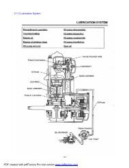
LUBRICATION POINTS<br />
3-6<br />
LUBRICATION<br />
Use general grease
MEMO
FUEL SYSTEM<br />
4-0
4. FUEL SYSTEM<br />
SERVICE INFORMATION ·· 4-1<br />
TROUBLESHOOTING···· 4-2<br />
FUEL TANK········ 4-3<br />
AIR CLEANER CASE···· 4-4<br />
SERVICE INFORMATION<br />
GENERAL SAFETY<br />
4<br />
• Gasoline is extremely flammable. Avoid fire in the work place, also paying particular attention to sparks. Furthermore,<br />
the evaporated (gasified) gasoline is highly explosive. Work in a well-ventilated areas.<br />
• Exhaust gas contains poisonous substance. Do not keep engine running for a long period of time in a closed, or poorly<br />
ventilated area.<br />
STANDARD OF MAINTENANCE<br />
• Fuel tank capacity : 14.85l<br />
• Reserve fuel capacity: 4.0l<br />
• Fuel pump specification : KGF38<br />
Flow quantity : Mimnim 20l/hr<br />
Flow pressure : 380kpa<br />
• Injector specification<br />
Injector angle : 15<br />
Operation pressure : 380kpa<br />
TORQUE VALUE<br />
Air cleaner case cover screw 0.43kgf·m (4.3N·m)<br />
TOOL<br />
Float level gauge<br />
TROUBLESHOOTING<br />
Engine cranks but won’t start<br />
• No fule in tank<br />
• No fule to carburetor<br />
• Cylinder flooded with fuel<br />
• Clogged air cleaner<br />
• No spark at plug<br />
4-1
FUEL SYSTEM<br />
FUEL TANK<br />
FULE TANK<br />
REMOVAL<br />
•Do not smoke or allow flames or sparks in the<br />
work area because gasoline is extremely<br />
flammable. Immediately wipe off a leaked<br />
gasoline.<br />
• Remove the seat.<br />
FUEL TANK SERVE CORD<br />
• Remove the fuel tank cover by looseing the 2<br />
special screws and washer bolt.<br />
• Disconnect the fuel serve cord.<br />
FUEL TUBE<br />
CLIP<br />
• After lift a section of the fuel tank, seperate a clip of the<br />
fuel tank and the hose.<br />
• Remove the fuel tank.<br />
INSTALLATION<br />
• Install the fuel tank in the reverse order of removal.<br />
• After installation, check if there is a gasoline leak.<br />
FUEL FILLER CAP<br />
FUEL TANK COVER<br />
FUEL TANK SEALING RUBBER<br />
FUEL PUMP<br />
FUEL CAP NECK<br />
FUEL TANK<br />
4-2
FUEL SYSTEM<br />
AIR CLEANER CASE<br />
AIR CLEANER CASE<br />
REMOVAL<br />
• Remove the main seat.<br />
• Remove the fuel tank.<br />
• Remove the RH. LH. side covers.<br />
• Remove the fuel tank rear stay.<br />
FUEL TANK REAR STAY<br />
• Remove the battery.<br />
• Remove the battery box by loosening the washer<br />
bolt.<br />
• Remove the air cleaner connecting tube band.<br />
• Remove the air cleaner case mounting bolts, then<br />
remove the air cleaner case.<br />
INSTALLATION<br />
• Install in the reverse order of removal.<br />
•Insert the hook area of battery box into the front<br />
hole of rear fender accurately when assemble the<br />
air cleaner case.<br />
AIR CLEANER ELEMENT<br />
AIR CLEANER CASE COVER<br />
AIR CLEANER CASE<br />
4-3
MEMO
EMS(Engine Management System)<br />
5. EMS(Engine Management System)<br />
1. CAUTION WHEN REPAIRING THE EMS PARTS 5-2<br />
2. THE COMPONENT PARTS OF THE EMS 5-3<br />
3. TERMINAL ARRANGEMENT OF THE ECU 5-4<br />
4. WIRING DIAGRAM OF THE ECU 5-5<br />
5. AN ERROR CHECK LIST FOR EACH TERMINAL OF ECU 5-5<br />
6. SELF-DIAGNOSTIC FUNCTION BY MIL(Malfunction Indicator Lamp) 5-5<br />
- SELF DIAGNOSTIC FUNCTION 5-5<br />
<br />
- FAIL SAFE FUNCTION 5-6<br />
- HOW TO CHECK THE FAULT CODE 5-8<br />
- HOW TO SHOW THE FAULT CODE 5-9<br />
- HOW TO READ THE FAULT CODE 5-9<br />
- FAULT CODE TABLE 5-10<br />
- HOW TO REMOVE THE FAULT CODE 5-11<br />
- EMS TROUBLE SHOOTING 5-11<br />
7. ECU (Electronic control unit) 5-12<br />
8. THROTTLE BODY 5-13<br />
9. INJECTOR 5-17<br />
10. MAPAT 5-20<br />
11. TPS (Throttle Position Sensor) 5-24<br />
12. ETS (Engine Temperature Sensor) 5-27<br />
13. ISA (Idle Speed Actuator) 5-30<br />
14. O2 (Oxgen Sensor) 5-33<br />
15. CHECKING OF ESS CIRCUIT 5-36<br />
16. CHECKING OF MIL CIRCUIT 5-37<br />
17. CKP (Crank Position Sensor) 5-38<br />
18. FUEL PUMP 5-42<br />
19. HOW TO USE SCAN 5-45<br />
- ECU INITIALIZING 5-45<br />
- ISA PWM ADJUSTING 5-47<br />
- IGNITION TIMING CHECK 5-48<br />
- ENGINE RPM CHECK 5-49<br />
5-1
EMS(Engine Management System)<br />
1.CAUTION WHEN REPAIRING THE EMS PARTS.<br />
•If the fuse is short-circuited, find out the cause and repair, replace with the fuse having the specified capacity.<br />
•Do not use the electlic wires or others instead of the fuse.<br />
•Do not drop or throw the EMS parts, because these parts may be damaged by the impact of the drop.<br />
•Do not touch the ECU terminal, because it may be damaged by the static.<br />
•The ignition key off before assembly and disassembly of the ECU coupler.<br />
Otherwise, it might be damage to ECU.<br />
•Do not connect adversely the polarity of battery, otherwise, it might be broken the EMS parts<br />
•While engine operating, do not disassemble the battery terminal.<br />
Otherwise, it might cause damaged the EMS parts.<br />
•Use the specified voltmeter and resistance meter.<br />
5-2
2.THE COMPONENT PARTS OF THE EMS<br />
EMS(Engine Management System)<br />
EMS CONSISTS OF INTAKE AND FULE, IGNITION AND CONTROL SYSTEM.<br />
1) INTAKE SYSTEM<br />
As a system which controls and measures air to be necessary for combustion in engine, the intake system<br />
is composed of pressure sensor of intake parts, intake on sensor, throttle position sensor, throttle body, air<br />
cleaner and ISA(Idle Speed Actuator), etc.<br />
In idling, because throttle value is almost closed, the idle status of engine shall be controlled by means<br />
that idle speed control system is installed in order to control small of quantity of air being necessary for<br />
combustion.<br />
2) FUEL SYSTEM<br />
As a system to supply required fuel for consumption in engine combustion chamber from fuel tank to<br />
injector, this Fuel system is composed of fuel tank, fuel pump, fuel filter, fuel pressure regulator, division<br />
pipe and injector.<br />
The fuel in tank, being high pressed by fuel pump, moves to the division pipe through fuel filter.<br />
Next the fuel is supplied to injector being highly maintained as regulated pressure about the pressure of<br />
intake system.<br />
Injector sprays fuel into the intake system by injection signals of ECU.<br />
3) IGNITION SYSTEM<br />
The ignition system is composed of spark plug which makes ignition spark, a spark timing control part to<br />
control proper spark time in cylinder, high-voltage system, and so forth.<br />
4) CONTROL SYSTEM<br />
Various sensors to move electric signals converted by checking the current engine status<br />
Input interface which works various processes like regulating voltage levels, removal of noise, A/D<br />
conversion, amplifying of inputted signals from above sensors.<br />
Micro-computer which decides output value through various calculating, arithmetic and logic<br />
processing.<br />
Output interface to amplify the above output signals.<br />
Actuator being mechanically worked by receiving the amplified output signals.<br />
(Intake pressure sensor+Intake<br />
temperature)<br />
5-3
EMS(Engine Management System)<br />
3. TERMINAL ARRANGEMENT OF THE ECU<br />
FUNCTION<br />
ECU Earth<br />
Oxygen sensor Earth<br />
Intake pressure sensor Earth<br />
TPS. ETS Earth<br />
Engine KILL<br />
-<br />
-<br />
-<br />
ECU Earth<br />
After main key turn on, Battery power<br />
-<br />
Oxygen sensor Signal<br />
Side stand Signal<br />
-<br />
-<br />
-<br />
Battery Power supply<br />
TPS Power (5V) supply<br />
Throttle Position Sensor Signal<br />
Engine Temperature Sensor Signal<br />
ECU PIN NO. VS FUNCTION<br />
PIN NO. PIN NO. FUNCTION<br />
Remarks<br />
•ECU PIN NO. 6,7,8,11,14,15,16,36 were not connected.<br />
•Terminal arrangement is based on the ECU.<br />
Third Gear<br />
Crank Position Signal B<br />
Communication LOW<br />
MIL<br />
Battery Power<br />
Intake pressure sensor power(5V)<br />
Intake pressure sensor Signal<br />
Intake temperature sensor Signal<br />
Neutral Gear<br />
Crank Position Signal A<br />
Communication HIGH<br />
Engine Speed Signal<br />
Idle Speed Actuator<br />
Oxygen sensor Heat<br />
Ignition coil Earth<br />
-<br />
Ignition Signal<br />
HEad lamp relay Signal<br />
Fuel pump relay Signal<br />
Injector Signal<br />
5-4
EMS(Engine Management System)<br />
4. WIRING DIAGRAM OF THE ECU<br />
5. AN ERROR CHECKLIST FOR EACH TERMINAL OF ECU<br />
PIN NO.<br />
Starting<br />
Idle RPM<br />
Stability<br />
ERROR Checklist<br />
Driving<br />
Durability<br />
SCAN tool<br />
communication<br />
MIL<br />
PIN NO.<br />
Starting<br />
Idle RPM<br />
Stability<br />
ERROR Checklist<br />
Driving<br />
Durability<br />
SCAN tool<br />
communication<br />
MIL<br />
ECU 01<br />
ECU 02<br />
ECU 03<br />
ECU 04<br />
ECU 05<br />
6, 7, 8<br />
ECU 09<br />
ECU 10<br />
ECU 11<br />
ECU 12<br />
ECU 13<br />
14,15,16<br />
ECU 17<br />
ECU 18<br />
ECU 19<br />
ECU 20<br />
ECU 21<br />
ECU 22<br />
O<br />
O<br />
O<br />
O<br />
X<br />
-<br />
O<br />
X<br />
-<br />
O<br />
X<br />
-<br />
X<br />
O<br />
O<br />
O<br />
O<br />
X<br />
O<br />
X<br />
X<br />
X<br />
-<br />
-<br />
O<br />
-<br />
-<br />
X<br />
-<br />
-<br />
-<br />
X<br />
X<br />
X<br />
O<br />
-<br />
O<br />
O<br />
O<br />
O<br />
X<br />
-<br />
O<br />
X<br />
-<br />
O<br />
X<br />
-<br />
X<br />
O<br />
O<br />
O<br />
O<br />
X<br />
X<br />
X<br />
X<br />
X<br />
-<br />
-<br />
X<br />
-<br />
-<br />
X<br />
-<br />
-<br />
-<br />
X<br />
X<br />
X<br />
O<br />
-<br />
O<br />
O<br />
O<br />
O<br />
O<br />
-<br />
O<br />
X<br />
-<br />
O<br />
O<br />
-<br />
X<br />
O<br />
O<br />
O<br />
O<br />
O<br />
X<br />
O<br />
O<br />
O<br />
X<br />
-<br />
X<br />
X<br />
-<br />
O<br />
X<br />
-<br />
X<br />
O<br />
O<br />
O<br />
X<br />
X<br />
ECU 23<br />
ECU 24<br />
ECU 25<br />
ECU 26<br />
ECU 27<br />
ECU 28<br />
ECU 29<br />
ECU 30<br />
ECU 31<br />
ECU 32<br />
ECU 33<br />
ECU 34<br />
ECU 35<br />
ECU 36<br />
ECU 37<br />
ECU 38<br />
ECU 39<br />
ECU 40<br />
O<br />
-<br />
X<br />
O<br />
O<br />
O<br />
X<br />
X<br />
O<br />
O<br />
O<br />
O<br />
X<br />
-<br />
X<br />
O<br />
X<br />
X<br />
O<br />
-<br />
-<br />
X<br />
X<br />
X<br />
-<br />
-<br />
O<br />
O<br />
X<br />
X<br />
-<br />
-<br />
-<br />
O<br />
-<br />
-<br />
O<br />
-<br />
X<br />
O<br />
O<br />
O<br />
X<br />
X<br />
O<br />
O<br />
O<br />
O<br />
X<br />
-<br />
X<br />
O<br />
X<br />
X<br />
O<br />
-<br />
-<br />
X<br />
X<br />
X<br />
-<br />
-<br />
O<br />
O<br />
O<br />
X<br />
-<br />
-<br />
-<br />
O<br />
-<br />
-<br />
X<br />
O<br />
X<br />
O<br />
O<br />
O<br />
O<br />
O<br />
X<br />
O<br />
O<br />
O<br />
O<br />
-<br />
O<br />
O<br />
O<br />
O<br />
X<br />
X<br />
X<br />
O<br />
O<br />
O<br />
X<br />
X<br />
X<br />
O<br />
O<br />
O<br />
X<br />
-<br />
X<br />
O<br />
O<br />
O<br />
5-5
EMS(Engine Management System)<br />
6. SELF-DIAGNOSTIC FUNCTION BY MIL (Malfunction Indicator Lamp)<br />
SELF-DIAGNOSTIC FUNCTION<br />
The EMS is equipped with self-diagnostic function in order to ensure that the engine control system is operation<br />
normally. If this function detects a malfunction in the system, it immediately operates and illuminates the MIL<br />
(malfunction indicator lamp). It gives the rider that malfunction has occurred in the system.<br />
However, the ECU takes fail-safe function, it enables to drive only temporary when that happen.<br />
Normally, the MIL illuminates for 3 seconds, when the main key is turned on.<br />
MIL(Malfuction Indicator Lamp)<br />
when the ignition key ON.<br />
MIL<br />
OFF<br />
ON<br />
Able to engine start<br />
Starting and driving are temporary<br />
Unable to engine start<br />
Remarks 1<br />
If the EMS has some problem and the MIL on and off, engine starting and driving are temporary by the EMS’s<br />
fail safe function. But the EMS is not normal condition, so check the vehicle and repair soonest.<br />
Remarks 2<br />
It might not be able to starting and driving when following problems happen.<br />
- Crankposition sensor<br />
- Injector<br />
- Fuel pump<br />
The MIL on and blink(when this function detects a malfunction in the system)<br />
MIL<br />
ON<br />
Blink<br />
MIL on continuously, when the engine operating<br />
MIL blinks, when the main key is turn on (engine is stop)<br />
5-6
EMS(Engine Management System)<br />
FAIL-SAFE FUNCTION<br />
If the ECU checks something wrong , the vehicle can be driven by its fail safe function.<br />
However, if there are something wrong in fuel pump, injector, crank position sensor, the engine operation<br />
can be impossible.<br />
MIL<br />
INTAKE<br />
INTAKE<br />
on<br />
: : MIL off on/off<br />
: MIL : MIL on on<br />
If there is something wrong in the EMS, it has fail safe function in order for engine to<br />
work and to cover a minimum driving of vehicle.<br />
INTAKE<br />
INTAKE<br />
The value of intake pressure is fixed as the<br />
pressure just before when the intake pressure<br />
sensor is out of order.<br />
The value valve of intake temperature is is fixed as toa<br />
temperature 20.25 when just the before intake when pressure the sensor intake is out<br />
pressure of order. sensor is out of order.<br />
! CAUTION<br />
If the MIL on and blink, starting and driving are temporary by fail safe<br />
function, but, because the conditions of engine operation are not perfect, this can be used in an urgent case.<br />
In this case, safe repairing of vehicle shall be required.<br />
5-7
EMS(Engine Management System)<br />
HOW TO CHECK THE FAULT CODE<br />
There are two methods of checking the fault codes.<br />
Use the MIL in the speedometer and the diagnostic tool.<br />
First) Use the MIL in the Speedometer for checking.<br />
• Turn off the ignition key<br />
• The MIL blinks continuously<br />
• Find the defects by checking the number of lighting, the fault code can be verified (refer to the fault code<br />
table)<br />
Second) The diagnostic tool (refer to scan user’s <strong>manual</strong> for checking.)<br />
• Turn off the ignition key<br />
• Aassemble the coupler of diagnostic tool with the coupler to check the malfunction of vehicle.<br />
• Turn on the ignition key<br />
• Press the power button of diagnostic tool<br />
• Checks according to diagnostic procedure of diagnostic tool.<br />
Third) Use the wireharness for checking<br />
Coupler to check the malfunction diagnosis<br />
Wire color to check the malfunction diagnosis<br />
-P/W : PINK/WHITE : CAN_L<br />
-P/Y : PINK/YELLOW : CAN_H<br />
-B : BLACK : IGNITION KEY<br />
-G : GREEN : GROUND<br />
<br />
<br />
Coupler for checking (ECU 1 - ECU 20 PIN)<br />
Coupler for checking (ECU 21 - ECU 40 PIN)<br />
Measure the wire harness for checking by connecting the ECU with main wire harness to check the ECU.<br />
It has two coupler to check the terminal.<br />
The wireharness to check the ECU arrangement<br />
Coupler for checking : ECU PIN no. 1,2,3,4,5,9,10,12,17,18,19,20 were connected.<br />
ECU PIN no. 6,7,8,11,13,14,15,16 is not connected.<br />
Coupler for checking : ECU PIN no. 21,22,23,24,25,26,27,28,29,30,31,32,33,34,35,37,39,40 were connected.<br />
ECU PIN no. 36 is not connected.<br />
5-8
EMS(Engine Management System)<br />
HOW TO SHOW THE FAULT CODE<br />
There are two methods to show the Fault codes.<br />
First) The methods to show in engine operation<br />
In engine operation, when there is something wrong in each part of EMS, the MIL keeps light on without the<br />
light on/off function of MIL in order for driver to acknowledge defect. This time, so for checking the fault code,<br />
stop the vehicle and engine, and in the ignition key on, by checking the number of lighting, the fault code can be<br />
verified.(refer to the fault code table)<br />
Second) The ways of indication only turn on the ignition key.<br />
When only ignition key is on and if the defect of each part brings out, the MIL keeps showing<br />
the Fault code of defect part repeatedly in order to give defect information to driver.<br />
!<br />
CAUTION<br />
If the MIL on when engine is working, engine is able to be operated by fail safe. However, in the event that<br />
Injector, Fuel pump, Ignition coil has something wrong, vehicle may not been driven and engine not started.<br />
HOW TO READ THE FAULT CODE<br />
The fault codes are showed as 2 digits on the MIL of EMS.<br />
Only one defect code is showed up to prior sequence of defects. This time, that fault code is repeatedly showed.<br />
E.g. ) The Fault code of ISA<br />
ON<br />
OFF<br />
1.5 sec 3 sec<br />
1 flashing cycle : 0.5 sec<br />
If many problems will happened in the EMS parts at the same time, only one fault code is displayed by the<br />
priority, however, the ECU remembers all the fault codes.<br />
After revise the code, remove the memorized fault code by the method of warm up.(5-10)<br />
(Refer to remove the fault codes)<br />
When the vehicle is checked using the diagnosis tool.<br />
- If the vehicle is check using the malfunction diagnosis tool, all fault code check is possible.<br />
5-9
EMS(Engine Management System)<br />
FAULT CODES TABLE<br />
MIL INDICATION<br />
(The number of blinks)<br />
Fault<br />
code no.<br />
Priority<br />
order<br />
Description<br />
No failure<br />
Crank position sensor failure(CKP)<br />
Injection valve failure(IV)<br />
Idle speed actuator failure (ISA)<br />
Electrical fuel pump failure (EFP)<br />
Intake Manifold absolute pressure signal<br />
failure (IMP)<br />
Throttle position signal failure (TPS)<br />
O2 sensor heater output failure (LSH)<br />
Lambda signal failure (VLS)<br />
Engine temperature signal failure (TENG)<br />
Breathing air temperature signal failure<br />
(TBA)<br />
Engine speed signal output failure (ESS)<br />
Headlamp relay failure<br />
Malfunction indicate lamp failure (MIL)<br />
5-10
EMS(Engine Management System)<br />
HOW TO REMOVE THE FAULT CODE<br />
Remove the fault codes in two ways;<br />
First) Full warm up<br />
1. Starting the engine.<br />
- The MIL blinks continuously because the ECU memorized the fault code yet.<br />
2. Full warm up the engine (keep idling five minutes)<br />
3. Turn off the ignition key after full warm up the engine<br />
4. Turn on the ignition key again, and check whether the fault code is disappeared or not.<br />
After full warm up, it is possible to check the fault code is removed with the ignition key on/off.<br />
If many problems happened in the EMS parts at the same time, only one defect code will is displayed<br />
by the priority order.<br />
Even thought repair a fault and remove the memorized fault code, another fault code blinks.<br />
at this time, revise the fault and remove the memorized fault code by the warm up.<br />
Second) Malfunction diagnosis tool<br />
(refer to the scan user’s <strong>manual</strong>)<br />
EMS TROUBLE SHOOTING<br />
Inspection before diagnosis<br />
Inspection the following before malfunction diagnosis.<br />
Quantity of engine oil and leakage<br />
Quantity of fuel and leakage<br />
Blocked of air cleaner<br />
Condition of battery<br />
Free play of throttle cable<br />
Cutting of fuse<br />
Leakage of emission gas<br />
Connection of each coupler<br />
Cylinder press pressure<br />
Condition of spark plug<br />
5-11
EMS(Engine Management System)<br />
SEAT<br />
SEAT LOCK<br />
7.ECU(ELECTRONIC CONTROL UNIT)<br />
It is located inside a pillion seat<br />
! CAUTION<br />
The key is off before disassembly.<br />
Remove the setting grommet and center cover.<br />
CENTER COVER<br />
COVER SETTING GROMMET<br />
ECU GROUND WIRE<br />
Remove<br />
ECU coupler<br />
Remove the coupler in sequence<br />
Remove the 4 flange bolts securing ECU<br />
<br />
FLANGE BOLTS<br />
<br />
Install<br />
Install in the reverse order of removal<br />
! CAUTION<br />
Be sure to assemble the ECU ground wire.<br />
(The color is green)<br />
5-12
EMS(Engine Management System)<br />
8. THROTTLE BODY<br />
Remove the seat support pipe.<br />
Remove the fuel tank.<br />
Loosen the screw securing air cleaner<br />
connecting tube band.<br />
Remove the throttle body and air cleaner.<br />
AIR CLEANER<br />
MAPAT SENSOR<br />
Remove the gasoline in fuel tube.<br />
Disconnect fuel tube securing inject or cap.<br />
Disconnect injector, MAPAT, throttle sensor,<br />
ISA coupler.<br />
Disconnect throttle cable.<br />
INJECTOR<br />
INSULATOR<br />
Loosen the 2 flange bolts securing insulator<br />
and remove the throttle body assy.<br />
5-13
EMS(Engine Management System)<br />
INJECTOR<br />
THROTTLE BODY<br />
DISCONNECT THE THROTTLE BODY<br />
Remove the each component parts securing<br />
throttle body and check.<br />
INSULATOR<br />
MAPAT SENSOR<br />
△! CAUTION<br />
Do not disconnect both the throttle adjust<br />
screw and adjust nut.<br />
REMOVE<br />
Loosen the throttle body 2 bolts securing the<br />
insulator.<br />
Disconnect the TPS (Throttle position sensor).<br />
Disconnect the ISA(Idle speed actuator).<br />
Disconnect the MAPAT.<br />
IDLE SPEED ACTUATOR<br />
△! CAUTION<br />
Do not disconnect the throttle valve.<br />
THROTTLE SHAFT<br />
CHECKING THE THROTTLE BODY<br />
Checking the O-ring.<br />
Checking the Throttle shaft.<br />
Checking the Throttle valve.<br />
O-RING<br />
Checking the ISA.<br />
Checking the TPS.<br />
△! CAUTION<br />
Replace the O-ring with new one.<br />
O-RING<br />
5-14
EMS(Engine Management System)<br />
INJECTOR<br />
DISASSEMBLE THE INSULATOR<br />
Disconnect injector cap bolt.<br />
MAPAT SENSOR<br />
O-RING<br />
Disconnect injector and injector cap at the<br />
same time from the insulator.<br />
Disconnect injector and injector cap.<br />
MAPAT SENSOR<br />
INSULATOR<br />
INJECTOR<br />
CAP<br />
CHECKING THE INSULATOR<br />
Check the O-ring.<br />
Check the insulator inside.<br />
Check the MAPAT sensor.<br />
Check the injector<br />
Assemble is the reverse order of removal.<br />
△! CAUTION<br />
Replace the o-ring with new one.<br />
MAPAT SENSOR<br />
INJECTOR<br />
THROTTLE BODY<br />
INSULATOR<br />
INSTALLATION OF INSULATOR AND<br />
THROTTLE BODY<br />
Installation of insulator and throttle body in<br />
the reverse order of removal.<br />
Check the o-ring when the insulator assembly.<br />
Torque : 1.0 kgf m<br />
! CAUTION<br />
△<br />
Replace the gasket with new one.<br />
Install the assembled insulator and throttle<br />
body to the cylinder head.<br />
Torque : 1.2 kgf m<br />
5-15
EMS(Engine Management System)<br />
THROTTLE CABLE<br />
ASSEMBLY<br />
Assemble the throttle cable.<br />
Adjust the free play of throttle grip.<br />
INSPECTION OF SENSOR AND<br />
ACTUATOR<br />
Connect each sensor and the actuator coupler.<br />
Check the ISA.<br />
Check the TPS.<br />
Check the MAPAT sensor.<br />
△<br />
! CAUTION<br />
Be sure to the valve of TPS is whether the<br />
standard valve after it became assembly.<br />
ADJUST SCREW<br />
ADJUSTMENT OF IDLE SPEED<br />
ACTUATOR (ISA)<br />
△! CAUTION<br />
The ECU is always initilized, before the engine<br />
is starting.<br />
The vehicle is warms up enough to adjust the<br />
idling speed.<br />
Disconnect the RH. side cover.<br />
Connect the coupler of scanner to the coupler<br />
of diagnostic tool.<br />
Press the POWER button on the scanner and<br />
check the ISA value.<br />
If the ISA value is not around 20% adjust it<br />
using the adjust screw to around 20% in 80~90<br />
of engine temperature.<br />
ADJUST SCREW<br />
5-16
EMS(Engine Management System)<br />
INJECTOR<br />
9.INJECTOR<br />
Remove<br />
• Remove the fuel tank.<br />
! CAUTION<br />
•The key is off before disassembly.<br />
• After push the injector coupler, pulling it<br />
upward.<br />
<br />
<br />
• Remove the injector cap bolt.<br />
! CAUTION<br />
•Be sure to check the engine is cooling because<br />
a little gasoline remains. it could be still hot<br />
and it could be cause fire.<br />
• Be sure to injector the gasoline, after remove<br />
the coupler from the ignition coil.<br />
• It could be damaged for the fire, sparked on the<br />
spark plug.<br />
• Remove the injector.<br />
Assemble<br />
• Install in reverse order of removal.<br />
5-17
EMS(Engine Management System)<br />
CHECKING METHODS BY FAULT CODES<br />
Checking of the Injector circuit<br />
The fault code is displayed by MIL<br />
Checking Circuit<br />
ECU<br />
40 : INJECTOR control<br />
39 : FUEL PUMP control<br />
INJECTOR<br />
FUEL PUMP RELAY<br />
Coupler terminal is based on wire harness.<br />
5-18
EMS(Engine Management System)<br />
CHECKING PROCEDURE<br />
1) Turn off the ignition key.<br />
2) Check to see if the injector coupler has come loose or the wire is peeling off.<br />
If there is no problem, measured the resistance of injector.<br />
3)Disassemble the injector coupler and measure the resistance between injector terminals.<br />
The resistance of injector : 14.5±0.7[ ], 20<br />
Remarks : measuring unit for resistance : resistance ‘ R ‘ [ ]<br />
4)If there is no problem, check the continuity between each terminal and ground.<br />
The resistance between each terminal and ground : ∞[ ]<br />
If resistance value is not normal, replace injector with the new one.<br />
5)If the resistance is normal, turns on the ignition key<br />
- If the fuel pump operated for 3 seconds, the power supply relay of injector is normal.<br />
6) Measure between the voltage of coupler.<br />
Measuring terminal : BLACK/RED electric wire ~ ground<br />
Measuring voltage : battery voltage – 1.0[V]over<br />
Remarks : Measuring unit of voltage : voltage [V]<br />
7) If the measured voltage is normal,<br />
Check the ‘Blue/Yellow’ electric wire to see if they have been broken or have short-circuited<br />
or if the wire-harness coupler and the ECU coupler are a bad contact (ECU terminal No. 40)<br />
If there is no problem in the electric wires, ECU is broken<br />
Replace the ECU with new one, it rechecks<br />
8) If the measured voltage is not normal,<br />
Check the Black/Red electric wire to see if they have been broken or have short-circuited.<br />
Check the fuel pump relay.<br />
9) After fault repaired, to erase the memorized fault code in the ECU is refer to how to remove the fault code(5-11).<br />
5-19
EMS(Engine Management System)<br />
<br />
<br />
MAPAT SENSOR<br />
10. MAPAT(Manifold Air pressure<br />
sensor, Temperature sensor)<br />
It is Located on the left side of the throttle<br />
body.<br />
Remove<br />
Remove the MAPAT sensor coupler.<br />
! CAUTION<br />
The key is off before disassembly.<br />
Loosen the MAPAT sensor screw 2EA.<br />
MAPAT sensor.<br />
Assemble<br />
• Install in reverse order of removal.<br />
5-20
EMS(Engine Management System)<br />
Check the MAPAT Circuit(Intake Pressure Sensor (IMP)+Intake Temperature Sensor(TBA))’s circuit<br />
Fault code number is displayed by MIL<br />
The Fault code of intake pressure sensor<br />
The Fault code of intake temperature sensor<br />
Checking circuit<br />
MAPAT<br />
ECU<br />
3<br />
3<br />
: Intake<br />
: Inhalation<br />
pressure sensor<br />
pressure<br />
ground<br />
26<br />
sensor<br />
: 5V voltage<br />
GROUND<br />
27 26 :: IMP 5V voltage<br />
28 27 :: TBA IMP 28 : TBA<br />
Coupler terminal is based on the side of wire-harness<br />
CHECKING PROCEDURE<br />
1) Turn off the ignition key .<br />
2) Check to see if the MAPAT coupler has come loose or the wire is peeling off.<br />
If there is normal, measured the input 5 voltage of MAPAT’s coupler.<br />
3) Disassemble the coupler of MAPAT and turn on the ignition key<br />
4) Measure the input voltage of MAPAT (intake pressure sensor + intake temperature sensor)’s coupler.<br />
Input voltage : 4.5 ~ 5.5[V]<br />
Measuring terminal : MAPAT 3 terminal ~ MAPAT 1 terminal<br />
Remarks : Measuring unit of voltage : voltage [V]<br />
5) If voltage value is not normal,<br />
Check to see if the ECU coupler is loose or if there is a bad contact.<br />
Check the ‘P’ electric wire, ‘P/G’ electric wire, ‘P/L’ to see if they have been broken short-circuited<br />
Remark : refer to (5-16) if the intake pressure sensor is broken<br />
refer to (5-16) if the intake temperature sensor is broken<br />
After fault repaired, To erase the memorized fault code in the ECU is refer to how to remove the fault code(5-11).<br />
5-21
EMS(Engine Management System)<br />
CHECKING OF THE INTAKE PRESSURE SENSOR<br />
1) If voltage value is normal, turn off the ignition key.<br />
Connect the MAPAT(intake pressure sensor + intake temperature sensor) coupler<br />
2) The wire-harness to check the ECU is connected with the ECU with a wire-harness coupler.<br />
Refer to how to assemble or disassemble the ECU ( 5-32 )<br />
3) Turn on the ignition key. Start engine and operate idle.<br />
4) Measure the voltage of intake pressure sensor for ECU check.<br />
Measuring the voltage of intake pressure sensor.<br />
Measuring terminal : ECU No. 27(P/L:PINK/BLUE) ~ ECU No.3(P/G : PINK/GREEN)<br />
Measuring voltage : 0.1[V] ~ 4.8[V]<br />
Remarks : Measuring unit of voltage : Voltage [V]<br />
The voltage of air pressure;<br />
20[kPa]: 0.719 ~ 0.859[V]<br />
107[kPa]: 4.154 ~ 4.294[V]<br />
5) If the measured voltage is not normal,<br />
Check the ‘P’ electric wire, ‘P/G’ electric wire, ‘P /L’<br />
electric wire to see if they have been broken or have<br />
short- circuited.<br />
Replace the MAPAT sensor with the new one and it rechecks.<br />
Connecting the wire harness for checking<br />
If measuring voltage is normal,<br />
Check the ‘P’ electric wire, ‘P/G’ electric wire, ‘P/L’ electric wire<br />
to see if they have been broken or have short- circuited<br />
if there is a bad contact.<br />
badness of terminal No. 3, No. 26, No.27 of ECU coupler.<br />
If the electric wire is no problem, ECU is broken.<br />
Replace the ECU with the new one, it rechecks.<br />
6) After repaired, refer to the fault code removal method to erase<br />
the memorized fault code in the ECU.<br />
5-22
EMS(Engine Management System)<br />
CHECKING OF INTAKE TEMPERATURE SENSOR<br />
1) If voltage value is normal, turn off ignition key.<br />
2) Disassemble the MAPAT coupler and measure the resistance of intake temperature sensor.<br />
Resistance of intake pressure sensor : 2000±100[Ω], 25±1<br />
Measuring terminal : ECU No. 28(P/B :PINK/BLUE) ~ ECU No. 3(P/G : PINK/GROUND)<br />
Remarks : Measuring value for resistance : Resistance[ ]<br />
The Voltage of air pressure;<br />
24 ~ 26[ ] : 1800~2200[ ]<br />
99 ~ 101[ ] : 161~206[ ]<br />
3) If measuring resistance is not normal,<br />
Replace the MAPAT sensor with new one and it rechecks.<br />
If the measured voltage is normal,<br />
Check the ‘P’ electric wire, ‘P/G’ electric wire, ‘P/L’ electric wire<br />
to see if they have been broken or have short- circuited<br />
if there is a bad contact of terminal No. 3, No. 26, No. 27<br />
of ECU coupler.<br />
If the electric wire is no problem, ECU is broken.<br />
Replace the ECU with the new one, it rechecks.<br />
4) Turn on the ignition key. Start the engine and idling.<br />
5) Measure the voltage of intake pressure sensor for ECU check.<br />
Measuring the voltage of intake pressure sensor<br />
- Measuring terminal: ECU No.28(TBA)<br />
~ ECU No.3(IMP ground)<br />
- Measuring voltage: 0.1[V] ~ 4.9[V]<br />
Remarks : Measuring unit of voltage : Voltage [V]<br />
6) If the measured voltage is not normal,<br />
Check the ‘P’ electric wire, ‘P/G’ electric wire, ‘P /L’<br />
electric wire to see if they have been broken<br />
or have short- circuited.<br />
Replace the MAPAT sensor with new one and it rechecks.<br />
If the measured voltage is normal,<br />
Check the ‘P’ electric wire, ‘P/G’ electric wire, ‘P/L’ electric wire<br />
to see if they have been broken or have<br />
short- circuited if there is a bad contact of terminal<br />
No. 3, No. 26, No.28 of ECU coupler.<br />
If the electric wire is no problem, ECU is broken.<br />
Replace ECU with the new one, it rechecks.<br />
7) After fault repaired, To erase the memorized fault code in<br />
the ECU is refer to how to remove the fault code(5-11).<br />
5-23
EMS(Engine Management System)<br />
<br />
<br />
11.TPS(THROTTLE POSITION SENSOR)<br />
It is located on the left side of throttle body.<br />
Remove<br />
Press the TPS coupler then remove it with<br />
pulling.<br />
! CAUTION<br />
The key is off before disassembly.<br />
Remove the TPS screw 2EA<br />
MAPAT SENSOR<br />
SCREWS<br />
Remove the TPS<br />
Assemble<br />
• Install in reverse order of removal.<br />
5-24
CHECKING THE TPS(Throttle Position Sensor) CIRCUIT DIAGRAM<br />
Fault code number is displayed by MIL<br />
EMS(Engine Management System)<br />
Checking circuit<br />
The coupler terminal is based on the side of wire-harness<br />
Checking Procedure<br />
1) Turn off ignition key .<br />
2) Check the TPS(Throttle Position Sensor) coupler is loose, or bad.<br />
If there is no defect, measure the input voltage of TPS.<br />
3) Disassemble the TPS coupler<br />
4) Turn on the ignition key.<br />
Input voltage : 4.5 ~ 5.5[V]<br />
Measuring terminal : ECU NO.18(Gr/B : GRAY/BLACK) ~ ECU NO.4 (W/R : WHITE/RED)<br />
Measure the terminal voltage of TPS’s coupler.<br />
Measuring voltage : 4.5[V] ~ 5.5[V]<br />
Remarks : Measuring unit of voltage : Voltage [V]<br />
If voltage value is not normal,<br />
Check to see if the ECU coupler is loose if there is bad contact.<br />
Check the ‘GR/B’’ electric wire, ‘W/R’ electric wire, ‘GR /L’ electric wire to see if they have been<br />
broken or have short- circuited.<br />
5) If the value of voltage is normal, turn off the ignition key.<br />
5-25
EMS(Engine Management System)<br />
Checking Procedure<br />
6) Check continuty between the Sensor Ground Terminal of TPS and Earth.<br />
The continuty TPS : 0~1.0[ ],20±1<br />
Measuring Terminal : ECU No. 4 (W/R : WHITE/RED) ~ EARTH<br />
Remarks : Measuring unit for resistance : Resistance ‘ R ‘ [ ]<br />
7) If not problem, measure the resistance of TPS.<br />
By turning round throttle Lever, measure the resistance.<br />
The resistance of TPS<br />
If the throttle is totally closed : 0.9~1.6[k ],20±1<br />
If the throttle is totally opened : 2.3~2.6[k ],20±1<br />
Measuring Terminal : ECU No. 19 (Gr/L: GRAY/BLUE) ~<br />
ECU No.4 (W/R : WHITE/RED)<br />
Remarks : Measuring value of resistance : Resistance[k ]<br />
8) If resistance and the continuty are not abnormal.<br />
Adjust correctly the position of TPS<br />
Replace the TPS with the new one and re-check.<br />
9) If resistance and continuty are normal, connect the coupler of TPS.<br />
10) Turn on the ignition key.<br />
11) Measure the TPS voltage of the wire-harness to check the ECU.<br />
Rotate the throttle lever, measure the voltage<br />
Measuring terminal: ECU No. 19 (Gr/L: GRAY/BLUE) ~<br />
ECU No.4 (W/R : WHITE/RED)<br />
Output voltage of TPS<br />
-If the throttle is totally closed : 0.1~0.6[V]<br />
-If the throttle is totally opened : 4.0~5.5 [V]<br />
Remarks : Measuring unit for voltage : Voltage [V]<br />
12) If the measured voltage is abnormal,<br />
Replace the TPS with the new one, and re-check.<br />
If the measured voltage is normal,<br />
Check the ‘GR/B’ electric wire, ‘GR/L’ electric wire, ‘W/R’ electric wire<br />
to see if they have been broken or have short- circuited if there<br />
is a bad contact of terminal No. 4, No. 18, No. 19 of ECU coupler.<br />
If there is no problem in wires, ECU has broken down.<br />
Replace ECU with the new one, and recheck.<br />
13) After fault repaired, To erase the memorized fault code in the ECU is refer<br />
to how to remove the fault code(5-11).<br />
5-26
EMS(Engine Management System)<br />
THERMO STAT<br />
12.ETS(ENGINE TEMPERATURE SENSOR)<br />
It is located on the left-hand side of cylinder<br />
head.<br />
ENG. TEMP.<br />
SENSOR<br />
Remove<br />
After pressing the ETS coupler and pull it..<br />
! CAUTION<br />
The key is off, before disassembly.<br />
Remove the ETS coupler.<br />
<br />
<br />
ENG. TEMP.<br />
SENSOR<br />
Remove the ETS.<br />
Assemble<br />
Install in reverse order of removal.<br />
5-27
EMS(Engine Management System)<br />
1)CHECKING THE CIRCUIT DIAGRAM OF ETS(Engine Temperature Sensor)<br />
Fault code number is displayed by MIL<br />
CHECKING CIRCUIT<br />
ETS<br />
ECU<br />
4 : SENSOR GROUND<br />
20 : ETS 50V SUPPLY VOLTAGE<br />
Coupler terminal is based on the side of wire-harness<br />
Checking Procedure<br />
1) Turn off the ignition key .<br />
2) Check to see if the ETS(Throttle Position Sensor) coupler is loose, or bad.<br />
If there is no defect, measure the input voltage of ETS.<br />
3) Disassemble the coupler of ETS<br />
4) Turn on ignition key.<br />
Measuring terminal : ECU No. 20 (Gr/L: GREEN/BLUE)<br />
~ ECU No.4 (W/R : WHITE/RED)<br />
ETS<br />
Measure the terminal voltage of ETS’s coupler.<br />
Measuring voltage : 4.5[V] ~ 5.5[V]<br />
Remarks : Measuring unit for voltage : voltage [V]<br />
If the voltage value is not normal,<br />
Check to see if the ECU coupler is loose, or bad contact.<br />
Check the ‘G/L’’ electric wire, ‘W/R’ electric wire, ‘W/R’ electric wire to see if they have been<br />
broken or have short- circuited.<br />
5) If the voltage value is normal, turn off the ignition key.<br />
6) Disassemble the coupler of ETS, and measure the resistance of ETS.<br />
Resistance of ETS :1.6[k ]~10.6[k ],20 ~80<br />
Measuring terminal : Each terminal of ETS<br />
Remarks : Measuring unit for resistance : Resistance ‘ R ‘ [k ]<br />
5-28
EMS(Engine Management System)<br />
6-1) If the measured value is not normal,<br />
Replace the ETS with the new one, recheck.<br />
If the measured value is normal,<br />
Check the G/L electric wire, W/R electric wire to see if they have been broken or have short-circuited or if<br />
the ECU coupler is a bad contact ( No.4, No. 20.)<br />
If the electric wire is no problem, ECU is broken.<br />
Replace ECU with the new one, recheck.<br />
6-2) After fault repaired, To erase the memorized fault code in the ECU is refer to how to remove the fault code(5-10).<br />
Checking Procedure<br />
1) Disassembly<br />
Disassemble the ETS(Engine Temperature Sensor) : (Refer to 5-27)<br />
2) Check the ETS(Engine Temperature Sensor)<br />
Connect two terminals of ETS to the probe of the tester and insert even its screw point of ETS into oil.<br />
Read the temperature of thermometer depending upon oil temperature’s change and tester’s value.<br />
Characters of ETS<br />
Temperature<br />
20<br />
80<br />
Resistance value<br />
10.6[k ]~14.4[k ]<br />
1.35[k ]~1.65[k ]<br />
110<br />
Measuring unit of resistance : Resistance ‘ R ‘[k ]<br />
0.57[k ]~0.69[k ]<br />
If the value of resistance is high or out of the standard value, replace the ETS with the new one.<br />
!<br />
CAUTION<br />
1)Be careful do not fell down the ETS, because its weakness.<br />
2)Be careful the ETS and the Thermometer do not to touched to oil bowl.<br />
3)Be careful oil temperature will not raised more than measurement temperature.<br />
3) Install<br />
Install in the reverse order of removal with standard torque.<br />
ETS torque : 3.0[kgf m]<br />
5-29
EMS(Engine Management System)<br />
13.ISA(IDLE SPEED ACTUATOR)<br />
<br />
Remove<br />
Remove the ISA coupler<br />
! CAUTION<br />
<br />
The key is off, before disassembly.<br />
Remove the injector cap firstly for<br />
dismantling the ISA.<br />
Remove the ISA screws. (2EA)<br />
Remove the ISA.<br />
Assemble<br />
Install in reverse order of removal.<br />
5-30
EMS(Engine Management System)<br />
1)CHECK THE ISA(IDEL SPEED ACTUATOR) CIRCUIT.<br />
Showing of defects codes by MIL<br />
CHECKING CIRCUIT<br />
40<br />
ECU<br />
39<br />
33 39 :: ISA FUEL CONTROL PUMP CONTROL<br />
39:FUEL 40 : INJECTOR PUMP CONTROL<br />
ISA<br />
FUEL PUMP RELAY<br />
Coupler terminal is based on the side of the wire-harness<br />
CHECK PROCEDURE<br />
1) Turn off ignition key .<br />
2) Check to see if the ISA(Throttle Position Sensor) coupler is loose,<br />
or bad.If there is no defect, measure the input voltage of ISA<br />
3) Disassemble the coupler of ISA, measure the resistance<br />
between ISA terminals.<br />
ISA resistance : 31.5~ 38.5[ ],20<br />
remarks : Measuring unit of resistance : Resistance ‘R’[ ]<br />
4) If there is no problem, check about the level of electricity flow between each terminal,<br />
and between each ground.<br />
Resistance between each terminal , and between each ground : ∞[ ]<br />
If measure resistance value is not normal, replace with the new one<br />
Disassembly and Assembly : refer to ( 5-28 )<br />
remarks : Measuring unit for resistance : Resistance ‘R’[ ]<br />
5-31
EMS(Engine Management System)<br />
CHECK PROCEDURE<br />
5) If the measured resistance and continuty is abnormal.<br />
Replace ISA with the new one, and recheck.<br />
6) If resistance and continuty is normal, connect the coupler of ISA.<br />
7) Turn on ignition key<br />
8) Measure ISA voltage of wire-harness to check ECU.<br />
Measuring terminal : B/R electric wire ~ EARTH<br />
Output voltage of ISA : BATTERY VOLTAGE[V]<br />
Remarks : Voltage measuring unit : Voltage [V]<br />
If the measured voltage is normal,<br />
Check the ‘B/R’ electric wire, ‘L/G’ electric wire, ‘W/R’ electric wire to see if they have been broken or<br />
have short- circuited if there is a bad contact of terminal No. 33, No. 39 of ECU coupler.<br />
If there is no problem in wires, ECU has broken down.<br />
Replace ECU with the new one, recheck.<br />
If the measured voltage is abnormal,<br />
Check the ‘B/R’’ electric wire, ‘L/G’ electric wire, ‘W/B’ electric wire to see if they have been<br />
broken or have short- circuited.<br />
9) After fault repaired, To erase the memorized fault code in the ECU is refer to how to remove the fault code(5-11)<br />
5-32
EMS(Engine Management System)<br />
14.O2(Oxygen) SENSOR<br />
It is located on the exhaust pipe<br />
! CAUTION<br />
O2 SENSOR COUPLER<br />
The key is off before disassembly.<br />
O2 SENSOR<br />
Remove<br />
Center cowl<br />
O2 sensor coupler<br />
O2 SENSOR<br />
O2 SENSOR COUPLER<br />
Check the O2 sensor.<br />
Handle with care or fraglile.<br />
O2 SENSOR<br />
Assemble<br />
Install in reverse order of removal.<br />
5-33
EMS(Engine Management System)<br />
1) CHECKING OF OXYGEN(O2) SENSOR CIRCUIT<br />
Fault code number is displayed by MIL<br />
Fault code number is displayed by MIL of the oxygen(O2)sensor lambda signal.<br />
CHECKING CIRCUIT<br />
OXYGEN SENSOR<br />
ECU<br />
2 : LAMBDA SENSOR GROUND<br />
12 : OXYGEN SENSOR SIGNAL<br />
34 : OXYGEN SENSOR HEATER<br />
Coupler terminal is based on the side of Wire-Harness.<br />
CHECKING FOR A FAULT CODE BY OXYGEN(O2)SENSOR HEATER<br />
1) Turn off the ignition key.<br />
2) Check the O2(oxygen) coupler is loose, or bad.<br />
If there is no defect, measure the input voltage of O2(oxygen)<br />
3) Disassemble the coupler of oxygen(O2)sensor and turn on ignition key<br />
4) Measure input voltage of oxygen(O2)sensor coupler<br />
Input voltage : Battery voltage[V]<br />
Measuring terminal (side of Wire-harness) : oxygen(O2)3 terminal of sensor coupler<br />
(B/BR : BLACK/BROWN) ~ EARTH<br />
Remarks : Measuring unit of voltage : Voltage[V]<br />
5-34
CHECKING FOR A FAULT CODE BY OXYGEN(O2)SENSOR HEATER<br />
If the voltage value is abnormal,<br />
Check to see if the ECU coupler is loose or if there is bad contact.<br />
Check the ‘B/B’’ electric wire, ‘G/W’ electric wire to see if they have been<br />
broken or have short- circuited.<br />
EMS(Engine Management System)<br />
5) If the voltage value is normal, turn off the ignition key.<br />
Measure the Resistance of oxygen (O2) Sensor heater : about 9[ ], about 22<br />
Measuring terminal (side of wire-harness) : oxygen(O2)4 terminal of sensor coupler<br />
(B/BR : BLACK/BROWN) ~ ECU No.34(G/W :GREEN/WHITE)<br />
Remarks : Measuring unit of Resistance : Resistance ‘R’[ ]<br />
6) If the measured resistance is abnormal,<br />
Replace the oxygen(O2)sensor with new one and recheck it.<br />
If the measured resistance is normal,<br />
Check the ‘B/B’’ electric wire, ‘G/W’ electric wire to see if they have been<br />
broken or have short- circuited.<br />
If the electric wire is no problem, the ECU is broken.<br />
Replace the ECU with new one, and recheck it.<br />
CHECKING FOR A FAULT CODE BY OXYGEN(O2)SENSOR LAMBDA SIGNAL<br />
1) Turn off the ignition key<br />
2) Check the O2(oxygen) coupler is loose, or bad.<br />
If there is no defect, measure the input voltage of O2(oxygen)<br />
3) The wire-harness to checck the ECU is connected to the ECU with a coupler.<br />
refer to the ECU assembly/disassembly.<br />
4) Turn on the ignition key<br />
5) Measure the oxygen(O2)sensor voltage of wire harness to check ECU.<br />
Measuring terminal: ECU No.12(V :VIOLET)~ ECU No.2(V/B:VIOLET/BLACK)<br />
Output voltage of oxygen(O2) sensor : 0.1~0.8[V]<br />
Remark : Measuring unit of voltage : Voltage[V]<br />
Assembly of oxygen(O2)sensor : 4.08 ~ 6.12[kgf<br />
If the measured voltage is normal,<br />
Check the ‘B/R’ electric wire, ‘V’ electric wire, ‘V/B’ electric wire to see if they have been broken or<br />
have short- circuited if there is a bad contact of terminal No. 2, No. 12 of ECU coupler.<br />
If there is no problem in wires, ECU is broken.<br />
Replace the ECU with new one, and recheck it.<br />
If the measured voltage is abnormal,<br />
Check the ‘V’ electric wire, ‘V/B’ electric wire, ‘W/B’ electric wire to see if they have been<br />
broken or have short- circuited.<br />
6) After fault repaired, To erase the memorized fault code in the ECU is refer to how to remove the fault code(5-11)<br />
5-35
EMS(Engine Management System)<br />
15.CHECKING OF ENGINE SPEED SIGNAL(ESS)CIRCUIT<br />
Fault code number is displayed by MIL<br />
CHECKING CIRCUIT<br />
TACHOMETER<br />
ECU<br />
32 : ESS(ENGINE SPEED SIGNAL)<br />
Coupler terminal is based on the side of Wire-Harness.<br />
CHECK PROCEDURE<br />
1) Turn off the ignition key .<br />
2) Check the ESS coupler is loose, or bad.<br />
If there is no problem, check the resistance of tachometer.<br />
3) Check the resistance between each terminals and ground.<br />
Measuring terminal: B electric wire ~ EARTH,<br />
ECU NO. 32 (B/Y:BLACK/YELLOW) ~ EARTH<br />
The resistance between each terminals and ground : ∞[ ]<br />
If the measured resistance value is abnormal, replace the part with new one.<br />
Refer to ( ) for assembly and disassembly<br />
Remark : Measuring unit of voltage : Resistance [ ]<br />
4) If the measured resistance and continuity are abnormal,<br />
. Replace the tachometer with new one, and it rechecks.<br />
5) If the resistance and continuity are normal, contact the tachometer coupler.<br />
6)Turn on the ignition key.<br />
7) Measure the voltage or tachometer of wire harness for ECU check.<br />
Measuring terminal: B electric wire ~ G electric wire => Output Voltage: battery voltage<br />
Measuring terminal: ECU No. 32(B/Y: BLACK/YELLOW) ~ G electric wire =>Output voltage: 9[V]~15[V]<br />
Measuring terminal: ECU No. 32(B/Y: BLACK/YELLOW) ~ G Measuring the output voltage of<br />
electric wire, using the PVA(peak voltage adapter) multi-tester tool.<br />
Remark : Measuring unit of voltage : Voltage[V]<br />
If the measured voltage is normal,<br />
Check the ‘B/Y’ electric wire, ‘B’ electric wire, ‘G’ electric wire to see<br />
if they have been broken or have short- circuited if there is a bad<br />
contact of terminal No. 32 of ECU coupler.<br />
If there is no problem in wires, ECU has is broken.<br />
Replace the ECU with new one, and recheck it.<br />
If the measured voltage is abnormal,<br />
Check the ‘B/Y’ electric wire, ‘B’ electric wire, ‘G’ electric wire to see if they have been<br />
broken or have short- circuited.<br />
8) After fault repaired, To erase the memorized fault code in the ECU is refer to how to remove the fault code(5-11)<br />
5-36
EMS(Engine Management System)<br />
16.CHECKING OF MIL(MALFUNCTION INDICATOR LAMP)CIRCUIT<br />
Fault code number is displayed by MIL<br />
CHECKING CIRCUIT<br />
ECU<br />
24 : MALFUNCTION INDICATOR LAMP OUTPUT<br />
MALFUNCTION INDICATOR LAMP(MIL)<br />
CHECK PROCEDURE<br />
1) Turn off ignition key.<br />
2) Check the ESS coupler is loose, or bad.<br />
If there is no problem.<br />
3) Turn on the ignition key.<br />
4) Check the MIL on for 3 seconds when turn on the ignition key at the same time.<br />
If there is no lighting, check the Lamp.<br />
But If the Lamp is working for 3 second,<br />
5) Measure the MIL voltage of wire harness to check ECU.<br />
Measuring terminal : B electric wire ~ EARTH => Output Voltage: battery voltage<br />
Measuring terminal : ECU No.24(L/B :BLUE /BLACK) ~ EARTH => Output voltage:<br />
battery voltage<br />
Remarks : Measuring unit of voltage : Voltage[V]<br />
If the measured voltage is normal,<br />
Check the ‘L/B’ electric wire, ‘B’ electric wire, ‘Br/L’ electric wire to see if they have been broken or<br />
have short- circuited if there is a bad contact of terminal No. 24 of ECU coupler.<br />
If there is no problem in wires, ECU has is broken.<br />
Replace the ECU with new one, and rechecks it.<br />
If the measured voltage is abnormal,<br />
Check the ‘L/B’ electric wire, ‘B’ electric wire, ‘Br/L’ electric wire to see if they have been<br />
broken or have short- circuited.<br />
6) After fault repaired, To erase the memorized fault code in the ECU is refer to how to remove the fault code(5-11)<br />
5-37
EMS(Engine Management System)<br />
17.CKP(CRANK POSITION SENSOR)<br />
Remove<br />
- Remove the LH. side cover.<br />
- Remove the ACG coupler.<br />
- Remove the CKP coupler.<br />
! CAUTION<br />
Before disassembly, the key is off.<br />
LH.REAR COVER<br />
- Remove the LH. RR. cover.<br />
- Remove the LH. crank case cover.<br />
LH.CRANK CASE COVER<br />
- Remove the 3 screws securing ACG stator.<br />
- Remove the 2 screws securing CKP.<br />
AC. GENERATOR<br />
Check the ACG stator and position sensor.<br />
Take precaution not to use the stator comp (18<br />
terminal) like the carburetor type stator.<br />
5-38
EMS(Engine Management System)<br />
Check the fly wheel.<br />
Fly wheel for the EMS system have 10 spots on<br />
the fly wheel protrusion. It is different with<br />
carburetor type.<br />
Check the mark or contamination on the<br />
protrusion.<br />
SPOT<br />
△! CAUTION<br />
When replace the fly wheel, check the 10 spots<br />
of protrusion part.<br />
ASSEMBLY<br />
Assembly is the reverse order of removal.<br />
CHECKING OF CKP(Crank Position<br />
Sensor)<br />
MEASUREMENT RESISTANCE<br />
Remove the LH. side cover.<br />
Disconnect the ACG coupler and (L/G)<br />
connector.<br />
Measure the resistance between G and L.<br />
STANDARD : 80~150(20)<br />
MEASUREMENT PVA<br />
Disconnect the ACG (L/G) connector.<br />
Connect the (+)cord of PVA tester to the green<br />
terminal or ground wire.<br />
Connect the (-)cord of PVA tester to the blue<br />
terminal.<br />
Crank the engine with the starter motor and<br />
measure the peak voltage of crank position<br />
sensor coil.<br />
HIGHEST VOLTAGE : 1.5V Over.<br />
TOOL : PVA Multy tester.<br />
Assembly is the reverse order of removal.<br />
5-39
EMS(Engine Management System)<br />
CHECK THE CIRCUIT OF CKP<br />
●Fault code number is displayed by MIL<br />
CHECKING CIRCUIT<br />
GREEN<br />
<br />
BLUE<br />
BLUE <br />
RED<br />
ECU PIN NUMBER<br />
<br />
<br />
<br />
30 : CRANK SIGNAL-A<br />
22 : CRANK SIGNAL-B<br />
<br />
<br />
CHECK PROCEDURE<br />
1) Turn ON ignition key.<br />
2) Check to see if the ENGINE SINK ON is ON or OFF with diagnosis tool.<br />
When start up the ENGINE SINK ON change “OFF’ to “ON”, it’s okay.<br />
Check if ENGINE SINK ON is OFF while start up.<br />
- Remove the A.C. generator.<br />
- If there are over 10 spots on the flywheel protrusion, replace it.<br />
- Check the CKP is working or NOT (metal residue)<br />
3) Turn OFF ignition key, check the breaking of A.C GEN CKP.<br />
Check the A.C. GEN CKP resistance.<br />
- measuring resistance : 80 ~ 150[]<br />
5-40
4) Check if crank signal A,B wires is breaks or not.<br />
Remove the ECU, connect wire harness for inspection to wire harness of vehicle.<br />
Check the wiring of crank signal A<br />
- Measure terminal : No. 30 pin of wire harness for inspection -<br />
Red wire of coupler of CKP.<br />
- Measuring resistance : 0 ~ 1[]<br />
EMS(Engine Management System)<br />
Check the wiring of crank signal B<br />
- Measure terminal : No. 22 pin of wire harness for inspection -<br />
Blue wire of coupler of CKP.<br />
- Measuring resistance : 0 ~ 1[]<br />
RED<br />
5) After fault repaired, to erase the memorized fault code in the<br />
ECU is refer to how to remove the fault code.(5-11)<br />
BLUE<br />
5-41
EMS(Engine Management System)<br />
18.FUEL PUMP<br />
It is located inside a fuel tank<br />
Remove the seat.<br />
Loosen the washer bolt, 2 flange bolts<br />
securing fuel tank.<br />
Loosen the 4 socket bolts and remove the fuel<br />
filler cap.<br />
!<br />
CAUTION<br />
The key is off before disassembly.<br />
Remove<br />
Loosen the 2 special screws.<br />
Remove the tank cover.<br />
Remove the fuel tube.<br />
Remove the fuel pump coupler.<br />
Loosen the 4 special screws and remove the<br />
fuel pump setting plate.<br />
Remove the fuel pump.<br />
5-42
EMS(Engine Management System)<br />
18.FUEL PUMP<br />
The terminal arrangement of the fuel pump<br />
(The following color chart is the internal color of the fuel pump)<br />
5-43
EMS(Engine Management System)<br />
Check the fuel pump.<br />
Remove the fuel pump.<br />
Measure the resistance between terminals.<br />
The FLOAT position<br />
F : 192[mm]<br />
1/2 : 138[mm]<br />
E : 74[mm]<br />
Terminals resistance [Ω]<br />
30 ± 5[Ω]<br />
300 ± 5[Ω]<br />
566± 3[Ω]<br />
The float position is based on tank bottom plate.<br />
Measure the resistance between Y/W (YELLOW/WHITE) wire and G(GROUND)<br />
wire of fuel unit terminal<br />
※ Remark : measuring unit of resistance : resistance[Ω]<br />
If the measured resistance value is out of standard at float position, replace the fuel unit.<br />
CHECK THE BLOW PRESSURE OF FUEL PUMP<br />
- Blow pressure : 3.8 Bar<br />
- After remove fuel tube from the injector, turn the ignition key ON/OFF 3<br />
times, when the fuel come out about 130cc over, it’s Okay.<br />
If under 130cc, check the fuel pump. Replace it if necessary.<br />
(Be sure to the resistance of battery is over 12.6V)<br />
ASSEMBLY<br />
Assembly is the reverse order of removal.<br />
5-44
EMS(Engine Management System)<br />
19.HOW TO USE SCAN<br />
ECU INITIALIZING<br />
The coupler to check the malfunction of vehicle is<br />
connected to the coupler of diagnostic tool.<br />
Turn on the lgnition key.<br />
Press the power button of the diagnostic tool.<br />
Press the enter button in the initial screen.<br />
Press the enter in the vehicle diagnosis screen.<br />
Press the enter button on the resetting ECU values.<br />
If the enter-key is press than the ECU will reset.<br />
Press the rest button on the following screen.<br />
5-45
EMS(Engine Management System)<br />
Press the enter button when it is ready<br />
When the ECU was initialized. turn off the lgnition<br />
key and then turn on the ignition key.<br />
5-46
ISA PWM ADJUSTING<br />
EMS(Engine Management System)<br />
The coupler to check the malfunction of vehicle<br />
is connected to the coupler of diagnostic tool.<br />
Turn the lgnition key on.<br />
Press the power button of the diagnosis tool.<br />
Press the enter button on the initial screen.<br />
Press the button at the vehicle diagnostic screen.<br />
Press the enter button on the current data.<br />
By looking the displayed figure on the idle speed<br />
actuator PWM, adjust the throttle adjust screw.<br />
(Refer to 5-41)<br />
5-47
EMS(Engine Management System)<br />
IGNITION TIMING CHECK<br />
The coupler to check the malfunction of vehicle<br />
is connected to the coupler of diagnostic tool.<br />
Turn the lgnition key on.<br />
Press the power button of the diagnosis tool.<br />
Press the enter button on the initial screen.<br />
Press the enter button on the vehicle diagnosis<br />
screen.<br />
Press the enter button on the current data.<br />
To check the ignition angle<br />
5-48
ENGINE RPM CHECK<br />
EMS(Engine Management System)<br />
The coupler to check the malfunction of vehicle<br />
is connected to the coupler of diagnostic tool.<br />
Start the engine.<br />
Press the power button of the diagnosis tool.<br />
Press the enter button on the initial screen.<br />
Press the enter button on the vehicle diagnosis<br />
screen.<br />
Press the enter button on the current data.<br />
Check the engine rpm on the engine speed<br />
5-49
COOLING SYSTEM<br />
6-0
6. COOLING SYSTEM<br />
SERVICE INFORMATION····6-1<br />
STROUBLESHOOTING·····6-2<br />
COOLANT··········6-3<br />
COOLING SYSTEM INSPECTION·6-3<br />
COOLING SYSTEM TEST····6-4<br />
RADIATOR···········6-4<br />
RADIATOR DISASSEMBLY · 6-5<br />
CHECK THERMOSTATIC SWITCH · 6-6<br />
RADIATOR INSTALLATION · 6-6<br />
WATER PUMP········6-7<br />
TERMOSENSOR·······6-10<br />
THERMOSTATIC·······6-10<br />
SERVICE INFORMATION<br />
6<br />
•Do not remove the radiator cap if the coolant temperature is over 100°C.<br />
•It is very dangerious removing the cap while the engine is hot and the coolant is under pressure may cause serious<br />
scalding.<br />
•When the temperature is below, carefully remove the cap with a cloth.<br />
•Cooling system <strong>service</strong> should be done while the engine is cool.<br />
•Radiator coolant is toxic. Keep it away from skin, eyes and clothes.<br />
- If any coolant gets on your skin or clothes, rinse thoroughly with soap and water.<br />
- If any coolant gets in your eyes, rinse them with water and consults a doctor immediately.<br />
- If any coolant is swallowed, induce vomiting, gargle and consult a physician immediately.<br />
- Especially pay attention to reserve the coolant. Keep out of reach of children.<br />
•Do not remove the radiator cap, except to refill or drain the cooling system after servicing the cooling system.<br />
•Avoid spilling coolant on painted surfaces, if contaminated, do wash in water immediately.<br />
•After disassembling or servicing the cooling system, check for leaks with a radiator cap tester.(sale at a market)<br />
SPECIFICATIONS<br />
RADIATOR CAP RELIEF PRESSURE<br />
THERMOSTAT<br />
TEMPERATURE<br />
COOLANT CAPACITY<br />
BEGIN TO OPEN<br />
FULLY OPEN<br />
VALVE LIFT<br />
0.90.1kg/cm 2<br />
802C<br />
903C<br />
3.5~4.5mm<br />
Full : 1,100cc<br />
Exchange : 1,000cc<br />
RESERVE TANK : 28020cc<br />
TORQUE VALUE<br />
WATER PUMP IMPELLER<br />
WATER PUMP COVER BOLT<br />
1.0~1.4kgf·m<br />
0.8~1.2kgf·m<br />
6-1
COOLING SYSTEM<br />
TROUBLESHOOTING<br />
Engine temperature too high<br />
Faulty temperature gauge or thermo sensor<br />
Air in cooling system<br />
Faulty thermostat stuck (Thermostat stuck closed)<br />
Passages blocked in radiator, hoses or water jacket<br />
Faulty fan motor switch<br />
Faulty water pump<br />
Engine temperature too low or unstable<br />
Faulty temperature gauge or thermo sensor<br />
Faulty thermostat stuck (Thermostat stuck open)<br />
Faulty fan motor switch<br />
Coolant leaks<br />
Faulty water pump mechanical seal<br />
Damaged or deteriorated O-rings<br />
Faulty radiator cap<br />
Damaged or deteriorated gasket<br />
Loose hose connection or clamp<br />
6-2
COOLANT<br />
COOLANT INSPECTION<br />
Radiator coolant mixes the distilled water.<br />
Standard consistenly : 30~50%<br />
RADIATOR<br />
COOLING SYSTEM<br />
WATER<br />
Coolant mixes the light water and radiator liquid<br />
about 5°C of tolerance inrespect to the minimum<br />
temperature.<br />
Radiator coolant is toxic. Keep it away from<br />
skin, eyes and clothes.<br />
- If any coolant gets on your skin or clothes,<br />
rinse thoroughly with soap and water.<br />
- If any coolant gets in your eyes, rinse them<br />
with water and consults a doctor immediately.<br />
- If any coolant is swallowed, induce vomiting,<br />
gargle and consult a physician immediately.<br />
- Especially pay attention to reserve the coolant.<br />
Keep out of reach of children.<br />
COOLING SYSTEM INSPECTION<br />
SPECIFIC GRAVITY TEST OF COOLANT<br />
RADIATOR COOLANT MIXTURE CHART<br />
(ANTICORROSIVE AND ANTIFREEZE)<br />
When the whole capacity of coolant is 2000cc<br />
Minimum temperature<br />
-9C<br />
-16C<br />
-25C<br />
-37C<br />
-44.5C<br />
Mixture<br />
20%<br />
30%<br />
40%<br />
50%<br />
60%<br />
COOLANT<br />
Ratio<br />
400<br />
600<br />
800<br />
1,000<br />
1,100<br />
HYDROMETER<br />
(Sale at a market)<br />
<br />
Distilled water<br />
1,600<br />
1,400<br />
1,200<br />
1,000<br />
900<br />
Follow the hydrometer manufacturer’s instructions.<br />
Check the coolant specific gravity using a hydrometer.<br />
Check the contamination of the coolant.<br />
COOLANT GRAVITY CHART<br />
<br />
<br />
<br />
<br />
<br />
<br />
<br />
<br />
<br />
<br />
<br />
<br />
<br />
<br />
<br />
<br />
<br />
<br />
<br />
<br />
<br />
<br />
<br />
<br />
<br />
<br />
<br />
<br />
<br />
<br />
<br />
<br />
<br />
<br />
<br />
<br />
<br />
<br />
<br />
<br />
<br />
<br />
<br />
<br />
<br />
<br />
<br />
<br />
<br />
<br />
<br />
<br />
<br />
<br />
<br />
<br />
<br />
<br />
<br />
<br />
<br />
<br />
<br />
<br />
<br />
<br />
<br />
<br />
<br />
<br />
<br />
<br />
<br />
<br />
<br />
<br />
<br />
<br />
<br />
<br />
<br />
<br />
<br />
<br />
<br />
<br />
<br />
<br />
<br />
<br />
<br />
<br />
<br />
<br />
<br />
<br />
<br />
<br />
<br />
<br />
<br />
<br />
<br />
<br />
<br />
<br />
<br />
<br />
<br />
<br />
<br />
<br />
<br />
<br />
<br />
<br />
<br />
<br />
<br />
<br />
<br />
<br />
<br />
<br />
<br />
<br />
<br />
<br />
<br />
<br />
<br />
<br />
<br />
<br />
<br />
<br />
<br />
<br />
<br />
<br />
<br />
<br />
<br />
<br />
6-3
COOLING SYSTEM<br />
RADIATOR CAP<br />
RADIATOR TESTER<br />
(SALE AT A MARKET)<br />
COOLING SYSTEM TEST<br />
Install the redicator cap onto the radiator tester.<br />
Press it with specified pressure and it must keep<br />
the pressure for at least six seconds.<br />
SCREWS<br />
BOLT<br />
• Apply water to the cap sealing surface before the<br />
test.<br />
Radiator Cap Relief Pressure : 0.90.15kg/c <br />
RADIATOR<br />
INSPECTION<br />
Remove the center cowl and side cowl.<br />
Remove the RH. side cowl.<br />
RADIATOR CAP<br />
RESERVE TANK<br />
Inspect the radiator soldered joints and shims for<br />
leaks.<br />
Blow dirt out from between core fins with<br />
compressed air.<br />
RADIATOR<br />
WATER PUMP<br />
REMOVAL<br />
Remove the radiator cap.<br />
Drain the coolant.<br />
Disconnect the air vent tube from the radiator filler.<br />
Remove the overflow tube clamp and disconnect<br />
the overflow tube.<br />
DRAIN BOLT<br />
6-4
COOLING SYSTEM<br />
Loosen the hose band and disconnect the upper<br />
hose and lower hose from the radiator.<br />
Disconnect the thermostatic switch wire coupler.<br />
Disconnect the fan motor wire coupler.<br />
LOWER HOSE<br />
UPPER HOSE<br />
FLANGE NUT<br />
Remove 2 bolts and 1 nut on the radiator.<br />
RADIATOR<br />
FLANGE BOLT<br />
REMOVAL<br />
Remove 3 bolts and then remove the fan/shroud from<br />
the radiator.<br />
FAN SHROUD<br />
Connect the fan motor wire to battery.<br />
Check the fan rotate well.<br />
6-5
COOLING SYSTEM<br />
CHECK THERMOSTATIC SWITCH<br />
REMOVAL<br />
When coolant temperature is lower than 83~87<br />
the thermostatic switch OFF.<br />
When coolant temperature is over 88~92 the<br />
thermostatic switch ON.<br />
COOLING FAN SWITCH<br />
Install the fan shroud on the radiator with the 2<br />
bolts.<br />
FLANGE BOLTS<br />
RADIATOR INSTALLATION<br />
Intall the radiator on the radiator bracket with the 2<br />
bolts and 1 nut.<br />
FLANGE BOLTS<br />
PASS TUBE<br />
Connect the upper and lower hoses and tighten<br />
securely them with hose bands.<br />
Assemble the pass tube.<br />
Connect the thermoseatic switch wire and fan<br />
motor wire coupler.<br />
6-6
COOLING SYSTEM<br />
Connect the overflow tube and tighten it securely<br />
with the tube clamp.<br />
Fill the radiator with coolant.<br />
Connect the vent tube to the radiator filler.<br />
After installation, check for coolant leaks.<br />
• The coolant must be filled up to the inlet.<br />
Put the transmission gear in neutral and start the<br />
engine.<br />
Idling the engine for a few minutes, deflate air in<br />
cooling system with a snap slightly, then refill the<br />
coolant.<br />
After checking the amount of coolant in reserve<br />
tank, if it is not enough, fill up it to the upper level.<br />
Install the RH/LH side cowl and center cowl.<br />
CHECKING HOLE<br />
WATER PUMP<br />
MECHANICAL SEAL (WATER SEAL)<br />
INSPECTION<br />
At the checking hole, inspect the mechanical seal<br />
for damage and leakage.<br />
If the coolant leaks, disassemble the water pump,<br />
check the mechanical seal and replace it.<br />
INLET HOSE<br />
WATER PUMP / IMPELLER REMOVAL<br />
Remove the coolant inlet hose.<br />
WATER PUMP COVER<br />
6-7
COOLING SYSTEM<br />
WATER PUMP COVER<br />
Loosen the 3 bolts and remove the water pump<br />
cover.<br />
DRAIN BOLT<br />
FLANGE BOLT<br />
WATER PUMP IMPELLER<br />
Remove the water pump impeller.<br />
• The impeller has left hand threads.<br />
WATER PUMP BODY<br />
Inspect the mechanical (water) seal and seal<br />
washer for wear or damage.<br />
• The mechanical seal and seal washer change with<br />
a set.<br />
WATER PUMP BODY REMOVAL<br />
REMOVE<br />
Water pump body.<br />
6-8
COOLING SYSTEM<br />
O-RING<br />
Check the coolant checking hole.<br />
Check the water pump body and O-ring for<br />
damage and wear.<br />
CHECKING HOLE<br />
MECHANICAL SEAL<br />
MECHANICAL SEAL REPLACEMENT<br />
Remove water pump assembly from the inside by<br />
tool.<br />
Replace the mechanical seal with new one.<br />
• The mechanical seal and the seal washer change<br />
with a set.<br />
WATER PUMP / IMPELLER INSTALLATION<br />
When the mechanical seal in replaced, a new seal<br />
washer must be installed to the impeller.<br />
Install in the reverse order of removal<br />
Install the water pump cover.<br />
Install in the reverse order of removal.<br />
6-9
COOLING SYSTEM<br />
THERMOSENSOR<br />
ENGINE COOLANT<br />
TEMPERATURE GAUGE<br />
REMOVAL<br />
Remove RH.side cowl.<br />
Drain the coolant.<br />
Disconnect the engine coolant temperature gauge<br />
wire.<br />
Remove the engine coolant temperature gauge.<br />
ENGINE COOLANT TEMPERATURE GAUGE<br />
INSPECTION<br />
Soak the engine coolant temperature gauge in the<br />
beaker(fill the beaker with water)<br />
Heats up the beaker.<br />
Measure the resistance.<br />
TEMPERATURE<br />
Temperature()<br />
Resistance()<br />
50<br />
154<br />
80<br />
52<br />
100<br />
27<br />
120<br />
16<br />
INSTALLATION<br />
Apply a sealant to the threads and install the<br />
thermostat cover.<br />
Connect the engine coolant temperature gauge<br />
coupler.<br />
6-10
COOLING SYSTEM<br />
THERMOSTAT<br />
THERMOSTAT<br />
REMOVAL<br />
Disconnect the water hose from the thermostat<br />
cover.<br />
Remove the 2 bolts and separate the thermostat<br />
cover.<br />
Remove the thermostat from thermostat cover.<br />
INSPECTION<br />
Suspend the thermostat in a pan of water over a burner<br />
and gradually raise the water temperature to check its<br />
operation.<br />
Technical data<br />
Begins to open<br />
Full-open<br />
Valve lift<br />
802<br />
903<br />
3.5~4.5mm<br />
THERMOSTAT<br />
THERMOMETER<br />
• Do not let the thermostat touch the pan as it will<br />
give a false reading.<br />
• Replace the thermostat if the valve stays open at<br />
room temperature.<br />
• Test the thermostat after it is opened for about 5<br />
minutes and hold the temperature at 70<br />
INSTALLATION<br />
Install in the reverse order of removal.<br />
• When assembling, the location of air vent hole<br />
must be upward.<br />
6-11
ENGINE REMOVAL/INSTALLATION<br />
7-0
7. ENGINE REMOVAL/INSTALLATION<br />
SERVICE INFORMATION······ 7-1<br />
ENGINE REMOVAL··········7-2<br />
ENGINE INSTALLATION······ 7-3<br />
SERVICE INFORMATION<br />
GENERAL SAFETY<br />
•Use a jack to remove or install the engine. Support the motorcycle with a jack firmly, taking precautions not to<br />
damage the frame, engine, cable or harness.<br />
•Attach tape to the frame to protect it during the engine removal or installation.<br />
7<br />
• The following works require engine removal for <strong>service</strong>.<br />
- Cylinder head/valve<br />
- Cylinder/piston<br />
- Transmission<br />
- Crank shaft<br />
SPECIFICATION<br />
ITEM<br />
SPECIFICATIONS<br />
ENGINE OIL CAPACITY(AT DISASSEMBLY) 1.5l<br />
TORQUE VALUES :<br />
ENGINE HANGER BOLT (FRONT ) :<br />
4.9kgf·m<br />
(REAR ) :<br />
4.9kgf·m<br />
GEAR CHANGE ARM BOLT :<br />
1.2kgf·m<br />
DRIVE SPROCKET BOLT :<br />
1.2kgf·m<br />
LH. DOWNTUBE MOUNTING BOLT (SPECIAL BOLT) : 4.2kgf·m<br />
7-1
ENGINE REMOVAL/INSTALLATION<br />
ENGINE REMOVAL<br />
Drain the engine oil. (⇨3-3)<br />
Remove the muffler. (⇨13-4)<br />
Remove the battery ground cable and clutch cable.<br />
Remove the throttlebody from the engine.<br />
RADIATOR CAP<br />
Remove the RH. side cowl and LH.side cowl.<br />
Drain the coolant.<br />
-Remove the radiator cap<br />
-Loosen the drain bolt from the water pump and<br />
drain the coolant.<br />
Loosen the hose band and remove the radiator hose<br />
from the engine.<br />
LH. DOWN TUBE COMP. B<br />
Disconnect the AC generator wire coupler and gear<br />
position switch wire coupler.<br />
Disconnect the starter motor cable.<br />
Remove the gear change arm.<br />
Remove the LH. rear cover.<br />
Loosen the rear axle nut and drive chain adjuster<br />
nut then remove the drive sprocket after pushing<br />
the rear wheel forward.<br />
GEAR CHANGE<br />
DRIVE SPROCKET<br />
7-2
ENGINE REMOVAL/INSTALLATION<br />
Remove the 2 rear engine hanger bolts, then<br />
remove the LH. downtube comp. B.<br />
Remove the bolt and flange bolt securing engine<br />
hanger plate then remove the engine.<br />
FLANGE BOLTS<br />
ENGINE INSTALLATION<br />
Engine installation is essentially the reverse order of<br />
removal.<br />
• Carefully align mounting points with the jack to<br />
prevent damage from mounting bolt threads and<br />
wire harness and cables.<br />
• Be careful not to damage any part of the frame<br />
and bolt nuts.<br />
• Be sure to install the cables, tubes, and wires to<br />
their correct positions(⇨ 1~8).<br />
TORQUE :<br />
ENGINE HANGER BOLTS :<br />
(FRONT )<br />
4.9kgf·m(49N·m)<br />
(REAR )<br />
4.9kgf·m(49N·m)<br />
GEAR CHANGE ARM BOLT 1.2kgf·m(12N·m)<br />
DRIVE SPROCKET BOLT 1.2kgf·m(12N·m)<br />
Inspect the following after installing the engine.<br />
- Engine oil level<br />
- Throttle grip operation and free play.<br />
- Clutch lever operation and free play.<br />
- Drive chain slack<br />
7-3
CLUTCH/GEARSHIFT<br />
8-0
8. CLUTCH / GEARSHIFT<br />
SERVICE INFORMATION · · · 8-1<br />
TROUBLESHOOTING ····· 8-2<br />
RH. CRANK····· · · · ·8-3<br />
CLUTCH REMOVAL· · · · ·8-4<br />
GEARSHIFT SPINDLE···· 8-7<br />
CLUTCH INSTALLATION···· 8-9<br />
PRIMARY DRIVE GEAR···· 8-10<br />
RH. CRANKCASE COVER INSTALLATION· 8-12<br />
SERVICE INFORMATION<br />
GENERAL SAFETY<br />
•The clutch, gearshift spindle can be <strong>service</strong>d with the engine in the frame.<br />
•If the shift fork, drum and transmission require <strong>service</strong>, remove the engine and separate the crankcase.<br />
•The quality and level of fluid affect clutch operation. If the clutch slips, check the fluid level before servicing<br />
the clutch system.<br />
SPECIFICATIONS<br />
ITEM STANDARD VALUE SERVICE LIMIT<br />
CLUTCH SPRING FREE LENGTH 35.5 34.2<br />
CLUTCH DISK THICKNESS 2.9~3.0 2.6<br />
CLUTCH PLATE WARPAGE 0.2<br />
CLUTCH OUTER I.D 28.000~28.013 28.030<br />
CLUTCH OUTER GUIDE O.D. 28-0.020~0.033 28.50.1<br />
Unit : mm<br />
8<br />
TORQUE VALUES<br />
CLUTCH LOCK NUT<br />
DRUM STOPPER ARM BOLT<br />
PRIMARY DRIVE GEAR NUT<br />
RH. CRANKCASE COVER BOLT<br />
GEAR SHIFT PEDAL BOLT<br />
6.5kgf·m - Apply engine oil<br />
1.2kgf·m<br />
6.5kgf·m - Apply engine oil<br />
1.1kgf·m<br />
1.2kgf·m<br />
TOOLS<br />
CLUTCH CENTER HOLDER<br />
LOCK NUT WRENCH<br />
EXTENSION BAR<br />
FLYWHEEL HOLDER<br />
8-1
CLUTCH/GEARSHIFT<br />
TROUBLESHOOTING<br />
Clutch working problem can be solved by adjusting a cable free play.<br />
Clutch leverworking is too hard<br />
Damaged, clogged or sticking clutch cable<br />
Damaged lifter mechanism<br />
Damaged clutch lifter plate bearing<br />
Incorrect wiring of clutch cable<br />
When gripping the clutch tightly, the vehicle moves<br />
Too big clutch lever free play<br />
Clutch plate warpage<br />
Clutch lock nut loose<br />
High fluid level or high fluid weight<br />
Clutch slippage<br />
Sticking lifter hydraulic system<br />
Worn disks<br />
Weak spring<br />
Too small clutch lever free play<br />
Difficult to engage the gear<br />
Incorrect clutch adjustment(too big free play)<br />
Bent shift fork<br />
Bent shift fork shaft<br />
Damaged gear shift spindle<br />
Damaged shift drum guide groove<br />
Damaged shift drum guide pin<br />
Gear disengages<br />
Worn the protrusion of a gear<br />
Bent shift fork shaft<br />
Damaged shift drum stopper<br />
Worn shift drum guide groove<br />
Worn gear shift fork groove<br />
8-2
CLUTCH/GEARSHIFT<br />
CABLE HOLDER<br />
RH. CRANKCASE COVER<br />
REMOVAL<br />
Drain the engine oil and coolant.<br />
Remove the clutch adjustor locknut and the<br />
adjusting nut, then disconnect the clutch cable end<br />
from the clutch lever.<br />
Remove the right crankcase cover bolts and<br />
remove the right crankcase cover.<br />
RH. CRANK CASE COVER<br />
Remove the two dowel pins and gasket.<br />
CLUTCH LEVER/LIFTER ROD REMOVAL<br />
Remove the clutch lifter rod.<br />
Remove the clutch lever and spring from the RH.<br />
crankcase cover simultaneously.<br />
LIFTER ROD<br />
CLUTCH LEVER SPRING<br />
Remove the clutch lever spring and O-ring from<br />
the clutch lever.<br />
Check the wear and damage of the lifter rod and<br />
clutch lever and clutch lever spring.<br />
CLUTCH LEVER<br />
8-3
CLUTCH/GEARSHIFT<br />
HOLE<br />
CLUTCH LEVER INSTALLATION<br />
Apply the grease to the new O-ring, and install it to<br />
the clutch lever.<br />
Install the clutch lever spring into the hole of the<br />
clutch lever ends.<br />
SPRING ENDS<br />
After installing the clutch lever into the RH.<br />
crankcase cover, turn the clutch lever to the<br />
clockwise and install the lifter rod aligning the<br />
clutch lever with the RH. crankcase cover hole.<br />
BEARING<br />
CLUTCH<br />
PRIMARY DRIVE GEAR<br />
CLUTCH REMOVAL<br />
Remove the bearing.<br />
WATER PUMP DRIVE GEAR<br />
Remove the clutch lock nut.<br />
8-4
CLUTCH/GEARSHIFT<br />
Remove the lock washer.<br />
Remove the clutch inner assy.<br />
SPLINE WASHER<br />
CLUTCH OUTER<br />
Remove the spline washer.<br />
CLUTCH OUTER<br />
CLUTCH OUTER GUIDE<br />
Remove the clutch outer guide and thrust washer.<br />
LIFTER PLATE<br />
BEARING<br />
INSPECTION<br />
Remove the clutch center, disk plate, clutch spring<br />
and check the other part each.<br />
Inspect the lifter plate bearing for damage.<br />
(It rotates by hand, if the free play is big, replace them)<br />
Inspect the lifter plate for damage.<br />
If necessary, replace them.<br />
•Remove the clutch spring to diagonal direction.<br />
8-5
CLUTCH/GEARSHIFT<br />
Measure the clutch spring free length; replace the<br />
springs if the measurement is not within the <strong>service</strong><br />
limit.<br />
SERVICE LIMIT : 34.2mm<br />
•Replace the clutch disks and plates as a set.(4EA)<br />
CLUTCH SPRING<br />
Measure the disk thickness and replace the disks if<br />
the <strong>service</strong> limit is exceeded.<br />
SERVICE LIMIT : 2.6mm<br />
CLUTCH DISK<br />
Check for plate warpage on a surface plate using a<br />
feeler gauge; replace if the <strong>service</strong> limit is<br />
exceeded.<br />
SERVICE LIMIT : 0.2mm<br />
CLUTCH PLATE<br />
•Warped clutch plates prevent the clutch from<br />
disengaging properly.<br />
Check the slots () in the clutch outer for nicks or<br />
indentations made by the clutch discs. If necessary<br />
replace them.<br />
Measure the inside diameter of clutch outer.<br />
SERVICE LIMIT : 28.030mm<br />
CLUTCH CENTER<br />
FRICTION DISK<br />
FEELER CAUGE GAUGE<br />
Measure the outside diameter of clutch outer guide.<br />
SERVICE LIMIT : 27.950mm<br />
INSTALLATION<br />
Apply the clean engine oil to the clutch friction<br />
disk and pressure plate.<br />
Install the 7pcs disks and 6pcs plates into the<br />
clutch center by turns.<br />
Install the spring, lifter plate and clutch spring<br />
bolts to diagonal direction.<br />
PRESSURE PLATE<br />
CLUTCH OUTER<br />
•Check the condition that the pressure<br />
plate is depressed the friction disk and<br />
disk plate correctly.<br />
8-6
CLUTCH/GEARSHIFT<br />
GEAR SHIFT SPINDLE<br />
GEAR CHANGE ARM<br />
REMOVAL<br />
Loosen the hex bolt at LH. side and remove the<br />
gear change arm.<br />
GEAR SHIFT SPINDLE<br />
Remove the RH. crankcase cover.(⇨ 8-3)<br />
Remove clutch assembly.(⇨ 8-4)<br />
Remove the gear shift spindle and thrust washer.<br />
GEAR SHIFT ARM<br />
Remove the gear shift cam bolt, cam and roller.<br />
Remove the drum stopper bolt, drum stopper,<br />
collar and spring.<br />
Remove the pivot securing gear shift and remove<br />
the spring and washer pivot.<br />
GEAR SHIFT SPINDLE<br />
INSPECTION<br />
Check the gear shift spindle for wear or damage.<br />
Inspect the gear shift plate for deformation, wear,<br />
or other damage.<br />
Check the return spring and gear shift plate spring<br />
for wear or damage.<br />
8-7
CLUTCH/GEARSHIFT<br />
COLLAR<br />
INSTALLATION<br />
Install the collar, spring, drum stopper and bolt.<br />
Tighten the bolt.<br />
TORQUE : 1.2kgf·m<br />
STOPPER ARM<br />
SPRING<br />
COLLAR<br />
SPRING<br />
STOPPER ARM<br />
GEAR SHIFT CAM<br />
Press the drum stopper and install the gear shift<br />
cam, aligning the roller with the gear shift cam<br />
hole.<br />
Install the thrust washer into the gear shift spindle.<br />
Install the gear shift spindle into the crank case,<br />
aligning the teeth of the return spring with the<br />
tappet of the right crank case as shown.<br />
GEAR SHIFT SPINDLE<br />
Install the following:<br />
- Clutch assembly.<br />
- RH. crank case cover<br />
Install the gear shift arm aligning its slit with the<br />
punch mark on the gear shift spindle.<br />
Install and tighten the pinch bolt to the specified<br />
torque.<br />
GEAR CHANGE ARM<br />
8-8
CLUTCH/GEARSHIFT<br />
OUTER GUIDE<br />
CLUTCH INSTALLATION<br />
Coat the clutch outer guide with clean engine oil.<br />
Install the trust washer and outer guide into the<br />
main shaft.<br />
CLUTCH INNER ASSY<br />
CLUTCH OUTER COMP.<br />
CLUTCH OUTER<br />
Install the clutch outer into the main shaft.<br />
Install the spline washer.<br />
Install the clutch inner ass’y to clutch outer.<br />
Install the lockwasher.<br />
Apply the clean engine oil to the washer and install<br />
the lock nut temporarily<br />
8-9
CLUTCH/GEARSHIFT<br />
Install the lock nut by pressing clutch center into<br />
the clutch center holder.<br />
TORQUE : 6.5kgf·m<br />
Install the bearing.<br />
LOCK NUT<br />
PRIMARY DRIVE GEAR<br />
REMOVAL<br />
Remove the LH. crankcase cover.<br />
Loosen the locknut.<br />
PRIMARY DRIVE GEAR<br />
WATER PUMP DRIVE GEAR<br />
Remove the water drive gear.<br />
Remove the primary drive gear and sub gear.<br />
Check the wear or damage and if have the problem<br />
replace it.<br />
SUB GEAR<br />
8-10
CLUTCH/GEARSHIFT<br />
OUTER GEAR<br />
PD GEAR<br />
INSTALLATION<br />
Insert the woodruff key into the key groove of the<br />
crankshaft.<br />
Align the primary drive gear key groove with the<br />
crankshaft key.<br />
Align the sub gear and clutch outer groove and<br />
install the gear.<br />
WATER PUMP DRIVE GEAR<br />
Install the water pump drive gear.<br />
Install the lock washer.<br />
Coat the nut with clean engine oil, and temporarily<br />
tighten the lock nut.<br />
Tighten the primary drive gear lock nut.<br />
TORQUE : 6.5kgf·m<br />
8-11
CLUTCH/GEARSHIFT<br />
WATER PUMP DRIVE GEAR<br />
RH. CRANKCASE COVER<br />
INSTALLATION<br />
Remove the gasket from the crankcase surface.<br />
Install the two dowel pins and a new gasket.<br />
Install the crankcase cover bolts and clutch cable<br />
holder.<br />
TORQUE : 1.1kgf·m<br />
Connect the clutch cable end to the clutch lever,<br />
then install the clutch wire holder with the two<br />
bolts.<br />
Adjust the clutch lever free play. (⇨ 2-12)<br />
Remove the oil level gauge, then fill the crankcase<br />
with the recommended oil.(⇨ 3-3)<br />
RADIATOR HOSE<br />
Connect the radiator hose<br />
Pour the coolant.<br />
Install the side cowls and center cowl.<br />
Install in the reverse order of removal.<br />
8-12
MEMO
A.C GENERATOR / STARTER CLUTCH<br />
9-0
9. A.C GENERATOR / FLY WHEEL<br />
SERVICE INFORMATION ·· 9-1<br />
A.C GENERATOR······ 9-2<br />
STARTER CLUTCH ····· 9-5<br />
STARTOR·········· 9-6<br />
SERVICE INFORMATION<br />
GENERAL SAFETY<br />
This section covers removal and installation of the A.C. generator.<br />
Refer to section 17 for inspection of the A.C. generator.<br />
The A.C. generator/starter clutch <strong>service</strong> can be done with the engine installed in the frame.<br />
SPECIFICATIONS<br />
Unit:mm<br />
ITEM STANDARD VALUE SERVICE LIMIT<br />
STARTER DRIVEN GEAR<br />
O.D. 39.622~39.635 39.607<br />
I.D 22.010~22.022 22.100<br />
STARTER IDLE GEAR I.D 10.013~10.045 10.100<br />
STARTER IDLE GEAR SHAFT O.D 9.991~10.000 9.970<br />
REDUCTION GEAR I.D 10.013~10.045 10.100<br />
REDUCTION GEAR SHAFT O.D 9.991~10.000 9.970<br />
9<br />
TORQUE VALUES<br />
FLYWHEEL BOLT<br />
STARTER CLUTCH SOCKET BOLT<br />
LEFT CRANK CASE COVER BOLT<br />
5.5kgf·m(55N·m)<br />
3.2kgf·m(32N·m)<br />
1.1kgf·m(11N·m)<br />
TOOLS<br />
ACG ROTOR PULLER<br />
FLYWHEEL HOLDER<br />
9-1
A.C GENERATOR / STARTER CLUTCH<br />
LH. REAR COVER<br />
A.C GENERATOR REMOVAL<br />
Remove the LH. rear cover.<br />
Remove the AC. generator coupler connecting of<br />
gear change switch.<br />
Remove the starter reduction gear cover.<br />
STARTER REDUCTION GEAR COVER<br />
Remove the starter reduction gear shaft and starter<br />
reduction gear.<br />
9-2
A.C GENERATOR / STARTER CLUTCH<br />
LH. CRANK CASE COVER<br />
Remove the left crankcase cover bolts and left<br />
crankcase cover.<br />
FLY WHEEL<br />
Remove the gasket and the dowel pins.<br />
STARTER IDLE GEAR<br />
GEAR SHAFT<br />
Remove the starter idle gear shaft.<br />
FLYWHEEL HOLDER<br />
Hold the flywheel rotor with a flywheel holder, and<br />
remove the rotor bolt.<br />
TOOL : LOCKNUT WRENCH<br />
FRY WHEEL HOLDER<br />
9-3
A.C GENERATOR / STARTER CLUTCH<br />
ACG ROTOR PULLER<br />
After installing the ACG rotor puller on the rotor,<br />
remove the rotor.<br />
TOOL : ACG ROTOR PULLER<br />
GEAR CHANGE SWITCH<br />
Remove the fly wheel and starter driven gear<br />
collar.<br />
STARTER DRIVEN GEAR COLLAR<br />
STARTER IDLE GEAR INSPECTION<br />
Inspect the wear and damage of starter ldle gear.<br />
Measure the gear inside diameter.<br />
STARTER IDLE GEAR<br />
SERVICE LIMIT : 10.100mm<br />
Measure the gear shaft outside diameter.<br />
SERVICE LIMIT : 9.970mm<br />
REDUCTION GEAR INSPECTION<br />
Inspect the wear and damage of reduction gear.<br />
Measure the gear inside diameter.<br />
REDUCTION GEAR<br />
SERVICE LIMIT : 10.100mm<br />
Measure the gear shaft outside diameter.<br />
SERVICE LIMIT : 9.970mm<br />
9-4
A.C GENERATOR / STARTER CLUTCH<br />
SOCKET BOLTS<br />
STARTER CLUTCH<br />
DISASSEMBLY<br />
Remove the flywheel.<br />
Remove the three socket bolts, and remove the<br />
starter clutch (one way clutch) from the flywheel.<br />
STARTER DRIVEN GEAR<br />
FLY WHEEL COMP<br />
Check the starter driven gear for damage or wear.<br />
Measure the starter driven gear I.D. and O.D.<br />
SERVICE LIMIT : O.D. : 39.607mm<br />
I.D. : 22.100mm<br />
STARTER DRIVEN GEAR<br />
STARTER ONE-WAY CLUTCH ASSY<br />
INSTALLTION<br />
Check the one-way clutch for wear or damage.<br />
Install the one-way clutch flange into the clutch<br />
outer.<br />
Apply the screw locking bond to the socket bolt<br />
and install it.<br />
TORQUE : 3.2kgf-m<br />
Grip the flywheel.<br />
Check the operation of the one-way clutch by<br />
turning the driven gear.<br />
You should be able to turn the driven gear<br />
counterclockwise smoothly, but the gear should not<br />
turn clockwise.(as like photo)<br />
9-5
A.C GENERATOR / STARTER CLUTCH<br />
WIRE GUIDE<br />
STATOR REMOVAL / INSTALLATION<br />
Remove the crank position sensor screw, then<br />
remove crank position sensor.<br />
Remove the wire guide using a long nose plier and<br />
screwdriver.<br />
Loosen the stator screw and remove the stator.<br />
STATOR<br />
CRANK POSITION SENSOR<br />
Install in the reverse order of removal.<br />
•Fix the grommet to groove part correctly.<br />
STARTER DRIVEN GEAR COLLAR<br />
INSTALLTION<br />
Install the starter driven gear collar.<br />
Clean the taper part of crank shaft and remove the<br />
dust.<br />
If installing the rotor with dust in taper part, the<br />
key will be damaged. Because the contacted area<br />
of taper will be small and it will occur the stress in<br />
the woodruff key.<br />
•After checking whether inside magnet of rotor is<br />
attached by the bolts and nuts, install them. If<br />
installing the rotor with the foreign material, the<br />
starter coil is damaged.<br />
9-6
A.C GENERATOR / STARTER CLUTCH<br />
FLY WHEEL<br />
Install the woodruff key into the crank shaft key<br />
groove.<br />
Install the rotor bolt temporarily.<br />
After fixing the flywheel with holder, tighten the<br />
fly wheel nut.<br />
TORQUE : 5.5kgf-m<br />
TOOLS : FLYWHEEL HOLDER<br />
LOCKNUT WRENCH<br />
IDLE GEAR<br />
Install starter idle gear and shaft.<br />
Install new gasket and dowel pins.<br />
ACG. CHANGE SWITCH WIRE<br />
Install the LH. crank shaft cover at this time be<br />
careful not to catch the wires in between the cover<br />
and case.<br />
9-7
A.C GENERATOR / STARTER CLUTCH<br />
Replace the O-ring with new one and install the<br />
reduction gear cover.<br />
Cover the reduction gear cover and install the two<br />
bolts.<br />
Install the LH. crank cover bolt.<br />
TORQUE : 1.1kgf-m<br />
Connect the AC. generator wire coupler and gear<br />
change wire coupler.<br />
LH. REAR COVER<br />
Install the LH. rear cover.<br />
TORQUE : 1.2kgf-m<br />
9-8
MEMO
CYLINDER HEAD / VALVES<br />
10-0
10. CYLINDER HEAD / VALVES<br />
SERVICE INFORMATION 10-1<br />
TROUBLESHOOTING 10-2<br />
CAMSHAFT 10-3<br />
CYLINDER HEAD 10-4<br />
VALVE SPRINGS 10-6<br />
VALVE GUIDES 10-7<br />
VALVE SEATS 10-8<br />
CYLINDER HEAD ASSEMBLY10-8<br />
SERVICE INFORMATION<br />
GENERAL SAFETY<br />
The rocker arm and the camshaft can be <strong>service</strong>d without removing the engine. However, the engine must be removed<br />
from the frame to maintain the cylinder head.<br />
The oil of camshaft is supplied through the cylinder head oil hole. Clean the oil hole prior to assembling the cylinder<br />
head.<br />
SPECIFICATIONS<br />
Unit : mm<br />
ITEM STANDARD VALUE SERVICE LIMIT<br />
CAMSHAFT CAM HEIGHT<br />
IN 32.02~32.18 31.90<br />
EX 31.72~31.88 31.60<br />
VALVE SPRING FREE LENGTH IN,EX 41.40 40.00<br />
IN 4.975~4.990 4.925<br />
VALVE STEM OUTER DIAMETER<br />
EX 4.995~4.970 4.905<br />
VALVE,<br />
VALVE GUIDE<br />
VALVE GUIDE INNER DIAMETER IN,EX 5.000~5.012 5.030<br />
CLEARANCE BETWEEN IN 0.010~0.037 0.080<br />
STEM AND GUIDE EX 0.030~0.057 0.100<br />
VALVE SEAT WIDTH 0.7~0.9 1.3<br />
TORQUE VALUES<br />
CAM CHAIN TENSIONER PIVOT BOLT<br />
SPARK PLUG<br />
CYLINDER HEADSPECIAL SOCKET BOLT<br />
CAM CHAIN TENSIONER LIFTER BOLT<br />
CAM CHAIN TENSIONER LIFTER SCREW<br />
CYLINDER HEAD COVER BOLT<br />
CRANK SHAFT HOLE CAP<br />
A.C.GENERATOR CAP<br />
1.0 kgfm (10Nm)<br />
1.1 kgfm (11Nm)<br />
4.0 kgfm (40Nm)<br />
1.2 kgfm (12Nm)<br />
0.4 kgfm ( 4Nm)<br />
1.0 kgfm (10Nm)<br />
0.8 kgfm ( 8Nm)<br />
0.6 kgfm ( 6Nm)<br />
10-1
CYLINDER HEAD / VALVES<br />
TOOLS<br />
VALVE GUIDE REAMER<br />
VALVE GUIDE DRIVER<br />
VALVE SPRING COMPRESSOR<br />
VALVE SEAT CUTTER<br />
TROUBLESHOOTING<br />
Enging top-end problems useally affect engine performance. These can be diagnosed by a compression or leak down test,<br />
or by tracing noises to the top-end with a sounding rod or stethoscope.<br />
Low comperssion<br />
Valves<br />
- Incorrect valve adjustment (see section 3)<br />
- Valve springs damage<br />
- Incorrect valve timing<br />
- Uneven valve seating<br />
Cylinder head<br />
- Leaking or damage head gasket<br />
- Warped or cracked cylinder head<br />
Cylinder, piston (see section 10,11)<br />
Excessive white smoke<br />
Worn valve guide or valve stem<br />
Damaged valve stem seal<br />
Worn or damaged piston ring<br />
Rough idle<br />
Low cylinder compression<br />
Compression too high<br />
Excessive carbon build-up on piston or combustion<br />
chamber<br />
Excessive noise<br />
Incorrect valve adjustment<br />
Sticking valve or broken valve spring<br />
Damaged or worn camshaft<br />
Loose or worn cam chain<br />
Worn or damaged cam chain tensioner<br />
10-2
CYLINDER HEAD / VALVES<br />
SPARK PLUG<br />
CAMSHAFT<br />
REMOVAL<br />
Remove the side cowl.<br />
Remove the noise suppressor cap assembly from<br />
the spark plug.<br />
TENSIONER<br />
Loosen the screw of the cam chain tensioner and<br />
remove the tensioner mounting bolt.<br />
Remove the AC generator cap and crank shaft hole<br />
cap out of the left crankcase cover.<br />
Turn the crankshaft to the left, and align the Tmark<br />
of the flywheel with the index mark of the LH.<br />
crankcase cover.<br />
Verify that the piston is located at the top dead center.<br />
(Make all camshaft lobes face downward.)<br />
If all camshaft lobes face upward, rotate the crankshaft<br />
to the left for 1 turn (180), and align the Tmark<br />
with the index mark once again.<br />
Remove the fuel tank.<br />
Loosen the 4 cylinder head cover special bolts and<br />
remove the cover.<br />
CYLINDER HEAD COVER<br />
CAM SHAFT HOLDER<br />
Remove the 8 flange bolts of the camshaft holder<br />
and remove the camshaft holder from the<br />
cylinderhead.<br />
Remove the cam chain from the camshaft.<br />
10-3
CYLINDER HEAD / VALVES<br />
CAM CHAIN<br />
Remove the cam chain from the cam shaft.<br />
Take precautions not to allow the cam chain to drop<br />
into crankcase.<br />
Remove the cam shaft.<br />
Take precautions not to allow the cam chain to drop<br />
into the crankcase.<br />
Check the cam lobes of the camshaft for wear or<br />
damage.<br />
Measure the height of the cam lobe.<br />
SERVICE LIMIT : IN : 31.9 mm<br />
EX: 31.6 mm<br />
Manually turn the camshaft bearing outer race, and<br />
check if it turns smoothly.<br />
Check the bearing for wear or damage.<br />
BEARING<br />
CYLINDER HEAD SOCKET NUT (M8X 4)<br />
CYLINDER HEAD<br />
REMOVAL<br />
Remove the cylinder head cover<br />
Remove the camshaft.<br />
Remove the cylinder head special socket nut(M8)<br />
Remove the throttle body insulator.<br />
10-4
CYLINDER HEAD / VALVES<br />
CYLINDER HEAD DISASSEMBLY<br />
Remove the cylinder head from cylinder.<br />
Remove the cylinder head gasket, dowel pin<br />
and cam chain guide.<br />
Remove the valve spring cotter, retainer, spring<br />
and valve using the valve spring compressor.<br />
Tool: Valve spring compressor<br />
To prevent the loss of tension, do not compress<br />
the valve springs more than necessary to<br />
remove the cotters.<br />
IN VALVE<br />
OUT VALVE<br />
NOTE<br />
Mark all parts during disassembly so they can<br />
be placed back in their original locations.<br />
Remove the valve stem seals and valve spring<br />
seals, remove the carbon deposits from the<br />
combustion chamber.<br />
INSPECTION<br />
CYLINDER HEAD<br />
Clean off the head gasket surface.<br />
Inspect the spark plug assembly hole and the<br />
crack of near valve seat. Check for the warp of<br />
the cylinder head with a square and filler<br />
gauge.<br />
Service Limit : 0.1mm<br />
Avoid damaging the gasket surfaces.<br />
10-5
CYLINDER HEAD / VALVES<br />
VALVE SPRING<br />
Measure the free length of valve spring.<br />
Service Limit : 40.0mm<br />
If any valve spring is shorter than the <strong>service</strong><br />
limit, it must be replaced as a set.<br />
INTERVAL BETWEEN VALVE STEM AND VALVE GUIDE<br />
Inspect each valve for bending, burning, scratches or<br />
abnormal wear.<br />
Check the operating condition using the valve guide.<br />
Measure and record external diameter of valve stem.<br />
SERVICE LIMIT : IN : 4.925 mm<br />
EX: 4.905 mm<br />
Insert the valve guide reamer from the combustion<br />
chamber side and ream the guide to remove any<br />
carbon build-up before measuring the guide.<br />
Rotate the reamer clockwise during the installation<br />
and removal of reamer.<br />
Otherwise, it may cause the damage to the inside of<br />
the guide.<br />
TOOL : VALVE GUIDE REAMER<br />
Measure and record each valve guide inner diameter.<br />
SERVICE LIMIT : 5.030 mm<br />
Measure the gap between valve stem and guide.<br />
SERVICE LIMIT : IN : 0.080 mm<br />
EX: 0.100 mm<br />
Measure the inner diameter of the new valve guide. If<br />
the clearance is not within the <strong>service</strong> limit, replace the<br />
valve.<br />
10-6
CYLINDER HEAD / VALVES<br />
VALVE GUIDES REPLACEMENT<br />
Refinish the valve seats whenever the valve guides<br />
are replaced to prevent uneven seating.<br />
Replace the cylinder head with the temperature of<br />
130 - 140.<br />
Do not heat the cylinder head beyond 150.<br />
Unskillful operation can give the burns.<br />
Do not heat the cylinder head partly using the torch<br />
that may cause the cylinder head warping.<br />
Support the cylinder head and drive the old guides out<br />
of the combustion chamber side of the cylinder head.<br />
TOOL : VALVE GUIDE DRIVER<br />
Avoid damaging the head when driving the valve<br />
guide out.<br />
Install the new O-ring to new valve guide.<br />
Insert the valve guide from the upper part of cylinder<br />
head.<br />
TOOL : VALVE GUIDE DRIVER<br />
After insert the valve guide, complete the valve guide<br />
reamer by putting the valve guide reamer on the<br />
cylinder head’s conbustion chamber.<br />
TOOL : VALVE GUIDE REAMER<br />
Take care not to tilt or lean the reamer in the guide<br />
while reaming.<br />
Otherwise, the valve is installed slanted, that causes<br />
oil leaks from the stem seal and improper valve seat<br />
contact and results in the valve seat refacing not able<br />
to be performed.<br />
Use cutting oil on the reamer during this operation.<br />
Reface and clean the cylinder head.<br />
Inspect and correct around the valve seat.<br />
10-7
CYLINDER HEAD / VALVES<br />
VALVE SEATS INSPECTION / REFACE<br />
Clean all intake and exhaust valves thoroughly to<br />
remove carbon deposits.<br />
Apply a light coating of Prussian Blue to each valve<br />
face.<br />
Tap the valve against the valve seat serveral times with<br />
the valve guide reamer, without rotating the valve, to<br />
check for proper valve seat contact.<br />
Remove the valve and inspect the valve seat face.<br />
The valve seat contact should be within the specified<br />
width and evenly all around the circumference.<br />
If the valve seat width is not within specification,<br />
reface the valve seat.<br />
Valve faces cannot be ground. If a valve face is rough,<br />
worn unevenly, or contacts the seat improperly, the<br />
valve must be replaced.<br />
Measure the valve seat width.<br />
STANDARD VALUE : 0.7~0.9 mm<br />
SERVICE LIMIT : 1.3 mm<br />
70<br />
20<br />
VALVE SEAT CUTTER<br />
Reface the worn valve seat by using valve seat cutters<br />
and grinders.<br />
IN : 22mm<br />
EX : 22mm<br />
IN : 23mm<br />
<br />
<br />
Follow the refacer manufactuer’s operating<br />
instructions.<br />
Be careful not to grind the seat more than necessary.<br />
IN : 24.5mm<br />
EX : 24.5mm<br />
EX : 20mm<br />
CYLINDER HEAD ASSEMBLY<br />
Install new stem seals and valve spring seat.<br />
Lubricate each valve stem with molybdenum grease<br />
and insert the valve into the valve guide turning it<br />
slowly to avoid damage the stem seals.<br />
Check to see if the valve move up and down smoothly.<br />
10-8
CYLINDER HEAD / VALVES<br />
Install the valve springs with the narrow pitch forward to<br />
cylinder head.<br />
FOR CYLINDER HEAD<br />
Install the spring retainer.<br />
Using the valve spring compressor.<br />
Install the valve cotters.<br />
Do not compress the valve spring more than<br />
necessary.<br />
TOOL : VALVE SPRING COMPRESSOR<br />
VALV E SPRING COMPRESSOR<br />
Tap the valve stems gently 2~3times with a soft<br />
hammer to firmly seat the cotters.<br />
Take necessary precautions not to damage the valve.<br />
Install the cam chain tensioner, and assemble pivot<br />
bolts.<br />
TORQUE : 1.0 kgf m<br />
Install the spark plug.<br />
TORQUE : 1.1 kgf m<br />
10-9
CYLINDER HEAD / VALVES<br />
CYLINDER HEAD INSTALLATION<br />
Clean any gasket material from the cylinder surface.<br />
Install the cam chain guide to the cylinder.<br />
Install the dowel pins and new gasket.<br />
Install the cylinder head.<br />
(Install in reverse order of removal)<br />
When install the ‘cylinder head special socket nut’ (M8<br />
1.25), tighten them for 2times as shown picture.<br />
half installationComplete installation<br />
Complete installation Complete installation<br />
Complete installation<br />
TORQUE : 4.0 kgf m<br />
Assemble the shim in place.<br />
After checking the comshaft for damage, put it to the<br />
cylinder head.<br />
Slowly rotate the crankshaft counterclockwise, and<br />
align the Tmark of the flywheel with the index<br />
mark of the LH. crankcase cover.<br />
Take precautions not to allow the cam chain to drop<br />
into the camshaft timing gear while turning the<br />
camshaft.<br />
LOCATION OF TIMING MARK<br />
Apply engine oil to the camshaft then assemble the<br />
cam chain and cam sprocket after matching the cam<br />
sprocket timing mark in parallel with the top of the<br />
cylinder head.<br />
10-10
CYLINDER HEAD / VALVES<br />
CAM CHAIN GUIDE<br />
Install the dowel pins on the cylinder head.<br />
Install the camshaft holder.<br />
Install the cam chain guide.<br />
CAM SHAFT HOLDER<br />
O-RING<br />
Remove the sealing screws and o-ring from the cam<br />
chain tensioner.<br />
Rotate the tensioner shaft clockwise with a small<br />
screwdriver, and insert the shaft into the body<br />
completely.<br />
Assemble a new gasket to the tensioner lifter, and<br />
install the tensioner lifter on the cylinder.<br />
Install tensioner lifter bolt.<br />
TORQUE : 1.2 kgf m<br />
Install the O-ring and sealing screw to the tensioner<br />
lifer.<br />
TORQUE : 0.4 kgf m<br />
If the cam chain tensioner lifter is dropped, the shaft<br />
will advance by the spring force.<br />
Fill clean engine oil into the operating parts of the<br />
cylinder head.<br />
Adjust the valve clearance.<br />
If the valve clearance is unfit, adjust the shim.<br />
Install the 30mm cap and A.C generator cap.<br />
TORQUE :<br />
30mm CAP : 0.8kgfm<br />
A.C.GENERATOR CAP : 0.6kgfm<br />
Remove oil from the cylinder head cover grooves, and<br />
accurately assemble the gasket to the cylinder head<br />
cover.<br />
Install the cylinder head cover.<br />
Tighten the cylinder head cover bolt.<br />
TORQUE : 1.0 kgf m<br />
10-11
CYLINDER / PISTON<br />
11-0
11. CYLINDER / PISTON<br />
SERVICE INFORMATION 11-1<br />
TROUBLESHOOTING 11-1<br />
CYLINDER REMOVAL 11-2<br />
SERVICE INFORMATION<br />
PISTON / PISTON RING 11-3<br />
CYLINDER INSTALLATION 11-6<br />
GENERAL SAFETY<br />
Be careful not to damage the mating surfaces by using a screwdriver when disassembling the cylinder. Do not strike the<br />
cylinder too hard during disassembly, even with a rubber or plastic mallet, to prevent the possibility of damage to the<br />
cylinder fins.<br />
Take care not to damage the cylinder wall and piston.<br />
SPECIFICATIONS<br />
ITEM STANDARD VALUE SERVICE LIMIT<br />
INNER DIAMETER<br />
73.005~73.015<br />
73.10<br />
CYLINDER<br />
CYLINDERICAL<br />
-<br />
0.10<br />
ROUNDLESS<br />
-<br />
0.05<br />
HEAD CONTACT WARPAGE<br />
-<br />
0.10<br />
PISTON SKIRT OUTER DIAMETER<br />
72.985~72.965<br />
72.60<br />
PISTON PIN HOLE INNER DIAMETER<br />
17.002~17.008<br />
17.04<br />
PISTON PIN OUTER DIAMETER<br />
16.994~17.000<br />
16.96<br />
PISTON,<br />
PISTON-TO-PISTON PIN CLEARANCE<br />
0.002~0.014<br />
0.02<br />
PISTON PIN,<br />
PISTON RING-TO- TOP<br />
0.015~0.045<br />
0.09<br />
PISTON RING<br />
GROOVE CLEARANCE SECOND<br />
0.015~0.045<br />
0.09<br />
PISTON RING TOP / SECOND<br />
0.35~0.45<br />
0.50<br />
JOINT GAP<br />
OIL RING (SIDE RAIL) 0.20~0.70<br />
1.10<br />
CYLINDER-TO-PISTON CLEARANCE<br />
0.020~0.050<br />
0.30<br />
CONNECTING ROD SMALL END INNER DIAMETER<br />
17.010~17.028<br />
17.06<br />
GAP BETWEEN CONNECTING ROD SMALL END AND PISTON PIN 0.010~0.034<br />
0.04<br />
TROUBLESHOOTING<br />
Unit : mm<br />
Compression too low<br />
Worn piston<br />
Worn, damaged piston ring<br />
Worn cylinder<br />
Excessive smoke<br />
Worn cylinder, piston or piston rings<br />
Improper installation of piston ring<br />
Scored or scratched piston or cylinder<br />
Overheating<br />
Excessive carbon build-up on top of piston<br />
Abnormal noise<br />
Worn cylinder and piston<br />
Worn connecting rod small end bearing or piston pin<br />
Damaged piston ring<br />
Excessive carbon build-up on top of piston<br />
11-1
CYLINDER / PISTON<br />
CYLINDER HEAD GASKET<br />
CYLINDER REMOVAL<br />
Remove the cylinder head. (10-4 (10-5 )<br />
Remove the cylinder head gasket.<br />
Remove the cam chain guide from the cylinder.<br />
Remove the cylinder.<br />
PISTON<br />
CYLINDER<br />
Remove the gasket and dowel pin. Carefully remove<br />
any adhering gasket material from the cylinder mating<br />
/ head<br />
mating surface.<br />
surface. Do not scratch the surface.<br />
Take care not to damage the cylinder interface.<br />
CYLINDER GAUGE<br />
TOP<br />
MIDDLE<br />
BOTTOM<br />
INSPECTION<br />
INSPECTION<br />
Inspect the cylinder wall for scratches and wear.<br />
Inspect Measure the and cylinder record wall the for cylinder scratches inner and wear.<br />
diameter at<br />
Measure three levels and in both record an X the and cylinder Y axis.<br />
inner diameter at<br />
three Take levels the maximum in both an reading X and Y to axis.<br />
determine the cylinder<br />
Take wear.<br />
the maximum reading to determine the cylinder<br />
SERVICE wear.<br />
LIMIT : 73.005~73.015 mm<br />
SERVICE LIMIT : 56.60 mm<br />
Measure the piston outer diameter.<br />
Measure Calculate the the piston-to-cylinder outer diameter.<br />
clearance. Take the<br />
Calculate maximum the reading piston-to-cylinder determine the clearance.<br />
Take the<br />
SERVICE maximum LIMIT reading : 0.30 to determine mm<br />
the clearance.<br />
SERVICE LIMIT : 0.30 mm<br />
Calculate the cylinder roundness and cylinderical at<br />
Calculate three levels the in cylinder an X and for Y out-of-round axis. Take the at three maximum<br />
levels<br />
reading an X to and determine Y axis. the Take roundness the maximum and cylinderical.<br />
reading to<br />
SERVICE determine LIMIT the out-of-round.<br />
: ROUNDNESS : 0.05 mm<br />
Calculate the cylinder CYLINDERICAL for taper at : three 0.1 mm<br />
levels in an X<br />
and Y axis. Take the maximum reading to determine<br />
the If any taper.<br />
of the cylinder measurements exceed the <strong>service</strong><br />
If limits, any of replace the cylinder the cylinder.<br />
measurements exceed the <strong>service</strong><br />
SERVICE limits, replace LIMIT the : OUT-OF-ROUND cylinder.<br />
: 0.2 mm , 0.50mm<br />
SERVICE LIMIT : OUT-OF-ROUND : 0.05 0.75mm , 1.0mm<br />
STANDARD LIMIT TAPER : 0.020~0.050 : 0.1 mm<br />
mm<br />
If the piston outer diameter is oversize, boring the<br />
cylinder to fit.<br />
11-2
CYLINDER / PISTON<br />
WARPAGE INSPECTION<br />
Check the torsion of contact surface in gasket cylinder.<br />
SERVICE LIMIT : 0.100 mm<br />
PISTON<br />
REMOVAL<br />
Remove the piston pin clip.<br />
Take precautions not to allow the piston pin clip to<br />
drop into the crank case.<br />
Remove the top ring.<br />
Remove the second ring.<br />
Do not damage or scratch the piston.<br />
PISON RING<br />
RING<br />
C<br />
YLINDER<br />
C<br />
YLINDER<br />
C<br />
YLINDER<br />
C<br />
YLINDER<br />
C<br />
YLINDER<br />
C<br />
YLINDER<br />
C<br />
YLINDER<br />
C<br />
YLINDER<br />
C<br />
YLINDER<br />
C<br />
YLINDER<br />
C<br />
YLINDER<br />
C<br />
YLINDER<br />
C<br />
YLINDER<br />
C<br />
YLINDER<br />
C<br />
YLINDER<br />
C<br />
YLINDER<br />
C<br />
YLINDER<br />
C<br />
YLINDER<br />
C<br />
YLINDER<br />
C<br />
YLINDER<br />
C<br />
YLINDER<br />
C<br />
YLINDER<br />
Measure the clearance between the piston ring and<br />
piston grooves.<br />
SERVICE LIMIT : TOP : 0.090 mm<br />
SECOND : 0.090 mm<br />
OIL RING : 0.090 mm<br />
Inspect the piston for wear or damage.<br />
PISTON<br />
ABNORMAL WEAR<br />
11-3
CYLINDER / PISTON<br />
Insert the piston ring into the inside cylinder, check the<br />
piston ring clearance.<br />
SERVICE LIMIT TOP/SECOND: 0.5mm<br />
OIL RING : 1.10mm.<br />
PISTON RING<br />
Push the rings into the cylinder with the top of the<br />
piston to be sure they are squarely in the cylinder.<br />
90<br />
Measure the outer diameter of the piston at 10mm<br />
from the bottom and 90to the piston pin.<br />
Replace the piston if the <strong>service</strong> limit is exceeded.<br />
SERVICE LIMIT : 72.965 - 72.985 mm<br />
MICROMETER<br />
PISTON PIN INSPECTION<br />
Measure the piston pin hole inside diameter.<br />
SERVICE LIMIT : 17.002 - 17.008 mm<br />
Measure the piston pin outer diameter.<br />
SERVICE LIMIT : 16.994 ~ 17.000 mm<br />
Calculate the clearance between the piston and the<br />
piston pin.<br />
SERVICE LIMIT : 0.008 mm<br />
Measure the inner dismeter of the connecting rod small<br />
end.<br />
SERVICE LIMIT : 17.010 ~ 17.028 mm<br />
Calculate the clearance between the inner diameter of<br />
the connecting rod small end and pisto pin.<br />
SERVICE LIMIT : 0.028 ~ 0.066 mm<br />
CYLINDER GAUGE<br />
11-4
CYLINDER / PISTON<br />
TOP RIDNG<br />
SECOND RING<br />
WHITE PAINTING<br />
MARK<br />
TOP RING<br />
SECOND RING<br />
PISTON / CYLINDER ASSEMBLY<br />
PISTON RING ASSEMBLY<br />
Clean the piston ring grooves and insert the piston<br />
rings.<br />
Be careful not to damage the piston and rings during<br />
assembly.<br />
Do not confuse the top and second rings.<br />
Space the ring end gaps 120 degrees apart.<br />
Install the ring forward to the marking facing up.<br />
Do not accord the side rail of oil ring<br />
SIDE RAIL<br />
SPACER<br />
SIDE RAIL<br />
OIL RING<br />
After installation, the rings should rotate freely in the<br />
ring grooves.<br />
PISTON / CYLINDER INSTALLATION<br />
Remove gasket on the crank case surface.<br />
Place a clean shop towel over the crankcase to prevent<br />
the clip from falling into the crankcase.<br />
Do not damage the contact place of gasket<br />
GASKET<br />
PISTON PIN CLIP<br />
Insert the piston and piston into the conrod<br />
Install new piston pin clips.<br />
“IN”MARK, it does toward to intake side.<br />
Take care not to drop the piston pin clip into the<br />
crankcase.<br />
Do not align the clip’s end gap with the piston<br />
cutout.<br />
11-5
CYLINDER / PISTON<br />
CYLINDER INSTALLATION<br />
Install a new cylinder gasket and dowel pins.<br />
Coat the cylinder wall with clean engine oil and<br />
lubricate the piston rings and install the cylinder.<br />
Be careful not to damage the piston rings.<br />
Be careful not to drop the cam chain into the<br />
crankcase.<br />
Install the lower part of the cam chain guide to the <br />
part of the crankcase, and install the cam chain guide<br />
by aligning the projection part with the part of<br />
cylinder.<br />
Install the cylinder head. (10-10 )<br />
Install in reverse order of removal.<br />
11-6
MEMO
CRANKCASE/TRANSMISSION/CRANKSHAFT<br />
12-0
12. CRANKCASE/TRANSMISSION/CRANKSHAFT<br />
SERVICE INFORMATION 12-1<br />
TROUBLESHOOTING 12-2<br />
CRANKCASE DISASSEMBLY 12-3<br />
TRANSMISSION DISASSEMBLY12-4<br />
CRANKSHAFT 12-6<br />
CRANKCASE BEARING 12-7<br />
CRANKSHAFT INSTALLATION 12-8<br />
TRANSMISSION ASSEMBLY 12-9<br />
CRANKCASE ASSEMBLY 12-11<br />
SERVICE INFORMATION<br />
GENERAL SAFETY<br />
To <strong>service</strong> the transmission, crank shaft and kick starter, the crankcase should be disassembled.<br />
Before disassembling the crankcase, the following parts must be removed.<br />
- CLUTCH, GEAR SHIFT SPINDLE ( SECTION 8)<br />
- A.C. GENERATOR, STARTER CLUTCH ( SECTION 9)<br />
- CYLINDER HEAD ( SECTION 10)<br />
- CYLINDER, PISTON ( SECTION 11)<br />
- STARTER MOTOR ( SECTION 19)<br />
SPECIFICATIONS<br />
ITEM STANDARD VALUE SERVICE LIMIT<br />
I.D. 12.000~12.018 12.050<br />
FORK<br />
SHIFT FORK/SHAFT CLAW THICKNESS 4.930~5.000 4.500<br />
SHAFT O.D. 11.976~11.994 11.960<br />
MAIN SHAFT O.D. M3, M5 19.967~19.980 19.930<br />
C1 16.466~16.484 16.440<br />
COUNTER SHAFT O.D. C2 19.974~19.987 19.940<br />
C4 19.959~19.980 19.930<br />
M5 23.000~23.021 23.050<br />
GEAR I.D.<br />
M3, C2 23.020~23.041 23.070<br />
C4 20.020~20.041 20.070<br />
C1 20.000~20.021 20.050<br />
TRANSMISSION M5 22.959~22.980 22.930<br />
GEAR BUSHING O.D. M3, C2 22.979~23.000 22.950<br />
C1 19.959~19.980 19.930<br />
GEAR-TO-BUSHING I.D.<br />
M3, C2 20.000~20.021 20.050<br />
C1 16.500~16.518 16.550<br />
GEAR-TO-BUSHING M3, M5<br />
CLEARANCE<br />
C1, C2<br />
0.020~0.062 0.100<br />
GEAR-TO-SHAFT C4 0.040~0.082 0.120<br />
CLEARANCE<br />
BUSH-TO-SHAFT<br />
CLEARANCE<br />
M3 0.200~0.062 0.100<br />
C1 0.016~0.052 0.090<br />
C2 0.013~0.047 0.090<br />
Unit: mm<br />
12-1
CRANKCASE/TRANSMISSION/CRANKSHAFT<br />
Unit: mm<br />
CRANKSHAFT<br />
ITEM STANDARD VALUE SERVICE LIMIT<br />
CONNECTING ROD BIG END SIDE<br />
CLEARANCE<br />
0.050~0.300 0.600<br />
CONNECTING ROD BID END<br />
VERTICAL DIRECTION CLEARANCE<br />
0~0.008 0.050<br />
CRANKSHAFT RUNOUT<br />
RIGHT 0.100<br />
LEFT 0.100<br />
TORQUE VALUES<br />
BEARING SETTING PLATE 1.2kgf m(12N m)<br />
CRANKCASE BOLT 1.1kgf m(11N m)<br />
TOOLS<br />
UNIVERSAL BEARING PULLER<br />
BEARING REMOVER SET<br />
DRIVER<br />
ATTACHMENT<br />
PIROT<br />
THREAD ADAPTER<br />
ASSEMBLY SHAFT<br />
CRANKCASE ASSEMBLY COLLAR<br />
TROUBLESHOOTING<br />
Hard to shift<br />
Incorrect clutch system adjustment<br />
(Free play is too big)<br />
Shift fork bent<br />
Shift fork shaft bent<br />
Gear shift spindle claw bent<br />
Shift drum guide grooves damaged<br />
Shift fork guide spot damaged<br />
Engine noise<br />
Connecting rod big end bearing worn<br />
Connecting rod bent<br />
Crank shaft main bearing worn or breakage<br />
Transmission gear worn or breakage<br />
Transmission jumps out of gear<br />
Gear dogs worn<br />
Shift fork shaft bent<br />
Shift drum stopper damaged<br />
Shift drum guide grooves worn<br />
Shift fork grooves worn<br />
12-2
CRANKCASE/TRANSMISSION/CRANKSHAFT<br />
RH. CRANK CASE<br />
CRANKCASE DISASSEMBLY<br />
Drain the coolant.<br />
The engine must be seperated from the frame.<br />
( section 7)<br />
Refer to the <strong>service</strong> information for removal of<br />
necessary parts before disassembling the<br />
crankcase.<br />
LH. CRANK CASE<br />
Remove the LH. cover / Fly wheel.<br />
Remove the RH. cover / Clutch.<br />
Remove the Cylinder head / Cylinder / Piston.<br />
Remove the 4pcs bolts from the RH. crankcase.<br />
Loosen the ten 11pcs bolts from the LH. crankcase<br />
in a crisscross pattern, remove the bolts.<br />
LH. CRANK CASE<br />
Place the crank case down, and separate the LH.<br />
crankcase from the RH. crankcase by tapping the<br />
crankcase with a soft hammer.<br />
Be careful not to distort the mating surface of the<br />
crankcase during removal.<br />
BALANCE GEAR<br />
MAIN SHAFT<br />
GASKET<br />
Remove the dowel pins and gasket.<br />
COUNT SHAFT<br />
GEAR SHIFT DRUM<br />
12-3
CRANKCASE/TRANSMISSION/CRANKSHAFT<br />
SHIFT FORK SHAFT<br />
TRANSMISSION DISASSEMBLY<br />
Remove the shift fork shaft.<br />
Remove the shift fork and the shift drum.<br />
GEAR SHIFT DRUM<br />
COUNTER SHAFT<br />
MAIN SHAFT<br />
Remove the main shaft and the counter shaft as an<br />
assembly.<br />
CRANK BALANCER GEAR<br />
Remove the crank balancer gear.<br />
INSPECTION<br />
Check the shift fork for wear or damage.<br />
Measure the shift fork inside diameter and the<br />
shift fork claw thickness.<br />
SERVICE LIMIT :<br />
INSIDE DIAMETER : 12.050mm<br />
CLAW THICKNESS : 4.500mm<br />
Check the shift fork shaft for wear or damage.<br />
Measure the shift fork shaft outside diameter in<br />
shift fork operation part.<br />
SERVICE LIMIT : 11.960mm<br />
12-4
CRANKCASE/TRANSMISSION/CRANKSHAFT<br />
Check the shift drum for wear or damage.<br />
Check the shift drum guide groove for partial wear<br />
or damage.<br />
GEAR SHIFT DRUM<br />
MAIN SHAFT<br />
COUNTER SHAFT<br />
Measure the main shaft and counter shaft outside<br />
diameter.<br />
SERVICE LIMIT : M3, M5 : 19.930mm<br />
C1 : 16.440mm<br />
C2 : 19.940mm<br />
C4 : 19.930mm<br />
MAIN GEAR<br />
Check the gear holes teeth and threads for wear<br />
and damage.<br />
Measure the gear inside diameter.<br />
SERVICE LIMIT : M5 : 23.050mm<br />
M3, C2 : 23.070mm<br />
C4 : 20.070mm<br />
C1 : 20.050mm<br />
M3<br />
COUNTER GEAR<br />
M1<br />
M3<br />
M4<br />
M4<br />
M5<br />
M5<br />
M2<br />
M2<br />
Measure the gear bush inside diameter and outside<br />
diameter.<br />
SERVICE LIMIT :<br />
M5 : OUTSIDE DIAMETER : 22.930mm<br />
M3, M2 OUTSIDE DIAMETER : 22.950mm<br />
C1 OUTSIDE DIAMETER : 19.930mm<br />
M3, C2 INSIDE DIAMETER : 20.050mm<br />
C1 INSIDE DIAMETER : 16.550mm<br />
Measure out the gear-to-bush clearance.<br />
SERVICE LIMIT :<br />
M3, M5, C1, C2 : 0.100mm<br />
Measure out the gear-to-shaft clearance.<br />
SERVICE LIMIT : C4 :0.120mm<br />
Measure out the bush-to-shaft clearance.<br />
SERVICE LIMIT : M3 : 0.100mm<br />
C1 : 0.090mm<br />
C2 : 0.090mm<br />
12-5
CRANKCASE/TRANSMISSION/CRANKSHAFT<br />
RH. CRANK CASE<br />
CRANKSHAFT<br />
CRANKSHAFT<br />
REMOVAL<br />
Remove the transmission.<br />
Remove the crankshaft from the RH. crankcase<br />
using a hydraulic press.<br />
Remove the remaining bearings in the<br />
RH.crankcase with a driver handle and outer<br />
driver.<br />
TOOLS : DRIVER<br />
ATTACHMENT<br />
UNIVERSAL BEARING PULLER<br />
If the bearing is left on the crankshaft, use a universal<br />
bearing puller to remove it.<br />
TOOL : UNIVERSAL BEARING PULLER<br />
After removing the crankshaft from the RH.<br />
crankcase, replace the RH. crankshaft bearing with a<br />
new one.<br />
RIGHT<br />
LEFT<br />
INSPECTION<br />
Place the crankshaft on a stand or V-block, and<br />
measure the crankshaft runout using dial gauge.<br />
SERVICE LIMIT : RIGHT : 0.100 mm<br />
LEFT : 0.100 mm<br />
90mm<br />
75mm<br />
FEELER GAUGE<br />
Measure the side clearance between the crankshaft and<br />
connecting rod big end by the feeler gauge.<br />
SERVICE LIMIT : 0.600mm<br />
TOOL : FEELER GAUGE<br />
12-6
CRANKCASE/TRANSMISSION/CRANKSHAFT<br />
Measure the connecting rod radial clearance in both X<br />
and Y directions.<br />
Replace the crankshaft if the <strong>service</strong> limit is exceeded.<br />
SERVICE LIMIT : 0.050 mm<br />
REMOVER 15mm<br />
COUNTER<br />
SHAFT<br />
BEARING<br />
MAIN SHAFT BEARING<br />
CRANK BALANCE<br />
SHAFT BEARING<br />
CRANK SHAFT BEARING<br />
DRIVER<br />
COUNTER SHAFT OIL SEAL<br />
CRANKCASE BEARING<br />
Remove the transmission and crank shaft.<br />
INSPECTION<br />
Turn the Inner race of bearing with fingers and<br />
inspect for smooth turning. Also inspect that the<br />
outer race is driven into the case exactly. If the<br />
clearance is excessive, or the driving for the case is<br />
loose, remove and replace them.<br />
Replace the transmission bearing with the right<br />
and left sets.<br />
REPLACEMENT<br />
LH. Crankcase<br />
Remove the cranke balance shaft bearing, main<br />
shaft bearing, crank shaft bearing with the tools.<br />
TOOL : BEARING REMOVER SET<br />
Remove the counter shaft bearing and oil seal.<br />
Coat the new bearing with clean engine oil, and<br />
install it into the crank case.<br />
TOOLS : MAIN SHAFT BEARING :<br />
- DRIVER<br />
- ATTACHMENT<br />
COUNTER SHAFT BEARING:<br />
- DRIVER<br />
- ATTACHMENT<br />
- PILOT<br />
Pressing the new counter shaft oil seal.<br />
Inspect the gear shift spindle oil seal for wear and<br />
damage, it must be replaced if necessary.<br />
GEAR SHIFT SPINDLE OIL SEAL<br />
12-7
CRANKCASE/TRANSMISSION/CRANKSHAFT<br />
RH. Crank Case<br />
Remove the main shaft bearing set plate.<br />
Remove the main shaft bearing, counter shaft<br />
bearing and crank shaft bearing from crankcase.<br />
Apply the new bearing with clean engine oil and<br />
install it into crankcase.<br />
Insert closely the cooling jet into crankcase.<br />
- Insert angle: 10 2<br />
TOOLS :<br />
MAIN SHAFT / COUNTER SHAFT / CRANK<br />
BALANCER SHAFT BEARING<br />
- DRIVER<br />
- ATTACHMENT<br />
- PILOT<br />
Coat the socket bolt screw part with oil and install<br />
the main shaft bearing set plate.<br />
TORQUE : 1.2kgfm (12Nm)<br />
CRANK ASSEMBLY<br />
CRANK SHAFT<br />
CRANKSHAFT INSTALLATION<br />
Coat a new left crankshaft bearing with clean<br />
engine oil and install new bearings into the right<br />
crankcase.<br />
TOOLS : DRIVER<br />
ATTACHMENT<br />
PILOT<br />
Install the crankshaft into the RH. crankcase with<br />
the following tools:<br />
TOOLS : ASSEMBLY SHAFT<br />
CRANKSHAFT ASSEMBLY COLLAR<br />
12-8
CRANKCASE/TRANSMISSION/CRANKSHAFT<br />
TRANSMISSION ASSEMBLY<br />
C-1 GEAR<br />
COUNTER TRANSMISSION SHAFT<br />
C-3 GEAR<br />
C-4 GEAR<br />
C-5 GEAR<br />
C-2 GEAR<br />
MAIN SHAFT<br />
DRIVE SPROCKET<br />
M-3 GEAR<br />
M-4 GEAR<br />
M-5 GEAR M-2 GEAR<br />
COUNTER SHAFT<br />
MAIN SHAFT<br />
Apply the gear and gear bush with clean engine oil<br />
and install the main shaft and counter shaft.<br />
Check the gears for freedom of movement or<br />
rotation on the shaft.<br />
Note the installation direction of each snap ring.<br />
Do not use the worn snap ring again.<br />
Check the snap rings are seated in the grooves<br />
spinning the rings. Align the end gaps of the snap<br />
ring with the grooves of spline.<br />
BALANCE DRIVE GEAR<br />
BALANCE DRIVEN GEAR<br />
Install the balancer gear.<br />
ALIGN THE GEAR WITH THE MARKING LOCATION<br />
Align the balancer drive gear and balancer driven<br />
gear with the marking location.<br />
12-9
CRANKCASE/TRANSMISSION/CRANKSHAFT<br />
Install the main shaft and counter shaft on RH.<br />
crank case together.<br />
RIGHT FORK<br />
CENTER FORK<br />
LEFT FORK<br />
Check the marks on the shift forks.<br />
- L. fork : “L” mark<br />
- Center fork : “C” mark<br />
- R. fork : “R” mark<br />
COUNTER SHAFT<br />
SHIFT DRUM<br />
Install the L. fork mark and center fork and then<br />
install R. fork.<br />
Install the shift drum. Install the shift fork guide<br />
pin into the guide groove of the drum.<br />
MAIN SHAFT<br />
SHIFT FORK SHAFT<br />
Install the shift fork into the shift fork shaft, then<br />
install the shift fork shaft into the RH. crankcase<br />
assembling hole.<br />
12-10
CRANKCASE/TRANSMISSION/CRANKSHAFT<br />
CRANKCASE ASSEMBLY<br />
Install the dowel pins and a new gasket.<br />
RH. CRANK CASE<br />
Install the LH. crank case.<br />
Make sure that there is no gap between the<br />
mating surfaces of the right and left crankcase.<br />
LH. CRANK CASE<br />
Tighten the LH. crankcase bolts in a crisscross<br />
pattern in 2-3 steps.<br />
TORQUE : 1.1kgfm(11Nm)<br />
After replacing the o-ring of the gear change<br />
switch to a new one, coat the new o-ring with<br />
engine oil, then install the switch pin into the<br />
groove of the shift drum.<br />
GEAR CHANGE SWITCH<br />
Tighten the 4pcs of RH. crankcase bolt.<br />
TORQUE : 1.1kgfm(11Nm)<br />
12-11
CRANKCASE/TRANSMISSION/CRANKSHAFT<br />
Install the below parts.<br />
- Clutch / RH. cover<br />
- Cylinder / Cylinder head<br />
- Flywheel / LH. cover<br />
Install the engine on the frame. ( Section 7)<br />
Pour the engine oil.<br />
Pour the coolant.<br />
Install of the cowl in the reverse order of removal.<br />
12-12
MEMO
EXTERNAL PARTS<br />
13-0
13. SEAT / EXHAUST MUFFLER<br />
SERVICE INFORMATION 13-1<br />
SEAT/SIDE COVER 13-2<br />
REAR SEAT (PILLION SEAT) 13-2<br />
REAR COWL 13-3<br />
REAR FENDER 13-3<br />
REAR WHEEL MUDGUARD 13-3<br />
MUFFLER/EXHAUST PIPE 13-4<br />
FRONT FENDER 13-5<br />
SERVICE INFORMATION<br />
GENERAL SAFETY<br />
Beware of the muffler after driving or engine stop, as it is still hot to be burnt especially never children touch on it.<br />
13-1
EXTERNAL PARTS<br />
SIDE COVER<br />
SIDE COVER / SEAT<br />
SIDE COVER REMOVAL<br />
Remove the seat.<br />
Remove the RH/LH. side cover special bolts, then<br />
remove the RH/HL. side covers.<br />
Remove the side cover hook from the grommet of<br />
the frame, by pulling the side cover forward.<br />
MAIN SEAT<br />
PILLION SEAT<br />
SEAT REMOVAL<br />
Turn the helmet holder left to unlock the seat and<br />
then pull the seat back and up.<br />
Installation is in the reverse order of removal.<br />
CENTER COVER<br />
REAR SEAT(PILLION SEAT)<br />
Remove the seat.<br />
Remove the center cover setting grommet and<br />
center cover.<br />
Remove a flange bolt, and then pull the seat front<br />
and up.<br />
Installation is in the reverse order of removal.<br />
FRONT BOLT<br />
13-2
EXTERNAL PARTS<br />
REAR COWL<br />
FAN MOTOR RELAY<br />
TAIL LIGHT<br />
REAR COWL<br />
Remove the below parts.<br />
The seat.<br />
The R/L. side cover.<br />
The center cover.<br />
The pillion seat.<br />
The two flange bolts and 4 special<br />
bolts.(RH./LH.)<br />
The rear fender mounting 4 body cover<br />
clips.(RH./LH.)<br />
Carefully spread the bottom of both sides of the<br />
rear cowl, then remove it.<br />
Installation is in the reverse order of removal.<br />
REAR FENDER<br />
Remove the seat.<br />
Remove the RH. / LH. side cover.<br />
Remove the center cover.<br />
Remove the pillion seat.<br />
Remove the rear cowl.<br />
Remove the head light relay, winker relay from the<br />
rear fender.<br />
Remove the tail light, winker connector.<br />
WINKER RELAY<br />
FUSE BOX<br />
FUEL PUMP RELAY<br />
REAR FENDER<br />
Remove the R/L special screws.<br />
Remove 4 pcs flange bolts on bottom of rear<br />
fender.<br />
Remove the rear fender from the frame.<br />
Installation is in the reverse order of removal.<br />
REAR WHEEL MUDGUARD<br />
REAR WHEEL MUDGUARD<br />
Remove the 4 rear wheel mudguard mounting bolts<br />
and rear wheel mudguard.<br />
Installation is in the reverse order of removal.<br />
13-3
EXTERNAL PARTS<br />
MUFFLER/EXHAUST PIPE<br />
Do not <strong>service</strong> the exhaust system while it is hot.<br />
REMOVAL<br />
Remove the exhaust pipe and 4 muffler body<br />
mounting socket bolts.<br />
MUFFLER<br />
FLANGE BOLT<br />
MUFFLER<br />
Remove the muffler mounting bolt/nut securing<br />
pillion step bracket and remove the muffler.<br />
Remove the exhaust pipe flange gasket.<br />
FLANGE GASKET<br />
Remove the oxygen sensor.<br />
Remove the 2pcs exhaust pipe joint cap nuts.<br />
CAP NUT<br />
O2 SENSOR<br />
13-4
EXTERNAL PARTS<br />
INSTALLATION<br />
Install the removed parts in the reverse order of<br />
removal.<br />
Check the protrusion of the exhaust pipe stud bolt.<br />
Install the new exhaust pipe gasket onto the exhaust<br />
ports of the cylinder head.<br />
Install the new gasket onto the exhaust pipe.<br />
When install the muffler temporarily install the<br />
flange bolt to the damper stay and the hex cap nut<br />
then tighen the hex cap nut and the flange bolt.<br />
FRONT FENDER<br />
FRONT FENDER<br />
Remove the front fender mounting 6pcs special<br />
screws. (RH/LH.)<br />
Remove the front fender forward.<br />
Install in the reverse order of removal.<br />
13-5
FRONT WHEEL/FRONT FORK/STEERING<br />
14-0
14. FRONT WHEEL/FRONT FORK/STEERING<br />
SERVICE INFORMATION14-1<br />
TROUBLESHOOTING 14-2<br />
HANDLEBARS 14-3<br />
FRONT WHEEL 14-7<br />
FRONT FORK 14-12<br />
STEERING STEM 14-20<br />
SERVICE INFORMATION<br />
GENERAL SAFETY<br />
A contaminated brake disk and pad reduce stopping power. Discard contaminated pads and clean a contaminated disk<br />
with a brake degreasing agent.<br />
Because inhaled asbestos fibers have been found to cause respiratory disease and cancer, work so that the fibers near<br />
the brake pad can't spread to the brake cleaner.<br />
When removing or installing tires from the rim, use the special tire lever and rim protector so that the rim can't be<br />
damaged.<br />
This section covers maintenance of the front wheel, front fork and steering stem. Refer to section 15 for front brake<br />
<strong>service</strong>.<br />
Use a jack or a hoist under the engine to support the motorcycle.<br />
SPECIFICATIONS<br />
Unit : mm<br />
ITEM STANDARD VALUE SERVICE LIMIT<br />
FRONT AXLE DEFLELTION - 0.2<br />
FRONT WHEEL RIM VIBRATION<br />
RADICAL<br />
- 2.0<br />
AXIAL<br />
- 2.0<br />
FRONT FORK PIPE DEFLECTION - 0.2<br />
FRONT FORK FLUID CAPACITY 2452.5cc -<br />
FORK SPRING FREE LENGTH 528.0 480.0<br />
TORQUE VALUES<br />
STEERING HANDLE PIPE BOLT 2.6kgf m(26N m)<br />
FRONT BRAKE DISK BOLT 4.2kgf m(42N m)<br />
FRONT AXLE NUT 5.9kgf m(59N m)<br />
FORK TOP BRIDGE PINCH BOLT 2.6kgf m(26N m)<br />
FORK BOTTOM BRIDGE PINCH BOLT 3.4kgf m(34N m)<br />
FORK TUBE CAP BOLT 2.3kgf m(23N m)<br />
FORK SOCKET BOLT 2.0kgf m(20N m) (Apply locking agent)<br />
CALIPER BRACKET BOLT 3.0kgf m(30N m)<br />
STEERING STEM NUT 7.4kgf m(74N m)<br />
STEERING TOP THREAD NUT 2.5kgf m(25N m) (Initial torque)<br />
0.3kgf m(3N m) (Last torque)<br />
HANDLE WEIGHT SOCKET BOLT 2.0kgf m(20N m)<br />
14-1
FRONT WHEEL/FRONT FORK/STEERING<br />
TOOLS<br />
SPECIAL TOOLS<br />
BALL RACE DRIVER<br />
STEERING STEM DRIVER<br />
FORK SEAL DRIVER<br />
STEERING STEM SOCKET<br />
COMMON TOOLS<br />
EXTENSION BAR<br />
DRIVER<br />
FORK SEAL DRIVER / BODY<br />
LOCK NUT WRENCH<br />
BEARING REMOVER SHAFT<br />
REMOVER HEAD<br />
ATTACHMENT<br />
PILOT<br />
TROUBLESHOOTING<br />
Hard steering<br />
Bearing adjustment nut too tight<br />
Damaged, worn steering head bearing<br />
Damaged, worn inner and outer race<br />
Insufficient tire pressure<br />
Worn tire<br />
Steers to one side<br />
Damaged, incorrectly tightened steering head bearing<br />
Unbalance of left, right cushion<br />
Bent front fork<br />
Bent front axle shaft and inclind tire<br />
Worn tire<br />
Worn wheel bearing<br />
Worn swing arm pivot<br />
Front wheel wobbling<br />
Deformed rim<br />
Worn wheel bearings<br />
Soft suspension<br />
Weak springs<br />
Oil level too low<br />
Inferiorization of oil<br />
Oil viscosity too low<br />
Hard suspension<br />
Bend fork tube<br />
Oil level too high<br />
Oil viscosity too high<br />
Too much air in tire<br />
Strange noise of front cushion<br />
Defective bottom case<br />
Loose fork leg fasteners<br />
Insufficient fork oil<br />
14-2
FRONT WHEEL/FRONT FORK/STEERING<br />
HANDLE WEIGHT CAP<br />
HANDLE BARS<br />
REMOVAL<br />
Loosen the socket bolt from the end of the RH. handle<br />
grib.<br />
Loosen the 2 screws.<br />
STARTER SWITCH<br />
Remove the starter switch from RH. steering handle.<br />
MASTER CYLINDER<br />
Remove the front stop switch wire from the switch.<br />
Loosen the 2 master cylinder holder bolts, remove the<br />
holder and master cylinder.<br />
14-3
FRONT WHEEL/FRONT FORK/STEERING<br />
Remove the 2pcs screws on the left handlebar switch.<br />
SCREW<br />
Remove the winker switch.<br />
CLUTCH LEVER BRACKET<br />
Loosen the 2pcs clutch lever bracket holder bolts.<br />
Loosen the socket bolts on LH. handle grip end and<br />
remove the handle weight cap.<br />
Remove the LH. handle grip and choke lever from the<br />
handle bar.<br />
HOLDER<br />
HANDLE PIPE ASSEMBLY<br />
SOCKET BOLT<br />
Loosen the handle pipe pinch RH/LH bolt.<br />
Remove the handlebars from the front forks.<br />
RH. HANDLE PIPE<br />
LH. HANDLE PIPE<br />
14-4
FRONT WHEEL/FRONT FORK/STEERING<br />
RH. HANDLE PIPE<br />
HOLE<br />
LH. HANDLE PIPE<br />
HOLE<br />
INSTALLATION<br />
Install the handlebars onto the front forks.<br />
Install the handle pipe while aligning its grooves with<br />
the fork top bridge holes.<br />
Tighten the handle pipe pinch bolts to the specified<br />
torque.<br />
TORQUE : 2.6kgfm<br />
RH. FRONT FORK<br />
RH. FRONT FORK<br />
Install the clutch lever bracket with the “UP” mark of<br />
the holder facing up.<br />
THROTTLE CABLE<br />
Connect the throttle cable to the throttle pipe.<br />
Install the winker switch housing aligning its locating<br />
pin with the hole in the handlebar.<br />
Install the handle weight cap, tighten the socket bolts.<br />
TORQUE : 2.0kgfm<br />
Install the master cylinder by aligning the end of the<br />
master cylinder with the punch mark on the handle bar,<br />
tighten the upper bolts firstly, then tighten the lower<br />
bolts.<br />
Connect the front stop switch wires.<br />
14-5
FRONT WHEEL/FRONT FORK/STEERING<br />
Insert the throttle pipe to the handle bar.<br />
Wait 3-5 minutes and install the grip.<br />
Rotate the grip for even application of the adhesive.<br />
Clean the bonding surface to avoid oil, grease or<br />
gasoline from attaching.<br />
LH. GRIP<br />
Leave in for minimum 1 hour until the bond it<br />
dried.<br />
CLUTCH CASE<br />
Install the master cylinder with the “UP” mark of<br />
the holder facing up.<br />
Install the master cylinder by aligning the end of the<br />
master cylinder with the punch mark on the<br />
handlebar.<br />
Tighten the upper bolt first, the lower bolt.<br />
LH. HANDLE PIPE<br />
PUNCH MARK<br />
PUNCH MARK<br />
Install the winker switch housing aligning it is<br />
locating pin with the hole on the handle bar.<br />
WINKER SWITCH ASSY<br />
Insall the screws.<br />
14-6
FRONT WHEEL/FRONT FORK/STEERING<br />
CLAMP<br />
FRONT WHEEL<br />
REMOVAL<br />
Loosen the brake hose clamp bolts and remove the<br />
clamp.<br />
Loosen the 2 flange bolts securing the bottom case<br />
and remove the caliper.<br />
BRAKE HOSE<br />
FRONT BRAKE CALLIPER<br />
SPEEDOMETER CABLE<br />
SPEEDOMETER CABLE<br />
Remove the speedometer gear box screws and<br />
remove the cable.<br />
Loosen the axle screw and pull the speedometer<br />
cable out of the speedometer gear box.<br />
Remove the axle nut, front axle the front wheel and<br />
R. side collar.<br />
Don't operate the brake lever after removing<br />
the front wheel.<br />
INSPECTION<br />
Axle<br />
Measure the runout of the front axle.<br />
Install the front axle in v-block and measure the<br />
runout with dial gauge.<br />
SERVICE LIMIT : 2.0mm<br />
Wheel rim runout<br />
Check the rim runout by placing the wheel in a<br />
turning stand.<br />
Spin the wheel slowly and read the runout using a<br />
dial indicator.<br />
SERVICE LIMIT : RADIAL : 2.0mm<br />
SERVICE LIMIT : AXIAL : 2.0mm<br />
14-7
FRONT WHEEL/FRONT FORK/STEERING<br />
Remove the dust seal.<br />
BEARING INSPECTION<br />
Turn the inner race of each bearing with finger.<br />
Bearing should turn smoothly and quietly. Also check<br />
that the bearing outer race fits tightly in the hub.<br />
If the bearing is worn, replace the new one.<br />
Replace the bearing in pairs.<br />
OIL SEAL<br />
DISASSEMBLY<br />
Remove and speedometer gear box, oil seal and gar<br />
box retainer.<br />
SPEEDOMETER GEAR BOX<br />
GEAR BOX RETAINER<br />
Loosen the 6 LH. brake disk bolts on front rim and<br />
remove the brake disk.<br />
Loosen the 6 RH. brake disk bolts on front rim and<br />
remove the brake disk.<br />
Check the disk for defects. (16-9)<br />
14-8
FRONT WHEEL/FRONT FORK/STEERING<br />
BEARING REMOVER<br />
HEAD<br />
WHEEL BEARING REPLACEMENT<br />
Install the bearing remover head into the bearing.<br />
Remove the distance collar and drive out the other<br />
bearing.<br />
TOOLS : BEARING REMOVER HEAD<br />
BEARING REMOVER SHAFT<br />
Always replace bearings as a sets, and never use<br />
old bearings.<br />
Apply sufficient amount of grease to the bearing.<br />
Insert the right bearing with its seal surface facing<br />
outside.<br />
Do not tilt the bearing. Insert accurately.<br />
Upon assembling the distance collar, insert the left<br />
bearing with its seal surface facing outside.<br />
TOOLS : DRIVER<br />
ATTACHMENT<br />
PILOT<br />
SPEEDOMETER GEAR REPLACEMENT<br />
Remove the speedometer gear and washer from the<br />
speedometer gear box.<br />
SPEEDOMETER GEAR<br />
Check the gear for wear or damage.<br />
Install the washers.<br />
Apply grease to the speedometer gear and install it.<br />
WASHERS<br />
PINION GEAR<br />
14-9
FRONT WHEEL/FRONT FORK/STEERING<br />
ASSEMBLY<br />
FR. WHEEL SIDE COLLAR<br />
FR. CASTING WHEEL<br />
FR. WHEEL AXLE<br />
RADIAL BALL BEARING<br />
RH. FR. BRAKE DISK<br />
GEAR BOX RETAINER<br />
DUST SEAL<br />
OIL SEAL<br />
RADIAL BALL BEARING<br />
SPEEDOMETER GEAR<br />
FR. DISTANCE COLLAR<br />
FR. TIRE<br />
LH. FR. BRAKE DISK<br />
SPEEDOMETER GEAR BOX ASSEMBLY<br />
Install the brake disk on LH. front rim.<br />
Install and tighten the new mounting bolts to the<br />
specified torque.<br />
TORQUE : 4.2 kgfm (42Nm)<br />
Inatall the gear box retainer to wheel projection.<br />
Apply grease to the rim part of LH. oil deal and<br />
pressing to front rim.<br />
GEAR RETAINER<br />
14-10
FRONT WHEEL/FRONT FORK/STEERING<br />
Align the wheel hub tangs with the slots of the gear<br />
box retainer, and assemble the speedometer gear box<br />
seal.<br />
Apply grease to the dust seal rim.<br />
Install the dust seal.<br />
INSTALLATION<br />
Place the front wheel between the front forks.<br />
Align the slot of the speedometer gear box with the<br />
tangs of the left fork slider.<br />
Insert the front axle into the speedometer gear box and<br />
the wheel hub.<br />
Install the axle nut.<br />
TORQUE : 5.9 kgfm<br />
COLLAR<br />
Install the speedometer cable and tighten it correctly<br />
with the screw.<br />
SCREW<br />
14-11
FRONT WHEEL/FRONT FORK/STEERING<br />
Install the RH/LH caliper and tighten the new<br />
mounting bolts to the specified torque.<br />
TORQUE : 3.0kgfm (30Nm)<br />
CALLIPER<br />
FRONT FORK<br />
REMOVE<br />
Remove the front fender. (13-5)<br />
Remove the RH/LH front caliper.<br />
Remove the front wheel. (14-7)<br />
STEERING HANDLE PIPE<br />
When the front fork will be disassembled, loosen the<br />
fork pipe bolt, but do not remove it yet.<br />
Support the motorcycle securely under the engine<br />
not to turn over it.<br />
Loosen the handle pipe pinch bolt.<br />
Loosen the fork top bridge pinch bolt.<br />
FORK TOP BRIDGE<br />
SOCKET BOLT<br />
Loosen the fork bottom pinch bolt and remove the fork<br />
pipe from the handle pipe, fork top bridge and steering<br />
stem.<br />
STEERING STEM BOLT<br />
14-12
FRONT WHEEL/FRONT FORK/STEERING<br />
FRONT FORK BOLT<br />
DESASSEMBLY<br />
Remove the front fork bolt.<br />
If the bolt is completely loosened, the fork pipe<br />
bolt may spring out by the force for the spring.<br />
Remove the fork spring, and expand and release<br />
the fork pipe several times to drain fork oil.<br />
Wrap the bottom case with a piece of cloth, and<br />
remove the socket bolt.<br />
If the socket bolt turns idle cannot be removed,<br />
temporarily assemble the spring and the fork tube<br />
cap blot first.<br />
Hold the bottom case firmly with a vise, taking<br />
precautions not to distort or damage it.<br />
SEAT PIPE<br />
Remove the piston ring, seat pipe and rebound spring<br />
from the fork pipe.<br />
DUST SEAL<br />
Remove the dust seal.<br />
BOTTOM CASE<br />
14-13
FRONT WHEEL/FRONT FORK/STEERING<br />
STOPPER RING<br />
Remove the oil seal stopper ring.<br />
Pull the fork pipe out until you feel resistance from the<br />
slider bushing.<br />
Then move it in and out, tapping the bushing lightly<br />
until the fork pipe separates from the bottom case.<br />
OIL SEAL<br />
BACK-UP RING<br />
SLIDER<br />
BUSHING<br />
Remove the slider bushing, guide bushing, back-up<br />
ring, oil seal, stopper ring and dust seal from the fork<br />
pipe.<br />
GUIDE BUSHING<br />
STOPPER RING<br />
DUST SEAL<br />
REBOUND SPRING<br />
FORK SPRING<br />
INSPECTION<br />
Place the fork spring on a level place, and measure the<br />
free length.<br />
If the free length deviates from the <strong>service</strong> limit,<br />
replace the springs with new ones.<br />
SERVICE LIMIT : FORK SPRING : 480mm<br />
REBOUND SPRING : 21.6mm<br />
14-14
FRONT WHEEL/FRONT FORK/STEERING<br />
BOTTOM CASE<br />
Check components for damage or abnormal wear.<br />
Replace defective parts with new ones.<br />
FORK PIPE<br />
OIL LOCK PIECE<br />
DIAL GAUGE<br />
SEAT PIPE<br />
FORK PIPE<br />
Place the fork pipe in V-block and measure the runout.<br />
Actual runout is 1/2 the total indicator reading.<br />
SERVICE LIMIT : 0.2mm<br />
SLIDER BUSHING<br />
BACK-UP RING<br />
Visually inspect the slider and fork pipe bushings.<br />
Replace the bushings if there is excessive scoring or<br />
scratching, or if the teflon is worn so that the copper<br />
surface appears on more than 3/4 of the entire surface.<br />
CHECK POINTS<br />
14-15
FRONT WHEEL/FRONT FORK/STEERING<br />
ASSEMBLY<br />
DUST SEAL<br />
FORK PIPE<br />
FR. FORK BOLT<br />
FR. FORK SPRING<br />
OIL SEAL STOPPER RING<br />
OIL SEAL<br />
BACK UP RING<br />
GUIDE BUSH<br />
RH. BOTTOM CASE<br />
OIL LOCK PIECE<br />
SEAT PIPE<br />
REBOUND SPRING<br />
LH. BOTTOM CASE<br />
Before assembly, wash all parts with a non-flammable<br />
solvent and wip them dry.<br />
Install the oil lock piece onto the end of the seat pipe.<br />
Install the seat pipe into the fork pipe.<br />
Install the fork pipe into the bottom case.<br />
SEAT PIPE<br />
OIL LOCK PIECE<br />
Install the guide bush and slider bush.<br />
Install the fork pipe into the bottom case.<br />
14-16
FRONT WHEEL/FRONT FORK/STEERING<br />
STOPPER RING<br />
VISE<br />
Wrap the bottom case with a piece of cloth, and fix it<br />
to the vise.<br />
Apply screw locking agent to the socket bolt thread,<br />
and assemble the socket bolt to the seat pipe.<br />
TORQUE : 2.0 kgfm (20 Nm)<br />
BRACKET<br />
When a vise is used to hole the bottom case, do<br />
not insert the case itself but insert the bracket.<br />
FORK SEAL DRIVER<br />
ATTACHMENT<br />
Apply ATF(Automatic Transmission Filuid) to a new<br />
oil seal.<br />
Assemble the oil seal to the bottom case.<br />
Install the oil seal with special tools until the<br />
attachment groove of thebottom case set ring is<br />
exposed.<br />
TOOLS : OIL SEAL DRIVER<br />
OIL SEAL DRIVER BODY<br />
STOPPER RING<br />
Install the oil seal stopper ring.<br />
Install the oil seal stopper ring into the bottom case<br />
correctly.<br />
DUST SEAL<br />
Install the dust seal.<br />
14-17
FRONT WHEEL/FRONT FORK/STEERING<br />
Pour the specified amount of automatic transmission<br />
fluid(ATF) into the fork pipe.<br />
CAPACITY : 245<br />
2.5cc<br />
Slowly press the fork tube 2-3 times to discharge air.<br />
FORK OIL<br />
FORK OIL<br />
Install the fork spring to the fork tube.<br />
UP WARD<br />
DOWN WARD<br />
Install the spring with the smaller pitch side<br />
facing downward.<br />
FORK SPRING<br />
Install the new O-ring to the fork cap bolt.<br />
FORK CAP BOLT<br />
O-RING<br />
Install the fork cap bolt to the fork pipe.<br />
14-18
FRONT WHEEL/FRONT FORK/STEERING<br />
FORK TOP BRIDGE<br />
INSTALLATION<br />
Install the fork pipe through the bottom bridge, fork<br />
top bridge and handle pipe.<br />
Position the marking line of the fork pipe with the<br />
upper surface of the top bridge as shown.<br />
MARKING LINE<br />
Tighten the fork top bridge pinch bolt to the specified<br />
torque.<br />
TORQUE : 2.6 kgfm<br />
Tighten the handle pipe pinch bolt to the specified<br />
torque.<br />
TORQUE : 2.6 kgfm<br />
Tighten the steering stem to the specified torque.<br />
TORQUE : 7.4 kgfm<br />
Tighten the fork cap bolt to the specified torque.<br />
TORQUE : 2.3 kgfm<br />
FRONT COWL<br />
Install the following.<br />
- Front wheel.<br />
- Front fender.<br />
- Front cowl<br />
- Side cowls<br />
14-19
FRONT WHEEL/FRONT FORK/STEERING<br />
FLANGE BOLT<br />
STEERING STEM<br />
REMOVAL<br />
Remove the following :<br />
- Front wheel<br />
- Kandle bars<br />
- Front fork<br />
JUNCTION VALVE<br />
Remove the 2 flange bolts and front brake hose stay.<br />
BRAKE OIL HOSE<br />
STEERING STEM NUT<br />
Remove the steering stem nut.<br />
STEERING STEM SOCKET<br />
Remove the steering head top thread nut using the<br />
special tool.<br />
TOOL : STEERING STEM SOCKET<br />
STEERING STEM<br />
Remove the following :<br />
- Steering top cone race<br />
- Steering steel ball<br />
- Steering stem<br />
Place a shop towel under the steering stem to<br />
catch the steel balls.<br />
BEARING<br />
Check the steel ball, cone race, ball race for damage or<br />
abnormal wear and replace as necessary.<br />
14-20
FRONT WHEEL/FRONT FORK/STEERING<br />
RACE REPLACEMENT<br />
Replace the cone reces and ball races in pairs.<br />
Remove the top ball races bottom ball race from the<br />
steering head using the ball race dirver.<br />
TOOL : BALL RACE DRIVER<br />
DRIVER<br />
Install the new ball races of the frame using the driver<br />
and attachment.<br />
ATTACHMENT<br />
TOP CONE RACE<br />
STEERING STEM<br />
BALL RACE<br />
Temporarily install the steering stem nut onto the stem<br />
to prevent the threads from being damaged when<br />
removing the bottom cone race from the stem.<br />
Inspect the followings.<br />
- Steering head top threads<br />
- Steering cone top race<br />
- Steering steel ball ass’y<br />
- Steering ball race<br />
STEERING HEAD<br />
TOP THREAD<br />
STEEL BALL ASSY<br />
STEERING STEM DRIVER<br />
Install the new dust seal and washer into the steering<br />
stem.<br />
Install a new bottom cone race into the steering stem<br />
using a special tool and a hydraulic press.<br />
TOOL : STEERING STEM DRIVER<br />
BOTTOM CONE RACE/DUST SEAL<br />
14-21
FRONT WHEEL/FRONT FORK/STEERING<br />
INSTALLATION<br />
STEERING HEAD TOP THREAD<br />
STEEL BALLS<br />
TOP CONE RACE<br />
STEEL BALL RACE<br />
STEEL BALL RACE<br />
STEEL BALLS<br />
BOTTOM CONE RACE<br />
DUST SEAL<br />
WASHER<br />
STEERING STEM<br />
STEERING STEM<br />
Apply grease to top and bottom ball races and install<br />
the steel ball assy.<br />
Instert the steering stem into the steering head pipe.<br />
Insall the steel ball and top cone race.<br />
Tighten the steering head top thread.<br />
TORQUE : 2.5 kgfm (INITIAL TORQUE)<br />
TOOL : STEERING STEM SOCKET<br />
Move the steering stem right and left, five times to seat<br />
the steel balls.<br />
Retighten the steering head top thread to the specified<br />
torque.<br />
TORQUE : 0.3 kgfm (FINAL TORQUE)<br />
14-22
FRONT WHEEL/FRONT FORK/STEERING<br />
Install the top bridge, washer and steering stem nut.<br />
Temporarily install the R/L front forks, then tighten the<br />
steering stem nut to the specified torque.<br />
TORQUE : 7.4 kgf<br />
m<br />
Install the front brake hose junction valve and tighten<br />
the flange bolts.<br />
Install the following:<br />
- Front wheel<br />
- Front fender<br />
- Front cowl<br />
- Side cowls<br />
JUNCTION VALVE<br />
14-23
REAR WHEEL/REAR SUSPENSION<br />
15-0
15. REAR WHEEL/REAR SUSPENSION<br />
SERVICE INFORMATION···· 15-1<br />
TROUBLESHOOTING····· 15-2<br />
REAR WHEEL ········ 15-3<br />
REAR CUSHION ······ 15-7<br />
SWINGARM········· 15-9<br />
SERVICE INFORMATION<br />
SPECIFICATIONS<br />
Unit : mm<br />
ITEM STANDARD VALUE SERVICE LIMIT<br />
AXLE RUNOUT - 0.2<br />
RADICAL<br />
- 2.0<br />
REAR WHEEL RIM RUNOUT<br />
AXIAL<br />
- 2.0<br />
REAR CUSHION SPRING FREE LENGTH 131 -<br />
TORQUE VALUES<br />
REAR BRAKE DISK BLOT<br />
REAR AXLE NUT<br />
REAR CUSHION UPPER / DOWN BOLT<br />
REAR CUSHION UNDER BOLT<br />
SWINGARM PIVOT NUT<br />
FINAL DRIVEN SPROCKET NUT<br />
4.2kgf·m<br />
8.8kgf·m<br />
5.4kgf·m<br />
4.0kgf·m<br />
8.8kgf·m<br />
5.9kgf·m<br />
TOOLS<br />
ATTACHMENT<br />
PILOT<br />
DRIVER<br />
BEARING REMOVER SHAFT<br />
BEARING REMOVER HEAD<br />
15<br />
15-1
REAR WHEEL/REAR SUSPENSION<br />
TROUBLESHOOTING<br />
Wobble rear wheel<br />
Deformed rim<br />
Worn rear wheel bearing<br />
Damaged tire<br />
Axle not tightened properly<br />
Insufficient air in tire<br />
Worn rear fork bush<br />
Weak rear cushion<br />
Weak spring<br />
Incorrect rear damper<br />
Hard rear cushion<br />
Bent damper rod<br />
Rear cushion noise<br />
Loose fasteners<br />
15-2
REAR WHEEL/REAR SUSPENSION<br />
REAR WHEEL<br />
REMOVAL<br />
Erect the motorcycle using a main stand.<br />
Loosen the chain adjust nuts and lock nuts.<br />
Remove the axle nut (U-nut).<br />
CHAIN ADJUST<br />
REAR AXLE NUT<br />
Push the rear wheel forward.<br />
Remove the drive chain from the driven sprocket.<br />
Remove the axle from the left side and remove the rear<br />
wheel.<br />
Remove the side collars.(2EA)<br />
AXLE SHAFT<br />
INSPECTION<br />
Inspect the bending of axle shaft.<br />
SERVICE LIMIT : 0.20mm<br />
DIAL GAUGE<br />
Spin the wheel slowly and read the runout.<br />
SERVICE LIMIT : RADIAL : 2.0mm<br />
SERVICE LIMIT : AXIAL : 2.0mm<br />
15-3
REAR WHEEL/REAR SUSPENSION<br />
REMOVAL<br />
Remove the side collar.<br />
Loosen the 5 disk bolts, remove the disk brake.<br />
Remove the oil-seal.<br />
SIDE COLLAR<br />
FINAL DRIVEN SPROCKET<br />
Remove the final driven sprocket.<br />
GOOD ( O )<br />
Check the teeth of the final driven sprocket.<br />
Replace the sprocket if worn or damaged.<br />
REPLACE ( X )<br />
•Check the drive chain and driven sprocket at the<br />
same time.<br />
REAR WHEEL DAMPER<br />
Check the rear wheel damper.<br />
Replace the damper, if it damaged.<br />
15-4
REAR WHEEL/REAR SUSPENSION<br />
Turn the each bearing.<br />
Replace it if damaged.<br />
REPLACEMENT BEARING<br />
Install the bearing remover into the bearing.<br />
install the bearing remover shaft at the opposite<br />
position, and remove the wheel bearing by heating<br />
with a hammer.<br />
After removing the distance collar, remove the other<br />
bearing.<br />
TOOLS :<br />
BEARING REMOVER SHAFT<br />
REMOVER HEAD<br />
•If the wheel bearing was replaced, Be sure to<br />
replace it with new one.<br />
Apply the grease to the bearing.<br />
Insert the new bearing in parallel with the seal side<br />
facing outside. After inserting the distance collar, insert<br />
the bearing of the right side with the seal facing<br />
outside.<br />
TOOLS :<br />
DRIVER<br />
ATTACHMENT<br />
PILOT<br />
ASSEMBLY<br />
15-5
REAR WHEEL/REAR SUSPENSION<br />
Install the dust seal after applying the grease.<br />
Install the final driven sprocket.<br />
Install the rear wheel sleeve.<br />
TORQUE : 5.9 kgf·m<br />
REAR WHEEL SLEEVE<br />
Install the brake disk with literal mark facing out.<br />
Install and tighten the bolts to the specified torque.<br />
TORQUE : 4.2 kgf·m<br />
INSTALLATION<br />
Install the side collar on RH. side rear wheel.<br />
Place the rear wheel into the swingarm.<br />
Install the drive chain over the driven sprocket.<br />
Install the axle from the left side.<br />
AXLE SHAFT<br />
REAR WHEEL SLEEVE<br />
15-6
REAR WHEEL/REAR SUSPENSION<br />
Install the axle nut temporary.<br />
By tightening the chain adjust nut, adjust the drive<br />
chain slack. (⇨2-8)<br />
Tighten the axle nut to the specified torque.<br />
TORQUE : 8.8 kgf·m<br />
AXLE SHAFT<br />
SIDE COVER<br />
MUD GUARD<br />
REAR CUSHION<br />
REMOVAL<br />
Raise and support the motorcycle with main stand.<br />
Remove the rear wheel mudguard.<br />
Remove the rear cushion lower flange bolt.<br />
Remove the LH. side cover.<br />
Loosen the rear cushion upper flange bolt, and remove<br />
the rear cushion.<br />
FLANGE BOLTS<br />
•The damper unit is filled with high pressure nitrogen<br />
gas. Do not disassemble gas damper unit.<br />
•Heating a gas-filled damper can lead to an explosive<br />
release of pressure which can cause a serious injury.<br />
REAR CUSHION ASSY<br />
INSPECTION<br />
Visually inspect the rear cushion for damage.<br />
Check for the :<br />
- Damper rod for bend or damage<br />
- Damper unit for deformation or oil leaks<br />
- Cushion rubber for wear or damage<br />
Check all the other parts for wear or damage.<br />
If necessary, replace the rear cushion as an assembly.<br />
15-7
REAR WHEEL/REAR SUSPENSION<br />
BUSHING REPLACEMENT<br />
Remove the pivot collar and 2 dust seals.<br />
Press out the bushing out of the rear cushion lower<br />
mount using the special tools.<br />
Install a new bushing into the lower cushion mount .<br />
Apply grease to the new dust seal lips, install them into<br />
the lower mount.<br />
Install the pivot collar.<br />
PIVOT COLLAR<br />
DUST SEAL<br />
DUST SEAL<br />
PLASTIC BAG<br />
DRILL<br />
DRILLING PONT<br />
REAR CUSHION DISPOSAL PROCEDURE<br />
Punch the damper case center to mark drilling.<br />
Wrap the rear cushion inside a plastic bag.<br />
Support the rear cushion upright in a vise.<br />
Though the open end of the bag, insert a drill motor<br />
with a sharp 2~3mm drill bit.<br />
Hold the bag around the drill motor and briefly run the<br />
drill motor inside the bag; this will inflate the bag with<br />
air from the motor and help keep the bag from getting<br />
caught in the bit when you start.<br />
•Always wear eyes protection to avoid getting metal<br />
shavings in your eyes when gas pressure is released.<br />
•Drilling farther into the damper case than specified<br />
can puncture the oil chamber.<br />
INSTALLATION<br />
Install the rear cushion into the frame and install the<br />
rear cushion upper flange bolt to the specified torque.<br />
TORQUE : 3.4 kgf·m<br />
Install the LH. side cover.<br />
UPPER FLANGE BOLT<br />
15-8
REAR WHEEL/REAR SUSPENSION<br />
Install the rear cushion lower mounting bolt.<br />
Tighten the bolt to the specified torque.<br />
TORQUE : 4.0 kgf·m<br />
Install the rear wheel mudguard.<br />
SWINGARM<br />
REMOVAL<br />
Remove the rear wheel. (⇨15-3)<br />
Remove the mudguard mounting R/L (2EA) bolts and<br />
rear wheel mudguard.<br />
MUD GUARD<br />
SWING ARM<br />
REAR CUSHION<br />
Remove the brake hose from the swingarm clamp.<br />
Remove the rear cushion and swing arm securing bolts<br />
lower flange bolt.<br />
BRAKE HOSE<br />
FLANGE BOLT<br />
Remove the U-nut and swingarm pivot bolt and then<br />
remove the swingarm from the frame.<br />
U-NUT<br />
15-9
REAR WHEEL/REAR SUSPENSION<br />
DISASSEMBLY/INSPECTION<br />
Remove the upper and lower screws and chain slider.<br />
Check the chain slider for wear or damage.<br />
Remove the dust seal caps pivot distance center collar<br />
and bush.<br />
Check the dust seal caps, center collar and bush for<br />
wear or damage.<br />
ASSEMBLY<br />
CHAIN ADJUSTER<br />
RR. FORK END CAP<br />
ADJUSTER NUT<br />
LOCK NUT<br />
RR. SWING ARM<br />
DUST SEAL CAP<br />
BUSH<br />
O-RING CHAIN<br />
SWING ARM PIVOT BOLT<br />
PIVOT DISTANCE CENTER COLLAR<br />
CHAIN SLIDER<br />
Apply grease to the center collar, bearing and bushes.<br />
Install the center collar, bearings and bushes to the<br />
swingarm.<br />
15-10
REAR WHEEL/REAR SUSPENSION<br />
Install the dust seal caps into the swingarm.<br />
Install the drive chain slider on the swingarm, then<br />
tighten the screws.<br />
TORQUE : 0.6 kgf·m ( 6 N·m)<br />
SLIDER<br />
SCREWS<br />
INSTALLATION<br />
Apply thin coat of grease to the swingarm pivot bolt<br />
surface.<br />
Align the drive chain installed swingarm to drive slider<br />
and install the frame.<br />
Install the pivot bolt from the left side and tighten the<br />
u-nut to the specified torque.<br />
TORQUE : 8.8 kgf·m<br />
U-NUT<br />
Install the swingarm-to-rear cushion lower flange bolt,<br />
then tighten the bolt to the specified torque.<br />
TORQUE : 4.0 kgf·m<br />
Install the brake hose to swingarm clamp correctly.<br />
Install the rear caliper bracket into the groove of the<br />
swingarm.<br />
Install the rear wheel mudguard and tighten the<br />
mudguard 4 mounting bolts.<br />
Install the rear wheel. (⇨15-3)<br />
Install the removed parts in the reverse order of<br />
removal.<br />
15-11
HYDRAULIC BRAKE<br />
FRONT :<br />
REAR :<br />
16-0
16. HYDRAULIC BRAKE<br />
SERVICE INFORMATION···· 16-1<br />
TROUBLESHOOTING······ 16-2<br />
BRAKE FLUID REPLACEMENT/<br />
AIR BLEEDING··········· 16-3<br />
BRAKE PAD/DISK·········· 16-6<br />
FRONT MASTER CYLINEDR·· 16-9<br />
REAR MASTER CYLINDER··· 16-13<br />
FRONT BRAKE CALIPER···· 16-18<br />
REAR BRAKE CALIPER····· 16-20<br />
BRAKE PEDAL··········· 16-23<br />
SERVICE INFORMATION<br />
GENERAL SAFETY<br />
Frequent inhalation of brake pad dust, regardless of material composition could be hazardous to your<br />
health.<br />
·Avoid breathing dust particles.<br />
·Never use an air hose or brush to clean brake assemblies use and OSHA-approved vacuum cleaner.<br />
Don't put in dust or water when filling the reservoir.<br />
Don't mix different types of fluid to prevent from changing chemically.<br />
Don't use the removed brake fluid.<br />
Avoid spilling brake fluid or painted plastic and rubber parts because of damaging them.<br />
Cover the joint part of the hose to prevent the leak the brake fluid from leaked.<br />
Clean the removed parts with brake fluid and check the airing of each part with a compressed air.<br />
Arrange the removed parts not to be soiled with dust or dirt.<br />
After checking if dust or dirt soils each part, install them.<br />
Always replace the specified parts.<br />
Brake pad can be removed without disconnecting the hose.<br />
Bleed the air in case of removing the brake hose.<br />
SPECIFICATIONS<br />
Unti : mm<br />
FRONT<br />
REAR<br />
ITEM<br />
STANDARD VALUE<br />
SERVICE LIMIT<br />
SPECIFIED BRAKE FLUID DOT4 -<br />
BRAKE DISK THICKNESS 4.0 3.5<br />
BRAKE DISK VIBRATION 0.1 0.3<br />
MASTER CYLINDER I. D. 14.000~14.043 14.055<br />
MASTER PISTON O. D. 13.878~13.905 13.866<br />
CALIPER CYLINDER I. D. 25.000~25.033 25.07<br />
CALIPER PISTON O. D. 24.914~24.935 24.87<br />
SPECIFIED BRAKE FLUID DOT4 -<br />
BRAKE DISK THICKNESS 4.0 3.0<br />
BRAKE DISK VIBRATION 0.1 0.3<br />
MASTER CYLINDER I. D. 12.700~12.743 12.755<br />
MASTER PISTON O. D. 12.657~12.684 12.645<br />
CALIPER CYLINDER I. D. 25.000~25.033 25.070<br />
CALIPER PISTON O. D. 24.914~24.935 24.870<br />
16<br />
16-1
HYDRAULIC BRAKE<br />
TORQUE VALUES<br />
BRAKE CALIPER BRACKET BOLT (FRONT/REAR)<br />
BRAKE CALIPER BLEEDER VALVE (FRONT/REAR)<br />
BRAKE CALIPER HANGER PIN (FRONT/REAR)<br />
BRAKE PAD PIN BOLT (FRONT/REAR)<br />
BRAKE OIL BOLT (FRONT/REAR)<br />
MASTER CYLINDER RESERVE CAP SCREW<br />
BRAKE LEVER PIVOT BOLT<br />
BRAKE LEVER PIVOT LOCK NUT<br />
REAR MASTER CYLINDER HOLDER SOCKET BOLT<br />
3.0kgf·m<br />
0.6kgf·m<br />
2.3kgf·m<br />
1.8kgf·m<br />
3.4kgf·m<br />
1.0kgf·m<br />
1.0kgf·m<br />
1.0kgf·m<br />
1.2kgf·m<br />
TOOL<br />
SNAP RING PLIERS<br />
TROUBLESHOOTING<br />
Brake lever/pedal soft or spongy<br />
Air bubbles in the hydraulic system.<br />
Leaking hydraulic system.<br />
Contaminated brake pad / disk .<br />
Worn caliper piston seal.<br />
Worn master cylinder piston seal.<br />
Worn brake pad/disk.<br />
Contaminated caliper.<br />
Caliper not sliding properly.<br />
Low brake fluid level.<br />
Clogged fluid passage.<br />
Warped / deformed brake disk.<br />
Sticking / worn caliper piston.<br />
Sticking / worn master cylinder piston.<br />
Contaminated master cylinder.<br />
Bent brake lever/pedal.<br />
Brake drags<br />
Contaminated brake pad / disk.<br />
Misaligned wheel.<br />
Clogged / restricted brake hose joint.<br />
Warped / deformed brake disk.<br />
Caliper not sliding properly.<br />
Clogged/restricted brake hydraulic system<br />
Sticking/worn caliper piston<br />
Clogged master cylinder port<br />
Brake lever/pedal hard<br />
Clogged / restricted brake system.<br />
Sticking / worn caliper piston.<br />
Caliper not sliding properly.<br />
Clogged / restricted fluid passage.<br />
Worn caliper piston seal.<br />
Sticking / worn master cylinder piston.<br />
Bent brake lever/pedal.<br />
16-2
HYDRAULIC BRAKE<br />
MASTER CYLINDER CAP<br />
BRAKE FLUID REPLACEMENT/<br />
AIR BLEEDING<br />
Do not allow foreign material to enter the system<br />
when filling the reservoir.<br />
Avoid spilling fluid on painted, plastic, or rubber<br />
parts.<br />
DIAPHRAGM PLATE<br />
BRAKE FLUID DRAINING<br />
<br />
Turn the handlebar until the reservoir is parallel to the<br />
ground, before removing the reservoir cap.<br />
Remove the 2 screws and master cylinder.<br />
Remove the diaphragm plate and diaphragm from the<br />
master cylinder.<br />
Connect the bleeder hose to caliper bleeder valve.<br />
Loosen the bleeder valve and pump the brake lever or<br />
pedal.<br />
Stop pumping the lever or pedal when no more fluid<br />
frows cut of the bleeder valve.<br />
16-3
HYDRAULIC BRAKE<br />
RESERVOIR CAP<br />
<br />
Remove the RH. side cover.<br />
Remove the reservoir cap.<br />
RESERVOIR TANK<br />
Remove the reservoir cap plate and diaphragm.<br />
Drain the brake fluid as same way when the front<br />
brake fluid drainning.<br />
BLEEDER<br />
BRAKE FLUID FILLING<br />
Fill the reservoir with DOT4 brake fluid up to the<br />
upper level.<br />
•Do not mix different types of fluid. There are not<br />
compatible.<br />
Connect a recommended brake bleeder to the bleeder<br />
valve.<br />
Pump the brake bleeder and loosen the bleeder valve,<br />
adding fluid when the fluid level in the master cylinder<br />
reservoir is low.<br />
Repeat the previous step procedures until air bubbles<br />
do not appear in the plastic hose.<br />
•If a brake bleeder is not available, fill the master<br />
cylinder and operate the brake lever or pedal to<br />
fill the system.<br />
Tighten the bleeder valve.<br />
16-4
HYDRAULIC BRAKE<br />
FRONT CALLIPER<br />
MASTER CYLINDER<br />
BRAKE BLEEDING<br />
<br />
Connect a clear bleeder hose to the bleeder valve.<br />
Pump up the system pressure with the lever or pedal<br />
until there are no air bubbles in the fluid flowing out of<br />
the master cylinder and lever or pedal resistance is felt.<br />
1. Squeeze the brke lever or push the brake pedal, open<br />
the bleeder valve 1/2 turn and then close the valve.<br />
REAR CALLIPER<br />
REAR PEDAL<br />
Do not release the brake lever or pedal until the bleeder<br />
valve has been closed.<br />
2. Release the brake lever or pedal until the bleeder<br />
valve has been closed.<br />
3. Repeat steps 1 and 2 until bubbles cease to appear in<br />
the fluid coming out of the bleeder valve.<br />
BRAKE OIL<br />
Check the fluid level often, and add fluid if the fluid<br />
level is near the lower level.<br />
If no air leaks out of the bleeder hose, operate the<br />
brake lever to check the presence of air.<br />
Tighten the bleeder valve.<br />
TORQUE : 0.6 kgf·m (6N·m)<br />
Fill the fluid reservoir to the upper level.<br />
Reinstall the diaphragm and diaphragm plate.<br />
<br />
Install the master cylinder cap, and tighten the screws.<br />
<br />
Install the reservoir cap securely.<br />
Install the RH. side cover.<br />
Install the seat.<br />
16-5
HYDRAULIC BRAKE<br />
BRAKE HOSE CLAMP<br />
BRAKE PAD/DISK<br />
FRONT BRAKE PAD REPLACEMENT<br />
When replacing brake pads, replace whole set.<br />
Do not remove the brake hose when replacing brake<br />
pads.<br />
FRONT CALIPER<br />
Remove the brake hose clamp from the front fork.<br />
Remove the pin plug using the L. wrench.<br />
Loosen the hanger pin.<br />
Remove the caliper bracket 2 bolts and remove the<br />
brake capliper.<br />
Press the caliper pistons all the way in to allow<br />
installation of new brake pads.<br />
BRAKE PADS<br />
Remove the pin plug.<br />
Remove the hanger pin and replace the brake pads.<br />
PIN PLUG<br />
CALIPER PISTON<br />
Clean the inside of the caliper especially around the<br />
caliper pistons.<br />
16-6
HYDRAULIC BRAKE<br />
Make sure the brake pad spring is in place.<br />
Install the new brake pads.<br />
Install the hanger pin.<br />
PAD SPRING<br />
BRAKE PAD<br />
Install the brake caliper to the fork so the disk is<br />
positioned between the pads.<br />
Install and tighten the new brake caliper mounting<br />
bolts to the specified torque.<br />
TORQUE : 3.0 kgf·m (30 N·m)<br />
Tighten the hanger pin and pin bolt.<br />
TORQUE : 1.8 kgf·m (18 N·m)<br />
REAR BRAKE PAD REPLACEMENT<br />
Remove the rear wheel mudguard. (⇨13-3)<br />
Remove the rear brake hose clamp.<br />
Push the caliper pistons all the way in by pushing the<br />
caliper body inward to allow installation of new brake<br />
pads.<br />
REAR BRAKE CALIPER<br />
Loosen the dust plug.<br />
Loosen the hanger pins.<br />
Remove the rear caliper bracket bolts secured rear<br />
caliper bracket and bracket caliper.<br />
16-7
HYDRAULIC BRAKE<br />
Remove the hanger pins and brake pads.<br />
BRAKE PAD<br />
Make sure the brake pad spring is in place.<br />
Install the new brake pads.<br />
PAD SPRING<br />
Install the hanger pins.<br />
TORQUE : 2.3 kgf·m<br />
Install the brake caliper to the caliper bracket so the<br />
disk is positioned between the pads.<br />
Tighten the brake caliper mounting bolts.<br />
TORQUE : 3.0 kgf·m<br />
Tighten the pin plugs.<br />
TORQUE : 1.8 kgf·m<br />
Install the rear brake hose clamp.<br />
Install the rear wheel mudguard.<br />
16-8
HYDRAULIC BRAKE<br />
BRAKE DISK INSPECTION<br />
Visually inspect the brake disk for damage or crack.<br />
Measure the brake disk thickness with a micrometer.<br />
SERVICE LIMIT : FRONT: 3.5mm<br />
REAR : 3.0mm<br />
Replace the brake disk if the smallest measurement is<br />
less than the <strong>service</strong> limit.<br />
Measure the brake disk runout with a dial indicator.<br />
SERVICE LIMIT : 0.3mm<br />
Check the wheel bearing for excessive play, if the<br />
warpage exceeds the <strong>service</strong> limit.<br />
Replace the brake disk if the wheel bearings are<br />
normal.<br />
BRAKE STOP SWITCH<br />
FRONT MASTER CYLINDER<br />
REMOVAL<br />
Drain the brake fluid. (16-3)<br />
Disconnect the the front brake stop switch wire.<br />
Remove the brake hose oil bolt and washers.<br />
Brake fluid causes damage to the painted, plastic or<br />
rubber parts. Do not spill fluid on these parts.<br />
If contaminated, gently wipe off the fluid with a piece<br />
of cloth or wash in water. Close hose joints properly to<br />
prevent leakage of brake fluid.<br />
Remove the bolts from the master cylinder holder and<br />
remove the master cylinder assembly.<br />
16-9
HYDRAULIC BRAKE<br />
DISASSEMBLY<br />
Remove the handle lever bolt/nut and RH. handle lever<br />
assembly.<br />
STOP SWITCH<br />
Loosen the screw and remove the front brake stop<br />
switch.<br />
Remove the boot.<br />
BOOT<br />
Remove the circlip from the master cylinder.<br />
TOOL : SNAP RING PLIERS<br />
Remove the master piston and spring.<br />
Clean the inside of the cylinder and reservoir with<br />
brake fluid.<br />
16-10
HYDRAULIC BRAKE<br />
MASTER CYLINDER PISTON<br />
INSPECTION<br />
Check the piston for abnormal scratches.<br />
Check the primary cup and secondary cup for fatigue<br />
or damage.<br />
Measure the master cylinder piston O. D.<br />
SERVICE LIMIT : 13.866mm<br />
Check the master cylinder for abnormal scratches.<br />
Measure the master cylinder I.D.<br />
SERVICE LIMIT : 14.055mm<br />
ASSEMBLY<br />
MASTER CYLINDER PISTON SET<br />
MASTER CYLINDER CAP<br />
DIAPHRAGM PLATE<br />
DIAPHRAGM<br />
HANDLE LEVER BOLT<br />
MASTER CYLINDER HOLDER<br />
RH. HANDLE LEVER<br />
FR. STOP SWITCH<br />
16-11
HYDRAULIC BRAKE<br />
MASTER CYLINDER<br />
Coat all parts with clean brake fluid before assembly.<br />
SPRING<br />
Dip the piston in brake fluid.<br />
Install the spring into the piston.<br />
Install the piston assembly into the master cylinder.<br />
PISTON<br />
CIRCLIP<br />
Install the circlip.<br />
TOOL : SNAP RING PLIERS<br />
Install the boot.<br />
BOOT<br />
Install the front stop switch and tighten the screw.<br />
Install the RH. handle lever, tighten the bolt and nut.<br />
FRONT BRAKE STOP SWITCH<br />
16-12
HYDRAULIC BRAKE<br />
INSTALLATION<br />
Place the master cylinder assembly on the handlebar.<br />
Install the master cylinder holder with the "UP" mark<br />
facing up.<br />
Tighten the upper bolt first, then the lower bolt.<br />
Install the oil bolt and new washer on brake hose.<br />
Tighten the brake hose oil bolt.<br />
TORQUE : 3.4 kgf·m<br />
Connect the front brake switch wire.<br />
Fill the reservoir to the upper level and bleed the brake<br />
system. (⇨16-5)<br />
REAR MASTER CYLINDER<br />
REMOVAL<br />
Drain the brake fluid. (⇨16-3)<br />
Remove the rear reservoir mounting bolt.<br />
Remove the rear brake hose oil bolt and washers.<br />
Brake fluid causes damage to the painted, plastic or<br />
rubber parts. Do not spill fluid on these parts.<br />
If contaminated, gently wipe off the fluid with a piece<br />
of cloth or wash in water. Close hose joints properly to<br />
prevent leakage of brake fluid.<br />
16-13
HYDRAULIC BRAKE<br />
Remove the two main step holder socket bolts and<br />
main step bar assembly.<br />
Unhook the rear brake stop switch spring from the<br />
brake pedal spring.<br />
JOINT PIN<br />
Remove the 2 master cylinder bolts.<br />
Remove the joint pin C.<br />
Remove the master cylinder mounting socket bolts and<br />
master cylinder assembly.<br />
TUBE JOINT PIPE<br />
DISASSEMBLY<br />
Remove the screw and tube joint pipe from the master<br />
cylinder.<br />
SCREW<br />
SNAP RING PLIERS<br />
BOOT<br />
Remove the boot.<br />
Remove the internal circlip using the tool from the<br />
master cylinder body.<br />
TOOL : SNAP RING PLIERS<br />
SNAP RING<br />
16-14
HYDRAULIC BRAKE<br />
MASTER CYLINDER<br />
SPRING<br />
BRAKE ROD JOINT<br />
REAR PISTON<br />
Remove the brake rod joint, rear piston and spring.<br />
Clean the inside of the cylinder with brake fluid.<br />
REAR PISTON<br />
INSPECTION<br />
Check the piston for abnormal scratches.<br />
Check the primary cup and secondary cup for fatigue<br />
or damage.<br />
Measure the master rear piston O.D.<br />
SERVICE LIMIT : 12.645mm<br />
Check the master cylinder for abnormal scratches.<br />
Measure the master cylinder I.D.<br />
SERVICE LIMIT : 12.755mm<br />
ASSEMBLY<br />
16-15
HYDRAULIC BRAKE<br />
MASTER CYLINDER<br />
SPRING<br />
BRAKE ROD JOINT<br />
Coat all parts with clean brake fluid before assembly.<br />
Dip the piston in brkae fluid.<br />
Install the spring to the secondary cup.<br />
Install the spring/secondary cup and master piston<br />
assembly.<br />
PISTON<br />
SNAP RING PLIERS<br />
BOOT<br />
Install the rear brake rod into the master cylinder.<br />
Install the internal circlip.<br />
TOOL : SNAP RING PLIERS<br />
Install the boot.<br />
SNAP RING<br />
O-RING<br />
TUBE JOINT PIPE<br />
Apply brake fluid to a new O-ring and install it into the<br />
tube joint pipe.<br />
Install the tube joint pipe into the master cylinder.<br />
TUBE JOINT PIPE<br />
Tighten the screw to the specified torque.<br />
SCREW<br />
16-16
HYDRAULIC BRAKE<br />
JOINT PIN C<br />
INSTALLATION<br />
Place the master cylinder into the main step holder,<br />
install the master cylinder mounting socket bolts.<br />
Connect the brake pedal to the brake rod joint.<br />
Install the joint pin C and secure it with a new cotter<br />
pin.<br />
Hook the stop switch spring to the brake pedal spring.<br />
Install the main step bar assembly to the frame, tighten<br />
the socket bolts to the specified torque.<br />
TORQUE : 3.5kgf·m<br />
Tighten the master cylinder mounting socket bolts.<br />
Install the brake hose with the oil bolt and new<br />
washers.<br />
Tighten the oil bolt to the specified torque.<br />
TORQUE : 3.4 kgf·m<br />
Tighten the rear reserve mounting bolt.<br />
Fill the brake fluid to the upper level and bleed the<br />
brake system. (⇨16-5)<br />
Adjust the brake pedal free-play. (⇨2-11)<br />
FRONT RH. BRAKE CALIPER<br />
FRONT LH. BRAKE CALIPER<br />
FRONT BRAKE CALIPER<br />
REMOVAL<br />
Drain the brake fluid from RH/LH brake caliper.<br />
(⇨16-3)<br />
Remove the oil bolt and oil bolt washer.<br />
Remove the speedometer cable clamp.<br />
Remove the caliper mounting bolts, caliper and the<br />
brake pads. (⇨16-6)<br />
OIL BOLT<br />
16-17
HYDRAULIC BRAKE<br />
Avoid spilling fluid on painted, plastic, or rubber<br />
parts.<br />
Keep oil off the brake disk or pad, because the<br />
contaminated brake disk or pads reduce the braking<br />
performance if contaminated.<br />
Replace the pad with a new one and clean the disk.<br />
DISASSEMBLY<br />
Remove the pad spring, slide pin, caliper bracket and<br />
boot from the caliper body.<br />
If there is any wear or damage in the boot, replace it<br />
with a new one.<br />
Install corrugated cardboard or soft wood sheet<br />
between the pistons.<br />
Apply small squirts of air pressure to the brake hose<br />
assembly part to remove the pistons from the caliper.<br />
PISTON SEAL<br />
Do not use high pressure air or bring the air gun too<br />
close.<br />
Do not touch the inside of caliper.<br />
Remove the piston seal and dust seal.<br />
Be careful not to damage the caliper inside.<br />
Clean the caliper inside and piston with brake fluid.<br />
DUST SEAL<br />
INSPECTION<br />
Check the caliper friction surface for damage or<br />
scratches.<br />
Measure the caliper I. D.<br />
SERVICE LIMIT : 25.07mm<br />
16-18
HYDRAULIC BRAKE<br />
Check the appearance of piston for damage or<br />
scratches.<br />
Measure the piston O. D.<br />
SERVICE LIMIT : 24.87mm<br />
ASSEMBLY<br />
Clean the piston seal and dust seal with brake fluid,<br />
install it into caliper groove.<br />
PISTION SEAL<br />
When install the piston to the caliper the groove side of<br />
piston have to toward pad.<br />
CALIPER PISTON<br />
DUST SEAL<br />
Coat the sillicon grease on the boot.<br />
Install the boot to the caliper groove.<br />
Install the pad spring to the caliper.<br />
Install the caliper pin bolt then install the caliper<br />
bracket to caliper.<br />
Install the brake pad to brake caliper.<br />
16-19
HYDRAULIC BRAKE<br />
INSTALLATION<br />
Install the front caliper to front fork.<br />
Tighten the caliper mounting bolts to the specified<br />
torque.<br />
TORQUE : 3.0kgf·m<br />
Install the brake hose to the caliper body with two new<br />
2 oil bolts washers and oil bolts.<br />
Tighten the oil bolt to the specified torque.<br />
TORQUE : 3.4kgf·m (34 N·m)<br />
Fill the brake fluid to upper level, bleed the brake<br />
system. (16-5)<br />
REAR BRAKE CALIPER<br />
REMOVAL<br />
Drain the brake fluid. (16-3)<br />
Remove the oil bolt and oil washer.<br />
OIL BOLTS<br />
Remove the rear caliper bracket bolts, caliper and the<br />
brake pads. (16-7)<br />
DISASSEMBLY<br />
Remove the spring, slide pin, caliper bracket and boot<br />
from the caliper body.<br />
If there is any wear or damage in the boot, replace it<br />
with a new one.<br />
16-20
HYDRAULIC BRAKE<br />
Wrap the caliper with piece of cloth to avoid piston<br />
and brake fluid leakage and facing the piston<br />
downward.<br />
Remove the piston from the caliper while blowing the<br />
low piessure air in the opening of the brake hose.<br />
Do not use high perssure air or bring the airgun too<br />
close.<br />
Do not touch the inside of caliper.<br />
AIR GUN<br />
DUST SEAL<br />
Remove the piston seal and dust seal.<br />
Clean the caliper inside and piston with brake fluid.<br />
PISTON SEAL<br />
INSPECTION<br />
Check the appreance of caliper for damage or<br />
scratches..<br />
Measure the caliper I. D.<br />
SERVICE LIMIT : 25.070mm<br />
Check the appreance of pistons for damage or<br />
scratches.<br />
Measure the piston O. D.<br />
SERVICE LIMIT : 24.870mm<br />
ASSEMBLY<br />
Clean the piston seal, dust seal with brake fluid install<br />
it into caliper groove.<br />
16-21
HYDRAULIC BRAKE<br />
CALIPER<br />
PISTON SEAL<br />
Install the piston in the caliper with groove side of the<br />
piston facing the pad.<br />
DUST SEAL<br />
PISTON<br />
BOOT<br />
Coat the silicone grease on the boot.<br />
Install the boot to the caliper groove.<br />
Install the pad spring to the caliper.<br />
Install the caliper pin bolt and the caliper bracket to<br />
caliper.<br />
Install the brake pad to brake caliper.<br />
PAD SPRING<br />
BRAKE PEDAL<br />
CALIPER BRACKET<br />
INSTALLATION<br />
Install the rear caliper to rear caliper bracket.<br />
Tighten the caliper mounting bolts to the specified<br />
torque.<br />
TORQUE : 3.0kgf·m<br />
Install the brake hose to the caliper body with two new<br />
2 oil bolts washers and oil bolts.<br />
Tighten the oil bolt to the specified torque.<br />
TORQUE : 3.4kgf·m (34 N·m)<br />
Fill the brake fluid to upper level, bleed the brake<br />
system. (16-5)<br />
BRAKE PEDAL<br />
REMOVAL<br />
Remove the main step holder mounting socket bolts<br />
and main stepbar assembly.<br />
Unhook the stop switch spring from the brake pedal<br />
spring.<br />
16-22
HYDRAULIC BRAKE<br />
COTTER PIN<br />
Strech and pull out the brake pedal joint cotter pin and<br />
remove the joint pin C.<br />
Remove the brake pedal spring from the brake pedal.<br />
Remove the external cir-clip, washer and brake pedal.<br />
INSTALLATION<br />
Install the brake pedal to main step holder and<br />
assemble the washer and external cir-clip.<br />
Connect the brake pedal to the brake rod joint.<br />
Install the joint pin C and secure it with a new cotter<br />
pin.<br />
Hook the stop switch spring to the brake pedal spring.<br />
Install and tighten the main step bar socket bolts into<br />
the frame to specified torque.<br />
REAR BRAKE PEDAL<br />
16-23
BATTERY/CHARGING SYSTEM<br />
BATTERY<br />
ECU<br />
REGULATOR/RECTIFIER<br />
FUSE BOX<br />
IGNITION COIL<br />
AC GENERATOR<br />
Y<br />
G<br />
AC GENERATOR<br />
Y<br />
Y<br />
ß/„Ø R/W<br />
MAIN<br />
SWITCH<br />
FUSE<br />
(30A)<br />
R<br />
B (CABLE)<br />
REGULATOR<br />
RECTIFIER<br />
FUSE<br />
(15A)<br />
BATTERY „Ł¯˝‚fi<br />
”˛˙ˇ LOAD<br />
ECU<br />
B......Black<br />
Y.......Yellow<br />
G......Green<br />
R......Red<br />
W.....White<br />
Lg.....Light green<br />
17-0
17. BATTERY/CHARGING SYSTEM<br />
CHARGING DIAGRAM······17-0<br />
SERVICE INFORMATION·····17-1<br />
TROUBLESHOOTING······ 17-2<br />
BATTERY ··········· 17-3<br />
CHARGING SYSTEM INSPECTION· 17-4<br />
REGULATOR/RECTIFIER ···· 17-5<br />
A.C. GENERATOR CHARGING COIL<br />
INSPECTION ········ 17-6<br />
SERVICE INFORMATION<br />
·Do not place flammable materials near battery when charging. This can be a fire hazard as hydrogen gas is created<br />
during charging battery.<br />
·Do not allow battery acid to come into contact with clothes, skin or eyes. Battery acid contact can cause burns or loss of<br />
eye sight. If contact occurs, thoroughly clean with water, and if acid enters eyes, flush with water and see a doctor.<br />
·If battery acid gets on clothing, as it can seep through or make a hole through the clothing and make its way to the skin,<br />
make sure to change clothing that has come into contact with battery acid and wash the battery acid from the clothes.<br />
·This vehicle has a maintenance-free(MF) battery. Because MF batteries use different charging equipment, take special<br />
care when performing maintenance and especially when replacing parts. Not all regular battery equipment is<br />
compatible with MF batteries.<br />
·When charging the battery, remove the battery from the frame.<br />
·There is the possibility of damaging the regulator/rectifier, etc. If the terminal or coupler is separated/connected when<br />
electricity is over flowing through the electrical devices. Make sure to turn the main switch OFF when performing<br />
maintenance to the charging equipment.<br />
If the battery is allowed to repeatedly lose all its charge, is repeatedly over-charged, or if it is left in an un-charged state,<br />
the battery can be damaged, its life can be reduced, or it can lose some of its strength. It is important to note here that<br />
the battery will naturally last 2-3 years of normal use, and although it will re-charge, its load is reduced, leading to a loss<br />
in battery strength.<br />
It is possible for the battery to become overcharged from battery body load. If a battery cell becomes short-circuited and<br />
if a state develops where voltage is not created between the terminals, the regulator will not operate and excessive<br />
voltage will develop in the battery and normal cell electrolytes will decrease.<br />
If the vehicle is not used for a long period, make sure to chage the battery every three months. If not so, the battery<br />
ability to store electricity is reduced.<br />
For information on generator disassembly, refer to section 8.<br />
SPECIFICATIONS<br />
17<br />
Capacity<br />
ITEM<br />
STANDARD VALUES<br />
12V - 10AH (MF)<br />
BATTERY<br />
A.C.GENERATOR<br />
REGULATOR /<br />
RECTIFIER<br />
Terminal-to-terminal voltage (When fully charged)<br />
Current leakage<br />
Charging Coil resistance value ( 20°C )<br />
rpm at Charging Start<br />
Type<br />
Regulated Voltage<br />
13.0-13.2V<br />
Not to exceed 1mA<br />
0.1-1.5Ω(20°C)<br />
1,350 rpm (Headlight ON)<br />
Thyristor system<br />
14.5±1.0V / 5,000(rpm)<br />
TOOLS<br />
DIGITAL TESTER, PVA MULTI-TESTER, BATTERY TESTER, SCANNER<br />
17-1
BATTERY/CHARGING SYSTEM<br />
TROUBLESHOOTING<br />
No power (Key turned on)<br />
Dead battery.<br />
- Low fluid level.<br />
- Low specific gravity.<br />
- Charging system failure.<br />
Disconnected battery cable.<br />
Main fuse burned out.<br />
Faulty ignition switch.<br />
Loose connection on short circuit in wire harness.<br />
Low power (Key turned on)<br />
Battery undercharged.<br />
- Low fluid level.<br />
- Low specific gravity.<br />
Charging system failure.<br />
Loose battery connection.<br />
Low power (Engine running)<br />
Battery undercharged.<br />
Battery is failing.<br />
Charging system failure.<br />
Intermittent power<br />
Loose battery connection.<br />
Loose charging system connection.<br />
Loose starting system connection.<br />
Loose connection or short circuit in ignition system.<br />
Loose connection or short circuit in lighting system.<br />
Loose connection or short circuit in wire harness.<br />
Charging System faulty<br />
Loose broken or shorted wire or connection.<br />
Faulty regulator rectifier.<br />
Faulty A.C generator..<br />
Charging System faulty<br />
Check the battery current leakage.(⇨16-4)<br />
CORRECT<br />
Measure the charging voltage.(⇨16-4)<br />
NOT CHARGING (14V)<br />
INCORRECT<br />
OVERCHARGED<br />
(15V)<br />
14 ~ 15V<br />
Check the regulator rectifier.(⇨16-5)<br />
INCORRECT<br />
CORRECT<br />
·Battery is failing<br />
·Shorted harness wire.<br />
·Faulty ignition switch.<br />
·Faulty regulator rectifier.<br />
Check the voltage between the battery line and<br />
ground wire of regulator rectifier.(⇨16-5)<br />
ABNORMAL<br />
·Open circuit in wire harness.<br />
·Poorly connected coupler.<br />
NORMAL<br />
Check the resistance of the charging coil at<br />
the charging coil line of regulator rectifier<br />
coupler.(⇨16-6)<br />
CORRECT<br />
INCORRECT<br />
·Check the charging coil of theA.C<br />
generator.(⇨16-6)<br />
NORMAL<br />
·Poorly connected A.C generator coupler.<br />
ABNORMAL<br />
·Faulty charging coil.<br />
Check the regulator rectifier.(⇨16-5)<br />
NORMAL<br />
ABNORMAL<br />
·Faulty regulator rectifier.<br />
·Faulty battery.<br />
17-2
BATTERY/CHARGING SYSTEM<br />
BATTERY BAND<br />
BATTERY<br />
REMOVAL/INSTALLATION<br />
Remove the seat. (⇨13-2)<br />
Remove the battery band.<br />
Disconnect the negative (-) cable and then the positive<br />
(+) cable and remove the battery.<br />
Install the battery in the reverse order of removal with<br />
the proper wiring.<br />
•Connect the positive terminal first and then the<br />
negative cable.<br />
VOLTAGE INSPECTION<br />
Measure the battery voltage using a multi tester.<br />
VOLTAGE:<br />
- Fully charged : 13.0~13.2V<br />
- Under charged : Below 12.3V<br />
TOOL : MULTI-TESTER<br />
•Use a voltmeter that will accurately indicate 0.1V<br />
difference.<br />
•Never open the sealed filler cap.<br />
•When measuring the battery voltage after<br />
charging, leave it for at least 30 minutes, or the<br />
accurate results cannot be obtained because the<br />
battery voltage fluctuates just after charging.<br />
BATTERY CHARGING<br />
Remove the battery.<br />
Connect the charger positive (+) cable to the battery<br />
positive (+) terminal.<br />
Connect the charger negative(-) cable to the battery<br />
negative(-) terminal.<br />
•Quick-charging should only be done in an<br />
emergency ; slow charging is preferred.<br />
•For battery charging ; do not exceed the charging<br />
current and time specified on the battery. Using<br />
excessive current or extending the charging time<br />
may damage the battery.<br />
17-3
BATTERY/CHARGING SYSTEM<br />
CHARGING SYSTEM INSPECTION<br />
CURRENT LEAKAGE INSPECITION<br />
Turn the ignition switch off and disconnect the<br />
negative battery cable from the battery.<br />
Connect an ampere meter between negative (-)<br />
terminal and ground cable.<br />
With the ignition switch off, check for current leakage.<br />
LEAK CURRENT : Not to exceed 1mA<br />
TOOL : DIGITAL TESTER<br />
AMPERE METER<br />
BATTERY TERMINAL<br />
•When measuring current using a tester, set it to a high<br />
range, and then bring the range down to an<br />
appropriate level. Current flow higher than the range<br />
selected may blow out the fuse in the tester.<br />
•While measuring current, do not turn the ignition on.<br />
A sudden surge of current may blow out the fuse in<br />
the tester.<br />
If current leakage exceeds the standard value, a shorted<br />
circuit is likely to exist.<br />
CHARGING VOLTAGE INSPECTION<br />
GROUND CABLE<br />
•Be sure that the battery is fully charged before<br />
performing this test. The amount of current flow may<br />
change abruptly if not sufficiently charged. Use a<br />
battery whose specific gravity is 13.0 ~ 13.2V.<br />
•When the engine is started using the starter motor, a<br />
large amount of current may flow from the battery<br />
temporarily.<br />
<br />
<br />
After warming up the engine, replace the battery with a<br />
fully charged battery.<br />
Connect a tester between the battery terminals.<br />
Connect an ampere meter between the terminals of the<br />
main fuse.<br />
DIGITAL TESTER<br />
AMPERE METER<br />
•If the probes are connected in reverse order, the<br />
registered current flow direction when charging and<br />
discharging the battery will be reversed as well.<br />
Turn the headlight ON and start the engine.<br />
Gradually increase the engine speed and measure the<br />
charging voltage at the specified rpm.<br />
MAIN FUSE<br />
MAIN<br />
FUSE<br />
TERMINALS<br />
CONTROL VOLTAGE : 14.5±1.0V / 5,000rpm<br />
TOOL : DIGITAL TESTER, AMPERE METER, SCANNER<br />
•Do not disconnect the battery or any cable in the<br />
charging system without first switching off the<br />
ignition switch.<br />
•Failure to follow this precaution can damage the<br />
tester or electrical components.<br />
17-4
BATTERY/CHARGING SYSTEM<br />
REGULATOR RECTIFIER<br />
REGULATOR/RECTIFIER<br />
HARNESS SIDE CIRCUIT INSPECTION<br />
Remove the seat. (⇨13-2)<br />
Remove the LH. side cover. (⇨13-2)<br />
Disconnect the regulator/rectifier coupler.<br />
Inspect the wiring circuits at each terminal of the wire<br />
harness side.<br />
Inspection Items<br />
ITEM<br />
BATTERY<br />
WIRE(RED)<br />
GROUND<br />
WIRE(GREEN)<br />
CHARGING<br />
COIL WIRE<br />
(YELLOW)<br />
VOLTAGE<br />
DETECTION<br />
LINE (BLACK)<br />
INSPECTION<br />
Check that there is voltage between<br />
battery line (+) and ground line.<br />
Check continuity between ground and<br />
frame.<br />
Check that the resistance of the coil is<br />
within the specified range. (0.1~1.5Ω)<br />
Check not continuity between coil and<br />
frame.<br />
Check that there is battery voltage<br />
between voltage detection line (+) and<br />
ground wire the ignition is ON.<br />
REGULATOR / RECTIFIER UNIT INSPECTION<br />
If all inspections on the wire harness side are normal<br />
and there are no loose connections at the regulator<br />
rectifier coupler, inspect the regulator rectifier unit by<br />
measuring the resistance between the terminals.<br />
•Resistance value will not be accurate if the probes<br />
touch your fingers.<br />
•Use the following recommended tester.<br />
•Using another manufacturer’s equipment may not<br />
allow you to obtain the specified values.<br />
28~36<br />
B<br />
28~36<br />
Replace the regulator rectifier unit if the resistance<br />
value between the terminals is abnormal.<br />
TOOL : MULTI TESTER<br />
‘ ’ indicate more than 1[M]<br />
17-5
BATTERY/CHARGING SYSTEM<br />
REMOVAL/INSTALLATION<br />
Disconnect the regulator/rectifier coupler.<br />
Remove the regulator/rectifier unit mounting bolts and<br />
regulator/rectifier.<br />
Install the reguator/rectifier unit in the reverse order of<br />
removal.<br />
A.C. GENERATOR CHARGING<br />
COIL INSPECTION<br />
Remove the seat. (⇨13-2)<br />
Remove the LH. side cover. (⇨13-2)<br />
Disconnect the A.C generator cord coupler.<br />
Measure the resistance between the yellow leads.<br />
RESISTANCE VALUE : 0.1~1.5Ω (20℃)<br />
If the resistance values are much larger than the<br />
specified value, or if there is continuity between<br />
terminals and earth terminals, replace the stator with a<br />
new one.<br />
• Install in the reverse order of removal.<br />
•This test is done with the starter mounted to the<br />
engine.<br />
17-6
MEMO
IGNITION SYSTEM<br />
BATTERY<br />
ECU<br />
FUSE BOX<br />
REGULATOR/RECTIFIER<br />
IGNITION COIL<br />
AC GENERATOR<br />
18-0
18. IGNITION SYSTEM<br />
IGNITION DIAGRAM······18-0<br />
SERVICE INFORMATION····18-1<br />
TROUBLESHOOTING·····18-2<br />
CRANK POSITION SENSOR INSPECTION·18-3<br />
IGNITION COIL INSPECTION·· 18-4<br />
SIDE STAND SWITCH ······ 18-5<br />
SERVICE INFORMATION<br />
GENERAL SAFETY<br />
Inspect the ignition system in proper sequence based on the troubleshooting.<br />
Dropping or giving a shock to the ECU unit causes a trouble.<br />
There should be battery voltage with the ignition and engine stop switched ON. Turn the main switch<br />
OFF while serving.<br />
TRANSISTOR ignition system is used and it can not be adjusted.<br />
Couplers are connected to other couplers which have same colour.<br />
Coil standard resistance may not be obtained due to the different measuring circumatances.<br />
A faulty ignition system is often related to poorly connected connectors. Check those connections before proceeding.<br />
This <strong>manual</strong> gives explanations on inspections to receive peak voltage. As inspections for coil resistance values are also<br />
included, it may be difficult to make a correct determination.<br />
Conduct inspection on the main switch by referring to the wiring diagram continuity chart. (⇨chapter 21-1 )<br />
SPECIFICATIONS<br />
Ignition coil<br />
resistance<br />
20(68)<br />
Item<br />
Primary Coil<br />
Secondary<br />
Coil<br />
Without the spark<br />
plug cap<br />
Standard<br />
0.730.08, 235<br />
(15K<br />
Crank position sensor resistance 20(68)<br />
80-15020<br />
Ignition timing<br />
IDLE (1,600RPM)<br />
BTDC 18<br />
TOOLS<br />
DIGITAL TESTER<br />
PVA MULTI-TESTER<br />
18<br />
18-1
IGNITION SYSTEM<br />
TROUBLESHOOTING<br />
No spark at plug. (TOOL : PVA MUITI TESTER)<br />
UNUSUAL CONDITION<br />
PROBABLE CAUSE (CHECK IN NUMERICAL ORDER)<br />
IGNITION COIL PRIMARY VOLTAGE CRANK POSITION SENSOR<br />
Low peak voltage.<br />
No peak voltage.<br />
Peak voltage is normal, but no spark<br />
jumps at plug.<br />
Low peak voltage.<br />
No peak voltage.<br />
1. The multitester impedance is too low.<br />
2. Cranking speed is too slow.<br />
- Battery is undercharged<br />
3. The sample timing of the tester and measured pulse were not<br />
synchronized. (System is normal if measured voltage is over the<br />
standard voltage at least once.)<br />
4. Poorly connected connectors or an open circuit in ignition system.<br />
5. Faulty ignition coil.<br />
6. Faulty ECU unit (in case when above No. 1~5 are normal).<br />
1. Incorrect peak voltage adaptor connections.<br />
2. Faulty ignition switch.<br />
3. Loose or poorly connected ECU unit connector.<br />
4. Open circuit or poor connection in ground cord of the ECU unit.<br />
5. Faulty peak voltage adaptor.<br />
6. Faulty ECUunit (in case when above No. 1~6 are normal).<br />
1. Faulty spark plug or leaking ignition coil secondary current ampere.<br />
2. Faulty ignition coil.<br />
1. The multitester impedance is too low.<br />
2. Cranking speed is too slow.<br />
- Battery is undercharged (or operating force of the kick starter is<br />
weak).<br />
3. The sample timing of the tester and measured pulse were not<br />
synchronized.(System is normal if measured voltage is over the<br />
standard voltage at least once.)<br />
4. Faulty pulse generator (in case when above No. 1~3 are normal).<br />
1. Faulty peak voltage adaptor.<br />
2. Faulty crank position sensor<br />
18-2
Inspection Items<br />
ITEM<br />
MAIN SWITCH<br />
CRANK POSITION SENSOR<br />
IGNITION COIL (PRIMARY COIL)<br />
GROUND WIRE<br />
If measured data is out of standard, and there is no spark at plug, check the ignition coil by using a tester.<br />
TOOL : DIGITAL TESTER<br />
IGNITION SYSTEM<br />
INSPECTION<br />
Check the battery voltage between main switch wire (black) and ground wire when the ignition is<br />
ON<br />
Check the resistance of coil (between blue / yellow and green) is within the specified range.<br />
( 80~150Ω, 20℃)<br />
Check the resistance of coil (between black / yellow and green) is within the specified range.<br />
( 0.73~0.08Ω, 23℃5)<br />
Check continuity between ground and frame.<br />
A.C. GENERATOR COUPLER<br />
CRANK POSITION SENSOR INSPECTION<br />
RESISTANCE MEASUREMENT<br />
Remove the seat. (⇨13-2)<br />
Remove the LH. side cover (⇨13-2)<br />
Disconnect the A.C generator 4P coupler and<br />
blue/yellow wire connector.<br />
Measure the resistance between the green and<br />
blue/yellow.<br />
STANDARD VALUE : 80-150 (20)<br />
PVA MEASUREMENT<br />
Disconnect the A.C generator blue / yellow wire<br />
connector.<br />
Connect the blue/yellow wire terminal to the PVA<br />
tester (+) terminal.<br />
Connect the PVA tester (-) terminal to the green wire<br />
terminal or no painting area (ground)<br />
Crank the engine with the starter motor and measure<br />
the peak voltage of pulse generator.<br />
PEAK VOLTAGE : OVER 1.5V<br />
TOOL : PVA MULTI TESTER<br />
Install in the reverse order of removal.<br />
18-3
IGNITION SYSTEM<br />
IGNITION COIL<br />
IGNITION COIL INSPECTION<br />
Disconnect the ignition coil coupler.<br />
PULL<br />
PUSH<br />
Since the resistance value of the primary coil is small, it is<br />
too diffcult to judgment even if the problem happen from<br />
the short circuit.<br />
PRIMARY COIL<br />
Measure the resistance between the two terminals of the<br />
ignition primary coil.<br />
If the resistance value is within the specified range the<br />
coil is good.<br />
If resistance is (infinite), replace the coil with a new one.<br />
STANDARD VALUE : (Resistance) 0.730.08<br />
<br />
SECONDARY COIL<br />
With the spark plug cap on, measure the resistance between<br />
the primary coil terminal and the spark plug cap.<br />
If the resistance value is within the specified range,<br />
then the coil is good.<br />
If the resistance is (open wire), disconnect the spark<br />
plug cap and measure the secondary coil resistance.<br />
REFERENCE VALUE : 15<br />
Dont’t measure the secondary coil voltage of ignition coil<br />
18-4
IGNITION SYSTEM<br />
REPLACEMENT<br />
Remove the high-tension cord from the plug, remove<br />
the plug cap.<br />
Remove the primary wire from the ignition coil.<br />
Loosen the ignition coil mounting bolt securing the<br />
frame, remove the ignition coil.<br />
Install in the reverse order of removal.<br />
SIDE STAND SWITCH<br />
REMOVAL<br />
Remove the RH side covver.<br />
Remove the side stand switch couper connected with<br />
main wire harness<br />
Remove the side stand switch mounting screws and<br />
remove the cord clamp and side stand switch.<br />
SHAFT<br />
INSPECTION<br />
Check the following terminals.<br />
ITEM<br />
TERMINALS COLOR<br />
SIDE STAND SWITCH<br />
ON<br />
(Side stand<br />
erected)<br />
OFF<br />
(Side stand<br />
pull back)<br />
PUSH<br />
THE<br />
SHAFT<br />
RELEASE<br />
THE<br />
SHAFT<br />
BLACK/WHITE AND<br />
GREEN TERMINAL<br />
PUSH THE SHAFT<br />
BLACK/WHITE AND<br />
GREEN TERMINAL<br />
RELEASE THE SHAFT<br />
STANDARD<br />
NORMAL IF THERE<br />
IS CONTINUITY<br />
NORMAL IF THERE<br />
IS NO CONTINUITY<br />
Install in the reverse order of removal.<br />
18-5
19-0<br />
ELECTRIC STARTER<br />
R<br />
R<br />
Lg/R<br />
Lg/R<br />
G/W<br />
G/Y<br />
/Y<br />
G<br />
B/W<br />
B<br />
B/<br />
B/W<br />
B/W<br />
/W<br />
B......Black<br />
Y.......Yellow<br />
G......Green<br />
R......Red<br />
W.....White<br />
Lg.....Light green<br />
Y/R<br />
MAIN<br />
SWITCH<br />
FUSE<br />
FUSE<br />
NEUTRAL<br />
LAMP<br />
BATTERY<br />
(12A 10AH)<br />
GEAR<br />
POSITION<br />
SIDE STAND<br />
SWITCH<br />
SWITCH<br />
STARTER<br />
MAGNETIC<br />
SWITCH<br />
STARTER<br />
B(CABLE)<br />
B(CABLE)<br />
STARTER<br />
SWITCH<br />
G<br />
MOTOR
19. ELECTRIC STARTER<br />
STARTING DIAGRAM···· 19-0<br />
SERVICE INFORMATION···· 19-1<br />
TROUBLESHOOTING ····· 19-2<br />
SERVICE INFORMATION<br />
STARTER MOTOR ······ 19-3<br />
STARTER MAGNETIC SWITCH · 19-6<br />
GENERAL SAFETY<br />
·Always turn the ignition switch OFF before servicing the starter motor. The moter could suddenly start, causing<br />
serious injury.<br />
The starter motor can be maintained without removing the engine from the vehicle.<br />
A weak battery may be unable to turn the starter motor quickly enough, or supply adequate ignition current.<br />
If the current is kept flowing through the starter motor to turn it while the engine is not cranking over, the starter motor<br />
may be damaged.<br />
SPECIFICATION<br />
ITEM<br />
STARTER MOTOR BRUSH LENGTH<br />
STANDARD VALUE<br />
10.2mm<br />
SERVICE LIMIT<br />
5.0mm<br />
Unit : mm<br />
TOOLS<br />
MULTI TESTER<br />
VERNIER CALIPER<br />
SCANNER<br />
19<br />
19-1
ELECTRIC STARTER<br />
TROUBLESHOOTING<br />
Starter motor will not turn.<br />
Check for a blown out main fuse before servicing.<br />
Make sure the battery is fully charged and in good condition.<br />
With the ignition switch “ON”, check for a<br />
“CLICK” sound from starter magnetic<br />
switch. (⇨19-6)<br />
“CLICK” heard<br />
Connect the starter motor (+) terminal to the<br />
battery positive terminal. (Because a large<br />
amount of current flows, do not use thin<br />
wires).<br />
“CLICK” not heard<br />
Starter motor turns.<br />
Starter motor does not turn.<br />
Disconnect starter magnetic switch coupler,<br />
and check the starter magnetic switch coil<br />
ground wire. (⇨19-6)<br />
CONTINUITY.<br />
Connect the starter magnetic switch coupler.<br />
Measure the starter magnetic voltage at the<br />
starter magnetic switch coupler. (⇨19-6)<br />
VOLTAGE MEASURED<br />
NO CONTINUITY.<br />
NO VOLTAGE.<br />
Faulty starter motor.<br />
Loose or disconnected wire or cable.<br />
Faulty starter magnetic switch.<br />
Faulty neutral switch.<br />
Faulty clutch switch.<br />
Loose or poor contact at connector.<br />
Open circuit in wire harness.<br />
Faulty ignition switch.<br />
Loose or poor contact at connector.<br />
Open circuit in wire harness.<br />
Check the starter magnetic switch operation.<br />
(⇨19-6)<br />
ABNORMAL<br />
NORMAL<br />
Loose or poor contact at starter magnetic<br />
switch coupler.<br />
Faulty starter magnetic switch.<br />
Starter motor turns engine slowly.<br />
Low battery voltage.<br />
Poorly connected battery terminal cable.<br />
Poorly connected starter motor cable.<br />
Faulty starter motor.<br />
Poorly connected battery ground cable.<br />
Damaged or worn brush.<br />
Starter motor and engine turns, but engine does<br />
not start.<br />
Faulty ignition system.<br />
Engine problems.<br />
Excessive reduction gear friction.<br />
Starter motor turns, but engine does not turn<br />
Starter motor is running backwards.<br />
- Brushes assembled improperly.<br />
- Case assembled improperly.<br />
- Terminals connected improperly.<br />
Faulty starter clutch.<br />
Damaged or faulty starter drive gear<br />
Starter magnetic switch "Clicks", but engine<br />
does not turn over<br />
Crankshaft does not turn due to engine problems.<br />
19-2
ELECTRIC STARTER<br />
STARTER MOTOR<br />
REMOVAL<br />
With the ignition switch turned to "OFF", remove the<br />
negative cable at the battery before servicing the starter<br />
motor.<br />
Remove the rubber cap.<br />
Remove the nut and starter motor cable from the starter<br />
motor.<br />
Remove the starter motor mounting bolts and ground<br />
cable.<br />
•Always turn the ignition switch OFF before<br />
servicing the starter motor. The motor could<br />
suddenly start, causing serious injury.<br />
FLANGE BOLTS<br />
DISASSEMBLY<br />
Remove the following.<br />
- O-ring<br />
- Starter motor case bolts / spring washers<br />
- Front cover<br />
- Seal ring<br />
- Lock washer<br />
- Washer<br />
- Cir-clip<br />
- Rear cover ass’y<br />
- 2 pcs washer<br />
- Amature<br />
INSPECTION<br />
Check the bushing in the rear cover for wear or<br />
damage.<br />
Check the oil seal and bushing in the front cover for<br />
wear or damage.<br />
19-3
ELECTRIC STARTER<br />
Check the commutator bars of the armature for<br />
discoloration.<br />
Discoloration of the commutator bars.→ Replace with<br />
a new one.<br />
Check for continuity between pairs of commutator<br />
bars.<br />
There should be continuity.<br />
Check for continuity between each commtator bar<br />
and armature shaft.<br />
There should be no continuity.<br />
Check for continuity between the insulated brush<br />
and cable terminal.<br />
There should be continuity.<br />
19-4
ELECTRIC STARTER<br />
Check for continuity between the cable terminal<br />
and the case.<br />
There should be no continuity.<br />
Inspect the brushes for damage and measure the<br />
brush length.<br />
SERVICE LIMIT : 5 mm<br />
Install the following :<br />
- New O-ring<br />
- Insulators<br />
- Washer<br />
- Washer nut<br />
Install the brushes into the brush holder.<br />
Install the brush holder into the motor case,<br />
aligning the holder tab with the motor case groove.<br />
Install the armature in the motor case, while<br />
pushing in the brushes into the brush holder.<br />
When installing the armature into the motor case,<br />
hold the armature tightly to keep the magnet of the<br />
case from pulling the armature against it.<br />
•The coil may be damaged if the magnet pulls the<br />
armature against the case.<br />
Install the two washers.<br />
Install a new seal ring onto the motor case.<br />
Apply thin coat of grease to the armature shaft end.<br />
Install the rear cover, aligning its mark with the<br />
motor case mark.<br />
19-5
ELECTRIC STARTER<br />
INSTALLATION<br />
Coat a new O-ring with oil and install it into the starter<br />
motor groove.<br />
Install the starter motor into the crankcase.<br />
Install the ground cable and mounting bolts, and<br />
tighten the bolts securely.<br />
Install the clutch wire holder.<br />
Install the starter motor cable, then tighten the terminal<br />
nut securely.<br />
Install the rubber cap securely.<br />
STARTER MAGNETIC SWITCH<br />
MAGNETIC SWITCH<br />
REMOVAL<br />
Remove the seat. (⇨13-2)<br />
Remove the RH. side cover. (13-2)<br />
Disconnect the battery ⊕ wire cable from the starter<br />
magnetic switch terminal.<br />
Disconnect the starter motor cable from the starter<br />
magnetic switch terrminal.<br />
Disconnect the Yellow/Red and Green/Yellow<br />
connector from the wire harness.<br />
Remove the starter magnetic switch from the bracket<br />
of the frame.<br />
OPERATION INSPECTION<br />
Shift the transmission into neutral.<br />
Turn the ignition switch to "ON", and push the starter<br />
switch button.<br />
The coil is normal if the starter magnetic switch clicks.<br />
If you don’t hear the switch "CLICK", inspect the<br />
magnetic switch using the procedure below.<br />
19-6
ELECTRIC STARTER<br />
STARTER MAGNETIC SWITCH<br />
VOLTAGE INSPECTION<br />
Connect the starter magnetic switch connector.<br />
Shift the transmission into neutral.<br />
Measure the voltage between the Yellow/Red wire<br />
terminal(+) and ground (-).<br />
If the battery voltage appears only when the starter<br />
switch is pushed with the ignition switch to "ON", it is<br />
normal.<br />
CONTINUITY INSPECTION<br />
Disconnect the wire connector of the magnetic switch.<br />
Connect the positive wire to the yellow/red wire<br />
terminal and the negative wire to the green/yellow wire<br />
terminal.<br />
There should be continuity.<br />
INSTALLATION<br />
Install in the reverse order of removal.<br />
19-7
LIGHTS/METER/SWITCHES<br />
WINKER RELAY<br />
HEADLIGHT RELAY<br />
ECU<br />
FUSE BOX<br />
<br />
SPEEDOMETER<br />
HEADLIGHT<br />
BATTERY<br />
HORN<br />
20-0
20. LIGHTS/SWITCHES/HORN<br />
SYSTEM LOCATION········20-0<br />
SERVICE INFORMATION·····20-1<br />
TROUBLESHOOTING ······ 20-1<br />
HEADLIGHT ············· 20-2<br />
FRONT/REAR WINKER ····· 20-3<br />
STOP/TAIL LIGHT ········· 20-3<br />
COMBINATION METER ····· 20-4<br />
MAIN SWITCH ··········· 20-5<br />
HANDLEBAR SWITCHES ···· 20-6<br />
FRONT/REAR STOP SWITCH · 20-7<br />
GEAR CHANGE SWITCH···· 20-8<br />
HORN ················· 20-8<br />
WINKER RELAY ·········· 20-8<br />
SERVICE INFORMATION<br />
GENERAL SAFETY<br />
Connect the same color wires together. Connect couplers carrying the same color and the same number of pins together.<br />
All couplers are equipped with tabs which can be locked. Remove these locks prior to disassembling ; and insert these<br />
tabs all the way until locked when assembling.<br />
Carry out continuity test on circuits or parts to diagnose electric systems. The continuity test on normal parts can be<br />
carried out without removing the parts from the vehicle. Simply disconnect the wires and connect a continuity tester or<br />
an ohmmeter to the coupler terminals or connectors.<br />
The continuity test is conducted to check if electric power is connected between 2 terminals. If there is coil resistance<br />
within circuits, or to check the large resistance resulting form the connector corrosion, an ohmmeter is required to check<br />
the circuit resistance value.<br />
The following color codes are used throughout this section.<br />
B = Black Y = Yellow L = Blue G = Green<br />
R = Red W = White Br = Brown O = Orange<br />
Sb = Sky Blue Lg = Light Green P = Pink V = Violet<br />
Gr = Gray<br />
TROUBLESHOOTING<br />
Light not turned on when the main switch is ON<br />
Faulty light bulb<br />
Faulty switch<br />
Faulty or disconnected wiring<br />
Fuse cut<br />
Battery discharged<br />
Dim headlight<br />
Battery discharged<br />
Wiring and switch resistance high<br />
Headlight Hi-Low bean cannot be charged<br />
Faulty light bulb<br />
Faulty dimmer switch<br />
Fuel meter indicator malfunctioning<br />
Coupler separated.<br />
Harness disconnected.<br />
Float operation malfuction.<br />
Fuel unit damaged.<br />
Fuel meter needle unstable<br />
Coupler loose.<br />
Fuel unit damaged.<br />
Meter damaged.<br />
20<br />
20-1
LIGHTS/SWITCHES/HORN<br />
HEADLIGHT<br />
BULB REPLACEMENT<br />
Loosen the flange bolt secured front cowl stay.<br />
Remove the headlight, winker, speedometer coupler.<br />
FLANGE BOLT<br />
Remove the headlight dust cover.<br />
HEAD LIGHT DUST COVER<br />
Push the headlight retainer and remove the bulb.<br />
If you touch the bulb with your bare hands, clean it<br />
with a cloth moistened with denatured alcohol to<br />
prevent early bulb failure.<br />
Avoid touching Halogen headlight bulb. Finger<br />
prints can create hot sport that cause a bulb to<br />
break.<br />
Install in the reverse order of removal<br />
FLANGE BOLT<br />
HEADLIGHT CASE<br />
HEADLIGHT CASE REMOVAL/INSTALLATION<br />
Remove<br />
- Center cowl<br />
- Side cowl RH/CH<br />
- Front cowl stay<br />
- Inner panal<br />
Remove the headlight case mounting bolts and<br />
headlight case from the headlight stay.<br />
Disconnect the all cords from the wiring.<br />
Remove the headlight case.<br />
Install in the reverse order of removal.<br />
20-2
LIGHTS/SWITCHES/HORN<br />
FRONT/REAR WINKER<br />
BULB RREPLACEMENT<br />
Remove the screw and winker lens.<br />
FRONT WINKER<br />
FRONT WINKER<br />
REAR WINKER<br />
While pushing the bulb, turn the bulb<br />
counterclockwise to remove it and replace with a new<br />
one.<br />
Install the winker lens in the reverse order of removal.<br />
REAR WINKER<br />
STOP/TAIL LIGHT<br />
INSPECTION<br />
Turn the ignition switch to "ON", and check the tail<br />
light operation.<br />
Check that the stop/tail light unit light on with the front<br />
brake lever and/or rear brake pedal applied.<br />
When ever any one does not turn on, replace the<br />
stop/tail light bulb.<br />
STOP/TAIL LIGHT<br />
BULB REPLACEMENT<br />
Remove the screws and tail light lens.<br />
Slightly press down on the bulb and turn it<br />
counterclockwise.<br />
Replace with a new bulb.<br />
Install in the reverse order of removal.<br />
20-3
LIGHTS/SWITCHES/HORN<br />
COMBINATION METER<br />
REMOVAL<br />
Remove the side RH/LH cowl.<br />
Rempve the front cowl.<br />
COMBINATION METER<br />
SUB PANNEL<br />
Remove the inner pannel.<br />
Loosen the speedometer cable nut and remove the<br />
cable from the meter.<br />
Disconnect combination meter connect.<br />
INNER PANNEL<br />
SPEEDOMETER<br />
Loosen the combination meter mounting screws,<br />
remove the combination meter.<br />
INSTALLATION<br />
Install in the reverse order of removal.<br />
20-4
LIGHTS/SWITCHES/HORN<br />
After installing, check to see if the each switch is<br />
working properly.<br />
connect the wire and cable accurately.<br />
MAIN SWITCH<br />
REMOVAL<br />
Remove the main seat<br />
Remove the fuel tank<br />
Remove the main switcs coupler<br />
HAZARD STARTER SWITCH COUPLER<br />
WINKER. DIMMER<br />
SWITCH COUPLER<br />
MAIN SWITCH COUPLER<br />
MAIN SWITCH COUPLER<br />
INSPECTION<br />
Check for continuity between the wire terminals of the<br />
main switch connector in each switch position.<br />
Continuity should exist between the color coded wires<br />
as follows:<br />
MAIN SWITCH<br />
BAT1 BAT2 KEY<br />
ON<br />
KEY ON<br />
OFF<br />
KEY OFF<br />
LOCK<br />
KEY OFF/LOCK<br />
COLOR R/W B -<br />
20-5
LIGHTS/SWITCHES/HORN<br />
HAZARD STARTER SWITCH COUPLER<br />
HANDLEBAR SWITCHES<br />
Check for continuity between the wire terminals of the<br />
handlebar switch connector.<br />
Continuity should exist between the color coded wire<br />
terminals as follows:<br />
HEADLIGHT SWITCH<br />
STARTER SWITCH<br />
FREE<br />
ST 1 BAT 2<br />
PUSH<br />
COLOR Y/R B<br />
HEADLIGHT SWITCH<br />
W R L<br />
OFF<br />
STARTER SWITCH<br />
WINKER.DIMMER SWITCH COUPLER<br />
P<br />
H<br />
COLOR V Br Br/L<br />
WINKER SWITCH<br />
W R L<br />
R<br />
N<br />
L<br />
COLOR Gr SB O<br />
WINKER SWITCH<br />
HORN SWITCH<br />
FREE<br />
PUSH<br />
HO BAT 2<br />
COLOR LG B<br />
HORN SWITCH<br />
20-6
LIGHTS/SWITCHES/HORN<br />
PASSING SWITCH<br />
DIMMER SWITCH<br />
BAT3 HI LO<br />
Hi<br />
(N)<br />
Lo<br />
COLOR B/W L W<br />
PASSING SWITCH<br />
DIMMER SWITCH<br />
Hi<br />
BAT2<br />
HI<br />
COLOR B L<br />
ASSEMBLY<br />
Install in the reverse order of removal.<br />
FRONT/REAR STOP SWITCH<br />
FRONT<br />
Disconnect the front stop switch connectors and check<br />
for continuity between the terminals.<br />
There should be continuity with the brake lever<br />
applied, and there should be no continuity with the<br />
brake lever is released.<br />
BRAKE LEVER<br />
STOP SWITCH<br />
STOP SWITCH COUPLER<br />
REAR<br />
Remove the seat (⇨13-2)<br />
Remove the RH. side cover. (⇨13-2)<br />
Disconnect the rear stop switch connector and check<br />
for continuity between the terminals.<br />
There should be continuity with the brake pedal<br />
applied, and there should be no continuity with the<br />
brake pedal is released.<br />
REAR BRAKE PEDAL<br />
20-7
LIGHTS/SWITCHES/HORN<br />
GEAR CHANGE SWITCH<br />
Remove the seat. (13-2)<br />
Remove the LH. side cover. (13-2)<br />
Disconnect the neutral switch connector from the<br />
switch.<br />
Shift the transmission into neutral and check for<br />
continuity between the green/white wire terminal and<br />
ground.<br />
There should be continuity with the transmission is in<br />
neutral, and no continuity when the transmission is into<br />
gear.<br />
HORN<br />
Disconnect the wire connectors from the horn.<br />
Connect the 12V battery to the horn terminal directly.<br />
The horn is normal if it sounds when the 12V battery is<br />
connected acress the horn terminals.<br />
WINKER RELAY<br />
Remove the rear seat. (⇨13-2)<br />
Check the following:<br />
- Battery condition<br />
- Burned bulbs<br />
- Burned fuse<br />
- Main switch and winker switch function<br />
- Loose connectors<br />
If the above items are all normal, check the following:<br />
1. Short the Black and Gray terminals of the winker relay<br />
connector with a jumper wire.<br />
Start the engine and check the winker light by<br />
turning the switch to ON.<br />
Light comes on<br />
Light does not come on<br />
•Faulty winker relay<br />
•Poor connection of the connector<br />
•Broken wire harness<br />
20-8
21. TROUBLESHOOTING<br />
ENGINE WON’T START<br />
OR IS HARD TO START ····· 21-1<br />
ENGINE LACKS POWER····· 21-2<br />
POOR PERFORMANCE<br />
(AT LOW AND IDLE SPEED)···· 21-3<br />
POOR PERFORMANCE<br />
(AT HIGH SPEED)········21-4<br />
POOR HANDLING········ 21-4<br />
POOR FRONT/REAR SUSPENSION<br />
PERFORMANCE········ 21-5<br />
FUEL GAUGE···········21-5<br />
ENGINE WON’T START OR IS HARD TO START<br />
INSPECTION<br />
CAUSE OF TROUBLE<br />
1. Check fuel flow to carburetor. Fuel not supplied Fuel tank empty.<br />
Fuel is supplied<br />
to the carburetor<br />
Clogged fuel tube or fuel filter.<br />
Sticking float valve.<br />
Clogged fuel tank cap hole.<br />
2. Check the spark plug. Weak or no Faulty spark plug.<br />
Good spark<br />
spark<br />
Contaminated spark plug.<br />
Disconnected or shorted high tension wires.<br />
Faulty pulse generator.<br />
Faulty main switch.<br />
3. Test cylinder compression.<br />
Compression normal<br />
Low compression Low speed of starter crank.<br />
Incorrect valve clearance.<br />
Faulty valve seat.<br />
Worn cylinder and piston rings.<br />
Seized valve.<br />
Improper valve timing.<br />
4. Start by following normal Engine starts Improper chock valve operation.<br />
procedure.<br />
Engine does not start.<br />
but stops. Improper chock cable free play.<br />
Carburetor incorrectly adjusted.<br />
Improper ignition timing.<br />
Fuel contaminated.<br />
Lean fuel mixture.<br />
5. Remove and inspect spark plug. Wet plug Carburetor flooded.<br />
Throttle valve open.<br />
Dry plug<br />
6. Close the choke and start<br />
engine again.<br />
Choke closed.<br />
Air cleaner dirty.<br />
Rich fuel mixture.<br />
21<br />
21-1
TROUBLESHOOTING<br />
ENGINE LACKS POWER<br />
INSPECTION<br />
1. Check tire pressure.<br />
Pressure normal<br />
Pressure low<br />
CAUSE OF TROUBLE<br />
Punctured tire.<br />
Faulty tire valve.<br />
2. Raise wheels off ground and<br />
rotate by hands.<br />
Wheel rotate freely.<br />
Wheel don’t rotate<br />
freely<br />
Dragged brake.<br />
Worn or damaged wheel bearings.<br />
Lacked wheel bearings lubrication.<br />
D<br />
Axle nut tightened excessively.<br />
3. Accelerate suddenly.<br />
Engine speed increased.<br />
Engine speed not<br />
changed.<br />
Clutch slipping.<br />
Worn clutch disk and plate.<br />
Damaged clutch disk and plate.<br />
4. Accelerate lightly.<br />
Engine speed increased.<br />
5. Check ignition timing by<br />
using scan.<br />
Correct<br />
Engine speed<br />
doesn’t increase.<br />
Incorrect<br />
Closed carburetor choke.<br />
Clogged fuel aisle.<br />
Clogged air cleaner.<br />
Clogged fuel tank breather.<br />
Clogged muffler.<br />
Faulty ECU unit.<br />
Faulty pulse generator.<br />
6. Check valve clearance<br />
Correct<br />
Incorrect<br />
Improper valve adjustment.<br />
Worn valve seat.<br />
7. Measure the cylinder<br />
compression.<br />
Compression normal<br />
Low<br />
Improper valve operation.<br />
Worn cylinder and piston ring.<br />
Worn cylinder head gasket.<br />
Incorrect valve timing.<br />
8. Check the carburetor for<br />
clogging.<br />
Not clogged<br />
Clogged<br />
Damaged fuel strainer or screen.<br />
Poor carburetor maintenance.<br />
21-2
TROUBLESHOOTING<br />
INSPECTION<br />
9. Check the spark plug.<br />
Not contaminated or not<br />
discolored.<br />
Contaminated or<br />
discolored<br />
CAUSE OF TROUBLE<br />
Lean fuel mixture.<br />
Using spark plug with on incorrect heat<br />
range.<br />
10. Check oil level.<br />
Level normal<br />
11. Remove cylinder head<br />
30mm hole cap, and inspect<br />
lubrication.<br />
Valve train lubricated properly.<br />
Level low or high<br />
Valve train lubricated<br />
improperly.<br />
Oil level too high.<br />
Oil level too low.<br />
Contaminated oil.<br />
Oil level too low.<br />
Contaminated oil.<br />
Faulty oil pump.<br />
Clogged oil passage.<br />
12. Check for engine overheating.<br />
Not overheated.<br />
13. Accelerate or run at high<br />
speed.<br />
Engine does not knocking.<br />
Overheated<br />
Engine knocking<br />
Excessive carbon build-up in combustion<br />
chamber.<br />
Poor quality fuel being used.<br />
Lean fuel mixture.<br />
Clutch slipping.<br />
Worn piston ring and cylinder.<br />
Lean fuel mixture.<br />
Excessive carbon build-up in cambustion<br />
chamber.<br />
Incorrect ignition timing.<br />
POOR PERFORMANCE (AT LOW AND IDLE SPEED)<br />
INSPECTION<br />
1. Check ignition timing and<br />
valve clearance.<br />
Correct<br />
Incorrect<br />
CAUSE OF TROUBLE<br />
Incorrect valve clearance.<br />
Faulty ECU unit.<br />
Faulty pulse generator.<br />
2. Check inlet pipe for leakage.<br />
No leak<br />
Leaking<br />
Faulty insulator O-ring.<br />
Loose throttlebody.<br />
3. Check sparks.<br />
Sparks normal.<br />
Weak or intermittent<br />
sparks<br />
Carbon depasited on spark plug or spark<br />
plug contaminated.<br />
21-3
TROUBLESHOOTING<br />
POOR PERFORMANCE(AT HIGH SPEED)<br />
INSPECTION<br />
CAUSE OF TROUBLE<br />
1. Check the ignition timing and Incorrect. Faulty valve clearance adjustment.<br />
valve clearance.<br />
Faulty ECU unit.<br />
Faulty pulse generator.<br />
Correct.<br />
2. Disconnect fuel tube at Fuel flows No fuel to fuel tank.<br />
carburetor. restricted. Carburetor choke closed.<br />
Clogged fuel tube.<br />
Fuel flows freely.<br />
Clogged fuel tank cap hole.<br />
Clogged fuel strainer or screen.<br />
3. Remove the carburetor and Clogged. Damaged fuel strainer or screen.<br />
check for clogged jets.<br />
No clogged.<br />
4. Check valve timing Incorrect. Cam sprocket not installed properly.<br />
Correct.<br />
5. Check valve spring tension. Weak. Faulty valve spring.<br />
POOR HANDLING<br />
INSPECTION<br />
CAUSE OF TROUBLE<br />
1. If steering is heavy. Too tight steering top thread.<br />
Damaged steering bearings.<br />
2. If either wheel is wobbling Excessive wheel bearing play.<br />
Bent rim.<br />
Improperly installed wheel hub.<br />
Worn rear fork pivot bush.<br />
Bent frame.<br />
Rear fork pivot adjusting bolt is too tight.<br />
3. If the motorcycle pulled to one side. Front and rear wheels are not aligned.<br />
Bent front fork.<br />
Bent rear fork.<br />
21-4
POOR FRONT/REAR SUSPENSION PERFORMANCE<br />
TROUBLESHOOTING<br />
INSPECTION<br />
1. Suspension excessively soft.<br />
2. Suspension excessively hard.<br />
CAUSE OF TROUBLE<br />
Cushion spring weak.<br />
Overloaded.<br />
Damper oil leaks.<br />
Fork pipe or cushion rod bent.<br />
3. Noise from the suspension.<br />
Sliders stuck.<br />
Cushion stopper rubber damaged.<br />
FUEL GAUGE<br />
GAUGE READING INACCURATE (IGNITION SWTICH ON)<br />
INSPECTION<br />
1. Operate the turn signal to check the<br />
battery circuit.<br />
Signal operates satisfactorily.<br />
Signal continuously<br />
operates dim or does not<br />
operate at all.<br />
CAUSE OF TROUBLE<br />
Fuse cut.<br />
Battery weak or totally discharged.<br />
Faulty ignition swtich.<br />
Faulty terminal connection.<br />
Wire harness damaged.<br />
2. Remove the fuel level sensor, and<br />
move float to check the status of<br />
operation.<br />
Float up : Full position<br />
Float down : Empty position<br />
Needle not moving.<br />
Needle moves.<br />
Faulty float.<br />
3. Short-circuit the tank unit terminal<br />
on the wire harness side.<br />
Needle not moving.<br />
Needle not moving.<br />
Balance coil damaged or shorted.<br />
4. Terminal joints loose or faulty<br />
connection.<br />
Unsatisfactory<br />
Terminal loose.<br />
Faulty terminal connection.<br />
Check<br />
Balance coil/lead shorted or<br />
damaged.<br />
21-5
TROUBLESHOOTING<br />
GAUGE NEEDLE SHAKES OR VERTICALLY WOBBLES. (IGNITION SWTICH ON)<br />
INSPECTION<br />
1. Operate the turn signal to check the<br />
battery circuit.<br />
Signal operates satisfactorily.<br />
2. Remove the tank and operate the<br />
float.<br />
Needle moving.<br />
Signal continuously<br />
operates dim or does not<br />
operate at all.<br />
Needle not moving.<br />
CAUSE OF TROUBLE<br />
Fuse cut.<br />
Battery weak or totally discharged.<br />
Ignition switch damaged or shorted.<br />
Terminal loose of faulty connection.<br />
Wire harness damaged.<br />
Faulty fuel level sensor connection.<br />
3. Move the float rapidly. One<br />
up/down motion per second.<br />
Needle moving.<br />
Needle not moving.<br />
Damper oil inside the meter<br />
insufficient.<br />
4. Start the engine, and measure the<br />
fuel level sensor resistance.<br />
Resistance not changed.<br />
Resistance changed<br />
significantly.<br />
Faulty connection between the<br />
sliding arm and the resistance.<br />
5. Check each joint.<br />
Satisfactory<br />
Unsatisfactory<br />
Terminal connection loose or faulty<br />
connection.<br />
Balance coil/lead shorted or<br />
damaged.<br />
21-6
MEMO
MEMO
MEMO
MEMO
22. WIRING DIAGRAM
WIRING DIAGRAM<br />
22<br />
22-1
22. WIRING DIAGRAM<br />
01<br />
08<br />
33<br />
34<br />
35<br />
09<br />
16<br />
36<br />
37<br />
17<br />
24<br />
38<br />
39<br />
40<br />
25<br />
32
SERVICE MANUAL<br />
2009. 10 PRINTED<br />
2009. 10 PUBLICATION