APX1000 - Quickstart Guide - v1.1.pdf
APX1000 - Quickstart Guide - v1.1.pdf
APX1000 - Quickstart Guide - v1.1.pdf

Create successful ePaper yourself
Turn your PDF publications into a flip-book with our unique Google optimized e-Paper software.
<strong>APX1000</strong><br />
QUICKSTART GUIDE<br />
ENGLISH
PUSH<br />
PUSH<br />
QUICKSTART GUIDE (ENGLISH)<br />
BOX CONTENTS<br />
<strong>APX1000</strong><br />
Power cable<br />
<strong>Quickstart</strong> <strong>Guide</strong><br />
Safety & Warranty Information Booklet<br />
QUICK SETUP<br />
1. Make sure all items listed in the BOX CONTENTS section are included in the box.<br />
2. READ SAFETY & WARRANTY INFORMATION BOOKLET BEFORE USING THE PRODUCT.<br />
3. Study the connection diagram in this guide.<br />
4. Place all devices in an appropriate position for operation.<br />
5. Make sure all devices are turned off and all faders and gain knobs are set to "zero."<br />
6. Connect all sound sources' outputs to amplifier inputs as indicated in the diagram.<br />
7. Connect the amplifier outputs to speakers.<br />
8. Plug all devices into an appropriate power source.<br />
9. Switch everything on in the following order:<br />
• Sound sources (i.e. microphones, turntables, CD players, etc.)<br />
• Mixer<br />
• Amplifier<br />
• Speakers<br />
10. When turning powering down, turn everything off in the following order:<br />
• Speakers<br />
• Amplifier<br />
• Mixer<br />
• Sound sources<br />
CONNECTION DIAGRAM<br />
Do NOT make any connections<br />
when any device is powered on.<br />
Note: Please see the SPEAKER<br />
CONNECTION section for important<br />
setup information.<br />
2
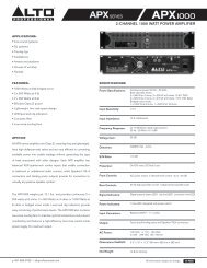
REAR PANEL DIAGRAM<br />
PUSH<br />
PUSH<br />
3<br />
4<br />
3<br />
2<br />
1<br />
5 5<br />
5 5<br />
6<br />
1. COOLING FAN- This fan secures cooling for the amplifier. The airflow is from front to rear. The fan speed is<br />
electronically regulated depending on the temperature of the power devices. Do not block these fan grills or<br />
mount the amplifier in an enclosed rack, which could cause the amplifier to overheat.<br />
2. LOW PASS FILTER – This switch activates the built-in low cut filter. All audio below 30 Hz will be removed<br />
from the output signal.<br />
3. BALANCED COMBO INPUTS – Connect your mixer to the balanced<br />
XLR or balanced 1/4" input for that channel.<br />
How do I know if my 1/4" cables<br />
are balanced?<br />
4. OUTPUT MODE SWITCH – The APX 1000 presents three operating<br />
modes:<br />
BALANCED<br />
Stereo Mode<br />
UNBALANCED<br />
In this mode, CH 1 and CH 2 operate independently (as a normal<br />
stereo amplifier) The CH 1 input signal will be output from the CH 1 output connector, and CH 2 input<br />
signal will be output from the CH 2 output<br />
connector.<br />
Parallel Mono Mode<br />
In this mode, CH 1 input signal will be output from<br />
the output connectors of both<br />
channels.<br />
Bridged Mode<br />
In this mode, CH 1 input signal will be output from<br />
the bridge-mono output connector.<br />
5. CHANNEL OUTPUTS – Connect your speakers' input<br />
jacks to these outputs.<br />
• For the binding posts, red is the positive signal<br />
and black is the negative signal. Please make<br />
WARNING!: Do not adjust the<br />
STEREO/MONO BRIDGE SWITCH when the<br />
amplifier is on.<br />
WARNING!: Do not allow any wires of<br />
adjacent terminals to come in contact with<br />
each other. Also, do not connect either<br />
positive (red) output to chassis ground.<br />
sure to respect the speaker polarity when using binding post. Turn off the unit before connecting an<br />
audio signal to the binding post to avoid any electric shock!<br />
• The SPEAKON outputs are specifically designed to connect to high power speakers. The correct polarity<br />
is secured automatically. They prevent shock hazard and they lock-in securely. Please see the<br />
SPEAKER CONNECTION section to properly and safely connect your speakers.<br />
6. POWER IN – Connect the cable to a standard wall outlet. Be sure the supplied voltage matches the required<br />
voltage of the amplifier. Do not connect the amplifier to an outlet that does not match the required voltage;<br />
doing so could damage the amplifier.<br />
3
FRONT PANEL DIAGRAM<br />
7 7<br />
3<br />
6 6<br />
4 5<br />
1<br />
7 7<br />
2<br />
1. POWER SWITCH – Turns the amplifier on/off.<br />
2. POWER LED – Illuminates when the amplifier is on.<br />
3. LED METERS – Indicates the audio signal level. This LED will light up when the signal at the output is at least -<br />
20 dB.<br />
4. CLIP – The red "Clip" light indicates the signal is distorting or "clipping," which occurs when the volume<br />
exceeds the amplifier's maximum output. This LED will flash when distortion reaches a level of 0.5%.<br />
Consistent clipping can damage your amplifier and speakers. If the signal is regularly clipping, reduce the<br />
volume of the amplifier. If it is lit about half the time, the amplifier channel's thermal protection will cause<br />
the channel to shut down within a few minutes.<br />
5. PROT – The red "Prot" light indicates the output for that channel has turned off to protect your amplifier and<br />
speakers, which can be damaged by excessive volume resulting in clipping. If the meters' red lights are<br />
illuminating, decrease the levels of your CHANNEL GAIN knobs.<br />
6. CHANNEL GAIN – This knob controls the channel's output signal.<br />
7. COOLING VENTS – These vents help to cool the internal parts of the amplifier when in use. Do not block<br />
these vents, and keep the vents clean at all times.<br />
SPEAKER CONNECTION<br />
WARNING!:<br />
• Do not make any connections when any device is powered on.<br />
• Do not allow the wires from terminals to come in contact with each other.<br />
• Do not connect either positive (red) output to chassis ground.<br />
SHORT CIRCUIT PROTECTION<br />
Output short circuit protection protects the output devices of the amplifier from short circuits and stressful loads. If<br />
your speaker lines short, the amplifier automatically detects this problem and discontinues operation for that channel.<br />
(If one channel's short circuit protection is activated, the other channel will continue to operate normally.) During<br />
short circuit protection, the "Clip" and "Protect" LEDs will light simultaneously, and all output from<br />
that channel will stop.<br />
Short Circuit Protection can often be traced back to the signal<br />
output line (i.e., the speaker line). Check the line from the<br />
output terminal of the amplifier to the speaker. If this line is still<br />
good, check the internal speaker connections and<br />
components. (A short circuit can often be traced to a bad<br />
cable or a bad speaker component and is rarely traced to the amplifier itself.)<br />
Bare Wire Connections:<br />
When connecting your speakers to the amplifier using bare wires, follow these steps:<br />
1. Unscrew the red and black caps of the binding posts. (Be sure not to completely remove or unscrew the red<br />
and black caps.)<br />
2. Strip back the wire insulation 1/2" (13mm).<br />
3. Insert the bare wire into the hole exposed under the binding post cap.<br />
4. After inserting the wire, screw the binding post cap down on the wire.<br />
Spade Connector:<br />
When connecting your speakers to the amplifier using spade connectors, follow these steps:<br />
1. Unscrew the red and black caps of the binding posts. (Be sure not to completely remove or unscrew the red<br />
and black caps.)<br />
2. Insert the spade connectors into the binding posts.<br />
3. Tighten the caps down on the spade connectors.<br />
Banana Connectors:<br />
When connecting your speakers to the amplifier using banana connectors, follow these steps<br />
1. Be sure that the red and black caps of the binding posts are tightened completely.<br />
2. Insert the banana connectors into the caps of the binding posts. Be sure that the connectors are inserted<br />
securely.<br />
4
PUSH<br />
PUSH<br />
-<br />
+<br />
+<br />
-<br />
OPERATION IN STEREO MODE<br />
The <strong>APX1000</strong> provides three operating modes: stereo mode, parallel (mono) mode and bridged mode, you can<br />
decide each specific operating mode according to your actual application circumstance.<br />
In STEREO MODE, channel 1 and channel 2 operate independently (as a conventional stereo amplifier). The channel<br />
1 input signal will be output from the channel 1 output connectors, and the channel 2 input signal will be output from<br />
the channel 2 output connectors.<br />
PUSH<br />
PUSH<br />
STEREO<br />
OPERATION IN PARALLEL MODE<br />
In this mode, the channel 1 input signal will be output from the output connectors of both channels. The channel 2<br />
input jack is not used; the channel 1 and 2 volumes can be adjusted independently. Use the Parallel Mode when you<br />
want to drive two speakers with only one input signal keeping separate control of the volume of the two channels.<br />
NOTE: Since you are not using the channel 2 input you can use this socket to "daisy-chain" to another amplifier.<br />
PARALLEL<br />
-<br />
+<br />
-<br />
+<br />
5
OPERATION IN BRIDGED MODE<br />
In this mode, the channel 1 input signal will be output from the bridge output connectors. (The 2 binding posts) In this<br />
case, use the channel 1 volume control to adjust the volume, keep the volume control of channel 2 turned<br />
completely down (counter clockwise). Bridged mode is intended for driving loads with a total impedance of 8 ohms or<br />
greater.<br />
In Bridge Mode you will combine the power of both channels into one speaker. You will have a large amount of power<br />
available so carefully check the power handling of your speaker before operation.<br />
PUSH<br />
PUSH<br />
BRIDGED<br />
-<br />
+<br />
RACKMOUNTING TIPS<br />
• It is a good idea to mount this in the bottom of a rack frame. Supporting the back of the unit may be<br />
necessary for portable or road use. The <strong>APX1000</strong> mounts into a standard 19u rackmount.<br />
• ALTO amplifiers are well shielded; however, mounting low-level electronics some distance away from power<br />
amplifiers is common practice to reduce the possibility of electromagnetic interference into the low level<br />
units, which may sometimes be unusually susceptible to picking up such interference.<br />
• When wiring a rack, it is good installation practice to route all AC wiring along one side of the rack and all<br />
audio wiring along the other side to avoid coupling AC-borne interference into the audio.<br />
6
SPECIFICATIONS<br />
POWER SPECIFICATIONS<br />
• Continuous power @ 0.5% THD: 4 Ohms 390W*2<br />
• Both channels driven: 8 Ohms 250W*2<br />
• Power EIAJ@ 1% THD 4 Ohms 500W*2<br />
• Both channels driven: 8 Ohms 270W*2<br />
• Bridge Mono Mode: 8 Ohms 1000W*1<br />
20Hz-20kHz 16 Ohms 520W*1<br />
ELECTRICAL SPECIFICATION<br />
• INPUT SENSITIVITY: 1.0V<br />
• INPUT IMPEDANCE: 10 K ohm unbalanced<br />
• FREQUENCY RESPONSE: (at 10dB below rated output power) 20 Hz~25<br />
KHz (+0/-3 dB)<br />
• VOLTAGE GAIN: 32 dB<br />
• DISTORTION: (SMPTE-1M) 110 dB<br />
• Inrush Current at initial switch on: 5.85A<br />
• Inrush Current after power supply interruption: 6.95A<br />
GENERAL SPECIFICATIONS<br />
• PROTECTIONS: ON/OFF, muting, DC-fault load grounding relay. Internal<br />
fault fuses<br />
• CONTROLS Front: AC switch<br />
• CONTROLS Rear: Low pass filter, mode selector<br />
• SIGNAL INDICATORS: 2 green LED CLIP: 2 red LED<br />
• POWER INDICATORS: 1 Blue LED PROTECTION: 1 red LED<br />
• INPUT CONNECTORS: Balanced combo<br />
• OUTPUT: "Touch-proof" binding posts and speak-on jacks<br />
DIMENSIONS<br />
• (WxLxH) 483mm x 285mm x 88.8mm; 19” x 11.2” x 3.5”<br />
WEIGHT<br />
• 12.1 lb; 5.4kg<br />
7
www.altoprofessional.com<br />
MANUAL VERSION 1.1