Heat Engines: the Carnot Cycle - Galileo and Einstein
Heat Engines: the Carnot Cycle - Galileo and Einstein
Heat Engines: the Carnot Cycle - Galileo and Einstein

You also want an ePaper? Increase the reach of your titles
YUMPU automatically turns print PDFs into web optimized ePapers that Google loves.
<strong>Heat</strong> <strong>Engines</strong>: <strong>the</strong> <strong>Carnot</strong> <strong>Cycle</strong><br />
Flashlet here!<br />
Michael Fowler Physics 142E 04/21/09<br />
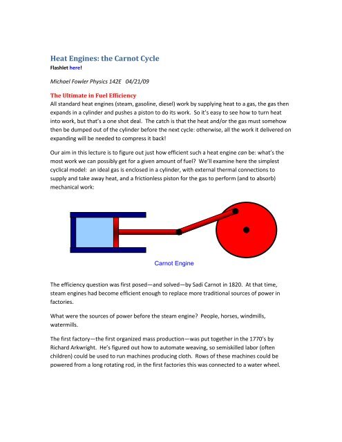
The Ultimate in Fuel Efficiency<br />
All st<strong>and</strong>ard heat engines (steam, gasoline, diesel) work by supplying heat to a gas, <strong>the</strong> gas <strong>the</strong>n<br />
exp<strong>and</strong>s in a cylinder <strong>and</strong> pushes a piston to do its work. So it’s easy to see how to turn heat<br />
into work, but that’s a one shot deal. The catch is that <strong>the</strong> heat <strong>and</strong>/or <strong>the</strong> gas must somehow<br />
<strong>the</strong>n be dumped out of <strong>the</strong> cylinder before <strong>the</strong> next cycle: o<strong>the</strong>rwise, all <strong>the</strong> work it delivered on<br />
exp<strong>and</strong>ing will be needed to compress it back!<br />
Our aim in this lecture is to figure out just how efficient such a heat engine can be: what’s <strong>the</strong><br />
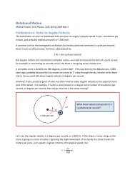
most work we can possibly get for a given amount of fuel? We’ll examine here <strong>the</strong> simplest<br />
cyclical model: an ideal gas is enclosed in a cylinder, with external <strong>the</strong>rmal connections to<br />
supply <strong>and</strong> take away heat, <strong>and</strong> a frictionless piston for <strong>the</strong> gas to perform (<strong>and</strong> to absorb)<br />
mechanical work:<br />
<strong>Carnot</strong> Engine<br />
The efficiency question was first posed—<strong>and</strong> solved—by Sadi <strong>Carnot</strong> in 1820. At that time,<br />
steam engines had become efficient enough to replace more traditional sources of power in<br />
factories.<br />
What were <strong>the</strong> sources of power before <strong>the</strong> steam engine? People, horses, windmills,<br />
watermills.<br />
The first factory—<strong>the</strong> first organized mass production—was put toge<strong>the</strong>r in <strong>the</strong> 1770’s by<br />
Richard Arkwright. He’s figured out how to automate weaving, so semiskilled labor (often<br />
children) could be used to run machines producing cloth. Rows of <strong>the</strong>se machines could be<br />
powered from a long rotating rod, in <strong>the</strong> first factories this was connected to a water wheel.
2<br />
Obviously, profits were maximized if <strong>the</strong> water wheel was made as efficient as possible, <strong>and</strong> a<br />
lot of engineering <strong>and</strong> thought went into figuring out how best to do this. The water loses<br />
potential energy as it is carried down by <strong>the</strong> wheel, so <strong>the</strong> most energy possible is mgh watts,<br />
where m is <strong>the</strong> mass of water flowing per second.<br />
How is energy wasted? First, we need as little friction in <strong>the</strong> wheel as possible. We need<br />
smooth flow: no water splashing around. The water must flow into <strong>and</strong> off <strong>the</strong> wheel without<br />
dropping any significant height, or it loses that much potential energy without producing work.<br />
A perfect water wheel would be reversible: it could be used to drive a copy of itself backwards,<br />
to lift up <strong>the</strong> same amount of water per second that fell.<br />
A Modern Water Wheel in Virginia<br />
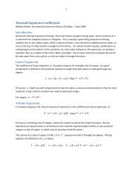
There is in Virginia a pretty efficient water wheel: it’s about 80% efficient—<strong>the</strong> Bath County<br />
hydroelectric pumped storage station. This is a water wheel, actually a turbine, but that<br />
amounts to <strong>the</strong> same thing better designed, that works both ways. Water from an upper lake<br />
falls through a pipe to a turbine <strong>and</strong> <strong>the</strong> lower lake, generating electrical power. Alternatively,<br />
electric power can be supplied to pump <strong>the</strong> water back up. Why bo<strong>the</strong>r? Because dem<strong>and</strong> for<br />
electricity varies, <strong>and</strong> it’s better to avoid if possible building power stations that are only running<br />
during peak dem<strong>and</strong>. It’s cheaper to store power at times of low dem<strong>and</strong>.<br />
The drop h is about 1200 feet, 380 meters. The flow rate is about a thous<strong>and</strong> tons a second. The<br />
plant generates about 2 Gigawatts, roughly <strong>the</strong> same as a two-unit nuclear plant.<br />
<strong>Carnot</strong>’s Idea: a “Water Wheel” for <strong>Heat</strong><br />
About two hundred years ago, in <strong>Carnot</strong>’s time, heat was widely believed to be a fluid, called <strong>the</strong><br />
“caloric fluid” that flowed inside materials from hot to cold, just as <strong>the</strong> electric “fluid” flowed<br />
from high potential to low potential. We now know, of course, that <strong>the</strong>y were right about<br />
electric current, but wrong about heat. Never<strong>the</strong>less, <strong>the</strong> picture of fluid flow accurately<br />
describes heat flow as long as no work is done—all discussions of <strong>the</strong>rmal conductivity, or <strong>the</strong><br />
heat flow in cooking, etc., are still best pictures in those terms.<br />
Anyway, following <strong>the</strong> analogy of electric current flowing from high potential to low potential,<br />
or water flowing downhill to lower gravitational potential, <strong>Carnot</strong> figured that for heat flow, <strong>the</strong><br />
temperature was <strong>the</strong> appropriate potential, <strong>and</strong> <strong>the</strong> steam engine was like a water wheel for<br />
this caloric fluid, so <strong>the</strong> most efficient engine would have minimal friction, but also, in analogy<br />
with <strong>the</strong> water entering <strong>and</strong> leaving <strong>the</strong> wheel gently with no intermediate loss of height, <strong>the</strong><br />
heat would enter <strong>and</strong> leave <strong>the</strong> gas in <strong>the</strong> engine iso<strong>the</strong>rmally (remember <strong>the</strong> temperature is<br />
analogous to <strong>the</strong> gravitational potential, thus <strong>the</strong> height). Therefore, by analogy with mgh, <strong>the</strong><br />
drop in temperature T H – T C measures <strong>the</strong> potential energy given up by <strong>the</strong> “heat fluid”.<br />
But how does that relate to <strong>the</strong> energy expended producing <strong>the</strong> heat in <strong>the</strong> first place? Well,<br />
<strong>Carnot</strong> knew something else: <strong>the</strong>re was an absolute zero of temperature. Therefore, he<br />
reasoned, if you cooled <strong>the</strong> fluid down to absolute zero, it would give up all its heat energy. So,
3<br />
<strong>the</strong> maximum possible amount of energy you can extract by cooling it from T H to T C is, what<br />
fraction is that of cooling it to absolute zero?<br />
It’s just<br />
(T H – T C )/T H .<br />
Of course, <strong>the</strong> caloric fluid picture isn’t right, but this result is! This is <strong>the</strong> maximum efficiency<br />
of a perfect engine.<br />
Getting work out of a Hot Gas<br />
Now let’s turn to <strong>the</strong> details of getting work out of a heated gas. We want <strong>the</strong> process to be as<br />
close to reversible as possible: <strong>the</strong>re are two ways to move <strong>the</strong> piston reversibly: iso<strong>the</strong>rmally,<br />
meaning heat gradually flows in or out, from a reservoir at a temperature infinitesimally<br />
different from that of <strong>the</strong> gas in <strong>the</strong> piston, <strong>and</strong> adiabatically, in which <strong>the</strong>re is no heat exchange<br />
at all, <strong>the</strong> gas just acts like a spring.<br />
So, as <strong>the</strong> heat is supplied <strong>and</strong> <strong>the</strong> gas exp<strong>and</strong>s, <strong>the</strong> temperature of <strong>the</strong> gas must stay <strong>the</strong> same<br />
as that of <strong>the</strong> heat supply (<strong>the</strong> “heat reservoir”): <strong>the</strong> gas is exp<strong>and</strong>ing iso<strong>the</strong>rmally. Similarly, it<br />
must contract iso<strong>the</strong>rmally later in <strong>the</strong> cycle as it sheds heat.<br />
To figure out <strong>the</strong> efficiency, we need to track <strong>the</strong> engine through a complete cycle, finding out<br />
how much work it does, how much heat is taken in from <strong>the</strong> fuel, <strong>and</strong> how much heat is dumped<br />
in getting ready for <strong>the</strong> next cycle. You might want to look at <strong>the</strong> flashlet to get <strong>the</strong> picture at<br />
this point: <strong>the</strong> cycle has four steps, an iso<strong>the</strong>rmal expansion as heat is absorbed, followed by an<br />
adiabatic expansion, <strong>the</strong>n an iso<strong>the</strong>rmal contraction as heat is shed, finally an adiabatic<br />
contraction to <strong>the</strong> original configuration. We’ll take it one step at a time.<br />
Step 1: Iso<strong>the</strong>rmal Expansion<br />
So <strong>the</strong> first question is: How much heat is supplied, <strong>and</strong> how much work is done, as <strong>the</strong> gas<br />
exp<strong>and</strong>s iso<strong>the</strong>rmally? Taking <strong>the</strong> temperature of <strong>the</strong> heat reservoir to be T H (H for hot), <strong>the</strong><br />
exp<strong>and</strong>ing gas follows <strong>the</strong> iso<strong>the</strong>rmal path<br />
PV nRT in <strong>the</strong> (P, V) plane.<br />
H
4<br />
P<br />
P a<br />
a<br />
P b<br />
b<br />
V a<br />
ΔV<br />
V b<br />
V<br />
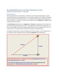
Iso<strong>the</strong>rmal expansion from a to b along PV = nRT H<br />
The work done by <strong>the</strong> gas in a small volume expansion<br />
curve (as we proved in <strong>the</strong> last lecture).<br />
V<br />
is just P<br />
V<br />
, <strong>the</strong> area under <strong>the</strong><br />
Hence <strong>the</strong> work done in exp<strong>and</strong>ing iso<strong>the</strong>rmally from volume V a to V b is <strong>the</strong> total area under <strong>the</strong><br />
curve between those values,<br />
V<br />
b<br />
b<br />
nRTH<br />
Vb<br />
work done iso<strong>the</strong>rmally PdV <br />
dV nRTH<br />
ln .<br />
V<br />
V<br />
Va<br />
V<br />
Va<br />
a<br />
Since <strong>the</strong> gas is at constant temperature T H , <strong>the</strong>re is no change in its internal energy during this<br />
V<br />
expansion, so <strong>the</strong> total heat supplied must be nRT ln b<br />
H<br />
, <strong>the</strong> same as <strong>the</strong> external work <strong>the</strong><br />
V<br />
gas has done.<br />
In fact, this iso<strong>the</strong>rmal expansion is only <strong>the</strong> first step: <strong>the</strong> gas is at <strong>the</strong> temperature of <strong>the</strong> heat<br />
reservoir, hotter than its o<strong>the</strong>r surroundings, <strong>and</strong> will be able to continue exp<strong>and</strong>ing even if <strong>the</strong><br />
heat supply is cut off. To ensure that this fur<strong>the</strong>r expansion is also reversible, <strong>the</strong> gas must not<br />
be losing heat to <strong>the</strong> surroundings. That is, after <strong>the</strong> heat supply is cut off, <strong>the</strong>re must be no<br />
fur<strong>the</strong>r heat exchange with <strong>the</strong> surroundings, <strong>the</strong> expansion must be adiabatic.<br />
Step 2: Adiabatic Expansion<br />
By definition, no heat is supplied in adiabatic expansion, but work is done.<br />
The work <strong>the</strong> gas does in adiabatic expansion is like that of a compressed spring exp<strong>and</strong>ing<br />
against a force—equal to <strong>the</strong> work needed to compress it in <strong>the</strong> first place, for an ideal (<strong>and</strong><br />
perfectly insulated) gas. So adiabatic expansion is reversible.<br />
a
5<br />
adiabat V c b<br />
<br />
<br />
W nC T T —this is <strong>the</strong> loss of internal energy by <strong>the</strong> gas on exp<strong>and</strong>ing against <strong>the</strong><br />
external pressure.<br />
Steps 3 <strong>and</strong> 4: Completing <strong>the</strong> <strong>Cycle</strong><br />
We’ve looked in detail at <strong>the</strong> work a gas does in exp<strong>and</strong>ing as heat is supplied (iso<strong>the</strong>rmally) <strong>and</strong><br />
when <strong>the</strong>re is no heat exchange (adiabatically). These are <strong>the</strong> two initial steps in a heat engine,<br />
but it is necessary for <strong>the</strong> engine to get back to where it began, for <strong>the</strong> next cycle. The general<br />
idea is that <strong>the</strong> piston drives a wheel (as in <strong>the</strong> diagram at <strong>the</strong> beginning of this lecture), which<br />
continues to turn <strong>and</strong> pushes <strong>the</strong> gas back to <strong>the</strong> original volume.<br />
But it is also essential for <strong>the</strong> gas to be as cold as possible on this return leg, because <strong>the</strong><br />
wheel is now having to expend work on <strong>the</strong> gas, <strong>and</strong> we want that to be as little work as<br />
possible—it’s costing us. The colder <strong>the</strong> gas, <strong>the</strong> less pressure <strong>the</strong> wheel is pushing against.<br />
To ensure that <strong>the</strong> engine is as efficient as possible, this return path to <strong>the</strong> starting point<br />
<br />
P,<br />
V<br />
a<br />
a<br />
<br />
must also be reversible. We can’t just retrace <strong>the</strong> path taken in <strong>the</strong> first two legs, that<br />
would take all <strong>the</strong> work <strong>the</strong> engine did along those legs, <strong>and</strong> leave us with no net output. Now<br />
<strong>the</strong> gas cooled during <strong>the</strong> adiabatic expansion from b to c, from T H to T C , say, so we can go some<br />
distance back along <strong>the</strong> reversible colder iso<strong>the</strong>rm T C . But this won’t get us back to P,<br />
V ,<br />
because that’s on <strong>the</strong> T H iso<strong>the</strong>rm. The simplest option—<strong>the</strong> one chosen by <strong>Carnot</strong>—is to<br />
proceed back along <strong>the</strong> cold iso<strong>the</strong>rm to <strong>the</strong> point where it intersects <strong>the</strong> adiabat through a,<br />
<strong>the</strong>n follow that adiabat back to a. That route keeps <strong>the</strong> gas as cold as possible for as long as<br />
possible, minimizing <strong>the</strong> external work needed to get it back to <strong>the</strong> original state.<br />
To picture <strong>the</strong> <strong>Carnot</strong> cycle in <strong>the</strong> (P, V) plane, recall from <strong>the</strong> previous lecture <strong>the</strong> graph<br />
showing two iso<strong>the</strong>rms <strong>and</strong> two adiabats:<br />
a<br />
a
Pressure in Atmospheres<br />
6<br />
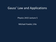
Iso<strong>the</strong>rms <strong>and</strong> Adiabats for One Mole<br />
25<br />
20<br />
15<br />
10<br />
5<br />
0<br />
0 2 4 6 8 10<br />
Volume in Liters<br />
<strong>Carnot</strong>’s cycle is around that curved quadrilateral having <strong>the</strong>se four curves as its sides.<br />
Let us redraw this, slightly less realistically but more conveniently:<br />
a<br />
P<br />
d<br />
b<br />
c<br />
c<br />
V<br />
h<br />
g<br />
f<br />
e<br />
c
7<br />
Efficiency of <strong>the</strong> <strong>Carnot</strong> Engine<br />
In a complete cycle of <strong>Carnot</strong>’s heat engine, <strong>the</strong> gas traces <strong>the</strong> path abcd. The important<br />
question is: what fraction of <strong>the</strong> heat supplied from <strong>the</strong> hot reservoir (along <strong>the</strong> red top<br />
iso<strong>the</strong>rm), let’s call it Q H , is turned into mechanical work? This fraction is called <strong>the</strong> efficiency of<br />
<strong>the</strong> engine.<br />
Since <strong>the</strong> internal energy of <strong>the</strong> gas is <strong>the</strong> same at <strong>the</strong> end of <strong>the</strong> cycle as it was at <strong>the</strong><br />
beginning—it’s back to <strong>the</strong> same P <strong>and</strong> V—it must be that <strong>the</strong> work done equals <strong>the</strong> net heat<br />
supplied,<br />
W = Q H – Q C<br />
Q C being <strong>the</strong> heat dumped as <strong>the</strong> gas is compressed along <strong>the</strong> cold iso<strong>the</strong>rm.<br />
The efficiency is <strong>the</strong> fraction of <strong>the</strong> heat input that is actually converted to work, so<br />
Efficiency = W/Q H = (Q H – Q C )/Q H<br />
This is <strong>the</strong> answer, but it’s not particularly useful: measuring heat flow, especially <strong>the</strong> waste<br />
heat, is quite difficult. In fact, it was long believed that <strong>the</strong> heat flow out was equal to that<br />
flowing in, <strong>and</strong> this was quite plausible because <strong>the</strong> efficiency of early engines was very low.<br />
But <strong>the</strong>re’s a better way to express this.<br />
Now <strong>the</strong> heat supplied along <strong>the</strong> initial hot iso<strong>the</strong>rmal path ab is equal to <strong>the</strong> work done along<br />
that leg, (from <strong>the</strong> paragraph above on iso<strong>the</strong>rmal expansion):<br />
Q<br />
H<br />
nRT<br />
H<br />
V<br />
ln b<br />
V<br />
a<br />
<strong>and</strong> <strong>the</strong> heat dumped into <strong>the</strong> cold reservoir along cd is<br />
Q<br />
C<br />
nRT<br />
C<br />
Vc<br />
ln .<br />
V<br />
d<br />
Q H – Q C looks complicated, but actually it isn’t!<br />
The expression can be greatly simplified using <strong>the</strong> adiabatic equations for <strong>the</strong> o<strong>the</strong>r two sides of<br />
<strong>the</strong> cycle:<br />
T V<br />
T V<br />
1 1<br />
H b C c<br />
T V<br />
1 <br />
1<br />
H a<br />
TCV<br />
d<br />
.<br />
Dividing <strong>the</strong> first of <strong>the</strong>se equations by <strong>the</strong> second,
8<br />
<strong>and</strong> using that in <strong>the</strong> preceding equation for Q C ,<br />
V <br />
b<br />
V <br />
c<br />
<br />
V V<br />
a d <br />
Va<br />
TC<br />
QC nRTC ln QH<br />
.<br />
V T<br />
So for <strong>the</strong> <strong>Carnot</strong> cycle <strong>the</strong> ratio of heat supplied to heat dumped is just <strong>the</strong> ratio of <strong>the</strong><br />
absolute temperatures!<br />
QH TH QH<br />
QC<br />
, or .<br />
Q T T T<br />
C C H C<br />
Remember this: it’ll be important in developing <strong>the</strong> concept of entropy.<br />
The work done can now be written simply:<br />
T <br />
C<br />
W QH QC 1 QH<br />
.<br />
TH<br />
<br />
Therefore <strong>the</strong> efficiency of <strong>the</strong> engine, defined as <strong>the</strong> fraction of <strong>the</strong> ingoing heat energy that<br />
is converted to available work, is<br />
efficiency W TC<br />
1 .<br />
Q<br />
T<br />
These temperatures are of course in degrees Kelvin, so for example <strong>the</strong> efficiency of a <strong>Carnot</strong><br />
engine having a hot reservoir of boiling water <strong>and</strong> a cold reservoir ice cold water will be<br />
1 (273/373) 0.27 , just over a quarter of <strong>the</strong> heat energy is transformed into useful work.<br />
This is <strong>the</strong> very same expression <strong>Carnot</strong> found from his water wheel analogy.<br />
After all <strong>the</strong> effort to construct an efficient heat engine, making it reversible to eliminate<br />
“friction” losses, etc., it is perhaps somewhat disappointing to find this figure of 27% efficiency<br />
when operating between 0 <strong>and</strong> 100 degrees Celsius. Surely we can do better than that? After<br />
all, <strong>the</strong> heat energy of hot water is <strong>the</strong> kinetic energy of <strong>the</strong> moving molecules, can’t we find<br />
some device to channel all that energy into useful work? Well, we can do better than 27%, by<br />
having a colder cold reservoir, or a hotter hot one. But <strong>the</strong>re’s a limit: we can never reach 100%<br />
efficiency, because we cannot have a cold reservoir at T 0 K,<br />
<strong>and</strong>, even if we did, after <strong>the</strong><br />
first cycle <strong>the</strong> heat dumped into it would warm it up!<br />
b<br />
H<br />
H<br />
C<br />
H