INSTALLATION INSTRUCTIONS - Baker Drivetrain
INSTALLATION INSTRUCTIONS - Baker Drivetrain
INSTALLATION INSTRUCTIONS - Baker Drivetrain

You also want an ePaper? Increase the reach of your titles
YUMPU automatically turns print PDFs into web optimized ePapers that Google loves.
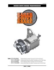
<strong>INSTALLATION</strong> <strong>INSTRUCTIONS</strong><br />
V9-51508
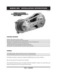
Features Overview<br />
In our plight for <strong>Drivetrain</strong> perfection, we have come out with another innovation to make the riding<br />
experience on your American motorcycle, the pleasure it should be. We are proud to announce the release<br />
of the BAKER Reverse Kit, F6R for short.The BAKER Reverse system is unlike any other on the<br />
market in that it works off the stock foot shifter lever. With the simple hit of the Reverse Safety Toggle<br />
Switch, and a flick of your foot, you are in Reverse. It is that simple. No reaching near hot pipes to put a<br />
bike in Reverse anymore. The BAKER Reverse system is designed so that it is impossible to get a bike<br />
locked in 1st and Reverse, like on some other models out there. Additionally the Reverse Gears are all<br />
fully heat treated, diamond ground, gear grade 8620 steel. The BAKER Reverse shift drum also improves<br />
greatly over the ability to find neutral than stock. With an overall 4.98:1 gear ratio in Reverse, 45% shorter<br />
than the stock 3.34:1 first gear, it is essentially a creeper gear. There are also no problems with stock<br />
exhaust clearance. Also compatible with our previously release F6F kit.<br />
Fitment:<br />
2006-2008 Dyna’s<br />
2007-2008 Softails & FLT/FLH Models<br />
getting started/TOOLS<br />
Getting Started<br />
The BAKER F6R System is designed in such a manner that any competent mechanic or dealership that<br />
is familiar with the new H-D Cruise Drive Transmissions can handle the job. While regularly referring to<br />
the Factory Service Manual for your bike, (A must for this kit) as well our multiple diagrams and in depth<br />
instructions, there should not be any issues with the conversion process. While the BAKER F6R was<br />
designed to be as easy an install as possible, this is probably not the job for a weekend warrior as there is<br />
no substitute for experience.<br />
Tools & Parts<br />
Common hand tools, sockets, allen wrenches and<br />
snap ring pliers will suffice for a majority of the job,<br />
while a few specialty tools that are required are<br />
listed out below. BAKER does sell some of our<br />
own drivetrain related tools as well, the P/N’s are<br />
listed out below.<br />
-1 3/16” 6 pt Socket (Clutch Sprocket Nut)<br />
-1 1/16” 6 pt Socket (Tranny Shaft Nylock Nuts)<br />
-1 3/8” 6 pt Socket (Countershaft Base Nut)<br />
-Primary Inner Race Service Kit (BAKER TOOLB-56)<br />
-Split Bearing Puller (BAKER P/N: 483-6T)<br />
-45 oz of Primary Fluid (Spectro Heavy Duty Primary<br />
Chain Case Oil (Spectro P/N: R.GAPCL)<br />
-‘Blue’ Thread Lock<br />
-‘Red’ Thread Lock<br />
-Access To A 20 Ton Hydraulic Press<br />
-‘Silver’ Anti Seize<br />
-Black Zip Ties<br />
-32 Oz Of Transmission Fluid: BAKER recommends<br />
Spectro Oils.<br />
Hydrualic Side Cover Version<br />
-DOT 5 Silicone Brake Fluid (Spectro P/N I.GABF)<br />
-11/16” Bore Hydraulic Clutch Lever<br />
-3AN Brake line<br />
-3/8-24 Banjo Bolt<br />
-10mm Brake Line Fittings<br />
Customers installing a BAKER F6R on Screaming<br />
Eagle bikes with Factory installed Hydraulic side<br />
covers will need to purchase the following parts from<br />
their local Harley-Davidson dealer:<br />
P/N: 37090-98A Center Push Rod Qty: 1<br />
P/N: 37092-06 Screw Adjuster Qty: 1<br />
P/N: 37903-90 Release Plate Qty: 1<br />
P/N: 37909-90 Retaining Ring, Internal Qty: 1<br />
P/N: 7848W Jam Nut Qty: 1<br />
These parts retro-fit the clutch rod and adjustment<br />
to a mechanical, ball and ramp, side cover set up to<br />
work with the BAKER 1.5” piston and push rod in the<br />
F6R Sidecover.<br />
PAGE 1 | GETTING STARTED/TOOLS<br />
V9-51508
table of contents:<br />
<strong>Baker</strong> F6R Table of Contents:<br />
Cover<br />
1. Reverse System Overview & Tools<br />
2. Table of Contents<br />
3. Reverse Bearing Door Components<br />
4. Exploded View Of Reverse Gears<br />
5. Reverse Side Cover Contents, Mechanical<br />
6. Reverse Side Cover Contents, Hydraulic<br />
7. Disassembly Of Bike, Pull Stock Gearset Cassette<br />
8. Disassembly Stock Gearset Cassette<br />
9. Reverse Countershaft Assembly<br />
10. Pressing Mainshaft Into Reverse Bearing Door<br />
11. Pressing Countershaft into Reverse Bearing Door<br />
12-13. Shift System & F6R Gearset Cassette<br />
14. Installation Of Reverse Gears<br />
15. Reverse Side Install, Mechanical<br />
16. Reverse Side Install, Hydraulic<br />
17. Reverse Solenoid Install<br />
18. Reverse Safety Switch & Harness FLH-Fairing Models<br />
19. Reverse Safety Switch & Harness Road Glide Models<br />
20. Reverse Satety Switch & Harness-Non-Fairing Models (Dyna, Softail, Road King)<br />
21. Final Bike Assembly, Reverse Operation & Maiden Voyage<br />
22. Terms<br />
23. Disclaimer<br />
PAGE 2 | table of contents<br />
V9-51508
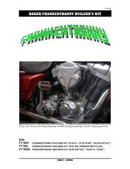
AKER f6r -INCLUDED PARTS:<br />
17<br />
2<br />
1<br />
5,6,7<br />
18<br />
19<br />
20<br />
12<br />
8,9,10,11<br />
21<br />
13<br />
14<br />
15<br />
16<br />
22<br />
3,4<br />
3,4<br />
STOCK<br />
EXHAUST<br />
BRACKET<br />
23<br />
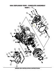
Figure 1<br />
Reverse Bearing Door Components<br />
Tag P/N DESCRIPTION QTY<br />
1 400-RV07 Reverse Bearing Door 1<br />
2 31C125KCSS/P 5/16-18 x 1.25 SHCS, SS, Polished 6<br />
3 31C175KCSS/P 5/16-18 x 1.75 SHCS, SS, Polished 2<br />
4 6100 5/16 AN Washer 2<br />
5 402-RV07 Reverse Shift Drum 1<br />
6 61807 Shift Drum Bearing 1<br />
7 403-RV07 Shift Drum Nut 1<br />
8 RV-7040 Reverse Countershaft 1<br />
9 168-6N4 7/8-14 Thread, Countershaft Base Nut 1<br />
10 6205 Countershaft Bearing 1<br />
11 406-RV07 Retainer Plate, Countershaft 1<br />
12 24050 1/4-20 x 5/8 BHCS, Black 6<br />
13 RV-7050 Mainshaft Retainer Nut 1<br />
14 RV-7000 Mainshaft Pinion Gear 1<br />
15 6007 Mainshaft Bearing 1<br />
16 407-RV07 Retainer Plate, Mainshaft 1<br />
17 26749 1/4 x 1/2 Solid Dowel 2<br />
18 Hk1412 Split Idler Gear Bearing 2<br />
19 408-RV07 Retainer Plate, Shift Drum 1<br />
20 10C50KCS 10-24 x 1/2 SHCS, Black 3<br />
21 137RRRE Pinion Gear Snap Ring 1<br />
22 LS2542 Countershaft Spacer (.984” x 1.654” x .118”) 1<br />
23 16583-00 10mm Hollow Dowel 2<br />
PAGE 3 | INCLUDED PARTS DETAIL<br />
V9-51508
AKER f6r -INCLUDED PARTS:<br />
1<br />
2<br />
8<br />
7<br />
Mainshaft RETAINER<br />
7<br />
ACTUATOR ROD<br />
3<br />
Countershaft BASE NUT<br />
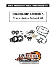
Figure 2<br />
6<br />
5<br />
4<br />
Reverse Gear Components<br />
Tag P/N DESCRIPTION QTY<br />
1 413-RV07 Reverse Side Cover Gasket 1<br />
2 412-RV07 Reverse Fork Rod 1<br />
3 404-RV07 Reverse Shift Fork 1<br />
4 RV-7020 Reverse Slide Gear 1<br />
5 RV-7030 Reverse Dog Clutch 1<br />
6 62FNTE0Z 5/8-18 Nylock Jam Nut 1<br />
7 TRA-916 Thrust Washer, Spilt Idler Gear 2<br />
8 RV7010 Split Idler Gear 1<br />
PAGE 4 | INCLUDED PARTS DETAIL<br />
V9-51508
AKER f6r -INCLUDED PARTS:<br />
1<br />
9<br />
3<br />
2<br />
8<br />
5<br />
7 6 4<br />
11<br />
10<br />
12-17<br />
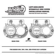
Reverse Mechanical Side Cover Components<br />
Figure 3<br />
Tag P/N DESCRIPTION QTY<br />
1 S-06231 Reverse Safety Solenoid, R16 x16 1<br />
2 66827 Solenoid O-Ring (11/16 x 7/8 x 3/32) 1<br />
3 LP 026K 01 S316 Safety Return Spring, (3/4” Long) 1<br />
4 182-1027-001 Solenoid Plunger 1<br />
5 716NWSFS Spring Seat Washer 1<br />
6 91665A350 Spiral Snap Ring (7/16” Shaft) 1<br />
7 12R50PRP0P 1/8 “ x 1/2” Split Roll Pin 1<br />
8 409-RV07 Reverse Safety Lever 1<br />
9 25R100PDP 1/4” x 1 Pull Dowel 1<br />
10 401-RV07 Reverse Side Cover, Mechanical 1<br />
11 HK1412 Split Ilder Gear Bearing 2<br />
12 37089-84 Clutch Rod Assy, Mech (2.625” Overall) 1<br />
13 WT3196 Outer Ball Ramp 1<br />
14 987687 3/8” OD Ball Bearings 3<br />
15 WT3096 Inner Ball Ramp 1<br />
16 3094-DSSC Clutch Cable Ferrule 1<br />
17 68067 Snap Ring, Ball & Ramp Retainer 1<br />
PAGE 5 | INCLUDED PARTS DETAIL<br />
V9-51508
AKER f6r -INCLUDED PARTS:<br />
1<br />
9<br />
3<br />
2<br />
8<br />
5<br />
7 6 4<br />
11<br />
12<br />
10<br />
13-15<br />
Figure 4<br />
Reverse Hydrualic Side Cover Components<br />
Tag P/N DESCRIPTION QTY<br />
1 S-06231 Reverse Safety Solenoid, R16x16 1<br />
2 66827 Solenoid O-Ring (11/16x7/8x3/32) 1<br />
3 LP 026K 01 S316 Safety Return Spring, (3/4” Long) 1<br />
4 182-1027-001 Solenoid Plunger 1<br />
5 716NWSFS Spring Seat Washer 1<br />
6 91665A350 Spiral Snap Ring (7/16” Shaft) 1<br />
7 12R50PRP0P 1/8 x 1/2 Split Roll Pin 1<br />
8 409-RV07 Reverse Safety Lever 1<br />
9 25R100PDP 1/4 x 1 Pull Dowel 1<br />
10 410-RV07 Reverse Side Cover, Hydrualic 1<br />
11 HK1412 Split Idler Gear Bearing 2<br />
12 94-4508 Bleeder Valve 1<br />
13 37084-84L Clutch Rod Assy, Hydraulic (2.815” Overall) 1<br />
14 124-56L Hydraulic Piston, 1.500”Dia, LSD 1<br />
15 66855 Hydrualic Piston O-Ring (1 1/4” x 1 1/2” x 1/8) 2<br />
PAGE 6 | INCLUDED PARTS DETAIL<br />
V9-51508
aker F6R -Disassembly:<br />
Disassembly<br />
Whereas it may seem as we are skimming over many of the steps, your Factory Service Manual will lay<br />
out in detail the proper methods for removal and reassembly of the components listed out in the steps<br />
within these instructions. Softails, Dyna’s and FLT/FLH’s are all different configurations and require<br />
a different order and method to accomplish the various steps.If you are in the process of installing a<br />
Lehman Trike Conversion, wait until after you complete the BAKER F6R installation to remove the rear<br />
wheel, swingarm, and rear brake.<br />
<br />
Similar to any other <strong>Drivetrain</strong> related project, the first steps that you want to take<br />
are to remove the seat and disconnect the battery for your own safety.<br />
Now is a good time to get out a couple of drain pans and drain the primary fluid as well as the<br />
transmission fluid. For location of the applicable drain plugs, check your Factory Service Manual.<br />
Next remove the saddlebags, (if applicable), then the floorboards/pegs and the pipes. Remember to<br />
disconnect the O2 sensor plugs from the pipes so as to not damage them when pulling the pipes off.<br />
Unbolt the starter, pull it out and set aside on your workbench. Pull off the outer primary, the primary<br />
chain, clutch assembly and the inner primary. Having a drip pan underneath the bike when you are taking<br />
off the outer primary is a great idea as residual oil will get all over your lift or garage floor depending on<br />
your work environment. Pull the bearing race found on the mainshaft next with your Inner Race Service<br />
tool. You can not pull the gearset out of the case without first removing this bearing race.<br />
Loosen the bolts on the transmission side cover, pull it off detach from the clutch cable and set it aside.<br />
The side cover along with the factory ball and ramp will not re-used with the BAKER F6R kit.<br />
<br />
REMOVE THE TRANSMISSION DIPSTICK AT THIS TIME AS WELL; YOU CAN NOT PULL THE GEARSET<br />
WITH THE DIPSTICK IN THE TRANSMISSION. IT WILL BREAK OFF IF YOU LEAVE IT IN THE<br />
TRANSMISSION WHEN ATTEMPTING TO PULL THE GEARSET.<br />
Remove the top cover and set aside, this is necessary so that you can pull the shifter pawl off of the drum<br />
when you remove the entire gearset and trap door assembly. According to the Factory Service Manual,<br />
you want to place the shifter pawl on the top cover mounting surface with the gasket acting as a ‘pad’<br />
while pulling the gearset.<br />
Using a 1-1/16” 6 pt socket, you need to loosen the nylock jam nuts on both the countershaft and<br />
mainshaft before you remove the gearset from the case. A good trick is to stand with your right foot on the<br />
rear brake pedal while trying to loosen the jam nuts with a breaker bar.<br />
<br />
DO NOT USE AN IMPACT GUN TO REMOVE THE SHAFT JAM NUTS AS IT HAS A GREAT TENDENCY TO<br />
DAMAGE THE THREADS OF THE Mainshaft THAT YOU NEED TO REUSE.<br />
(Disassembly Continued on next page)<br />
PAGE 7 | disassembly<br />
V9-51508
aker f6r -DISASSEMBLY:<br />
(Disassembly Continued)<br />
Now you can unbolt the trap door from the case and pull the gearset. Lightly tap on the end of the mainshaft<br />
on the primary side with a rubber mallet to loosen the entire gearset and trap door from the case.<br />
You do not need to loosen the drive sprocket or remove the 6th main bottle gear to install this kit.<br />
<br />
DO NOT HIT THE END OF THE MAINSHAFT WITH A BALL PEEN HAMMER, OR ANY OTHER METAL<br />
HEADED HAMMER. HITTING THE MAINSHAFT WITH A GREAT AMOUNT FORCE IN ANY MANNER, WITH<br />
ANY HAMMER, WILL DAMAGE THE THREADS. YOU MUST REUSE YOUR STOCK MAINSHAFT AND WANT<br />
TO TAKE GREAT CARE NOT TO DAMAGE IT IN ANY WAY. IF YOU FEEL THAT YOU DO NEED TO USE A<br />
GREAT DEAL OF FORCE TO REMOVE THE GEARSET, STOP AND LOOK OVER ALL OF YOUR PREVIOUS<br />
STEPS AS YOU MAY HAVE FORGOTTEN TO REMOVE A BOLT, THE MAINSHAFT BEARING RACE, MOVED<br />
THE SHIFTER PAWL OR SOME OTHER SOLID OBJECT IS IMPEDING THE PATH OF THE GEARSET<br />
BEFORE YOU PROCEED.<br />
Once you have successfully removed the gearset from the case and have it sitting with the trap door<br />
on a workbench with the shafts pointing in the air, refer to your Factory Service Manual for the safe and<br />
efficient way to strip the assembly down to the trap door. You will be reusing the mainshaft and all of its<br />
gears.<br />
Following the service manual, disassemble the countershaft down to 5th gear. You will then need to<br />
use a Split Bearing Press Tool to ‘press’ the stock 5th gear off of the countershaft. You then, similar to<br />
the picture, need to press the gear off of the shaft. You must ensure that you have everything lined up<br />
completely vertical and parallel to the ram on the press. Getting the gear cocked or crooked on the shaft<br />
can and will result in both gear and countershaft damage.<br />
<br />
Figure 5 Figure 6<br />
<br />
ANY TIME THAT YOU ARE USING A HYDRAULIC PRESS OF ANY SIZE, CARE NEEDS TO BE TAKEN TO<br />
MAKE SURE THAT YOU ARE OPERATING THE PRESS IN A SAFE MANNER AND THAT THE MACHINE IS<br />
IN GOOD WORKING ORDER. USING ADEQUATE AND SOLID PIECES OF MATERIAL TO PUSH ON THE<br />
COUNTERSHAFT WILL PREVENT IT FROM SLIPPING OUT OF THE STACK WHILE UNDER LOAD. IT IS<br />
COMPLETELY IN YOUR BEST INTEREST AND PERSONAL SAFETY TO BE CAREFUL IN YOUR HYDRAULIC<br />
PRESS OPERATION.<br />
PAGE 8| assembly<br />
V9-51508
aker f6r - ASSEMBLY:<br />
Assembly<br />
1. Once you have removed the stock 5th gear<br />
from the Countershaft, you are ready to press<br />
that gear onto the BAKER Reverse Countershaft.<br />
Flip the shaft and tool over and press the gear<br />
onto the shaft in the manner demonstrated in<br />
the figure below. Make sure to press the 5th<br />
gear snout firmly to the right against 6th gear.<br />
It is critical for the overall spacing of the gears<br />
down the countershaft. If you also purchased an<br />
F6F upgrade for your bike, you would press the<br />
BAKER Helical cut 5th Countershaft gear on at<br />
this point in place of the stock straight cut 5th gear.<br />
Figure 7<br />
<br />
2. Once you have successfully pressed the 5th<br />
Counter gear onto the shaft you are ready to reassemble<br />
the countershaft. Carefully following the<br />
service manual, reassemble the stock gears back<br />
onto the countershaft, making sure that the gears<br />
are free of dirt and debris and that the needle<br />
bearings are well lubricated with transmission fluid<br />
before you put them onto the BAKER Reverse<br />
Countershaft. The one variant in the assembly<br />
of the Countershaft gear stack is that we do not<br />
re-use the spacer (H-D P/N: 5387A) between 1st<br />
gear and the bearing in the door. We instead use<br />
P/N LS2542 as laid out in the BAKER Reverse<br />
Bearing Door assembly view on pg 3.<br />
Figure 8<br />
*<strong>Baker</strong> Helical 5C Gear Pictured<br />
GREAT CARE AND ATTENTION TO DETAIL NEEDS TO BE TAKEN WHEN ASSEMBLING THE<br />
SPLIT SECURING SEGMENTS AND THE VARIOUS SPLINED THRUST WASHERS ONTO THE<br />
COUNTERSHAFT. WHILE THEY ARE EASIER TO USE THAN CONVENTIONAL SNAP RINGS, THEY<br />
CAN BECOME EASILY DISLODGED FROM THEIR DESIGNED POSITION AND DAMAGED WHILE<br />
PRESSING THE COUNTERSHAFT INTO THE REVERSE BEARING DOOR. USE A SMALL PICK OR<br />
SCREWDRIVER TO PUSH THE SPLIT RINGS INTO POSITION AROUND THE COUNTERSHAFT TO<br />
MAKE SURE THAT THEY ARE SECURLY IN POSITION AGAINST THE SHAFT. USING A SMALL<br />
AMOUNT OF AXLE GREASE ON THE SPLIT SECURING SEGMENTS WHEN INSTALLING THEM<br />
WILL HELP THEM ‘STICK’ INTO PLACE WHILE YOU ARE BUILDING THE Countershaft GEAR<br />
STACK.<br />
PAGE 9| assembly<br />
V9-51508
aker f6r - ASSEMBLY:<br />
<br />
assembly<br />
1. In an attempt as to not dislodge any of the<br />
thrust washers or split securing segments, do not<br />
tip over or lay the countershaft on its<br />
side until you have pressed it into the provided<br />
BAKER Reverse Bearing Door. Feed the free<br />
end of the Countershaft through the bearing door<br />
and position it in a press as seen in Figures 9<br />
and 10. We found the using the steel tube from<br />
the Inner Race Installation tool works great as a<br />
press tool for pressing the Countershaft assembly<br />
into the bearing door. If you do not have one or<br />
do not have room in your press, you need to use<br />
a sufficiently strong steel tube that ‘lands’ on the<br />
Countershaft bearing inner race within the bearing<br />
door. You must only press on the inner race of the<br />
bearing,<br />
DO NOT PUSH ON ANY PART OF THE DOOR WITH<br />
THE PRESS TO INSTALL THE Countershaft<br />
INTO THE BEARING DOOR.<br />
2. Once the Countershaft Bearing is pressed<br />
tightly against the provided BAKER Countershaft<br />
spacer, you are ready to install the Mainshaft.<br />
Figure 9<br />
(assembly Continued on next page)<br />
Figure 10<br />
PAGE 10 | assembly<br />
V9-51508
aker f6r - ASSEMBLY:<br />
(assembly Continued)<br />
Figure 11 Figure 12<br />
3. Align the Mainshaft in the bearing door in the same manner as found on the left picture below. The<br />
Mainshaft Pinion Gear is what is pressed onto the Mainshaft and it needs to pushed on with the Press<br />
similar to the picture on the right below. DO NOT PUSH ON ANY PART OF THE DOOR WITH THE<br />
PRESS TO INSTALL THE Mainshaft INTO THE BEARING DOOR. Take your time while pressing<br />
the mainshaft into place to make sure the gears are meshing together. Using a free hand to ‘jostle’ the<br />
Countershaft while pressing the Mainshaft into the door is a good way to make sure that the gears are<br />
meshing and not bound up.<br />
<br />
IF YOU FEEL ANY TYPE OF BINDING OR THE Countershaft WILL NOT FREELY SPIN, STOP<br />
PRESSING AND CHECK THAT EVERYTHING IS PROPERLY LINED UP AND THE Mainshaft IS<br />
PERPENDICULAR TO THE BEARING DOOR AND VERTICAL TO THE RAM THE PLUNGER.<br />
4. With the pinion gear fully bottomed out on the end of the Mainshaft, you are ready to move<br />
forward with the next step. If you had purchased the F6F option with your BAKER Reverse Kit,<br />
you can switch out the straight cut stock 5th gear (Mainshaft) for the BAKER Helical Cut gear at<br />
this time. When installing the BAKER helical cut 5th gear, take care to not overexpand the snap<br />
ring. With the 2 shafts completely assembled and pressed into the bearing door, bolt the bearing<br />
door into the case (with the door gasket in place) with the provided 5/16 -18 Socket Head Cap<br />
Screws. Make sure that the Countershaft Bearing Retainer Plate is not on the bearing door at<br />
this time to ensure full socket contact on the Countershaft Base Nut. Tighten both the Mainshaft<br />
Retainer Nut and the Countershaft Base Nut to 45-55 ft/lbs with ‘Red’ Thread Lock. Using the<br />
rear brake/ right foot technique is necessary to achieve the full torque values. When you have<br />
tightened the two shafts nuts, install the Countershaft retainer plate with the provided 1/4”-20 x<br />
5/8” button head cap screws. Using ‘Red’ Thread Lock, Torque the Retainer Plate Screws to 110<br />
in-lbs. Pull the gearset back out of the transmission case in preparation for assembly of the shift<br />
system.<br />
PAGE 11| assembly<br />
V9-51508
aker f6r - ASSEMBLY:<br />
assembly<br />
1. With the door & shaft assembly on the bench, install the stock detent lever assembly into the BAKER<br />
Reverse Bearing Door. Torque the Stock Detent Lever Bolt to 150 in-lbs using ‘Blue’ Thread Lock.<br />
Stock Detent Lever Spring<br />
Pocket<br />
Stock Detent Lever Pivot Hole<br />
Figure 13<br />
2. Pull the Detent Lever out of the way of the drum (see Service Manual) and slide the drum through from<br />
the inside of the bearing door through the bearing that is already pressed into the door. It is a tight slip<br />
fit so it may take a little wiggling to get the drum to seat against the drum bearing inner race. When the<br />
Shift Drum is all the way in, you can let go of the detent lever. Following Figure 14, and using the provided<br />
BAKER Shift Drum socket, grab on the other end of the drum with an adjustable wrench and tighten the<br />
drum nut onto the Shift Drum. The shift drum nut is directional, install with the round snout pointing inward<br />
to land on the inner race of the shift drum bearing. Tighten the drum nut to 25 ft/lbs using ‘Red’ Thread<br />
Lock.<br />
(assembly Continued on next page)<br />
Figure 14<br />
PAGE 12| assembly<br />
V9-51508
aker f6r - ASSEMBLY:<br />
<br />
(assembly Continued)<br />
3. The stock shift forks and fork rods will be re-used. While referencing the Factory Service Manual,<br />
slide the shift forks into their corresponding fork grooves on the stock dog clutches. With the forks in<br />
their correct positions, and the pins residing within the correct shift track on the drum, slide the fork<br />
rods into place through the shift forks and into the fork rod bores within the back of the BAKER Reverse<br />
Door. Lubing the fork rods with transmission fluid before installation is a good measure of proactive<br />
wear resistance. Once the fork rods are in their correct positions, tap on the ends of them with a ball<br />
peen hammer until they ‘Dead Head’ into the bottom of the fork rod bores. You have now successfully<br />
assembled the Reverse Gearset Cassette to the point that you can bolt it in the case for good.<br />
When seating the fork rods into the door with a hammer, great care<br />
needs to be taken not hit any of the gears, forks, drum or any other<br />
parts of the gearset. Failure to do so could and will result in part<br />
damage that may inhibit proper function of the transmission at a<br />
further date.<br />
4. After you checked that inside of the case is clean of debris, and have wiped the bearing gasket surface<br />
clean, insert the BAKER Reverse Gearset Cassette into the case while re-using the Factory Bearing Door<br />
gasket. After sliding the gearset into place, refer back to the BAKER Reverse Bearing Door Assembly<br />
view on pg 3 for location of bolts and tighten the bolts in the order as found on the diagram below. Make<br />
sure to re-install the exhaust bracket at this time as well. Tighten bolts to 220 in-lbs using ‘Blue’ Thread<br />
Lock.<br />
7<br />
5<br />
3<br />
2<br />
1<br />
8 6<br />
FIGURE 15<br />
4<br />
5. With the bearing door securely in place and torqued, put the shifter pawl down onto the shift pins on<br />
the end of the drum through the top cover opening.<br />
6. This is a great time to check your work in assembling the F6R Gearset Cassette. With the bike safely<br />
supported and the back tire off of the ground, spin the back tire by hand and shift the bike forward and in<br />
reverse through all 6 gears. You will have to spin the tire at a pretty decent clip to get the transmission to<br />
shift smoothly. What you are mostly checking is that it easily finds each gear and that you can find neutral<br />
without any issues.<br />
7. Once you are satisfied with the function and you know that the transmission will shift, you can bolt on<br />
the top cover at this time and torque it down to 110 in-lbs, using ‘Blue’ Thread Lock. Do not bolt in the<br />
right rear bolt on the top cover at this time; you need to thread it in later when you install the Reverse<br />
Solenoid Wiring Harness.<br />
PAGE 13| assembly<br />
V9-51508
aker f6r - ASSEMBLY:<br />
Assembly<br />
1. Grab the Split Idler Gear and douse it in transmission fluid at this time, then slide into the needle<br />
bearing on the bearing door, MAKE SURE TO PUT THE THRUST WASHER (P/N: TRA-916)ON THE GEAR<br />
BEFORE YOU SLIDE IT INTO PLACE. Lube up the Countershaft and bushing of the Reverse Slider gear<br />
with Transmission fluid, then slide the Reverse Slider Gear onto the Countershaft with the Dog Tooth<br />
pockets facing you, and the fork groove to the inside. Take the BAKER Reverse Shift Fork and slide it<br />
down into position on the Slider Gear fork groove while at the same time aligning the Fork Pin in the<br />
Groove Track of the Shift Drum. Lube up the supplied BAKER Fork rod and slide it through the Shift Fork<br />
into the Fork Rod hole of the bearing door. Refer back to Figure 2 on Page 4 (Expanded View).<br />
2. Slide the Reverse Dog Clutch onto the hexed end of the Countershaft. Tighten the supplied 5/18”-18<br />
Nylock Jam Nut onto the end of the Countershaft to 45-55 ft/lbs. Assembly order is laid out below for<br />
reference.<br />
FIGURE 16<br />
FIGURE 17<br />
FIGURE 18<br />
FIGURE 19<br />
** Pictures taken are from the BAKER R&D Bagger, which has custom<br />
exhaust and therefore has no exhaust bracket on the face of the<br />
bearing door.<br />
PAGE 14| assembly<br />
V9-51508
aker f6r - ASSEMBLY:<br />
assembly<br />
Side Cover Install-Mechanical<br />
1. The BAKER Mechanical Reverse Side Cover will arrive at your door step with the ball and ramp assembly<br />
already installed with a snap ring. The Solenoid Safety lever assembly will also be installed with the<br />
1/4” diameter pull dowel. You need take your stock clutch cable and screw it into the clutch port on the<br />
bottom of the side cover. Use a small dab of silver anti-seize to prevent the steel threads of the clutch<br />
cable from ‘sticking’ to the aluminum threads of the side cover. Make sure your clutch cable o-ring is also<br />
in good condition at this time to reduce oil leaks in the future. With all of the slack out of the clutch cable,<br />
feed it through the hole in the ball ramp. Using the supplied ferrule, slip it over the barrel end of the cable,<br />
then pull the cable back so that the cable ferrule seats in the ball ramp.<br />
2. With the supplied BAKER Reverse Side Cover gasket in place, the Mechanical Clutch Actuator Rod<br />
tucked into the Mainshaft and the very important Thrust Washer on the end of the Split Idler Gear, you are<br />
ready to slide the side cover onto the bearing door.<br />
<br />
WHEN SLIDING THE F6R SIDE COVER ONTO THE DOOR, YOU NEED TO MAKE SURE THAT THE<br />
SOLENOID PLUNGER IS PULLED OUT OF THE WAY SO THAT YOU ARE NOT TRYING TO FORCE<br />
THE SAFETY LEVER AGAINST THE END OF THE SHIFT DRUM, WHICH MAY BEND IT AND/OR<br />
CAUSE THE LEVER TO BIND IN THE FUTURE.<br />
3. With the Mechanical Side Cover able to rest flat<br />
against the entire gasket surface, you are ready<br />
to grab the 9 supplied ¼” -20 SHCS and bolt the<br />
cover down using the following torque sequence<br />
and ‘Blue Thread Lock’ Torque to 110in-lbs. If<br />
you are unable to get the side cover to fully seat<br />
against the side cover gasket, double check that<br />
you have fully seated the Reverse Fork Rod into<br />
the door.<br />
3<br />
7<br />
2<br />
5<br />
9<br />
1<br />
8<br />
6<br />
FIGURE 20<br />
4<br />
PAGE 15| assembly<br />
V9-51508
aker f6r - ASSEMBLY:<br />
assembly<br />
Side Cover Install-Hydraulic<br />
1. The BAKER Hydraulic Reverse Side Cover will arrive at your door step with the 1.500” diameter piston,<br />
o-rings and bleeder screw already installed. The Solenoid Safety Lever assembly will also be installed<br />
with the 1/4” diameter pull dowel. At this time you need to remove the Stock Clutch Lever and Stock<br />
Clutch Cable. Install the Hydraulic Clutch Lever (11/16” Bore) of your choice and run the line down to the<br />
Reverse Side Cover in a manner that keeps it away from hot engine components and prevents it from<br />
being kinked or bent with full movement of the front end. The BAKER Reverse Side Cover is designed to<br />
accept straight, 35˚ or 90˚ banjo fittings. It is up to you what style will work best on your bike. Bleeding of<br />
the Hydraulic Clutch is the same as a Hydraulic Brake system, Clutch adjustment on the other side of the<br />
bike is the same as the stock mechanical side cover.<br />
2. With the supplied BAKER Reverse Side Cover gasket in place, the Hydraulic Clutch Actuator Rod<br />
tucked into the Mainshaft and the very important Thrust Washer on the end of the Split Idler Gear, you are<br />
ready to slide the side cover onto the bearing door.<br />
<br />
WHEN SLIDING THE F6R SIDE COVER ONTO THE DOOR, YOU NEED TO MAKE SURE THAT THE<br />
SOLENOID PLUNGER IS PULLED OUT SO THAT YOU ARE NOT TRYING TO FORCE THE SAFETY<br />
LEVER AGAINST THE END OF THE SHIFT DRUM, WHICH MAY BEND IT AND/OR CAUSE THE<br />
LEVER TO BIND DOWN THE ROAD.<br />
3. With the Hydraulic Side Cover able to rest<br />
flat against the entire gasket surface, you<br />
are ready to grab the 9 supplied ¼-20 SHCS<br />
and bolt the cover down using the following<br />
torque sequence and ‘Blue Thread Lock’<br />
Torque to 110in-lbs. If you are unable to get<br />
the side cover to fully seat against the side<br />
cover gasket, double check that you have fully<br />
seated the Reverse Fork Rod into the door.<br />
3<br />
7<br />
2<br />
5<br />
9<br />
1<br />
8<br />
6<br />
4<br />
FIGURE 21<br />
PAGE 16| assembly<br />
V9-51508
aker f6r - ASSEMBLY:<br />
assembly<br />
Solenoid Install<br />
1. Contained in the hardware for this kit is the Reverse Safety Spring. This part is integral in keeping the<br />
Safety Lever in place on the Shift Drum during times of forward movement on the bike. Slide the Reverse<br />
Spring Seat Washer (P/N: 716NWSFS) over the Reverse Plunger, then the Spring (P/N: LP 026K 01<br />
S316). Apply a small amount of Silver Anti Seize to the threads of the provided Reverse Solenoid and<br />
thread it into the side cover. (3/4”-24 Threads). Sufficiently tighten the solenoid by hand ensuring the<br />
O-ring is fully seated into the side cover. See pg 6 for the Exploded View Diagram of the Solenoid<br />
Assembly.<br />
<br />
DO NOT TIGHTEN THE REVERSE SOLENOID WITH PLIERS, AS YOU WILL NOT BE ABLE TO<br />
REMOVE IT IN THE FUTURE WITH OUT DAMAGING THE SOLENOID.<br />
2. Using the Supplied Wire Clamp, which is crimped around the Solenoid wires, bolt it to the top cover in<br />
the right rear corner using the Stock Top Cover bolt that you left out earlier, use ‘Blue’ Thread Lock and<br />
tighten to 110 in-lbs.<br />
FIGURE 22<br />
PAGE 17| assembly<br />
V9-51508
aker f6r - ASSEMBLY:<br />
assembly<br />
FLH Models W/ Fairing<br />
1. While following the Factory Service Manual, pull off the Outer Fairing in preparation for drilling a hole<br />
for the Reverse Toggle Switch. Find the Rubber Grommet where the Throttle Cables come through the<br />
inner fairing and locate the corner, as denoted on the picture below. Use these locating dimensions to drill<br />
a 15/32” Hole. After the hole has been drilled and the edges cleaned up with a small file or de-burr tool<br />
slide the Toggle Switch Body through it with the serrated nut in place behind the fairing. You may have to<br />
adjust this nut in or out the threads to space the Toggle Switch so that Cover can close all the way. The<br />
Key Way cut into the threads of the Toggle Switch need to be facing down. Slide the Toggle Switch Cover<br />
on from the other side of the fairing and thread on the Hex nut. Using a small amount of ‘Blue’ Thread<br />
Lock, tighten until snug. DO NOT OVER TIGHTEN, YOU WILL STRIP THE THREADS.<br />
Locating Corner<br />
.350<br />
.675<br />
#10 Screw, toggle switch to ground point<br />
FIGURE 23 FIGURE 24<br />
2. With the Toggle Switch taken care of, you now need to route the main wire (60” Long, Blade Terminal<br />
to the front of the bike) from the Reverse Side Cover up to the Fairing. There are 3 ways to accomplish<br />
this, from easy to difficult. Route the wire behind the starter, through the Battery Box, and then under the<br />
Gas Tank Dash, coming out under the Fairing on the Right side of the neck. Loosen the Gas Tank and tip<br />
it up in the back and route the wire under the Gas Tank up to the Fairing in the same position, or as we<br />
did on our BAKER R&D Bagger, under the gas tank in the Factory plastic wire housing up to the Fairing.<br />
No matter which method you choose, care needs to be taken to ensure that the wires are not getting<br />
crimped, chaffed, rubbed or melted by running them in a safe manner. With the wire successfully run to<br />
the front of the bike, you can plug the Female Blade Terminal into the back of the Toggle Switch. Grab the<br />
ground wire for the Toggle Switch (18” long) plug the blade Terminal into the back of the Toggle Switch;<br />
use the eyelet end to go under the #10 screw holding the large wire clamp on the right side of the neck to<br />
act as the frame ground point. Use a couple of zip ties to secure the wires within the inside of the Fairing<br />
as well as the main wire when it passes by the neck. Re-Install the Outer Fairing following the Factory<br />
Service Manual.<br />
PAGE 18| assembly<br />
V9-51508
aker f6r - ASSEMBLY:<br />
assembly<br />
road glide Models W/ Fairing<br />
1. While following the Factory Service Manual, pull off the Outer Fairing in preparation for drilling a hole<br />
for the Reverse Toggle Switch. While referencing the 2 pictures below to drill a 15/32” Hole through<br />
the inner fairing on the lower right side. For aesthetics and fitment, you want to have the through hole<br />
symmetrical to the Cigarette lighter on the left side of the bike. After the hole has been drilled and the<br />
edges cleaned up with a small file or de-burr tool, slide the Toggle Switch Body through it with the<br />
serrated nut in place behind the fairing. You may have to adjust this nut in or out the threads to space the<br />
Toggle Switch so that Cover can close all the way. The Key Way cut into the threads of the Toggle Switch<br />
need to be facing down. Slide the Toggle Switch Cover on from the other side of the fairing and thread<br />
on the Hex nut. Using a small amount of ‘Blue’ Thread Lock is a good idea, tighten until snug. DO NOT<br />
OVER TIGHTEN, YOU WILL STRIP THE THREADS.<br />
1 3/8”<br />
FIGURE 25 FIGURE 26<br />
2. With Toggle Switch taken care of, you now need to fish the main wire (72” Long, Blade Terminal<br />
to the front of the bike) from the Reverse Side Cover up to the Fairing. There are 3 ways<br />
to accomplish this, from easy to difficult. Route the wire behind the starter, through the Battery<br />
Box, and then under the Gas Tank Dash, coming out under the Fairing on the Right side of the<br />
neck. Loosen the gas tank and tip it up in the back and fish the wire under the Gas Tank up to<br />
the Fairing in the same position, or as we did on our BAKER R&D Bagger, under the gas tank<br />
in the Factory plastic wire housing up to the Fairing. No matter which method you choose, cares<br />
needs to be taken to ensure that the wires are not getting crimped, chaffed, rubbed or melted by<br />
running them in a safe manner. With the wire successfully run to the front of the bike, you can<br />
plug the Female Blade Terminal into the back of the Toggle Switch. Grab the ground wire for<br />
the Toggle Switch (30” long) plug the blade Terminal into the back of the Toggle Switch; use the<br />
eyelet end to go under the #10 screw holding the large wire clamp on the right side of the neck<br />
to act as the frame ground point. Use a couple of zip ties to secure the wires within the inside<br />
of the Fairing as well as the main wire when it passes by the neck. Re-Install the Outer Fairing<br />
following the Factory Service Manual.<br />
PAGE 19 | assembly<br />
V9-51508
aker f6r - ASSEMBLY:<br />
Assembly<br />
HANDLEBAR MOUNTED F6R SAFETY SWITCH (NON-FAIRING MODELS)<br />
1. Using the provided 10-24 x1/2 SS SHCS’s, bolt the handlebar mount to the bars in such a way that it<br />
won’t hit the tank at any position in the travel of the bars and is easily accesible to you when in a riding<br />
position.<br />
FIGURE 27 FIGURE 28<br />
FIGURE 29<br />
Examples of a 2008 Dyna<br />
2. With the Toggle Switch taken care of, you now need to route the main wire (60” Long, Blade Terminal<br />
to the front of the bike) from the F6R Side Cover up to the handlebars. There are 3 ways to accomplish<br />
this, from easy to difficult. Route the wire behind the starter, through the Battery Box, and then under the<br />
Gas Tank Dash, coming out under on the Right side of the neck. Loosen the gas tank and tip it up in the<br />
back and route the wire under the Gas Tank up to the handlebars in the same position, or lastly, under the<br />
Gas Tank in the Factory plastic wire housing up to the Fairing. No matter which method you choose, care<br />
needs to be taken to ensure that the wires are not getting crimped, chaffed, rubbed or melted by routing<br />
them in a safe manner. With the wire successfully run to the front of the bike, you can plug the Female<br />
Blade Terminal into the back of the Toggle Switch. Then grab the ground wire for the Toggle Switch (18”<br />
long) and plug the blade Terminal into the back of the Toggle Switch. Use the eyelet end to go under the<br />
#10 screw holding the large wire clamp on the right side of the neck to act as the frame ground point.<br />
PAGE 20| assembly<br />
V9-51508
Final Bike Assembly<br />
With the Transmission buttoned up, the clutch cable addressed and the Reverse Toggle Switch in place,<br />
you can begin to assemble the rest of the stock components back onto the bike. Like the starter, clutch,<br />
inner & outer primary, pipes, floorboards/pegs, saddlebags, battery etc while following the Factory Service<br />
Manual. The Main Wire that runs up to the Toggle Switch gets plugged into the Weatherpak tm connector<br />
coming off of the Reverse Solenoid, while the power lead off of the Solenoid is bolted into place on the<br />
post of the starter, with the power & ignition wires. Make sure that the 2 wires coming off of the Solenoid<br />
are neatly tucked away from the exhaust and are zip tied to the neutral and sensor wires that run in the<br />
same area.<br />
When you have successfully reassembled your motorcycle, take the time to double check that you have<br />
replaced all of the parts and that none are left on the lift /garage floor, work bench etc. Double check to<br />
make sure that you put Primary and Transmission Fluid in the bike. Take the time to double check the<br />
drain plugs are tight and to wipe down the bearing door, side cover and primary to make sure there are no<br />
leaks after the maiden voyage.<br />
Reverse System Operation<br />
BAKER Reverse Shift Pattern R~-1-N-2-3-4-5-6<br />
baker f6r - ASSEMBLY:<br />
In order to shift the motorcycle into Reverse, you need to be at a complete stop in First Gear. You pull<br />
the clutch in, hold the Reverse Safety Toggle Switch and then using the Foot Shifter, push it DOWN into<br />
Reverse. Once it has shifted into Reverse, you can and need to let go of the Reverse Safety Toggle<br />
Switch. (Holding the switch on for extended periods of time will burn out the solenoid) Then you let out<br />
the clutch and apply the throttle similar to slowly maneuvering your bike a tight parking lot. When done<br />
backing the bike up, with the bike stopped, grab the clutch and using the foot shifter, shift UP into 1st<br />
gear. You do not need to hit the Reverse Safety Switch to shift the bike back into 1st gear. Once back into<br />
1st gear, make sure by pushing down on the Shift Lever that you can not go back into Reverse, that let’s<br />
you as the rider know that the Safety Lever is doing it’s job by blocking you from shifting into Reverse<br />
without hitting the Reverse Safety Toggle Switch. Once securely back into 1st gear, you are free to ride<br />
around with the stock 1-6 shift pattern.<br />
<br />
WHEREAS IT MAY BE TEMPTING TO TRY AND RIDE FAST IN REVERSE, IT IS NOT AS<br />
EASY AS YOU THINK. THE FRONT END RAKE OF YOUR BIKE MAKES IT VERY EASY TO<br />
TIP OVER SHOULD YOU START HORSING AROUND WITH YOUR BUDDIES.<br />
When you take off for your test ride, ease into it and slowly accelerate through the gears to ensure that<br />
you reassembled the vehicle in a functional and safe manner, additionally you can make sure all of the<br />
components are functioning in their designed manners.<br />
PAGE 21| assembly<br />
V9-51508
terms<br />
SPECIAL ORDERS<br />
A minimum $500 deposit is required with all special orders. Special orders include unique case finishes, unique side door requests<br />
(i.e.; wrinkle black door or no logo).<br />
ALL OTHER ORDERS<br />
Orders can be pre-paid using VISA, Mastercard or American Express.<br />
Prices shown are F.O.B. Haslett, MI. BAKERTM provides free UPS ground shipping on all retail orders for complete transmissions or<br />
transmission kit. UPS air shipment is available upon request. Customer is responsible for air shipment premiums.<br />
LIMITED WARRANTY<br />
BAKERTM Inc. F6R assemblies are guaranteed to the original purchaser to be free of manufacturing defects in materials and<br />
workmanship for a period of 2 years/ unlimited miles from the date of purchase.<br />
If the product is found by BAKERTM to be defective, such products will, at the option of BAKERTM, be replaced or repaired at cost to<br />
BAKERTM.<br />
In the event warranty service is required, the original purchaser must call or write BAKERTM immediately with the problem.<br />
If it is deemed necessary for BAKERTM to make an evaluation to determine whether the transmission assembly or transmission kit<br />
is defective, the entire transmission assembly, whether originally purchased as an assembly or kit, must be properly packaged and<br />
returned prepaid to BAKERTM with a copy of the original invoice of purchase.<br />
If after an evaluation has been made by BAKERTM and a defect in materials and/or workmanship is found, BAKERTM will, at BAKER’s<br />
option, repair or replace the defective part of the assembly.<br />
Warranty card must be returned within 45 days of purchase to be valid.<br />
ADDITIONAL WARRANTY PROVISIONS<br />
This limited warranty does not cover labor or other costs or expenses incidental to the repair and or replacement of<br />
BAKERTM products. This warranty does not apply if one or more of the following situations is judged by BAKERTM to be<br />
relevant: improper installation, accident, modification (including but not limited to use of unauthorized parts), racing,<br />
high performance application, mishandling, misapplication, neglect (including but not limited to improper maintenance),<br />
or improper repair.<br />
BAKERTM shall not be liable for any consequential or incidental damages arising out of or in connection with a BAKERTM<br />
transmission assembly, transmission kit, swingarm, fender, component or part. Consequential damages shall include<br />
without limitation, loss of use, income or profit, or losses sustained as the result of injury (including death) to any person<br />
or loss of or damage to property.<br />
BAKERTM transmissions, transmission kits, primaries, belt drives, and Wide Tire Kits are designed exclusively for use<br />
in Harley-Davidson® motorcycles. BAKERTM shall have no warranty or liability obligation if a BAKERTM part is used in<br />
any other application.<br />
If it is determined that a BAKERTM transmission assembly has been disassembled during the warranty period for any<br />
PAGE 22 | TERMS<br />
V9-51508
disclaimer<br />
The words Harley, and H-D are registered trademarks and are for reference only. Use of H-D model designations and part numbers are<br />
for reference only. BAKER <strong>Drivetrain</strong> has no association with, and makes no claim against, these words, trademarks, or companies.<br />
It is the sole responsibility of the user to determine the suitability of this product for his or her use, and the user shall assume all legal,<br />
personal injury risk and liability and all other as well as all other obligations, duties and risks associated therewith.<br />
customer support<br />
For any installation or service questions, please contact our BAKER technical department toll free: 1-877-640-2004.<br />
PAGE 23 | DISCLAIMER<br />
V9-51508