BAKER DD6 REVERSE - Baker Drivetrain
BAKER DD6 REVERSE - Baker Drivetrain
BAKER DD6 REVERSE - Baker Drivetrain

You also want an ePaper? Increase the reach of your titles
YUMPU automatically turns print PDFs into web optimized ePapers that Google loves.
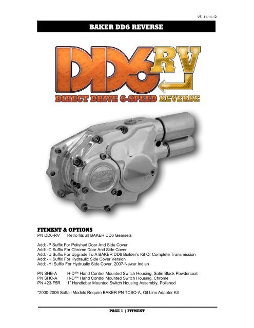
<strong>BAKER</strong> <strong>DD6</strong> <strong>REVERSE</strong><br />
V5, 11-14-12<br />
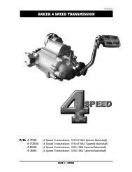
FITMENT & OPTIONS<br />
PN <strong>DD6</strong>-RV Retro fits all <strong>BAKER</strong> <strong>DD6</strong> Gearsets<br />
Add: -P Suffix For Polished Door And Side Cover<br />
Add: -C Suffix For Chrome Door And Side Cover<br />
Add: -U Suffix For Upgrade To A <strong>BAKER</strong> <strong>DD6</strong> Builder’s Kit Or Complete Transmission<br />
Add: -H Suffix For Hydraulic Side Cover Version<br />
Add: -HI Suffix For Hydrualic Side Cover, 2007-Newer Indian<br />
PN SHB-A<br />
PN SHC-A<br />
PN 423-F5R<br />
H-D Hand Control Mounted Switch Housing, Satin Black Powdercoat<br />
H-D Hand Control Mounted Switch Housing, Chrome<br />
1” Handlebar Mounted Switch Housing Assembly, Polished<br />
*2000-2006 Softail Models Require <strong>BAKER</strong> PN TCSO-A, Oil Line Adapter Kit<br />
PAGE 1 | FITMENT
<strong>BAKER</strong> <strong>DD6</strong> <strong>REVERSE</strong><br />
V5, 11-14-12<br />
TABLE OF CONTENTS<br />
1) Cover<br />
2) Table Of Contents<br />
3) Overview, Features, Getting Started, Tools Required<br />
4) Exploded View, <strong>DD6</strong>-RV Mechanical Side Cover Kit<br />
5) Exploded View Legend, <strong>DD6</strong>-RV Mechanical Side Cover Kit<br />
6) Exploded View, <strong>DD6</strong>-RV Hydraulic Side Cover Kit<br />
7) Exploded View Legend, <strong>DD6</strong>-RV Hydraulic Side Cover Kit<br />
8) Exploded View, <strong>DD6</strong>-RV Gearset<br />
9) Exploded View Legend, <strong>DD6</strong>-RV Gearset<br />
10) Disassembly<br />
11) Disassembly, <strong>DD6</strong>-RV Gearset Assembly<br />
12) <strong>DD6</strong>-RV Gearset Assembly<br />
13) <strong>DD6</strong>-RV Gearset Assembly<br />
14) <strong>DD6</strong>-RV Mechanical Side Cover Components<br />
15) <strong>DD6</strong>-RV Mechanical Side Cover Components<br />
16) <strong>DD6</strong>-RV Hydraulic Side Cover Components<br />
17) Wiring Harness/ 12V Ignition Wire Source<br />
18) Wiring Harness/ Factory Hand Control Mounted Switch Housing<br />
19) Wiring Harness/ 1” Handlebar Mounted Switch Housing<br />
20) Reverse Function Test<br />
21) Wiring Diagram<br />
22) Finish Line<br />
23) <strong>DD6</strong>-RV Usage Instructions<br />
24) Terms<br />
25) Disclaimer<br />
PAGE 2 | TABLE OF CONTENTS
V5, 11-14-12<br />
OVERVIEW<br />
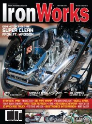
We introduced the F6R kit, or Factory 6-speed Reverse, for the 2007-later H-D ® 6-speed bike.<br />
The biggest advantage of the F6R is the ability to engage reverse from one switch in the handle<br />
bar area without the need to reach down near the hot exhaust. Minimal clutch modulation is<br />
required in reverse to launch the vehicle due to the short gear ratio. We finally got off our duff and<br />
are doing the same for the 1990-2006 5-speed bikes. We call it the <strong>DD6</strong>-RV or Direct Drive 6<br />
Speed Reverse. The contents in the <strong>DD6</strong>-RV kit are similar to the F6R; door, side cover,<br />
countershaft, reverse gear train and hardware. Existing gearset (except countershaft), shift<br />
system and top cover will be re-used with the <strong>DD6</strong>-RV installation. The <strong>DD6</strong>-RV will be<br />
appreciated by those with heavy GVW applications (trikes, side cars and trailers) or those with<br />
compromised leg mobility.<br />
FEATURES<br />
• Reverse selection controlled by aircraft grade shifting solenoid & bell crank assembly.<br />
Electronic reverse safety lock-out solenoid must first be energized with the provided handle<br />
bar or inner fairing mounted momentary toggle switch. Shift safely into reverse every time!<br />
• No need to use the starter motor for reverse maneuvers.<br />
• Includes ready to install solenoids and neutral safety switch wiring.<br />
• Reverse can only be selected when bike is in neutral by tying the solenoid function to the<br />
neutral switch on the transmission.<br />
• No case modifications required for reverse gearset installation.<br />
REQUIRED READING<br />
Regardless of the skill level or experience of the technician installing the <strong>DD6</strong>-RV Retro Fit Kit or<br />
<strong>DD6</strong>-RV Builder’s kit, it is highly recommended that a genuine H-D © Parts Catalog and Factory<br />
Service Manual be available for your model of motorcycle.<br />
TOOLS & PARTS<br />
• Common Hand Tools<br />
• Wire Cutters/ Strippers<br />
• Dielectric Grease<br />
• Heat Gun<br />
• Voltmeter<br />
• Split Bearing Press Tool<br />
(<strong>BAKER</strong> PN 483-<strong>DD6</strong>RV)<br />
• Torque Wrench: 3/8” & 1/2” Drive<br />
• 1 3/16” 6 pt Socket (Clutch Nut)<br />
• 1 1/2” 6 pt Socket (Motor Sprocket Nut)<br />
• 6” Calipers or 6” Machinists Scale<br />
• Access To An Oven<br />
• Primary Inner Race Service Kit<br />
(<strong>BAKER</strong> PN TOOLB-56)<br />
• 32oz Primary Fluid<br />
(Spectro PN R.GAPCL)<br />
• 22-24oz Transmssion Fluid<br />
(Spectro PN BD75140)<br />
<strong>BAKER</strong> <strong>DD6</strong> <strong>REVERSE</strong><br />
• ‘Blue’ & ‘Red’Thread Lock<br />
• ‘Silver’ Anti-Seize<br />
• Access To A 20 Ton Hydraulic Press<br />
• Primary Drive Service Kit (Gaskets,<br />
Seals, Lock Tabs, etc)<br />
HYDRAULIC VERSION PARTS<br />
• 11/16” Bore Master Cylinder Clutch<br />
Lever Assembly<br />
• 3/8-24” Thread Banjo Bolt<br />
• DOT 5 Silicone Based Brake Fluid<br />
(2007 & Newer Indian Models With<br />
Stock Controls Require Prestone, DOT<br />
4 Synthetic Brake Fluid)<br />
• 10mm Banjo Fitting (Angle Depends On<br />
Exhaust Bracket Style)<br />
<strong>DD6</strong>-RV BUILDER’S KIT OR COMPLETE BUILD TRANSMISSIONS<br />
Portions of these installation instructions do not apply to you if you bought a <strong>DD6</strong>-RV Builder’s kit<br />
or a complete transmission with <strong>DD6</strong>-RV upgrade, but the wiring installation notes, reverse<br />
function tests, and the general <strong>DD6</strong>-RV riding usage instructions do. If you have a builders kit,<br />
reference your Factory Service Manual for the instructions on how to swap out the main drive<br />
gear, main drive gear roller bearing and main drive gear roller bearing seal. As well as the<br />
installation of your secondary drive belt pulley or chain sprocket for torque specs.<br />
PAGE 3| OVERVIEW/ GETTING STARTED
<strong>BAKER</strong> <strong>DD6</strong> <strong>REVERSE</strong><br />
V5, 11-14-12<br />
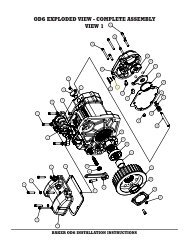
<strong>DD6</strong>-RV, MECHANICAL SIDE COVER, RETRO FIT KIT EXPLODED VIEW<br />
FIGURE 1<br />
PAGE 4| EXPLODED VIEW, <strong>DD6</strong>-RV MECHANICAL SIDE COVER RETRO FIT KIT
<strong>BAKER</strong> <strong>DD6</strong> <strong>REVERSE</strong><br />
V5, 11-14-12<br />
TAG PN QTY<br />
1 137RRRE 1<br />
DESCRIPTION<br />
Snap Ring, External Ø1.375” Shaft<br />
2 RV-7000 1 Driven Pinion Gear<br />
3 RV-7051 1 Retainer Nut, Mainshaft<br />
4 37089-84 1 Actuator Rod Assembly (2.625” Overall)<br />
5 3096-F5R 1 Ball Ramp, Inner<br />
6 987687 3 Ball Bearing, Ø3/8”<br />
7 3094-DSSC 1 Ferrule, Clutch Cable<br />
8 3196-F5R 1 Ball Ramp, Outer<br />
9 415-F5R 1 Gasket, Ball & Ramp Cover<br />
10 584-F5R 1 Ball & Ramp Cover<br />
11 25C62KCSS 3 ¼-20 x .625”, SHCS, SS<br />
12 73753 2 ¼-20 x .625”, BHCS, SS<br />
13 25C150KCSS/P 7 ¼-20 x 1.50”, SHCS, SS<br />
14 25C225KCSS/P 1 ¼-20 x 2.25”, SHCS, SS<br />
15 401-F5R 1 Side Cover, Mechanical<br />
16 51740-001 2 Drain & Oil Level Plug, 3/8-24<br />
17 414-F5R 1 Gasket, Side Cover<br />
18 51970S-008-01 1 Fill Plug, Zero Leak, ¾-16<br />
19 31F31KKCS 1 5/16-24 x 5/16” Set Screw, SS<br />
20 25R75PDP 1 ¼” x ¾” Pull Dowel<br />
21 HK1412 2 Needle Bearing, Split Idler Gear<br />
22 TRA-916 2 Thrust Washer, Split Idler Gear<br />
23 RV-7010 1 Split Idler Gear<br />
24 408-F5R 1 Jam Nut, Countershaft<br />
25 RV-7030 1 Dog Clutch<br />
26 RV-7020 1 Slider Gear<br />
27 168-F5R 1 Retainer Nut, Countershaft<br />
28 420-F5R 1 Solenoid Assembly, Lockout<br />
29 420S-F5R 1 Solenoid Assembly, Shifting<br />
30 LW 05611 0325S 1 Redux Return Spring<br />
31 404-F5R 1 Shift Fork, Reverse<br />
32 412-RV07 1 Fork Rod, Reverse<br />
33 407-F5R 1 Bearing Retainer Plate, Mainshaft<br />
34 24050 6 ¼-20 x .625”, BHCS, Black Oxide<br />
35 406-F5R 1 Bearing Retainer Plate, Countershaft<br />
36 6007 1 Roller Bearing, Mainshaft<br />
37 6205 1 Roller Bearing, Countershaft<br />
38 31C125KCSS/P 4 5/16-18 x 1.25”, SHCS, SS<br />
39 6100 4 5/16” AN Washer, SS<br />
40 26749 2 ¼”x ½” Alignment Dowel<br />
41 25C125KCSS/P 2 ¼-20 X 1.25”, SHCS, SS<br />
42 6099SS 2 ¼” AN Washer, SS<br />
43 132-<strong>DD6</strong>RV 1 Bearing Door, <strong>DD6</strong>-RV<br />
44 23207 1 ¼-20 X 1.25”, SHCS, Black Oxide<br />
45 LS2542 1 Thrust Washer, Countershaft<br />
46 413-<strong>DD6</strong>RV 1 Countershaft, <strong>DD6</strong>-RV<br />
47 35652-79B 1 Gasket, Bearing Door<br />
PAGE 5| EXPLODED VIEW LEGEND <strong>DD6</strong>-RV MECHANICAL SIDE COVER KIT
<strong>BAKER</strong> <strong>DD6</strong> <strong>REVERSE</strong><br />
V5, 11-14-12<br />
<strong>DD6</strong>-RV, HYDRAULIC SIDE COVER, RETRO FIT KIT EXPLODED VIEW<br />
FIGURE 2<br />
PAGE 6| EXPLODED VIEW, <strong>DD6</strong>-RV HYDRAULIC SIDE COVER RETRO FIT KIT
<strong>BAKER</strong> <strong>DD6</strong> <strong>REVERSE</strong><br />
V5, 11-14-12<br />
TAG PN QTY<br />
1 137RRRE 1<br />
DESCRIPTION<br />
Snap Ring, External Ø1.375” Shaft<br />
2 RV-7000 1 Driven Pinion Gear<br />
3 RV-7051 1 Retainer Nut, Mainshaft<br />
4 37089-84L 1 Actuator Rod Assembly (2.810” overall)<br />
5* 124-56L 1 Piston, Ø1.500” LSD<br />
5* 124-56L10 1 Piston, Ø1.000” 2007-newer Indian<br />
6* 66827 2 O-Ring, Buna, 1.5”OD Hydraulic Piston<br />
6* 9452K29 1 O-Ring, 1” OD, 3/4” ID Hydraulic Piston<br />
6* 9452K81 1 O-Ring, 1” OD, 13/16” ID Hydraulic Piston<br />
7 45-9404 1 Bleeder Valve<br />
8 25C150KCSS/P 7 ¼-20 x 1.50”, SHCS, SS<br />
9 25C225KCSS/P 1 ¼-20 x 2.25”, SHCS, SS<br />
10* 429-F5R 1 Side Cover, Ø1.5” Hydraulic Bore<br />
10* 429-F5R-I 1 Side Cover, Ø1.0” Hydraulic Bore<br />
11 51740-001 2 Drain & Oil Level Plug, 3/8-24<br />
12 414-F5R 1 Gasket, Side Cover<br />
13 51970S-008-01 1 Fill Plug, Zero Leak, ¾-16<br />
14 31F31KKCS 1 5/16-24 x 5/16” Set Screw, SS<br />
15 25R75PDP 1 ¼” x ¾” Pull Dowel<br />
16 HK1412 2 Needle Bearing, Split Idler Gear<br />
17 TRA-916 2 Thrust Washer, Split Idler Gear<br />
18 RV-7010 1 Split Idler Gear<br />
19 408-F5R 1 Jam Nut, Countershaft<br />
20 RV-7030 1 Dog Clutch<br />
21 RV-7020 1 Slider Gear<br />
22 168-F5R 1 Retainer Nut, Countershaft<br />
23 420-F5R 1 Solenoid Assembly, Lockout<br />
24 420S-F5R 1 Solenoid Assembly, Shifting<br />
25 LW 05611 0325S 1 Redux Return Spring<br />
26 404-F5R 1 Shift Fork, Reverse<br />
27 412-RV07 1 Fork Rod, Reverse<br />
28 407-F5R 1 Bearing Retainer Plate, Mainshaft<br />
29 24050 6 ¼-20 x .625”, BHCS, Black Oxide<br />
30 406-F5R 1 Bearing Retainer Plate, Countershaft<br />
31 6007 1 Roller Bearing, Mainshaft<br />
32 6205 1 Roller Bearing, Countershaft<br />
33 31C125KCSS/P 4 5/16-18 x 1.25”, SHCS, SS<br />
34 6100 4 5/16” AN Washer, SS<br />
35 26749 2 ¼”x ½” Alignment Dowel<br />
36 25C125KCSS/P 2 ¼-20 X 1.25”, SHCS, SS<br />
37 6099SS 2 ¼” AN Washer, SS<br />
38 132-<strong>DD6</strong>RV 1 Bearing Door, <strong>DD6</strong>-RV<br />
39 23207 1 ¼-20 X 1.25”, SHCS, Black Oxide<br />
40 LS2542 1 Thrust Washer, Countershaft<br />
45 413-<strong>DD6</strong>RV 1 Countershaft, <strong>DD6</strong>-RV<br />
46 35652-79B 1 Gasket, Bearing Door<br />
PAGE 7| EXPLODED VIEW LEGEND <strong>DD6</strong>-RV MECHANICAL SIDE COVER KIT
<strong>BAKER</strong> <strong>DD6</strong> <strong>REVERSE</strong><br />
<strong>DD6</strong>-RV BUILDER’S KIT GEARSET EXPLODED VIEW<br />
V5, 11-14-12<br />
FIGURE 3<br />
PAGE 8| EXPLODED VIEW <strong>DD6</strong>-RV BUILDER’S KIT
<strong>BAKER</strong> <strong>DD6</strong> <strong>REVERSE</strong><br />
V5, 11-14-12<br />
TAG PN QTY DESCRIPTION<br />
1* 555-56B-A 1 Shifter Pawl Assembly (EVO Models)<br />
1* 555-56L-A 1 Shifter Pawl Assembly (Twin Cam Models)<br />
2 12045 1 Seal, Shifter Pawl<br />
3 6947HW 1 Washer, Shifter Pawl<br />
4 68010 1 Snap Ring, External, Ø7/16”<br />
5 70813 1 Jam Nut, Eccentric Screw 7/16-14<br />
6 152-56A 1 Eccentric Shifter Pawl Adjuster<br />
7 <strong>DD6</strong>-2C-1 1 2nd Gear, Countershaft<br />
8 8876A 5 Split Cage Needle Bearing<br />
9 6003B 5 Thrust Washer, Gearset<br />
10 11067A 6 Snap Ring, External, Gearset<br />
11 <strong>DD6</strong>-3C-1 1 3rd Gear Counter Shaft<br />
12* <strong>DD6</strong>-1C-1 1 1st Gear C/S, (3.24 Ratio)<br />
12* <strong>DD6</strong>-1C-2.94 1 1st Gear C/S, (2.94 Ratio)<br />
13 <strong>DD6</strong>-4C 1 4th Gear, Countershaft<br />
14 <strong>DD6</strong>-5C 1 5th Gear, Countershaft<br />
15 124E-<strong>DD6</strong>A 1 Shift Drum Assembly<br />
16 23207 4 ¼-20 x 1.5” SHCS, Black Oxide<br />
17 33001 4 Washer, #10 Plain<br />
18 174-<strong>DD6</strong> 1 Shift Fork, 4th-5th Mainshaft<br />
19 173-<strong>DD6</strong> 1 Shift Fork, 3rd Gear Countershaft<br />
20 172-<strong>DD6</strong> 1 Shift Fork, 2nd Gear Mainshaft<br />
21 122-6R-FF 1 Fork Rod<br />
22* <strong>DD6</strong>-MS 1 Mainshaft (3.24 1st Gear)<br />
22* <strong>DD6</strong>-MS-2.94 1 Mainshaft (2.94 1stGear)<br />
23 34091-85X 1 Inner Primary Race<br />
24 12035B 1 Oil Seal, Main Drive Gear<br />
25 HK2520 2 Caged Needle Bearing, Main Drive Gear<br />
26 33344-94S 1 Pulley Spacer<br />
27 12067B 1 Oil Seal, Roller Bearing<br />
28 1302-334PP 1 Snap Ring, Internal, Beveled, Ø3 11/32<br />
29 11165A 1 Quad Seal<br />
30 6209 1 Roller Bearing, Main Drive Gear<br />
31 <strong>DD6</strong>-6M-1 1 Main Drive Gear, 6th Gear<br />
32 <strong>DD6</strong>-2M-1 1 2nd Gear, Mainshaft<br />
33 <strong>DD6</strong>-3M-1 1 3rd Gear, Mainshaft<br />
34 <strong>DD6</strong>-4M-1 1 4th Gear, Mainshaft<br />
35 <strong>DD6</strong>-4C5-1 1 Dog Clutch, 4 th -5 th Gear<br />
36 <strong>DD6</strong>-5M-1 1 5th Gear, Mainshaft<br />
37 TWD1423 1 Thrust Washer, Bearing Door .125<br />
PAGE 9| EXPLODED VIEW <strong>DD6</strong>-RV BUILDER’S KIT LEGEND
<strong>BAKER</strong> <strong>DD6</strong> <strong>REVERSE</strong><br />
V5, 11-14-12<br />
DISASSEMBLY<br />
SIMILAR TO ANY OTHER DRIVETRAIN RELATED PROJECT, THE FIRST STEP<br />
THAT YOU WANT TO TAKE IS TO REMOVE THE SEAT AND DISCONNECT THE<br />
BATTERY FOR YOUR OWN SAFETY. NOW IS ALSO A GOOD TIME TO DRAIN THE<br />
PRIMARY AND TRANSMISSION FLUID. FOR LOCATIONS OF APPLICABLE DRAIN<br />
PLUGS, CHECK YOUR SERVICE MANUAL.<br />
1) While referencing your Factory Service Manual (section 7), follow the gearset removal<br />
procedure. If you are installing the <strong>DD6</strong>-RV Retro Fit Kit on your <strong>BAKER</strong> <strong>DD6</strong>, you do not<br />
need to remove your main drive gear, but do need to remove the secondary drive<br />
pulley/sprocket in order to install the provided fork rod (Tag 21, Figure 3) during the <strong>DD6</strong>-RV<br />
gearset install.<br />
2) With the gearset still bolted in the transmission case, but no shift system, slide the gears by<br />
hand to lock the transmission in two gears and remove the shaft nuts with a 1 1/16” socket.<br />
3) With the gearset out of the motorcycle, remove 2 nd gear (Tag 32, Figure 3), the snap ring<br />
(Tag 10, Figure 3) and thrust washer (Tag 9, Figure 3) to be able to slide 3 rd gear (Tag 33,<br />
Figure 3) down the mainshaft. Care must be taken to ensure that no gear teeth are damaged<br />
during the disassembly process as you are re-using all of your gears, except the<br />
countershaft. When removing the split cage needle bearings, only open them enough to slide<br />
up the shaft, rather than pulling them off to the side. This will help prevent cracks to the<br />
plastic cage of the bearings. Press the countershaft out of the bearing door. Then press the<br />
mainshaft out.<br />
4) Clean the transmission case out with brake cleaner or another suitable cleaner at this time<br />
and inspect it for issues that may affect the installation of the gearset or cause leaks down<br />
the road. Including, but not limited too, bad threads in the case, gouges in the gaskets<br />
surfaces, residual build up of thread lock and that the case bearings spin freely and smoothly.<br />
5) Set the mainshaft aside and start disassembling the<br />
countershaft by sliding 3rd gear (Tag 11, Figure 3)<br />
FIGURE 4<br />
into 2nd gear (Tag 7, Figure 3) to gain the room to<br />
reach the snap ring (Tag 10, Figure 3) holding 1st<br />
gear (Tag 7, Figure 3) in place. You need to do this<br />
to be able to get a press tool around the shaft to<br />
press 4th (PN <strong>DD6</strong>-4C-1) and 5th (Tag 14, Figure 3)<br />
gear off.<br />
6) Slide the snap ring (Tag 10, Figure 3), thrust washer<br />
(Tag 9, Figure 3) and 1st gear (Tag 12, Figure 3)<br />
towards 3 rd gear (Tag 11, Figure 3). (See Figure 5)<br />
7) Slide the <strong>BAKER</strong> <strong>DD6</strong>-RV Press Tool (PN 483-<br />
FIGURE 5<br />
<strong>DD6</strong>RV) around the shaft and bolt the halves<br />
together. Torque the bolts to 20 ft-lbs. At the same<br />
time, press off 4th (Tag 13, Figure 3) and 5 th (Tag<br />
14, Figure 3) gears. Remove the rest of the gears<br />
from the countershaft at this time.<br />
8) With the gears laid out, inspect everything; gear<br />
teeth, dog teeth and split cage needle bearings for<br />
any cracks, excessive wear, heat spots or evidence<br />
of being run low on oil or without oil.<br />
IF THERE IS ANY DOUBT ABOUT THE ABILITY TO RE USE ANY OF THE<br />
SPLIT CAGE NEEDLE BEARINGS AFTER INSPECTION, REPLACE THEM.<br />
PAGE 10| DISASSEMBLY
<strong>BAKER</strong> <strong>DD6</strong> <strong>REVERSE</strong><br />
V5, 11-14-12<br />
9) Install the provided main drive gear oil seal (Tag 24, Figure 3), roller bearing seal (Tag 27,<br />
Figure 3) and quad seal (Tag 29, Figure 3) at this time. With the old seal of out the main<br />
drive, check to make the outboard most needle bearing has not ‘walked’ towards the<br />
transmission. If so, reference your Factory Service Manual in order to replace it with a new<br />
bearings (Tag 25, Figure 3)<br />
GEARSET ASSEMBLY, <strong>DD6</strong>-RV RETRO FIT KIT<br />
1) Preheat an oven to 450° and place 4th (Tag 13, Figure 3) and 5th (Tag 14, Figure 3) gears in<br />
the oven for 25-30 minutes in preparation for pressing them on the provided <strong>DD6</strong>-RV<br />
countershaft. (Tag 46, Figure 1 or Tag 45, Figure 2)<br />
DO NOT HEAT THE GEARS WITH A TORCH, ANY OTHER FORM OF DIRECT HEAT,<br />
OR ANY NON THERMOSTATICALLY CONTROLLED OVEN AS YOU WILL DAMAGE<br />
THE HEAT TREAT ON THE SURFACE OF THE GEARS. DO NOT PRESS ON THE<br />
GEARS AT ROOM TEMPERATURE. THE GEARS ARE DESIGNED WITH A LARGE<br />
AMOUNT OF PRESS TO HOLD THEM IN PLACE UNDER LOAD. PRESSING THEM<br />
ON COLD WILL INDUCE STRESS RISERS IN THE GEAR AND/ OR THE<br />
COUNTERSHAFT. THIS WILL CAUSE PREMATURE WEAR RELATED ISSUES THAT<br />
WILL NOT BE COVERED UNDER WARRANTY DUE TO IMPROPER INSTALLATION<br />
PROCEDURE.<br />
2) Provided are six gearset snap rings (Tag 10, Figure 3) Five are needed and one is extra as<br />
they are easy to overstretch. Pre-lube all of the split cage needle bearings with new<br />
transmission fluid before installing them.<br />
TAKE CARE TO ONLY OPEN UP THE GEARSET SNAP RINGS ENOUGH TO SLIDE<br />
THEM DOWN THE SPLINES INTO THEIR PROPER POSITION ON THE SHAFTS.<br />
3) Assemble the countershaft gear cluster while referencing the gearset exploded view and<br />
legend on pages 6 and 7. With 1st, 2nd and 3rd gear on the shaft, the snap rings securely in<br />
place and 4 th and 5 th gear properly heated. Press the gears on the shaft in the proper<br />
orientation (See Figure 3) and make sure to fully seat them on the shaft for proper gear<br />
alignment in the transmission.<br />
4) Slide the provided countershaft thrust washer (Tag 45, Figure 1 or Tag 40, Figure 2) onto the<br />
countershaft in preparation for pressing the shafts into the bearing door.<br />
5) With 3rd gear (Tag 33, Figure 3) on the mainshaft, but not held in place with a snap ring, slide<br />
the mainshaft into the bearing door. Make sure that you re use the hardened mainshaft thrust<br />
washer, (Tag 37, Figure 3) on the end of the mainshaft. While you press the mainshaft into<br />
the door bearing (Tag 36, Figure 1 or Tag 31, Figure 2), make sure to fully support the inner<br />
race of the bearing to maintain its integrity. Fully seat the mainshaft in the door against the<br />
thrust washer.<br />
6) Press the countershaft gear cluster into the bearing door making sure to fully support the<br />
inner race of the bearing (Tag 37, Figure 1 or Tag 32, Figure 2) to maintain its integrity.<br />
Support 3rd gear (Tag 33, Figure 3) with your hand to make sure it is meshing with 3rd gear<br />
(Tag 11, Figure 3) on the countershaft.<br />
7) With both shafts pressed into the bearing door, and fully ‘bottomed out’ on their applicable<br />
thrust washers, install the thrust washer (Tag 9, Figure 3) and snap ring (Tag 10, Figure 3) on<br />
the mainshaft to hold 3rd gear (Tag 33, Figure 3) in place. Slide 2nd gear (Tag 32, Figure 3)<br />
onto the mainshaft at this time.<br />
PAGE 11| DISASSEMBLY/ <strong>DD6</strong>-RV GEARSET ASSEMBLY
<strong>BAKER</strong> <strong>DD6</strong> <strong>REVERSE</strong><br />
V5, 11-14-12<br />
8) Hang the provided door gasket (Tag 47, Figure 1 or Tag 46, Figure 2) on the transmission<br />
case door pins.<br />
9) With the gearset assembled, wrap the clutch nut threads and splines on the mainshaft with<br />
electrical tape before sliding the gearset into the case to protect the new oil seal (Tag 24,<br />
Figure 3) in the main drive gear.<br />
10) Depending on the brand of exhaust that you have on your motorcycle and the subsequent<br />
mounting brackets, now is a good time to do a ‘dry fit’ of the exhaust bracket and side cover<br />
(Tag 15, Figure 1 ‘Mechanical’ or Tag 10, Figure 2 ‘Hydraulic’), with side cover gasket (Tag<br />
17, Figure 1 or Tag 12, Figure 2) to determine if any modifications need to be made to your<br />
exhaust bracket. Also install the crush washers, banjo fitting and hydraulic clutch line at this<br />
time (on hydraulic side cover models) to assess the clearance for those parts as well. (When<br />
satisfied with the exhaust bracket mounting proceed with ‘blue’ thread lock to install the four<br />
5/16-18 x 1.25” door bolts (Tag 38, Figure 1 or Tag 33, Figure 2), with washers (Tag 39,<br />
Figure 1 or Tag 34, Figure 2) and three, ¼-20 x 1.25” door bolts (Tag 41, Figure 1 or Tag 36,<br />
Figure 2 & Tag 44, Figure 1 or Tag 39, Figure 2) with washers (Tag 42, Figure 1 or Tag 37,<br />
Figure 2) at this time. Torque the 5/16” bolts to 220 in-lbs and the 1/4” bolts to 130 in-lbs in<br />
the order shown in figure 5.<br />
FIGURE 6<br />
11) Slide the gears in the transmission to lock it in two gears and remove the countershaft<br />
retainer plate (Tag 35, Figure 1 or Tag 30, Figure 2) to ensure full socket contact with the<br />
retainer nut on the countershaft. While using ‘red’ thread lock, torque the countershaft (Tag<br />
27, Figure 1 or Tag 22, Figure 2 ‘snout’ of nut facing door bearing) and mainshaft (Tag 3,<br />
Figure 1 or Tag 3, Figure 2) nuts to 45-50 ft-lbs.<br />
DO NOT USE AN IMPACT GUN TO TIGHTEN EITHER SHAFT RETAINING NUT AS<br />
YOU RISK DAMAGE TO THE NUTS AND/OR SHAFTS BY DOING SO.<br />
PAGE 12| <strong>DD6</strong>-RV GEARSET ASSEMBLY
<strong>BAKER</strong> <strong>DD6</strong> <strong>REVERSE</strong><br />
V5, 11-14-12<br />
12) Install the countershaft retainer plate using<br />
‘red’ thread lock and torque each ¼-20 x<br />
.625” button head (Tag 34, Figure 1 or Tag<br />
29, Figure 2) to 130 in-lbs.<br />
13) Install the shift system at this point, while<br />
referencing the exploded view (Figure 3) on<br />
page 8. Install the provided fork rod (Tag 21,<br />
Figure 3) from the primary side of the<br />
motorcycle.<br />
14) Torque the four pillow block bolts (Tag 16,<br />
Figure 3) to 130 in-lbs using ‘blue’ thread<br />
lock. Adjust the shifter pawl over the drum<br />
pins to +-.010” with the transmission in 3 rd<br />
gear and torque the eccentric adjuster jam<br />
nut (Tag 5, Figure 3) to 20 ft-lbs with ‘blue’<br />
thread lock.<br />
15) Run the transmission through all the gears<br />
multiples time before proceeding with the<br />
FIGURE 7<br />
**INSTALLATION PICTURES TAKEN USING THE<br />
<strong>BAKER</strong> 1999 ROAD KING, WHICH HAS<br />
CUSTOM EXHAUST AND THEREFORE HAS NO<br />
EXHAUST BRACKET ON THE FACE OF THE<br />
BEARING DOOR<br />
<strong>DD6</strong>-RV reverse geartrain installation to ensure the gearset was correctly assembled.<br />
16) With correct transmission function validated, install the secondary drive pulley/ sprocket and<br />
belt/ chain at this time while referencing your Factory Service Manual.<br />
17) Install the reverse side cover components while referencing the exploded views (Figure 1 or<br />
Figure 2). Remember to place a thrust washer (Tag 22, Figure 1 or Tag 17, Figure 2) behind<br />
the split idler gear (Tag 23, Figure 1 or Tag 18, Figure 2). Install slider gear (Tag 26, Figure 1<br />
or Tag 21, Figure 2) and dog clutch (Tag 25, Figure 1 or Tag 20, Figure 2). Torque the<br />
countershaft jam nut (Tag 24, Figure 1 or Tag 19, Figure 2) to 33-35 ft-lbs using ‘red’ thread<br />
lock.<br />
18) Slide the shift fork (Tag 31, Figure 1 or Tag 26, Figure 2) onto the slider gear and rotate it up<br />
into place to slide the provided fork rod (Tag 32, Figure 1 or Tag 27, Figure 2) into the bore in<br />
the bearing door. Fully seat the fork rod with your hand, but do not hit it with a hammer, you<br />
do not need to do so and will struggle to remove it in the future by binding it in the bearing<br />
door. Place the redux return spring (Tag 30, Figure 1 or Tag 25, Figure 2) on the fork rod.<br />
Place the other provided thrust washer (Tag 22, Figure 1 or Tag 17, Figure 2) on the<br />
outboard pinion of the split idler gear. Hang the side cover gasket (Tag 17, Figure 1 or Tag<br />
12, Figure 2) on the door at this time as well.<br />
19) Re-use and install your center clutch rod and slide the provided clutch push rod assembly<br />
(Tag 4, Figure 1 ‘Mechanical’ or Tag 4, Figure 2 ‘Hydraulic’) into the mainshaft<br />
20) Install the top cover with the provided neutral switch (PN 21-438)<br />
FIGURE<br />
per your<br />
8<br />
Factory Service<br />
Manual at this time. Torque the neutral switch to 135 in-lbs. Double check that the<br />
transmission is in neutral and that you have proper neutral switch function by using a<br />
voltmeter to check for continuity. FIGURE 7<br />
PAGE 13| <strong>DD6</strong>-RV GEARSET ASSEMBLY
<strong>BAKER</strong> <strong>DD6</strong> <strong>REVERSE</strong><br />
V5, 11-14-12<br />
<strong>DD6</strong>-RV MECHANICAL SIDE COVER COMPONENTS INSTALLATION<br />
PN 420S-F5R, Shifting Solenoid Assembly<br />
TAG PN QTY DESCRIPTION<br />
1 S-22-150 1 R22x22 12V, Pull Solenoid<br />
1 410-F5R 1 Shifting Solenoid Cover<br />
2 OR568119 1 O-ring, 1.00” ID<br />
3 LP 032N 01 S316 1 Return Spring, .720” ID<br />
4 PB26165 1 Spring Seat, .625” ID<br />
5 WSM-62 1 Spiral Snap Ring, .625”<br />
6 26735 1 3/16” X 1/2” Solid Dowel<br />
7 185-F5R 1 Shifting Plunger<br />
8 409-F5R 1 Shifting Bell Crank<br />
PN 420-F5R, Reverse Lock Out Solenoid Assembly<br />
TAG PN QTY DESCRIPTION<br />
9 S-06231 1 1 R16x16,12V, Pull Solenoid<br />
10 66827 1 O-ring, .750” ID<br />
11 LP 026K 01 S316 1 Return Spring, .475” ID<br />
12 716NWSFS 1 Spring Seat, .440” ID<br />
13 91665A350 1 Spiral Snap Ring, .440” ID<br />
14 182-F5R 1 Lockout Plunger<br />
FIGURE 9<br />
1) Apply anti-seize to the threads and install the mechanical clutch cable into the side cover.<br />
Check to make sure the clutch cable o-ring is in good working condition, if it is not, replace it<br />
at this time.<br />
DO NOT OVER TIGHTEN THE CLUTCH CABLE FITTING OR IT WILL BREAK OFF<br />
IN THE SIDE COVER.<br />
2) Insert the plunger (Tag 7, Figure 9) with bell crank installed on it in the solenoid port from the<br />
inside of the side cover without the washer or spring. Refer to Figure 10 for orientation of the<br />
bell crank when installed. Slide the washer (Tag 4, Figure 9) and spring (Tag 3, Figure 9)<br />
over the plunger from the solenoid port side.<br />
3) Apply anti-seize to the threads on the solenoids and thread them in by hand with the side<br />
cover off of the motorcycle. Install the lockout solenoid (PN 420-F5R) as a complete<br />
assembly as shown in Figure 9.<br />
DO NOT TIGHTEN THE SOLENOIDS WITH ANYTHING OTHER THAN YOUR<br />
HANDS. RUN THE SOLENOIDS ALL THE WAY IN UNTIL THEY BOTTOM OUT IN<br />
THE SIDE COVER. TAKE CARE WHEN THREADING THE SOLENOIDS IN TO NOT<br />
GET THE WIRES TWISTED AT THE POINT THEY COME OUT THE BACK OF THE<br />
SOLENOID. ANYTIME THE SOLENOIDS NEED TO BE REMOVED IN THE FUTURE<br />
FOR REGULAR MOTORCYCLE SERVICE, MAKE SURE THEY ARE UNPLUGGED SO<br />
YOU ARE NOT PINCHING THE WIRES CAUSING A POSSIBLE FAILURE POINT.<br />
PAGE 14| <strong>DD6</strong>-RV MECHANICAL SIDE COVER COMPONENTS
<strong>BAKER</strong> <strong>DD6</strong> <strong>REVERSE</strong><br />
V5, 11-14-12<br />
4) With the solenoids installed slide the pull dowel (Tag 20, Figure 1 or Tag 15, Figure 2) part of<br />
the way into the side cover to hold bell crank out of the way while installing the side cover on<br />
the bearing door. Make sure to have the threaded end (8-32 thread) of the dowel facing<br />
up when you install it.<br />
5) Grab two of the side cover bolts and thread them into the door to hold the side cover in place<br />
during installation of the bell crank (Tag 8, Figure 9) on to the reverse shift fork (Tag 26,<br />
Figure 1 or Tag 31, Figure 2)<br />
6) Remove the pull dowel and with a pick or a small screwdriver, slide the bell crank slot over<br />
the fork pin. Final installation should like Figure 10. Reinstall the pull dowel. A little wiggling of<br />
the bell crank may be necessary to line up the pivot hole with the pull dowel. Install the set<br />
screw (Tag 19, Figure 1 or Tag 14, Figure 2) with ‘blue’ thread lock and screw in until it is<br />
flush with the top of the side cover.<br />
7) Remove the ball and ramp cover (Tag 10, Figure 1) and gasket (Tag 9, Figure 1).<br />
8) Lay the inner ball ramp (Tag 5, Figure 1) on a workbench and fill each of the three pockets<br />
with enough axle grease to hold the ball bearings (Tag 6, Figure 1) in place during assembly.<br />
Place the ball bearings in the greased pockets and then the outer ball ramp (Tag 8, Figure 1)<br />
on top. While making sure to hold the ramps together, slide them into the side cover. Align<br />
the tab on the outer ramp with the corresponding pocket in the side cover. The cable<br />
attachment boss of the inner ramp should be pointing towards the rear of the motorcycle<br />
when installed.<br />
9) With all of the adjustment out of the clutch cable (full slack) slide the clutch cable through the<br />
inner ball ramp enough that you can then slide the ferrule (Tag 7, Figure 1) over the end of<br />
the cable. Carefully pull on the clutch lever enough to get the ferrule seated in the ball ramp<br />
pocket.<br />
10) Place the ball and ramp cover (Tag 10, Figure 1) and gasket (Tag 9, Figure 1) back on the<br />
side cover and install the top bolt (Tag 11, Figure 1) and one of the bottom bolts, (Tag 12,<br />
Figure 1) to hold the ball and ramp assembly in place during installation of the F5R solenoid<br />
wiring harness and reverse function testing. Skip to page 15 for wiring harness installation.<br />
FIGURE 10<br />
PAGE 15|<strong>DD6</strong>-RV MECHANICAL SIDE COVER COMPONENTS
<strong>BAKER</strong> <strong>DD6</strong> <strong>REVERSE</strong><br />
V5, 11-14-12<br />
<strong>DD6</strong>-RV HYDRAULIC SIDE COVER COMPONENTS INSTALLATION<br />
1) Insert the plunger (Tag 8, Figure 9) with bell crank installed on it in the solenoid port from the<br />
inside of the side cover without the washer or spring. Refer to Figure 10 for orientation of the<br />
bell crank when installed. Slide the washer (Tag 4, Figure 9) and spring (Tag 3, Figure 9)<br />
over the plunger from the solenoid port side.<br />
2) Apply anti-seize to the threads on the solenoids and thread them in by hand with the side<br />
cover off of the motorcycle. Install the lockout solenoid (PN 420-F5R) as a complete<br />
assembly as shown in Figure 9.<br />
DO NOT TIGHTEN THE SOLENOIDS WITH ANYTHING OTHER THAN YOUR<br />
HANDS. RUN THE SOLENOIDS ALL THE WAY IN UNTIL THEY BOTTOM OUT IN<br />
THE SIDE COVER. TAKE CARE WHEN THREADING THE SOLENOIDS IN TO NOT<br />
GET THE WIRES TWISTED AT THE POINT THEY COME OUT THE BACK OF THE<br />
SOLENOID. ANYTIME THE SOLENOIDS NEED TO BE REMOVED IN THE FUTURE<br />
FOR REGULAR MOTORCYCLE SERVICE, MAKE SURE THEY ARE UNPLUGGED SO<br />
YOU ARE NOT PINCHING THE WIRES CAUSING A POSSIBLE FAILURE POINT.<br />
3) With the solenoids installed slide the pull dowel (Tag 20, Figure 1 or Tag 15, Figure 2) part of<br />
the way into the side cover to hold bell crank out of the way while installing the side cover on<br />
the bearing door. Make sure to have the threaded end (8-32 thread) of the dowel facing<br />
up when you install it.<br />
4) Grab two of the side cover bolts and thread them into the door to hold the side cover in place<br />
during installation of the bell crank (Tag 8, Figure 9) on to the reverse shift fork (Tag 26,<br />
Figure 1 or Tag 31, Figure 2)<br />
5) Remove the pull dowel and with a pick or a small screwdriver, slide the bell crank slot over<br />
the fork pin. Final installation should like Figure 10. Reinstall the pull dowel. A little wiggling of<br />
the bell crank may be necessary to line up the pivot hole with the pull dowel. Install the set<br />
screw (Tag 19, Figure 1 or Tag 14, Figure 2) with ‘blue’ thread lock and screw in until it is<br />
flush with the top of the side cover.<br />
6) Install two crush washers, banjo fitting (3/8-24 thread) and hydraulic line at this time. Hold off<br />
fully tightening the banjo bolt and line fittings until the side cover is fully installed.<br />
PAGE 16| <strong>DD6</strong>-RV HYDRAULIC SIDE COVER COMPONENTS
<strong>BAKER</strong> <strong>DD6</strong> <strong>REVERSE</strong><br />
V5, 11-14-12<br />
<strong>DD6</strong>-RV WIRING HARNESS INSTALLATION<br />
Based on the year and model of your motorcycle there are 2 different configurations of the same<br />
basic wiring harness used, as laid out in Figure 17 on page 21. The following steps will lay out, in<br />
detail, how to install the various wires and switches.<br />
IGNITION WIRE, 12V POWER SOURCE<br />
1) While referencing your Factory Service Manual, trace down the main ignition wire on your<br />
motorcycle as shown in Figure 11. Cut the wire a few inches before it splits off to enter the<br />
main fuse block and strip the insulation back 1/4” on each wire. You are going to splice in the<br />
power wire for the reverse shifting and safety toggles switches here. Take care to install the<br />
provided inline fuse holder in such a manner that it easily accessible should you ever need to<br />
change the standard size 20A blade fuse.<br />
2) The provided step down, heat shrink butt connector (PN SCB-646) needs to be crimped in<br />
the same manner as a standard butt connector but also has the added feature of containing<br />
heat activated glue to further join the wires together and provide a weather tight seal. Twist<br />
the keyed ignition side wire together with the bare wire end of the provided toggle switch to<br />
12V power wire assembly (PN 428-F5R) and slide into the plain end of the PN SCB-646<br />
splice butt connector. Crimp the connector to the two wires, making sure that you have them<br />
securely in place. Insert the fuse block side ignition wire into the striped end of the connector<br />
and crimp it in place. Using a heat gun, shrink the connector to the wires.<br />
PROVIDED WIRE<br />
PN 428-F5R<br />
KEYED IGNITION<br />
WIRE SIDE OF<br />
CONNECTION<br />
MAIN FUSE BLOCK<br />
SIDE OF<br />
CONNECTION<br />
FIGURE 11<br />
3) Run the wires up to the handlebars via the back bone, under the gas tank and by the right<br />
side of the neck in preparation for installing the switch housing that you ordered. Take care to<br />
make sure the wires are securely in place to prevent, chaffing, binding or pinching.<br />
PAGE 17| <strong>DD6</strong>-RV WIRING/ 12V POWER SOURCE
<strong>BAKER</strong> <strong>DD6</strong> <strong>REVERSE</strong><br />
V5, 11-14-12<br />
H-D BRAKE LEVER PERCH MOUNTED SWITCH HOUSING<br />
1) If you choose either switch housing assembly, Satin Black (PN SHB-A) or Chrome (PN SHC-<br />
A) installation is the same. Both units have the Toggle Switches (PN 7200018, Momentary,<br />
Screw Terminals & PN 73185, ON-OFF, Screw Terminals) installed in them and the rubber<br />
boots are snug. Remove the factory handle bar inner clamp, reusing the factory torx head<br />
bolts, & washers, with ‘blue’ thread lock, torque to 120 in-lbs. Set the factory clamp aside.<br />
2) Locate the solenoid toggle switch wires (PN 424Y-F5R & PN 424G-F5R) and run them up<br />
through the battery box from the transmission, up the back bone under the gas tank and by<br />
the neck to the toggle switches Take care to make sure the wires are securely in place to<br />
prevent, chaffing, binding or pinching. Before sliding all 4 wires into the switch housing (PN<br />
422-F5RB), slide the provided protective sleeve over the wires. (refer to figure 17)<br />
3) Arrange the wires as shown in Figure 12, by matching up the color coded wires to the color<br />
marked plugs. The wires are a tight fit, and no different than dealing with the factory switch<br />
housing for the RUN/OFF & START buttons, care needs to be taken to prevent shorting out<br />
the wires by crimping them in the housing, or chaffing on each other. After installing them on<br />
the toggle switches, wrap the terminals and wires with electrical tape. Gently slide the 4 wires<br />
back through the housing and install the two provided 10-24x ½” Stainless Bolts. (PN<br />
10C50KCSS) Torque to 85 in-lbs with ‘blue’ thread lock.<br />
4) While referencing your Factory Service Manual, locate the neutral switch wires and cut off the<br />
factory end(s) at the neutral switch on the transmission top cover. Slide on the provided 1/8”<br />
dia heat shrink and eyelet(s) (PN A-321-10), crimp the eyelets in place, and slide the heat<br />
shrink over the crimp. Shrink the tubing with a heat gun.<br />
5) Install the neutral switch to solenoid ground wire (PN 426-F5R) as shown in Figure 17. Also<br />
install the other neutral switch terminal wire at this time as shown in Figure 17. (Model year<br />
dependent).<br />
FIGURE 12 FIGURE 13<br />
PAGE 18| <strong>DD6</strong>-RV WIRING/ FACTORY HAND CONTROL MOUNTED SWITCH HOUSING
<strong>BAKER</strong> <strong>DD6</strong> <strong>REVERSE</strong><br />
V5, 11-14-12<br />
HANDLEBAR MOUNTED SWITCH HOUSING<br />
1) If you ordered a handlebar mounted switch housing assembly (PN 423-F5R) it comes with<br />
the toggle switches already installed and ready to go. All you have to do is find a spot on your<br />
1” diameter handlebars that will allow the<br />
housing to fully clamp to the bars. This<br />
spot will need to clear the gas tank with<br />
the bars at full lock in either direction and<br />
that the wires will not get pinched or<br />
experience chaffing from the bars turning.<br />
2) Locate the solenoid toggle switch wires<br />
(PN 424Y-F5R & 424G-F5R) and run<br />
them up through the battery box from the<br />
transmission, up the back bone under the<br />
gas tank and by the neck to the toggle<br />
switches Take care to make sure the<br />
wires are securely in place to prevent,<br />
chaffing, binding or pinching. (refer to<br />
figure 17)<br />
FIGURE 13<br />
3) Replace the #6 stud ring terminals with 4pcs of the provided (PN A-850) female blade<br />
terminals; make sure to slide on the provided Shrink tube to each wire before crimping the<br />
terminals. Match the color coded wires to the color coded terminals on the switches.<br />
4) Torque the four 10-24 x 1/2” SHCS, SS (PN 10C50KCSS) screws to 85 in-lbs in a ‘X’ pattern<br />
using ‘blue’ thread lock to ensure the housing and switches stay in place on the handlebars.<br />
FIGURE 14<br />
PAGE 19| <strong>DD6</strong>-RV WIRING/ HANDLE BAR MOUNTED WIRING HARNESS
<strong>BAKER</strong> <strong>DD6</strong> <strong>REVERSE</strong><br />
V5, 11-14-12<br />
<strong>REVERSE</strong> FUNCTION TEST<br />
1) With all of the wires hooked up and double checked against Figure 15, you are ready to do a<br />
reverse functionality test. Temporarily hook up the battery. With the bike ignition on, and the<br />
bike in neutral, the first check is that the Safety Switch (the momentary style switch) activates<br />
the Safety solenoid. You will hear an audible ‘click’ of the solenoid. This let’s you know that<br />
you have the wires hooked up correctly. If you do not hear an audible click then, you need to<br />
double check that the safety (smaller diameter, lower solenoid) is hooked up to the<br />
momentary switch.<br />
2) With the bike in neutral and the back tire off of the lift or shop floor, spin the back tire by hand<br />
to enable the shifting dogs on the reverse gears to get aligned. In one motion activate the<br />
safety switch, hold it ‘ON’ and then hit the shifting switch. The transmission should be in<br />
reverse at this time. Perform this test a few times until you are satisfied that the reverse<br />
shifting function works properly. More complete reverse usage instructions can be found on<br />
page 21<br />
SAFETY SWITCH ‘OFF’<br />
SAFETY SWITCH ‘ON’<br />
In the ‘OFF’ position the plunger of the<br />
Safety solenoid mechanically blocks<br />
the bike from being shifted into reverse.<br />
FIGURE 15 FIGURE 16<br />
In the ‘ON’ position the plunger of the<br />
Safety solenoid clears the shift fork and allows<br />
the bike to be shifted into reverse.<br />
The motorcycle will remain in reverse as long as the shifting solenoid is powered and the bike<br />
is neutral. If you turn off the shifting switch, the F5R will automatically shift back to neutral by<br />
nature of the redundant return spring design on the shifting solenoid and shift fork. If you shift<br />
the bike out of neutral, it will kill the power to the solenoid, and automatically shift out of<br />
reverse the moment power is cut.<br />
If the bike was running, and you were to shift the foot lever out of neutral while the shifting<br />
switch is ON, and you did not first turn it off, there is no chance that the bike would try to shift<br />
into reverse the next time that you go into neutral by nature of the reverse lockout solenoid.<br />
When the power was cut to the solenoids the return spring (Tag 11, Figure 9) fired the<br />
lockout plunger (Tag 20, Figure 1) in the way of the reverse fork, mechanically preventing you<br />
from accidentally shifting into reverse.<br />
BEFORE YOU START PUTTING THE REST OF THE MOTORCYCLE<br />
BACK TOGETHER DISCONNECT THE BATTERY. THIS IS SOLELY FOR<br />
YOUR SAFETY WHILE WORKING ON THE MOTORCYCLE.<br />
PAGE 20| <strong>REVERSE</strong> FUNCTION TEST
<strong>BAKER</strong> <strong>DD6</strong> <strong>REVERSE</strong><br />
V5, 11-14-12<br />
FIGURE 17<br />
PAGE 21| WIRING DIAGRAM
<strong>BAKER</strong> <strong>DD6</strong> <strong>REVERSE</strong><br />
V5, 11-14-12<br />
FINISH LINE<br />
1) With reverse installation validated by passing the reverse function test, you ready to install<br />
the side cover and ball and ramp cover for good. Using ‘blue’ thread lock, install all of the side<br />
cover bolts and torque to them to 130 in-lbs using the numerical torque sequence in Figure<br />
15. Following the alpha torque sequence in Figure 15, and using ‘blue’ thread lock, torque the<br />
ball and ramp cover bolts to 130 in-lbs as well.<br />
FIGURE 18<br />
2) Fill transmission with 22-24 oz of transmission via the 3/4”-16 fill plug (PN 51970S-008-01)<br />
hole on top of the side cover. Put a small amount of anti-seize on the fill plugs threads and<br />
install, turn until snug. Do not over tighten or you risk wrecking the o-ring.<br />
3) Finish installing the primary drive and adjust the clutch cable while referencing your Factory<br />
Service Manual. Exhaust, controls, outer fairing and then the battery can be hooked up for<br />
good. You are ready for a full test ride.<br />
PAGE 22| FINISH LINE
<strong>BAKER</strong> <strong>DD6</strong> <strong>REVERSE</strong><br />
V5, 11-14-12<br />
PLEASE REMOVE THIS PAGE FROM THE INSTRUCTIONS AND<br />
KEEP WITH YOUR MOTORCYCLE FOR REFERENCE.<br />
HOW TO OPERATE YOUR <strong>BAKER</strong> <strong>DD6</strong> <strong>REVERSE</strong>:<br />
• WITH YOUR MOTORCYCLE IN NEUTRAL, PULL IN THE CLUTCH<br />
LEVER AND HOLD IT<br />
• ACTIVATE AND HOLD BOTH TOGGLE SWITCHES IN THE ‘ON’ (UP)<br />
POSITION<br />
• SLOWLY LET THE CLUTCH LEVER OUT JUST ENOUGH TO FEEL<br />
<strong>REVERSE</strong> ENGAGE. ONCE ENGAGED PULL THE CLUTCH LEVER<br />
BACK IN.<br />
• LET GO OF BOTH TOGGLE SWITCHES.<br />
• SLOWLY LET OUT THE CLUTCH LEVER AND WHILE USING<br />
CAUTION, BACK UP IN <strong>REVERSE</strong>.<br />
• WHEN YOU ARE DONE BACKING UP, COME TO A COMPLETE<br />
STOP, WITH THE CLUTCH LEVER PULLED IN, TURN THE<br />
<strong>REVERSE</strong> SHIFTING SWITCH ‘OFF’ (DOWN). YOU ARE NOW IN<br />
NEUTRAL, AND LOCKED OUT OF <strong>REVERSE</strong>.<br />
• PULL THE CLUTCH LEVER IN AND SHIFT INTO FIRST GEAR,<br />
TAKE OFF, AND HIT THE OPEN ROAD…<br />
Safety Switch<br />
(Momentary)<br />
Reverse Shifting Switch<br />
(ON-OFF)<br />
FIGURE 19<br />
PAGE 23| <strong>REVERSE</strong> USAGE INSTRUCTIONS
V5, 11-14-12<br />
<strong>BAKER</strong> <strong>DD6</strong> <strong>REVERSE</strong><br />
TERMS:<br />
SPECIAL ORDERS<br />
A minimum $500 deposit is required with all special orders. Special orders include unique case finishes, unique side door<br />
requests (i.e.; wrinkle black door or no logo).<br />
ALL OTHER ORDERS<br />
Orders can be pre-paid using VISA, Mastercard or American Express.<br />
Prices shown are F.O.B. Haslett, MI. <strong>BAKER</strong> provides free UPS ground shipping on all retail orders for complete<br />
transmissions or transmission kit. UPS air shipment is available upon request. Customer is responsible for air shipment<br />
premiums.<br />
LIMITED WARRANTY<br />
<strong>BAKER</strong> Inc <strong>DD6</strong>-RV Retro Fit Kit is guaranteed to the original purchaser to be free of manufacturing defects in materials<br />
and workmanship for a period of 2 years from the date of purchase.<br />
<strong>BAKER</strong> Inc. <strong>DD6</strong>-RV transmission assemblies and <strong>DD6</strong>-RV transmission builder’s kits are guaranteed to the original<br />
purchaser to be free of manufacturing defects in materials and workmanship for a period of 5 years from the date of<br />
purchase or up to 50,000 miles - whichever is sooner.<br />
If the product is found by <strong>BAKER</strong> to be defective, such products will, at the option of <strong>BAKER</strong>, be replaced or repaired<br />
at cost to <strong>BAKER</strong>.<br />
In the event warranty service is required, the original purchaser must call or write <strong>BAKER</strong> immediately with the problem.<br />
If it is deemed necessary for <strong>BAKER</strong> to make an evaluation to determine whether the transmission assembly or<br />
transmission kit is defective, the entire transmission assembly, whether originally purchased as an assembly or kit, must<br />
be properly packaged and returned prepaid to <strong>BAKER</strong> with a copy of the original invoice of purchase.<br />
If after an evaluation has been made by <strong>BAKER</strong> and a defect in materials and/or workmanship is found, <strong>BAKER</strong> will,<br />
at <strong>BAKER</strong> option, repair or replace the defective part of the assembly.<br />
Warranty card must be returned within 45 days of purchase to be valid.<br />
ADDITIONAL WARRANTY PROVISIONS<br />
This limited warranty does not cover labor or other costs or expenses incidental to the repair and or replacement of<br />
<strong>BAKER</strong> products. This warranty does not apply if one or more of the following situations is judged by <strong>BAKER</strong> to be<br />
relevant: improper installation, accident, modification (including but not limited to use of unauthorized parts), racing, high<br />
performance application, mishandling, misapplication, neglect (including but not limited to improper maintenance), or<br />
improper repair.<br />
<strong>BAKER</strong> shall not be liable for any consequential or incidental damages arising out of or in connection with a <strong>BAKER</strong><br />
transmission assembly, transmission kit, swingarm, fender, component or part. Consequential damages shall include<br />
without limitation, loss of use, income or profit, or losses sustained as the result of injury (including death) to any person or<br />
loss of or damage to property.<br />
<strong>BAKER</strong> transmissions, transmission kits, and Wide Tire Kits are designed exclusively for use in Harley-Davidson®<br />
motorcycles. <strong>BAKER</strong> shall have no warranty or liability obligation if a <strong>BAKER</strong> part is used in any other application.<br />
If it is determined that a <strong>BAKER</strong> transmission assembly has been disassembled during the warranty period for any<br />
reason, this limited warranty will no longer apply.<br />
PAGE 24| TERMS
V5, 11-14-12<br />
DISCLAIMER:<br />
<strong>BAKER</strong> <strong>DD6</strong> <strong>REVERSE</strong><br />
The words Harley, and H-D are registered trademarks and are for reference only. Use of H-D model designations and part<br />
numbers are for reference only. <strong>BAKER</strong> <strong>Drivetrain</strong> has no association with, and makes no claim against, these words,<br />
trademarks, or companies.<br />
It is the sole responsibility of the user to determine the suitability of this product for his or her use, and the user shall<br />
assume all legal, personal injury risk and liability and all other as well as all other obligations, duties and risks associated<br />
therewith.<br />
CUSTOMER SUPPORT<br />
For any installation or service questions, please contact our <strong>BAKER</strong> technical department toll free: 1-877-640-2004.<br />
<strong>BAKER</strong> DRIVETRAIN<br />
9804 E. SAGINAW<br />
HASLETT, MI. 48840<br />
On the web:<br />
www.bakerdrivetrain.com<br />
PAGE 25| DISCLAIMER