Panda 8000NE PMS Digital - Fischer Panda Generators Inc.
Panda 8000NE PMS Digital - Fischer Panda Generators Inc.
Panda 8000NE PMS Digital - Fischer Panda Generators Inc.

You also want an ePaper? Increase the reach of your titles
YUMPU automatically turns print PDFs into web optimized ePapers that Google loves.
<strong>Panda</strong>_<strong>8000NE</strong>_<strong>PMS</strong>_<strong>Digital</strong>_s00860_Operation manual.V01 24.8.05<br />
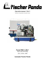
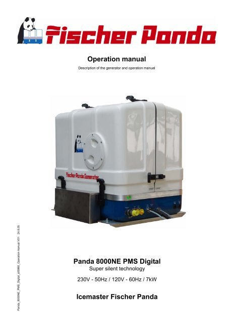
Operation manual<br />
Description of the generator and operation manual<br />
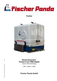
<strong>Panda</strong> <strong>8000NE</strong> <strong>PMS</strong> <strong>Digital</strong><br />
Super silent technology<br />
230V - 50Hz / 120V - 60Hz / 7kW<br />
Icemaster <strong>Fischer</strong> <strong>Panda</strong>
Current revison status<br />
Document<br />
Actual: <strong>Panda</strong>_<strong>8000NE</strong>_<strong>PMS</strong>_<strong>Digital</strong>_s00860_Operation manual.V01_24.8.05<br />
Replace:<br />
Revision Page<br />
ii
25 20 10 10 10<br />
since 1977<br />
Icemaster GmbH<br />
since 1978<br />
<strong>Fischer</strong> Marine<br />
<strong>Generators</strong><br />
since 1988<br />
Conclusion <strong>Fischer</strong> -<br />
Icemaster GmbH<br />
<strong>Fischer</strong> <strong>Panda</strong><br />
FISCHER GENERATORS have been manufactured since 1978 and are a well-known brand for first class diesel generators<br />
with especially effective sound-insulation.<br />
<strong>Fischer</strong> has been one of the leading manufacturers in respect of quality and know-how during this period.<br />
FISCHER, as the worldwide manufacturer of modern marine diesel generators, developed the Sailor-Silent series for<br />
example and produced a GFK sound-insulated capsule as early as 1979 and the basis for new generator technology.<br />
The companies <strong>Fischer</strong> and Icemaster amalgamated under the direction of Icemaster in 1988, in order to concentrate<br />
on the development of new products. Production was moved to Paderborn.<br />
The amalgamation of the two qualified companies led to the development of a complete new programme within a short<br />
space of time. The gensets developed at that time set new technological standards worldwide.<br />
The gensets became more efficient and powerful than other gensets in the same nominal performance range, because<br />
of the improved cooling. <strong>Panda</strong> generator demonstrated its superiority in several tests by renowned institutes and<br />
magazines during the past years. The patented VCS (voltage Control System) means it can meet all demands including<br />
motor speed. The start-booster (ASB) means <strong>Panda</strong> generators meet the highest demands in respect of voltage stability<br />
and starting values A <strong>Panda</strong> generator, with the same drive motor, produces 15% more effective output than the<br />
majority of conventional generators. This superiority in efficiency also ensures a fuel saving to the same extent.<br />
The 100% water-cooled <strong>Panda</strong> genset are currently manufactured in the performance range from 2 to 100 kW in<br />
various versions. Fast running motors are preferred for performances up to approx 30 kW (Nominal speed 3000 rpm).<br />
The heavier slow runners are preferred for the higher range. The fast running gensets have proved themselves many<br />
times for many uses, that they meet the demands in quality of yachts and vehicles, and offer space and weight saving<br />
of 50% compared to slow running generators.<br />
In addition to the <strong>Panda</strong> series, Icemaster also supply the super compact high-tech sound-insulated battery charging<br />
genset from the DC/AC <strong>Panda</strong> AGT series, which is a very interesting solution for the production of mobile power.<br />
The new HTG-alternators ensure that a charging rate of 285 amps is achieved that was scarcely thought possible for<br />
this compact construction. This alternator replaces a separate shipboard generators (constant 230 volts AC with up to<br />
3500 kW from the main machine)<br />
ICEMASTER GmbH, 33104 Paderborn, reserves all rights regarding text and graphics. Details are given to the best of our knowledge. No liability is accepted for correctness.<br />
Technical modifications for improving the product without previous notice may be undertaken without notice. Before installation, it must be ensured that the Pictures,<br />
diagrams and related material are applicable to the genset supplied. Enquiries must be made in case o doubt.<br />
iii<br />
since 1988<br />
100 % water cooled<br />
<strong>Panda</strong> generators<br />
since 1988<br />
<strong>Panda</strong> Vehicle<br />
<strong>Generators</strong>
Safety first<br />
These symbols are used throughout this manual and on labels on the maschine itself to warn of the possibility of personal<br />
injutry. Read these instructions carefully. It is essential that you read the instructions and safety regulations<br />
before you attempt to assemble or use unit.<br />
This danger symbol refers to toxic danger and draws attention to special warnings,<br />
instructions or procedures which, if not strictly observed, may result in severe personal<br />
injury or loss of life.<br />
This danger symbol refers to electric danger and draws attention to special<br />
warnings, instructions or procedures which, if not strictly observed, may result in<br />
electrical shock which will result in severe personal injury or loss of life.<br />
This danger symbol refers to electric danger and draws attention to special<br />
warnings, instructions or procedures which, if not strictly observed, may result in<br />
electrical shock which will result in severe personal injury or loss of life.<br />
This warning symbol draws attention to special warnings, instructions or procedures<br />
which, if not strictly observed, may result in damage or destruction of equipment,<br />
severe personal injury or loss of life.<br />
This warning symbol draws attention to special warnings, instructions or procedures<br />
which, if not strictly observed, may result in damage or destruction of equipment<br />
iv
Tools<br />
This symbols are used throughout this manual to show which tool must be used at maintenance or installation.<br />
X<br />
Spanners<br />
X = number of spanner<br />
Hook wrench for oil filter<br />
Screw driver, for slotted head screws and for recessed head screws<br />
Multimeter, multimeter with capacitor measuring<br />
Socket wrench set<br />
Hexagon wrench keys<br />
v
CALIFORNIA<br />
Proposition 65 Warning<br />
Diesel engine exhaust and some of its constituents<br />
are known to the State of California to cause cancer,<br />
birth defects, and other reproductive harm.<br />
Attention, Important Directions regarding Operation!<br />
1. The installation certificate must be completed when taken into use, and certified by a signature.<br />
2. The installation certificate must be despatched within two weeks of use to ICEMASTER.<br />
3. The official guaranty confirmation will be completed by ICEMASTER after receipt and sent to the customer.<br />
4. A guaranty must be shown to make any claims.<br />
Claims against the guaranty will not be accepted of the above said instructions are not, or only partially, carried out.<br />
Manufacturer declaration in terms of the machine guideline 98/37/EG .<br />
The generator is in such a way developed that all assembly groups correspond to the CE guidelines. If machine guideline<br />
98/37/EG is applicable, then it is forbidden to bring the generator into operation until it has been determined<br />
that the system into which the generator is to be installed in also corresponds to the regulations of the machine guideline<br />
98/37/EG. This concerns among other things the exhaust system, cooling system and the electrical installation.<br />
The evaluation of the "protection against contact" can only be accomplished in connection with the respective<br />
system. Likewise among other things responsibility for correct electrical connections, a safe ground wire connection,<br />
foreign body and humidity protection, protection against humidity due to excessive condensation as well as the overheating<br />
through appropriate and inappropriate use in its installed state on the respective machine lies within the<br />
responsibility of those who undertake installation of the generator in the system.<br />
Use the advantages of the customer registration:<br />
• Thus you receive to extended product informations, which are sometimes safety-relevant<br />
• you receive, if necessarily free Upgrades<br />
Far advantages:<br />
By your full information <strong>Fischer</strong> <strong>Panda</strong> technicians can give you fast assistance, since 90% of the disturbances result<br />
from errors in the periphery.<br />
Problems due to errors in the installation can be recognized in the apron.<br />
Technical Support by Internet: info@fischerpanda.com<br />
vi
Safety Precautions<br />
The electrical Installations may only be carried out be trained and<br />
tested personnel!<br />
The generator may not be taken into use with the cover removed.<br />
The rotating parts (belt-pulley, belts, etc) must be so covered and protected do that there is no danger to life and<br />
body!<br />
If a sound insulation covering must be produced at the place of installation, then well-placed signs must show that<br />
the generator can only be switched on with a closed capsule.<br />
All servicing-, maintenance or repair work may only carried out, when the motor is not running.<br />
Electrical voltages above 48 volts ( battery chargers greater than 36 volts) are always dangerous to life). The rules of<br />
the respective regional authority must be adhered to. Only an electrician may carry out installation of the electrical<br />
connections for safety reasons.<br />
Protective Conductor:<br />
The generator is „earthed " as standard (The centre and earth are connected by means of a bridge in the generator<br />
terminal box). This is a basic safety function, which offers basic safety as long as no other component has been<br />
installed. It is, above all, conceived for supply and an eventual test run.<br />
This "earth" (PEN) is only effective, if all parts of the electrical system is earthed, and has a common “potential”. The<br />
bridges can be removed, if this is required for technical reasons and another protection system has been installed.<br />
The full voltage is exploited at the AC control box, when the generator is run. It must therefore be ensured<br />
that the control box is closed and cannot be tampered with, if the generator is running.<br />
The battery must always be disconnected, if work on the generator or electrical system is to be carried out,<br />
so that the generator cannot be unintentionally started.<br />
Switch off all load when working on the generator<br />
All load must be disconnected, in order to avoid damages to the devices. In addition the semi conductors in the AC<br />
control box must be disconnected in order to avoid the boat capacitors being activated. The minus pole of the battery<br />
ought to be removed.<br />
Capacitors are required to run the generator. These have two varying functions:<br />
A) The working capacitors<br />
B) The (Booster) capacitors<br />
Both Groups are located in a sound cover of the genset.<br />
Capacitors are electrical stores. There could be a residual of high electrical current at the contacts for a period disconnection<br />
from the circuit. The contacts my not be touched for safety reasons, If the capacitors are to be exchanged<br />
or checked, then a short circuit between the contacts should be made so that the stored energy is discharged.<br />
If the generator is switched off in the normal manner, the working capacitors are automatically discharged by means<br />
of the windings. The booster capacitors are discharged by means of internal discharge resistors.<br />
All capacitors must be short-circuited before work is carried out on the AC-Control box for safety reasons.<br />
vii
viii
Table of Contents<br />
Current revison status ........................................................................................................... ii<br />
Safety first.............................................................................................................................. iv<br />
Tools........................................................................................................................................ v<br />
Safety Precautions ............................................................................................................... vii<br />
A The <strong>Panda</strong> Generator .................................................................................................... 3<br />
A.1 Description of the Generator ........................................................................................... 3<br />
A.1.1 Right Side View - <strong>Panda</strong> 8000 NE 50Hz ............................................................................. 3<br />
A.1.2 Left Side View - <strong>Panda</strong> 8000 NE 50Hz ............................................................................... 4<br />
A.1.3 Front View - <strong>Panda</strong> 8000 NE 50Hz ..................................................................................... 5<br />
A.1.4 Back View - <strong>Panda</strong> 8000 NE 50Hz...................................................................................... 6<br />
A.1.5 View from Above - <strong>Panda</strong> 8000 NE 50Hz ........................................................................... 7<br />
A.1.6 Right Side View - <strong>Panda</strong> 8000 NE 60Hz ............................................................................. 8<br />
A.1.7 Left Side View - <strong>Panda</strong> 8000 NE 60Hz ............................................................................... 9<br />
A.1.8 Front View - <strong>Panda</strong> 8000 NE 60Hz ................................................................................... 10<br />
A.1.9 Back View - <strong>Panda</strong> 8000 NE 60Hz.................................................................................... 11<br />
A.1.10 View from Above - <strong>Panda</strong> 8000 NE 60Hz ......................................................................... 12<br />
A.2 Details of functional units ............................................................................................. 13<br />
A.2.1 Remote control panel ........................................................................................................ 13<br />
A.2.2 Components of Cooling System (Raw water ) .................................................................. 14<br />
A.2.3 Components of Cooling System (Freshwater) .................................................................. 16<br />
A.2.4 Components of the fuel system......................................................................................... 20<br />
A.2.5 Components of combustion air.......................................................................................... 22<br />
A.2.6 Components of the electrical system ................................................................................ 25<br />
A.2.7 Sensors and switches for operating surveillance .............................................................. 34<br />
A.2.8 Components of the oil circuit ............................................................................................. 38<br />
A.3 Operation instructions ................................................................................................... 39<br />
A.3.1 Preliminary remark ............................................................................................................ 39<br />
A.3.2 Daily routine checks before starting .................................................................................. 40<br />
A.3.3 Starting Generator............................................................................................................. 41<br />
A.3.4 Stopping the Generator ..................................................................................................... 41<br />
B Remote control panel ................................................................................................. 43<br />
24.8.05 <strong>Panda</strong>_<strong>8000NE</strong>_<strong>PMS</strong>_<strong>Digital</strong>_s00860_Operation manual.V01 - Table of contents - Page 1
Intentionally Blank<br />
Page 2 <strong>Panda</strong>_<strong>8000NE</strong>_<strong>PMS</strong>_<strong>Digital</strong>_s00860_Operation manual.V01 - Table of contents 24.8.05
The <strong>Panda</strong> Generator<br />
A. The <strong>Panda</strong> Generator<br />
A.1 Description of the Generator<br />
A.1.1 Right Side View - <strong>Panda</strong> 8000 NE 50Hz<br />
01<br />
02<br />
03<br />
04<br />
05<br />
06<br />
07<br />
08<br />
09<br />
01. Thermostat housing<br />
02. 12V DC-alternator<br />
03. V-belt for DC-alternator and cooling water pump<br />
04. Engine oil filter<br />
05. Oil pressure switch<br />
06. Sound cover - base part<br />
07. Power terminal box with measuring board<br />
08. Starter motor<br />
09. Solenoid switch for starter motor<br />
10. Water-cooled exhaust elbow<br />
11. Freshwater return pipe<br />
12. Thermo-sensor frehwater out<br />
13. Thermo-sensor exhaust<br />
10<br />
13 15 16<br />
24.8.05 <strong>Panda</strong>_<strong>8000NE</strong>_<strong>PMS</strong>_<strong>Digital</strong>_s00860_Operation manual.V01 - Chapter A: The <strong>Panda</strong> Generator Page 3<br />
11<br />
12<br />
14<br />
25<br />
24<br />
23<br />
22<br />
19<br />
17<br />
21<br />
20<br />
14. Exhaust connection<br />
15. Exhaust output<br />
16. Connection expernal ventilation valve<br />
17. Intake to external cooling water expansion tank<br />
18. Backflow from external cooling water expansion tank<br />
19. Thermo-sensor raw water out<br />
20. Generator housing with coil<br />
21. Injector for raw water<br />
22. Solid state relay for booster capacitor<br />
23. Booster capacitor (1x60µF)<br />
24. Excitation capacitors (4x50µF)<br />
25. Cooling water filler neck<br />
18
A.1.2 Left Side View - <strong>Panda</strong> 8000 NE 50Hz<br />
24<br />
23<br />
01<br />
13<br />
02<br />
03<br />
01. Excitation capacitors (4x50µF)<br />
02. Charge control for DC-alternator<br />
03. Air suction housing with air filter<br />
04. Failure bypass switch<br />
05. Air suction hose to induction elbow<br />
06. Fuel solenoid valve<br />
07. Stop solenoid<br />
08. Ventilation screw thermostat housing<br />
09. Ventilation screw internal cooling water pump<br />
10. Pulley for internal cooling water pump<br />
11. Actuator for speed control<br />
12. Oil dipstick<br />
13. Cooling water connection block<br />
04 05 06 07<br />
The <strong>Panda</strong> Generator<br />
22 21 20 19 18<br />
17<br />
Page 4 <strong>Panda</strong>_<strong>8000NE</strong>_<strong>PMS</strong>_<strong>Digital</strong>_s00860_Operation manual.V01 - Chapter A: The <strong>Panda</strong> Generator 24.8.05<br />
11<br />
12<br />
08<br />
14. Raw water pump<br />
15. Raw water intake hose<br />
16. Fuel filter<br />
17. Raw water inlet<br />
18. Thermo-sensor freshwater in<br />
19. Power relays<br />
20. Electical fuses<br />
21. Cooling water pipe, connection block - cooling water<br />
pump<br />
22. Control box<br />
23. Fuse for DC-system (30A)<br />
24. Sound cover - base part<br />
09<br />
10<br />
14<br />
15<br />
16
The <strong>Panda</strong> Generator<br />
A.1.3 Front View - <strong>Panda</strong> 8000 NE 50Hz<br />
09<br />
13<br />
02<br />
07<br />
14 15 16 17 18 19 20<br />
21 22<br />
01. Ventilation screw thermostat housing<br />
02. Ventilation screw internal cooling water pump<br />
03. Thermostat housing with thermostat set<br />
04. Pulley for internal cooling water pump<br />
05. 12V DC-alternator<br />
06. V-belt for DC-alternator and internal cooling water pump<br />
07. Raw water pump<br />
08. Freshwater intake pipe<br />
09. Hose for raw water intake<br />
10. Engine oil filter<br />
11. Oil pressure switch<br />
04<br />
12<br />
24.8.05 <strong>Panda</strong>_<strong>8000NE</strong>_<strong>PMS</strong>_<strong>Digital</strong>_s00860_Operation manual.V01 - Chapter A: The <strong>Panda</strong> Generator Page 5<br />
08<br />
03<br />
05<br />
10<br />
01<br />
06<br />
11<br />
12. Injection hose, freshwater from external expansion tank<br />
13. Fuel filter<br />
14. Control box<br />
15. Raw water inlet<br />
16. Fuel intake connection<br />
17. Fuel backflow connection<br />
18. Cable fuel pump<br />
19. Oil drain hose<br />
20. Cable for fuel level sensor<br />
21. Passage for cable starter battery minus (-)<br />
22. Passage for cable starter battery plus (+)
A.1.4 Back View - <strong>Panda</strong> 8000 NE 50Hz<br />
01<br />
03<br />
06<br />
02<br />
07<br />
09<br />
12 13 14<br />
15<br />
01. Cooling water filler neck<br />
02. Booster capacitor (1x60µF)<br />
03. Water-cooled exhaust elbow<br />
04. Air suction housing with air filter<br />
05. Excitation capacitors (4x50µF)<br />
06. Solid state relay for booster capacitor<br />
07. Generator front cover<br />
08. Fuse for DC-system (30A)<br />
04<br />
The <strong>Panda</strong> Generator<br />
Page 6 <strong>Panda</strong>_<strong>8000NE</strong>_<strong>PMS</strong>_<strong>Digital</strong>_s00860_Operation manual.V01 - Chapter A: The <strong>Panda</strong> Generator 24.8.05<br />
05<br />
08<br />
09. Cover for oil-cooled bearing<br />
10. Control box<br />
11. Passage for cable control panel<br />
12. Connection external ventilation valve<br />
13. Intake to external cooling water expansion tank<br />
14. Backflow from external cooling water expansion tank<br />
15. Passage for cable load<br />
10<br />
11
The <strong>Panda</strong> Generator<br />
A.1.5 View from Above - <strong>Panda</strong> 8000 NE 50Hz<br />
01 03 04 05 06<br />
07 08<br />
09<br />
02<br />
10<br />
01. Solid state relay for booster capacitor<br />
02. Booster capacitor (1x60µF)<br />
03. Cooling water filler neck<br />
04. Ventilation hose to external expansion tank<br />
05. Water-cooled exhaust elbow<br />
06. Engine oil filler neck<br />
07. 12V DC-alternator<br />
08. Ventilation screw thermostat housing<br />
09. Excitation capacitors (4x50µF)<br />
10. Charge control for DC-alternator<br />
11 12 13 14 15 16 17 18 19<br />
11. Air suction housing with air filter<br />
12. Control box<br />
13. Cylinder head thermo-switch<br />
14. Air suction hose to induction elbow<br />
15. Actuator<br />
16. Fuel solenoid valve<br />
17. Stop solenoid<br />
18. Ventilation screw internal cooling water pump<br />
19. Pulley for internal cooling water pump<br />
24.8.05 <strong>Panda</strong>_<strong>8000NE</strong>_<strong>PMS</strong>_<strong>Digital</strong>_s00860_Operation manual.V01 - Chapter A: The <strong>Panda</strong> Generator Page 7
A.1.6 Right Side View - <strong>Panda</strong> 8000 NE 60Hz<br />
01<br />
02<br />
03<br />
04<br />
05<br />
06<br />
07<br />
08<br />
09<br />
01. Thermostat housing<br />
02. 12V DC-alternator<br />
03. V-belt for DC-alternator and cooling water pump<br />
04. Engine oil filter<br />
05. Oil pressure switch<br />
06. Sound cover - base part<br />
07. Power terminal box with measuring board<br />
08. Starter motor<br />
09. Solenoid switch for starter motor<br />
10. Water-cooled exhaust elbow<br />
11. Freshwater return pipe<br />
12. Thermo-sensor frehwater out<br />
10<br />
13 15 16<br />
The <strong>Panda</strong> Generator<br />
Page 8 <strong>Panda</strong>_<strong>8000NE</strong>_<strong>PMS</strong>_<strong>Digital</strong>_s00860_Operation manual.V01 - Chapter A: The <strong>Panda</strong> Generator 24.8.05<br />
11<br />
12<br />
14<br />
24<br />
23<br />
22<br />
19<br />
17<br />
21<br />
20<br />
13. Thermo-sensor exhaust<br />
14. Exhaust connection<br />
15. Exhaust output<br />
16. Connection expernal ventilation valve<br />
17. Intake to external cooling water expansion tank<br />
18. Backflow from external cooling water expansion tank<br />
19. Thermo-sensor raw water out<br />
20. Generator housing with coil<br />
21. Injector for raw water<br />
22. Solid state relays for booster capacitors<br />
23. Booster capacitors (2x40µF)<br />
24. Cooling water filler neck<br />
18
The <strong>Panda</strong> Generator<br />
A.1.7 Left Side View - <strong>Panda</strong> 8000 NE 60Hz<br />
24<br />
23<br />
01<br />
13<br />
02<br />
03<br />
01. Excitation capacitors (4x50µF)<br />
02. Charge control for DC-alternator<br />
03. Air suction housing with air filter<br />
04. Failure bypass switch<br />
05. Air suction hose to induction elbow<br />
06. Fuel solenoid valve<br />
07. Stop solenoid<br />
08. Ventilation screw thermostat housing<br />
09. Ventilation screw internal cooling water pump<br />
10. Pulley for internal cooling water pump<br />
11. Actuator for speed control<br />
12. Oil dipstick<br />
13. Cooling water connection block<br />
04 05 06 07<br />
22 21 20 19 18<br />
17<br />
24.8.05 <strong>Panda</strong>_<strong>8000NE</strong>_<strong>PMS</strong>_<strong>Digital</strong>_s00860_Operation manual.V01 - Chapter A: The <strong>Panda</strong> Generator Page 9<br />
11<br />
12<br />
08<br />
14. Raw water pump<br />
15. Raw water intake hose<br />
16. Fuel filter<br />
17. Raw water inlet<br />
18. Thermo-sensor freshwater in<br />
19. Power relays<br />
20. Electical fuses<br />
21. Cooling water pipe, connection block - cooling water<br />
pump<br />
22. Control box<br />
23. Fuse for DC-system (30A)<br />
24. Sound cover - base part<br />
09<br />
10<br />
14<br />
15<br />
16
A.1.8 Front View - <strong>Panda</strong> 8000 NE 60Hz<br />
09<br />
13<br />
02<br />
07<br />
14 15 16 17 18 19 20<br />
21 22<br />
01. Ventilation screw thermostat housing<br />
02. Ventilation screw internal cooling water pump<br />
03. Thermostat housing with thermostat set<br />
04. Pulley for internal cooling water pump<br />
05. 12V DC-alternator<br />
06. V-belt for DC-alternator and internal cooling water pump<br />
07. Raw water pump<br />
08. Freshwater intake pipe<br />
09. Hose for raw water intake<br />
10. Engine oil filter<br />
11. Oil pressure switch<br />
04<br />
12<br />
The <strong>Panda</strong> Generator<br />
Page 10 <strong>Panda</strong>_<strong>8000NE</strong>_<strong>PMS</strong>_<strong>Digital</strong>_s00860_Operation manual.V01 - Chapter A: The <strong>Panda</strong> Generator 24.8.05<br />
08<br />
03<br />
05<br />
10<br />
01<br />
06<br />
11<br />
12. Injection hose, freshwater from external expansion tank<br />
13. Fuel filter<br />
14. Control box<br />
15. Raw water inlet<br />
16. Fuel intake connection<br />
17. Fuel backflow connection<br />
18. Cable fuel pump<br />
19. Oil drain hose<br />
20. Cable for fuel level sensor<br />
21. Passage for cable starter battery minus (-)<br />
22. Passage for cable starter battery plus (+)
The <strong>Panda</strong> Generator<br />
A.1.9 Back View - <strong>Panda</strong> 8000 NE 60Hz<br />
01<br />
03<br />
06<br />
02<br />
07<br />
09<br />
12 13 14<br />
15<br />
01. Cooling water filler neck<br />
02. Booster capacitors (2x40µF)<br />
03. Water-cooled exhaust elbow<br />
04. Air suction housing with air filter<br />
05. Excitation capacitors (4x50µF)<br />
06. Solid state relays for booster capacitors<br />
07. Generator front cover<br />
08. Fuse for DC-sysetm (30A)<br />
04<br />
24.8.05 <strong>Panda</strong>_<strong>8000NE</strong>_<strong>PMS</strong>_<strong>Digital</strong>_s00860_Operation manual.V01 - Chapter A: The <strong>Panda</strong> Generator Page 11<br />
05<br />
08<br />
09. Cover for oil-cooled bearing<br />
10. Control box<br />
11. Passage for cable control panel<br />
12. Connection external ventilation valve<br />
13. Intake to external cooling water expansion tank<br />
14. Backflow from external cooling water expansion tank<br />
15. Passage for cable load<br />
10<br />
11
A.1.10View from Above - <strong>Panda</strong> 8000 NE 60Hz<br />
01 03 04 05 06<br />
07 08<br />
02<br />
09<br />
10<br />
01. Solid state relays for booster capacitors<br />
02. Booster capacitors (2x40µF)<br />
03. Cooling water filler neck<br />
04. Ventilation hose to external expansion tank<br />
05. Water-cooled exhaust elbow<br />
06. Engine oil filler neck<br />
07. 12V DC-alternator<br />
08. Ventilation screw thermostat housing<br />
09. Excitation capacitors (4x50µF)<br />
10. Charge control for DC-alternator<br />
The <strong>Panda</strong> Generator<br />
11 12 13 14 15 16 17 18 19<br />
11. Air suction housing with air filter<br />
12. Control box<br />
13. Cylinder head thermo-switch<br />
14. Air suction hose to induction elbow<br />
15. Actuator<br />
16. Fuel solenoid valve<br />
17. Stop solenoid<br />
18. Ventilation screw internal cooling water pump<br />
19. Pulley for internal cooling water pump<br />
Page 12 <strong>Panda</strong>_<strong>8000NE</strong>_<strong>PMS</strong>_<strong>Digital</strong>_s00860_Operation manual.V01 - Chapter A: The <strong>Panda</strong> Generator 24.8.05
The <strong>Panda</strong> Generator<br />
A.2 Details of functional units<br />
A.2.1 Remote control panel<br />
The remote control panel is equipped with some new monitoring functions, which increases the<br />
operational safety of the generator. A failure message is shown over contacts which are normaly<br />
closed. If a connection is intermitted triggers this a failure message.<br />
02<br />
01. <strong>Digital</strong> display<br />
02. S1 Button „ON/OFF“ „Stand by“<br />
03. S2 Button „Alarm mute / Program level“<br />
Fig. A.1: Remote control panel<br />
24.8.05 <strong>Panda</strong>_<strong>8000NE</strong>_<strong>PMS</strong>_<strong>Digital</strong>_s00860_Operation manual.V01 - Chapter A: The <strong>Panda</strong> Generator Page 13<br />
01<br />
03 04 05 06<br />
04. S3 Button „Screen shift“<br />
05. S4 Button „rpm Shift n1/n2“<br />
06. S5 Button „Generator run/stop / Select Save“
A.2.2 Components of Cooling System (Raw water )<br />
Fig. A.2: Raw water intake<br />
Fig. A.3: Raw water impeller pump<br />
Fig. A.4: Heat exchanger<br />
Raw water intake<br />
The diagram shows the supply pipes for<br />
the generator. The connection neck for<br />
the raw water connection is shown on the<br />
left hand side. The cross-section of the<br />
intake pipe should be nominally larger<br />
than the generator connection.<br />
Raw water impeller pump<br />
The raw water pump is fitted with a rubber<br />
impeller. This pump is self-inductive.<br />
If, for example, you forget to open the sea<br />
valve, then you must expect the impeller<br />
to be destroyed after a short period of<br />
time. It is recommended to store several<br />
impellers on board as spare parts.<br />
Heat exchanger<br />
Separates the raw water system from the<br />
freshwater system.<br />
The <strong>Panda</strong> Generator<br />
Page 14 <strong>Panda</strong>_<strong>8000NE</strong>_<strong>PMS</strong>_<strong>Digital</strong>_s00860_Operation manual.V01 - Chapter A: The <strong>Panda</strong> Generator 24.8.05
The <strong>Panda</strong> Generator<br />
Ventilation valve<br />
A siphon must be installed if the generator<br />
sinks below the water line because of the<br />
rocking of the boat, even if it is only for a<br />
short period of time. A hosepipe on the<br />
generator casing has been produced for<br />
this. Both connecting pieces are bridged<br />
by a formed piece of hose.<br />
Raw water injector nozzle<br />
The injection point for the marine generator<br />
water-cooled exhaust system is situated<br />
at the exhaust connection pieces The<br />
exhaust connections must be regularly<br />
checked for signs of corrosion.<br />
Fig. A.5: Connection external vent valve<br />
Fig. A.6: Raw water injector nozzle<br />
24.8.05 <strong>Panda</strong>_<strong>8000NE</strong>_<strong>PMS</strong>_<strong>Digital</strong>_s00860_Operation manual.V01 - Chapter A: The <strong>Panda</strong> Generator Page 15
A.2.3 Components of Cooling System (Freshwater)<br />
Fig. A.7: Cooling water filler neck<br />
Fig. A.8: Freshwater backflow<br />
Fig. A.9: Ventilation pipe<br />
Cooling water filler neck<br />
The cooling water filler neck is situated at<br />
the water-cooled manifold and only used,<br />
when the generator is initially started.<br />
Since the generator is normally already<br />
filled with cooling water, these components<br />
are only by the user, if repairs are to<br />
be carried out. Topping up with cooling<br />
water may only carried out at the external<br />
cooling water compensation tank. Note<br />
that the water level in the cooling water<br />
compensation tank is only 20% of the volume<br />
in a cold state.<br />
Freshwater backflow<br />
The cooling water is fed to the heat<br />
exchanger from the water-cooled manifold<br />
by means of the pipe shown in the diagram.<br />
Ventilation pipe<br />
The ventilation pipe at the water-cooled<br />
exhaust manifold leads to the external<br />
expansion tank. This pipe only serves as<br />
a ventilation pipe, if both pipes are to be<br />
connected to the external expansion tank<br />
(ventilation pipe and intake pipe).<br />
The <strong>Panda</strong> Generator<br />
Page 16 <strong>Panda</strong>_<strong>8000NE</strong>_<strong>PMS</strong>_<strong>Digital</strong>_s00860_Operation manual.V01 - Chapter A: The <strong>Panda</strong> Generator 24.8.05
The <strong>Panda</strong> Generator<br />
Hose connection pieces for the external<br />
expansion tank<br />
The external expansion tank is connected<br />
by two hose connections. The connecting<br />
pieces shown here serves as constant<br />
ventilation for the water-cooling system.<br />
In case the external expansion tank is<br />
connected with two hoses, the system will<br />
ventilate itself. In this case, additional ventilation<br />
is only necessary when the generator<br />
is initially filled, or if the cooling water<br />
is not circulating.<br />
Heat exchanger<br />
Separates the raw water system from the<br />
freshwater system.<br />
Cooling water connection block<br />
The cooling water is fed to the generator<br />
and drained via the cooling water connection<br />
block. The cooling water connection<br />
block consists of an aluminium alloy,<br />
which can behave like a sacrificial anode.<br />
Fig. A.10: External expansion tank<br />
Fig. A.11: Heat exchanger<br />
Fig. A.12: Cooling water connection block<br />
24.8.05 <strong>Panda</strong>_<strong>8000NE</strong>_<strong>PMS</strong>_<strong>Digital</strong>_s00860_Operation manual.V01 - Chapter A: The <strong>Panda</strong> Generator Page 17
B<br />
Fig. A.13: Cooling water pipe<br />
Fig. A.14: Internal cooling water pump<br />
A<br />
Fig. A.15: Internal cooling water pump<br />
Cooling water pipe<br />
From the cooling water connection block<br />
the fresh water is lead to the water pump<br />
Internal cooling water pump<br />
The diesel motor cooling water pump (see<br />
arrow) aids the circulation of the internal<br />
freshwater system.<br />
Cooling water intake<br />
A.) To the thermostat housing<br />
B.) From the external expansion tank<br />
The intake pipe from the external cooling<br />
water expansion tank is connected to the<br />
point shown with „B“.<br />
The <strong>Panda</strong> Generator<br />
Page 18 <strong>Panda</strong>_<strong>8000NE</strong>_<strong>PMS</strong>_<strong>Digital</strong>_s00860_Operation manual.V01 - Chapter A: The <strong>Panda</strong> Generator 24.8.05
The <strong>Panda</strong> Generator<br />
Ventilation screw cooling water pump<br />
The ventilation screw above the cooling<br />
water pump casing may not be opened,<br />
whilst the generator is running. If this<br />
occurs by mistake, air will be drawn<br />
through the opening. Extensive ventilation<br />
of the whole system is then necessary.<br />
Ventilation screw thermostat housing<br />
The ventilation screw on the thermostat<br />
housing should occasionally be opened<br />
for control purposes. Standing machinery<br />
should principally carry out ventilating.<br />
Water-cooled exhaust manifold<br />
The manifold is cooled by means of the<br />
internal cooling system (freshwater). The<br />
cooling water filler necks on the casing of<br />
the manifold may not be opened. These<br />
cooling water necks are only required to<br />
fill the motor with cooling water in cases of<br />
repair. The normal cooling water controls<br />
may only be carried out at the external<br />
expansion tank.<br />
Fig. A.16: Ventilation screw cooling water pump<br />
Fig. A.17: Ventilation screw thermostat housin<br />
Fig. A.18: Water-cooled exhaust manifold<br />
24.8.05 <strong>Panda</strong>_<strong>8000NE</strong>_<strong>PMS</strong>_<strong>Digital</strong>_s00860_Operation manual.V01 - Chapter A: The <strong>Panda</strong> Generator Page 19
A.2.4 Components of the fuel system<br />
1 2<br />
Fig. A.19: External fuel pump<br />
Fig. A.20: Fuel connections<br />
Fig. A.21: Fuel filter<br />
External fuel pump<br />
The <strong>Panda</strong> generator is always supplied<br />
with an external, electrical (12 V of DC) fuel<br />
pump. The fuel pump must be always<br />
installed in the proximity of the tank. The<br />
electrical connections with the lead planned<br />
for it are before-installed at the generator.<br />
Since the suction height and the<br />
supply pressure are limited, it can be<br />
sometimes possible that for reinforcement<br />
a second pump must be installed.<br />
Connecting pieces for the fuel pipe<br />
1. Fuel intake<br />
2. Fuel backflow<br />
Fuel filter<br />
A consequential filtering of fuel is especially<br />
important for all marine systems. A fine<br />
filter, which is firmly attached to the inside<br />
of the sound insulation capsule for the<br />
marine version, is supplied on delivery, and<br />
loose for other makes. In all cases a further<br />
pre-filter with water separator must be<br />
installed. See directions for fuel filter installation.<br />
The <strong>Panda</strong> Generator<br />
Page 20 <strong>Panda</strong>_<strong>8000NE</strong>_<strong>PMS</strong>_<strong>Digital</strong>_s00860_Operation manual.V01 - Chapter A: The <strong>Panda</strong> Generator 24.8.05
The <strong>Panda</strong> Generator<br />
Fuel solenoid valve<br />
The fuel solenoid valve opens automatically<br />
if „START“ is pressed on the remote<br />
control panel“. The solenoid closes, if the<br />
generator is switched to „OFF“ position. It<br />
takes a few seconds before the generator<br />
stops. If the generator does not start or<br />
does not run smoothly (i.e. stutters), or<br />
does not attain full speed, then the cause<br />
is fore-mostly the solenoid.<br />
1) Fuel solenoid valve<br />
2) Ventilation screw solenoid valve<br />
3) Magnetic coil<br />
Injection nozzles<br />
If the engine does not start after the ventilation,<br />
the fuel injection lines must be deaerated<br />
individually.<br />
Glow plugs<br />
The glow plugs serve the pre-chamber for<br />
the heating with cold start. The heat-treat<br />
fixture must be operated, if the temperature<br />
of the generator is under 16°C. This<br />
is practically with each start the case. The<br />
heat-treat fixture may be held down also<br />
during start and favoured the starting procedure.<br />
Fig. A.22: Fuel solenoid valve<br />
Fig. A.23: Injection nozzles<br />
Fig. A.24: Glow plugs<br />
24.8.05 <strong>Panda</strong>_<strong>8000NE</strong>_<strong>PMS</strong>_<strong>Digital</strong>_s00860_Operation manual.V01 - Chapter A: The <strong>Panda</strong> Generator Page 21<br />
3<br />
2<br />
1
A.2.5 Components of combustion air<br />
Fig. A.25: Stop solenoid<br />
Fig. A.26: Combustion air intake<br />
Fig. A.27: Sound cover drillings<br />
Stop solenoid for engine stop<br />
Some model are additional equipped with<br />
an stop solenoid. The generator is stopped<br />
by the co-operation of the stop solenoid<br />
immediately after switching off. The<br />
adjustment of the stop solenoid must<br />
always be checked, in order to be sure<br />
that the stop lever can move also during<br />
the operation freely and is not under prestressing.<br />
Air suction openings at the sound<br />
cover<br />
The sound cover for the marine generator<br />
is normally provided at the lower surface<br />
with drillings, through which the combustion<br />
air can influx.<br />
It must be consistently paid attention that<br />
the generator is installed in such a way<br />
that from down no water can arrive into<br />
the proximity of these air openings. (minimum<br />
distance 150 mm)<br />
Drillings for combustion air at the<br />
sound cover<br />
Drillings at the lower surface of the sound<br />
cover serve the admission of fresh air for<br />
the entrance. It must be safe that no raw<br />
water or other water can come into this<br />
range of this openings. If air is sucked in<br />
through these openings, water can penetrate<br />
also into the sound cover.<br />
The <strong>Panda</strong> Generator<br />
Page 22 <strong>Panda</strong>_<strong>8000NE</strong>_<strong>PMS</strong>_<strong>Digital</strong>_s00860_Operation manual.V01 - Chapter A: The <strong>Panda</strong> Generator 24.8.05
The <strong>Panda</strong> Generator<br />
Air suction housing with 12V DC<br />
charge control<br />
The shown air suction housing shows the<br />
12V DC charge control (pos. 2) at the<br />
exterior. This charge control is to be chekked,<br />
if the 12V DC voltage is not correct.<br />
If the cover (pos. 1) is removed, the inside<br />
of the air suction housing becomes visible.<br />
In these air suction housings is a filter element.<br />
At the marine version the filter is<br />
normally not changed. It should be chekked<br />
once in a while.<br />
Air suction housing with air filter set<br />
The figure shows the air filter element in<br />
the air suction housing. However the<br />
return pipe of the crank case exhaust<br />
flows also into the air suction housing, it<br />
can be faced with older generators and/or<br />
with engines on high running time that oel<br />
vapors affect the air filter. Therefore an<br />
check is advisable once in a while.<br />
Combustion chamber intake elbow<br />
The figure shows the induction elbow at<br />
the combustion engine. At the front of this<br />
induction elbow you can see the hose<br />
connection between air suction housings<br />
and induction elbow. The air filter must be<br />
checked, if this hose pulls together at operation.<br />
Fig. A.28: Air suction housing<br />
Fig. A.29: Air filter set<br />
Fig. A.30: Combustion chamber intake elbow<br />
24.8.05 <strong>Panda</strong>_<strong>8000NE</strong>_<strong>PMS</strong>_<strong>Digital</strong>_s00860_Operation manual.V01 - Chapter A: The <strong>Panda</strong> Generator Page 23<br />
2<br />
1
Fig. A.31: Exhaust elbow<br />
Fig. A.32: Exhaust connection<br />
Fig. A.33: Exhaust outlet<br />
Exhaust elbow<br />
On the back of the engine is the watercooled<br />
exhaust elbow. On the top side the<br />
pipe union for the internal raw water circuit<br />
is to be seen and the filler neck for the<br />
cooling water. This cooling water filler<br />
neck is used only at first filling. Control of<br />
the cooling water and if necessary refill<br />
takes place at the external cooling water<br />
expansion tank.<br />
Exhaust connection at the exhaust<br />
elbow<br />
Raw water from the external cooling circle<br />
is fed here.<br />
Exhaust outlet<br />
Connect the exhaust pipe with the water<br />
lock.<br />
The <strong>Panda</strong> Generator<br />
Page 24 <strong>Panda</strong>_<strong>8000NE</strong>_<strong>PMS</strong>_<strong>Digital</strong>_s00860_Operation manual.V01 - Chapter A: The <strong>Panda</strong> Generator 24.8.05
The <strong>Panda</strong> Generator<br />
A.2.6 Components of the electrical system<br />
Passage for cable starter battery<br />
1. Passage for cable starter battery (plus)<br />
2. Passage for cable starter battery<br />
(minus)<br />
During the connection to the starter battery<br />
it must be always ensured that the<br />
contact is perfectly guaranteed.<br />
Connection starter battery plus cable<br />
The plus cable of the starter battery must<br />
be connected at the solenoid of the stater<br />
motor.<br />
Connection starter battery minus cable<br />
The minus cable of the starter battery<br />
must be connected at the right engine<br />
bracket when you look fron the front side.<br />
Fig. A.34: Passage for able starter battery<br />
Fig. A.35: Connection starter battery plus cable<br />
Fig. A.36: Connection starter battery minus cable<br />
24.8.05 <strong>Panda</strong>_<strong>8000NE</strong>_<strong>PMS</strong>_<strong>Digital</strong>_s00860_Operation manual.V01 - Chapter A: The <strong>Panda</strong> Generator Page 25<br />
2<br />
1
2<br />
1<br />
Fig. A.37: Passage for load and remote control panel<br />
Fig. A.38: Terminal block 120V/60Hz<br />
Fig. A.39: Terminal block 230V/50Hz<br />
Passage for load and remote control<br />
panel<br />
Terminal block for load 120V/60Hz<br />
Terminal block for load 230V/50Hz<br />
The <strong>Panda</strong> Generator<br />
Page 26 <strong>Panda</strong>_<strong>8000NE</strong>_<strong>PMS</strong>_<strong>Digital</strong>_s00860_Operation manual.V01 - Chapter A: The <strong>Panda</strong> Generator 24.8.05
The <strong>Panda</strong> Generator<br />
Panel interface (on VCS)<br />
Connection external fuel pump and<br />
fuel level sensor<br />
At the front of the sound cover is the withdrawal<br />
for the cable for the fuel pump and<br />
the fuel level sensor.<br />
1. Cable for fuel pump<br />
2. Cable for fuel level sensor<br />
Starter motor<br />
1. Starter motor and<br />
2. Solenoid switch<br />
The Diesel engine is electrically started.<br />
On the back of the engine is accordingly<br />
the electrical starter with the solenoid<br />
switch.<br />
Fig. A.40: Panel interface (on VCS)<br />
Fig. A.41: Fuel pump and fuel level sensor cable<br />
Fig. A.42: Starter motor<br />
1 2<br />
24.8.05 <strong>Panda</strong>_<strong>8000NE</strong>_<strong>PMS</strong>_<strong>Digital</strong>_s00860_Operation manual.V01 - Chapter A: The <strong>Panda</strong> Generator Page 27<br />
2<br />
1
Fig. A.43: Actuator<br />
Fig. A.44: DC-alternator<br />
Fig. A.45: Charge control<br />
Actuator for speed regulation<br />
The generator voltage is determined by<br />
progressive speed control through "VCS"<br />
in conjunction with the speed actuator.<br />
Speed increases with increasing load.<br />
DC-alternator<br />
All <strong>Panda</strong> generators from <strong>Panda</strong> 6.000<br />
are provided with its own charge system<br />
for the 12V DC mains. This DC-alternator<br />
is powered over a v-belt together with the<br />
internal cooling water pump.<br />
The 12V charge system may be used only<br />
for the generator-own starter battery.<br />
Charge control for DC-alternator<br />
The voltage regulator for the 12V DCalternator<br />
is on the back of the air suction<br />
housing. The housing is formed for cooling<br />
purposes. The voltage regulator may<br />
not be covered from the outside. The surface<br />
must be accessible for the cooling.<br />
The <strong>Panda</strong> Generator<br />
Page 28 <strong>Panda</strong>_<strong>8000NE</strong>_<strong>PMS</strong>_<strong>Digital</strong>_s00860_Operation manual.V01 - Chapter A: The <strong>Panda</strong> Generator 24.8.05
The <strong>Panda</strong> Generator<br />
Generator power terminal box 120V/<br />
60Hz<br />
At the back of the generator is the generator<br />
power terminal box. In this box the<br />
electrical connection points of the AC<br />
generator are connected. Here is also the<br />
bridge for the protective grounding of the<br />
generator. The cover may only be removed,<br />
if it is guaranteed that the generator<br />
cannot be inadvertently started.<br />
Generator power terminal box 230V/<br />
50Hz<br />
At the back of the generator is the generator<br />
power terminal box. In this box the<br />
electrical connection points of the AC<br />
generator are connected. Here is also the<br />
bridge for the protective grounding of the<br />
generator. The cover may only be removed,<br />
if it is guaranteed that the generator<br />
cannot be inadvertently started.<br />
Relays<br />
K0 power relay for ground isolate relay<br />
K1 power relay for starter motor<br />
K2 power relay for glow plugs<br />
K2.1 power relay for glow plugs<br />
K3 power relay for fuel pump<br />
K4 power relay for stop solenoid<br />
Fig. A.46: Generator power terminal box 120V/60Hz<br />
Fig. A.47: Generator power terminal box 230V/50Hz<br />
Fig. A.48: Relays<br />
K1 K2 K3 K4 K5 K6<br />
24.8.05 <strong>Panda</strong>_<strong>8000NE</strong>_<strong>PMS</strong>_<strong>Digital</strong>_s00860_Operation manual.V01 - Chapter A: The <strong>Panda</strong> Generator Page 29
F1 F3<br />
F2<br />
1<br />
Fig. A.49: Fuses<br />
Fuses<br />
Fig. A.50: Fuse for DC-system<br />
Fig. A.51: VCS<br />
F1 fuse 20A for relay K0<br />
F2 fuse 30A for relay K2<br />
F3 fuse 10A for 12V DC system<br />
Fuse for DC-system<br />
1. Fuse 30A slow-blow<br />
VCS printed circuit board<br />
The <strong>Panda</strong> Generator<br />
Page 30 <strong>Panda</strong>_<strong>8000NE</strong>_<strong>PMS</strong>_<strong>Digital</strong>_s00860_Operation manual.V01 - Chapter A: The <strong>Panda</strong> Generator 24.8.05
The <strong>Panda</strong> Generator<br />
Current transformer board<br />
Booster capacitors 120/60Hz<br />
2x40µF<br />
Booster capacitor 230/50Hz<br />
1x60µF<br />
Fig. A.52: Current transformer board<br />
Fig. A.53: Booster capacitors 120V/60Hz<br />
Fig. A.54: Booster capacitor 230V/50Hz<br />
24.8.05 <strong>Panda</strong>_<strong>8000NE</strong>_<strong>PMS</strong>_<strong>Digital</strong>_s00860_Operation manual.V01 - Chapter A: The <strong>Panda</strong> Generator Page 31
Fig. A.55: Excitation capacitors 120V/60Hz<br />
Fig. A.56: Excitation capacitors 230V/50Hz<br />
Excitation capacitors 120V/60Hz<br />
4x50µF<br />
Excitation capacitors 230V/50Hz<br />
4x50µF<br />
Fig. A.57: Solid state relays for booster cpacitors 120V/60Hz<br />
Solid state relays for booster capacitors<br />
120V/60Hz<br />
2xSolid state relays for booster cpacitors.<br />
The <strong>Panda</strong> Generator<br />
Page 32 <strong>Panda</strong>_<strong>8000NE</strong>_<strong>PMS</strong>_<strong>Digital</strong>_s00860_Operation manual.V01 - Chapter A: The <strong>Panda</strong> Generator 24.8.05
The <strong>Panda</strong> Generator<br />
Solid state relay for booster capacitor<br />
230V/50Hz<br />
1xSolid state relay for booster cpacitor.<br />
Failure bypass switch<br />
Fig. A.58: Solid state relay for booster cpacitor 230V/50Hz<br />
Fig. A.59: Failure bypass switch<br />
24.8.05 <strong>Panda</strong>_<strong>8000NE</strong>_<strong>PMS</strong>_<strong>Digital</strong>_s00860_Operation manual.V01 - Chapter A: The <strong>Panda</strong> Generator Page 33
A.2.7 Sensors and switches for operating surveillance<br />
Fig. A.60: Thermo-switch at cylinder head<br />
1<br />
2<br />
3<br />
Fig. A.61: Coil thermo-switch<br />
Fig. A.62: Thermo-switch at front plate<br />
Thermo-switch at cylinder head<br />
The thermo-switch at the cylinder head<br />
serves the monitoring of the generator<br />
temperature. All thermo-switches for the<br />
generators from <strong>Panda</strong> 6.000 upward are<br />
two-pole and laidout as "openers".<br />
110°C and 130°C<br />
Thermo-switch in the generator coil<br />
1. Generator coil<br />
2. Thermo-switch 4x165/175°C<br />
3. Housing<br />
For the protection of the generator coil<br />
there are two thermo-switches inside the<br />
coil, which are for inserted parallel and<br />
safety's sake independently from each<br />
other.<br />
Thermo-switch at the front plate<br />
The generator bearing is equipped with an<br />
thermoswitch, which switches the engine<br />
off if the temperature becomes to high.<br />
130°C<br />
The <strong>Panda</strong> Generator<br />
Page 34 <strong>Panda</strong>_<strong>8000NE</strong>_<strong>PMS</strong>_<strong>Digital</strong>_s00860_Operation manual.V01 - Chapter A: The <strong>Panda</strong> Generator 24.8.05
The <strong>Panda</strong> Generator<br />
Thermo-switch at water-cooled<br />
exhaust elbow<br />
120°C/105°C at 120V/60Hz<br />
105°C/90°C at 230V/50Hz<br />
Thermo-sensor raw water in<br />
Thermo-sensor raw water out<br />
Fig. A.63: Thermo-switch at exhaust elbow<br />
Fig. A.64: Thermo-sensor raw water in<br />
Fig. A.65: Thermo-sensor raw water out<br />
24.8.05 <strong>Panda</strong>_<strong>8000NE</strong>_<strong>PMS</strong>_<strong>Digital</strong>_s00860_Operation manual.V01 - Chapter A: The <strong>Panda</strong> Generator Page 35
Fig. A.66: Thermo-sensor raw water out<br />
Fig. A.67: Thermo-sensor fresh water in<br />
Fig. A.68: Thermo-sensor fresh water out<br />
Thermo-sensor exhaust<br />
Thermo-sensor fresh water in<br />
Thermo-sensor fresh water out<br />
The <strong>Panda</strong> Generator<br />
Page 36 <strong>Panda</strong>_<strong>8000NE</strong>_<strong>PMS</strong>_<strong>Digital</strong>_s00860_Operation manual.V01 - Chapter A: The <strong>Panda</strong> Generator 24.8.05
The <strong>Panda</strong> Generator<br />
Thermo-sensor oil temperature<br />
Oil pressure switch<br />
In order to be able to monitore the lubricating<br />
oil system, an oil pressure switch is<br />
built into the system. The oil pressure<br />
switch is on the back of the engine (below<br />
the oil filter).<br />
Fig. A.69: Thermo-sensor oil temperature<br />
Fig. A.70: Oil pressure switch<br />
24.8.05 <strong>Panda</strong>_<strong>8000NE</strong>_<strong>PMS</strong>_<strong>Digital</strong>_s00860_Operation manual.V01 - Chapter A: The <strong>Panda</strong> Generator Page 37
A.2.8 Components of the oil circuit<br />
Fig. A.71: Oil filler neck with cap<br />
Fig. A.72: Oil dipstick<br />
Fig. A.73: Oil filter<br />
Oil filler neck with cap<br />
Normally the filler neck for the engine oil is<br />
on the top side of the valve cover. At<br />
numerous generator types a second filler<br />
neck is attached additionally at the operating<br />
side. Please pay attention that the filler<br />
necks are always well locked after<br />
filling in engine oil.<br />
Consider also the references to the<br />
engine oil specification.<br />
Oil dipstick<br />
At the dipstick the permissible level is indicated<br />
by the markings "maximum" and<br />
"minimum". The engine oil should be<br />
never filled up beyond the maximum conditions.<br />
Oil filter<br />
The oil filter should be exchanged with an<br />
oil change.<br />
The <strong>Panda</strong> Generator<br />
Page 38 <strong>Panda</strong>_<strong>8000NE</strong>_<strong>PMS</strong>_<strong>Digital</strong>_s00860_Operation manual.V01 - Chapter A: The <strong>Panda</strong> Generator 24.8.05
The <strong>Panda</strong> Generator<br />
Oil drain hose<br />
The <strong>Panda</strong> generator is equipped that the<br />
engine oil can be drained over an drain<br />
hose. The generator should be always<br />
installed therefore that a collecting basin<br />
can be set up deeply enough. If this is not<br />
possible, an electrical oil drain pump must<br />
be installed.<br />
Note: Lubricating oil should be drained in<br />
the warm condition!<br />
A.3 Operation instructions<br />
A.3.1 Preliminary remark<br />
Tips regarding Starter Battery<br />
Fig. A.74: Oil drain hose<br />
<strong>Fischer</strong> <strong>Panda</strong> recommends normal starter battery use. If a genset is required for extreme winter<br />
conditions, then the starter battery capacity should be doubled. It is recommended that the starter<br />
battery be regularly charged by a suitable battery-charging device (i.e., at least every 2 Months).<br />
A correctly charged starter battery is necessary for low temperatures.<br />
24.8.05 <strong>Panda</strong>_<strong>8000NE</strong>_<strong>PMS</strong>_<strong>Digital</strong>_s00860_Operation manual.V01 - Chapter A: The <strong>Panda</strong> Generator Page 39
A.3.2 Daily routine checks before starting<br />
1. Oil Level Control (ideal level: MAX).<br />
AtTTENTION! OIL PRESSURE CONTROL!<br />
True, the diesel motor automatically switches off when there is a lack of oil, but it is very damaging for the motor, if<br />
the oil level drops to the lowest limit. Air can be sucked in suddenly when the boat rocks in heavy seas, if the oil<br />
level is at a minimum. This affects the grease in the bearings. It is therefore necessary to check the oil level daily<br />
before initially running the generator. The oil level must be topped up to the maximum level, if the level drops below<br />
the mark between maximum und minimum levels.<br />
The oil level of the oil cooled bearing must be checked before every start - see flow glas at the generator<br />
front cover. Service interval 1000hrs.<br />
2. State of Cooling Water.<br />
The external compensation tank should be filled up to a maximum of in a cold state. It is very important that large<br />
expansion area remains above the cooling water level.<br />
3. Open Sea Cock for Cooling Water Intake.<br />
For safety reasons, the seacock must be closed after the generator has been switched off. It should be re-opened<br />
before starting the generator.<br />
4. Check Raw Water Filter.<br />
The raw water filter must be regularly checked and cleaned. The impeller fatigue increases, if residual affects the<br />
raw water intake.<br />
5. Check all Hose Connections and Hose Clamps are Leakage.<br />
Leaks at hose connections must be immediately repaired, especially the raw water impeller pump. It is certainly<br />
possible that the raw water impeller pump will produce leaks, depending upon the situation. (This can be caused<br />
by sand particles in the raw water etc.) In this case, immediately exchange the pump, because the dripping water<br />
will be sprayed by the belt pulley into the sound insulated casing and can quickly cause corrosion.<br />
6. Check all electrical Lead Terminal Contacts are Firm.<br />
This is especially the case with the temperature switch contacts, which automatically switch off the generator in<br />
case of faults. There is only safety if these systems are regularly checked, and these systems will protect the generator,<br />
when there is a fault.<br />
7. Check the Motor and Generator Mounting Screws are Tight.<br />
The mounting screws must be checked regularly to ensure the generator is safe. A visual check of these screws<br />
must be made, when the oil level is checked.<br />
8. Switch the Land Electricity/Generator Switch to Zero before Starting or Switch Off all the load.<br />
The generator should only be started when all the load have been switched off. The excitation of the generator will<br />
be suppressed, if the generator is switched off with load connected, left for a while, or switched on with extra load,<br />
thus reducing the residual magnetism necessary for excitation of the generator to a minimum. In certain circumstances,<br />
this can lead to the generator being re-excitated by means of a DC source. If the generator does not excitate<br />
itself when starting, then excitation by means of DC must be carried out again.<br />
9. Check the Automatic Controls Functions and Oil Pressure.<br />
Removing a cable end from the monitoring switch carries out this control test. The generator should then automatically<br />
switch off. Please adhere to the inspection timetable (see Checklist in the appendix).<br />
The <strong>Panda</strong> Generator<br />
Page 40 <strong>Panda</strong>_<strong>8000NE</strong>_<strong>PMS</strong>_<strong>Digital</strong>_s00860_Operation manual.V01 - Chapter A: The <strong>Panda</strong> Generator 24.8.05
The <strong>Panda</strong> Generator<br />
A.3.3 Starting Generator<br />
1. If necessary, open the fuel valve.<br />
2. If necessary, close the main battery switch.<br />
3. Check if all the load have been switched off.<br />
The load is switched off, before the generator is switched off. The generator is not to be started with load connected.<br />
If necessary, the main switch or fuse should be switched off or the load should be individually switched off.<br />
4. Press Standby „ON/OFF“ button (Position 2 on control panel).<br />
Control light for "Stand by" button must light up.<br />
5. Press Generator "RUN/STOP" button (Position 06 on control panel).<br />
After the automatic pre-glow phase the engine starts.<br />
Control light for „Generator“ button must light up.<br />
If the genset does not immediately start, then the fuel intake should be checked to ensure it is flowing freely. (For<br />
temperatures below - 8°C check whether there is winter fuel)<br />
6. Check circuit-voltmeter and frequency is within the tolerance rage<br />
7. Switch on load.<br />
A.3.4 Stopping the Generator<br />
1. Switch off load.<br />
2. If the load is higher than 70% of the nominal load, the generator temperatures should be stabilised<br />
by switching off the load for at least 5 minutes.<br />
At higher ambient temperatures (more than 25°C) the generator should always run for at least 5 minutes without<br />
load, before it is switched off, regardless of the load.<br />
3. Press Generator „RUN/STOP“ button and switch off the generator.<br />
4. Press Standby „ON/OFF“ button to switch off the panel.<br />
5. Activate additonal switches (Battery switch, fuel stop valve etc.).<br />
NOTE: Never switch off the battery until the generator has stopped.<br />
6. If necessary, close sea cock.<br />
24.8.05 <strong>Panda</strong>_<strong>8000NE</strong>_<strong>PMS</strong>_<strong>Digital</strong>_s00860_Operation manual.V01 - Chapter A: The <strong>Panda</strong> Generator Page 41
The <strong>Panda</strong> Generator<br />
Page 42 <strong>Panda</strong>_<strong>8000NE</strong>_<strong>PMS</strong>_<strong>Digital</strong>_s00860_Operation manual.V01 - Chapter A: The <strong>Panda</strong> Generator 24.8.05
Remote control panel<br />
B. Remote control panel<br />
The remote control panel is equipped with some monitoring functions, which increases the operational safety of<br />
the generator. A failure message is shown over contacts which are normaly closed. If a connection is intermitted<br />
triggers this a failure message.<br />
There are two different displays:<br />
1) The „Engine view“, which shows you the engine relevant datas like temperatures.<br />
2) The „Generator view“, which shows you the generator relevant datas like voltages.<br />
To Start the Engine:<br />
1.) Press the „Standby“-Switch (02) - the LED below the button has to come up.<br />
You should see a display that looks like the one beneath.<br />
2.) Press the „run/stop“ button (06) (after the automatic pre-glow phase the engines starts)<br />
The LED below the button blinks during the start procedure, when the engine has started the LED flashes constant.<br />
First the generator runs in idle-speed for the predefined period.<br />
Than the engine runs up to the normal rotation speed.<br />
02<br />
01. <strong>Digital</strong> display<br />
02. S1 Button „ON/OFF“ „Stand by“<br />
03. S2 Button alarm mute / program level<br />
24.8.05 <strong>Panda</strong>_<strong>8000NE</strong>_<strong>PMS</strong>_<strong>Digital</strong>_s00860_Operation manual.V01 - Chapter B: Remote control panel Page 43<br />
01<br />
03 04 05 06<br />
04. S3 Button display shift<br />
05. S4 Button rpm shift / cold start<br />
06. S5 Button run/stop / select save
Panel „Engine view“ in Stand by mode<br />
Panel „Generator view“ in Stand by mode<br />
01 02 03 04<br />
05 06<br />
Panel „Engine view“ when unit is running without load<br />
Remote control panel<br />
T01-CH: Cylinder head<br />
T02-EM: Exhaust manifold<br />
T07-FWI: Freshwater - in<br />
T08-FWO: Freshwater - out<br />
T09-LO: Lubricating oil<br />
T14-AB: Alternator bearing<br />
T12-C3: Temperatur at coil 3<br />
(display changes - only the coil with the<br />
the highest temperature)<br />
P01-OP: Oil-pressure<br />
„- - -“ means that the sensor isn’t connected<br />
or a cable is broken.<br />
01: rounds per minute<br />
02. elapsed hours<br />
03: apparent power<br />
04: frequency 0Hz<br />
05: status line(s)<br />
06: effective power with bar line<br />
PF: active power factor<br />
Bs: battery voltage<br />
C2: compensation level<br />
Un: phase voltage<br />
In: phase current<br />
After pressing start and after the automatic<br />
pre-glow phase, the generator<br />
runs in idle-speed.<br />
The engine runs up to the normal rotation<br />
speed of about 3529rpm.<br />
The temperatures at the different test<br />
points begin to change.<br />
Oil pressure shows 58 PSI.<br />
Page 44 <strong>Panda</strong>_<strong>8000NE</strong>_<strong>PMS</strong>_<strong>Digital</strong>_s00860_Operation manual.V01 - Chapter B: Remote control panel 24.8.05
Remote control panel<br />
Panel „Generator view“ when unit is running without load<br />
The rotation speed keeps constant at<br />
approx. 3500rpm<br />
Now you can see the voltages at the<br />
seperat phases.<br />
Values for kVA and kW are 0, because<br />
the generator runs without load.<br />
Panel „Engine view“ in case of warning<br />
T01-CH, the cylinder head - temperature<br />
has reached 232°F. The other temperatures<br />
are inside the permissible range.<br />
A warning „Temp. cyl head“ occurs at<br />
the lower left side of the panel.<br />
Panel „Engine view“ in case of error<br />
T01-CH, the cylinder head - temperature<br />
has reached 252°F. The other temperatures<br />
are inside the permissible range.<br />
A warning „Temp. cyl head“ occurs at<br />
the lower left side of the panel.<br />
Additionaly, a failure comes at the lower<br />
right side.<br />
24.8.05 <strong>Panda</strong>_<strong>8000NE</strong>_<strong>PMS</strong>_<strong>Digital</strong>_s00860_Operation manual.V01 - Chapter B: Remote control panel Page 45
Panel „Engine view“ after error-caused shutdown<br />
Program mode for panel parallel switching<br />
Remote control panel<br />
The engine shuts down and the two status<br />
lines show different warnings and<br />
failures.<br />
Naturally, there aren’t 491°F at the T01<br />
or T08. This value says that the temperature<br />
is too high and the engine has<br />
shut down.<br />
ATTENTION: It is not allowed to program two panels at the same time. Pragram first one panel and then the<br />
second.<br />
To get into the „Program mode“ press the buttons „Program Level (S2)“ and „Display shift (S3)“ at the same time.<br />
In this mode you must adust the panel<br />
for parallel switching.<br />
To change the settings use button S3<br />
and to scroll use button S2.<br />
The „Display“ must be switched to „US<br />
standard“.<br />
The first panel get the „Adress 0“.<br />
The second panel get the „Adress 1“<br />
To store this settings press the button<br />
„Select Save“.<br />
Page 46 <strong>Panda</strong>_<strong>8000NE</strong>_<strong>PMS</strong>_<strong>Digital</strong>_s00860_Operation manual.V01 - Chapter B: Remote control panel 24.8.05
Remote control panel<br />
An failure override button enables an immediate restart facility of the generator, should it cut out, even if this was<br />
caused by over-heating. There is normally a requirement to wait until the motor has cooled down to the correct<br />
temperature. This can last for several hours in certain circumstances, since the generator is enclosed in a soundinsulated<br />
casing, which prevents heat loss.<br />
This period can be reduced by pushing the „Alarm Mute“ button. By pressing the button all faults are overrided for<br />
10 seconds. When the button is pressed again during the 10 seconds, 10 seconds will be added to the remaining<br />
time. The generator can be started. The button bypasses any faults allowing the generator to run.<br />
Before depressing the button, a manual check of the oil dipstick must be carried out to determine whether the<br />
generator has sufficient oil, as it is possible that the oil pressure switch causes the generator to cut out. If it has<br />
been ascertained that the reason for the motor cutting out is overheating and not lack of oil, the generator can be<br />
run for several minutes without load, so that the motor is cooled by the circulating coolant.<br />
ATTENTION:<br />
If the temperature is the reason for the generator cutting out when it is running under load, then an immediate<br />
check must be made to determine the cause. It could be a fault with the cooling system, one of the fans, the airintake<br />
or a fault with the external cooling system.<br />
Continual use of the starter-override switch should be avoided, while the generator cuts out during operation. The<br />
generator must always run without load for several minutes before being switched off, so that a temperature compensation<br />
occurs. Heat accumulation can cause the generator to overheat, even after ist has been switched off.<br />
Should the overheating alarm be set off, caused by heat accumulation, after the generator has been switched off,<br />
then this can also be bypassed using the switch.<br />
Push:<br />
„Alarm Mute“ to acknowledge<br />
again „Alarm Mute“ to deactivate all sensors and<br />
„Motor Start“ to restart the engine<br />
24.8.05 <strong>Panda</strong>_<strong>8000NE</strong>_<strong>PMS</strong>_<strong>Digital</strong>_s00860_Operation manual.V01 - Chapter B: Remote control panel Page 47
Remote control panel<br />
Page 48 <strong>Panda</strong>_<strong>8000NE</strong>_<strong>PMS</strong>_<strong>Digital</strong>_s00860_Operation manual.V01 - Chapter B: Remote control panel 24.8.05