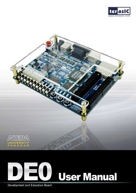
DE0 User Manual
DE0 User Manual
DE0 User Manual

Create successful ePaper yourself
Turn your PDF publications into a flip-book with our unique Google optimized e-Paper software.
Altera <strong>DE0</strong> Board<br />
Version 1.00 Copyright © 2009 Terasic Technologies
Altera <strong>DE0</strong> Board<br />
CONTENTS<br />
Chapter 1 <strong>DE0</strong> Package.....................................................................................................................1<br />
1.1 Package Contents .................................................................................................................1<br />
1.2 The <strong>DE0</strong> Board Assembly....................................................................................................2<br />
� Getting Help.........................................................................................................................2<br />
Chapter 2 Altera <strong>DE0</strong> Board.............................................................................................................3<br />
2.1 Layout and Components ......................................................................................................3<br />
2.2 Block Diagram of the <strong>DE0</strong> Board........................................................................................5<br />
2.3 Power-up the <strong>DE0</strong> Board .....................................................................................................7<br />
Chapter 3 <strong>DE0</strong> Control Panel ...........................................................................................................9<br />
3.1 Control Panel Setup .............................................................................................................9<br />
3.2 Controlling the LEDs and 7-Segment Displays................................................................. 11<br />
3.3 Switches and Buttons.........................................................................................................13<br />
3.4 SDRAM and Flash Controller and Programmer................................................................14<br />
3.5 PS2 Device.........................................................................................................................15<br />
3.6 SD CARD ..........................................................................................................................16<br />
3.7 VGA...................................................................................................................................17<br />
Chapter 4 Using the <strong>DE0</strong> Board .....................................................................................................19<br />
4.1 Configuring the Cyclone III FPGA....................................................................................19<br />
4.2 Using the LEDs and Switches............................................................................................22<br />
4.3 Using the 7-segment Displays............................................................................................25<br />
4.4 Clock Circuitry...................................................................................................................27<br />
4.5 Using the LCD Module......................................................................................................27<br />
4.6 Using the Expansion Header..............................................................................................30<br />
4.7 Using VGA ........................................................................................................................32<br />
4.8 RS-232 Serial Port .............................................................................................................35<br />
4.9 PS/2 Serial Port ..................................................................................................................36<br />
4.10 SD Card Socket..................................................................................................................37<br />
4.11 Using SDRAM and Flash ..................................................................................................37<br />
Chapter 5 Examples of Advanced Demonstrations ......................................................................42<br />
5.1 <strong>DE0</strong> Factory Configuration................................................................................................42<br />
5.2 SD Card..............................................................................................................................43<br />
5.3 VGA Color Pattern Demonstration....................................................................................47<br />
Chapter 6 Appendix .........................................................................................................................51<br />
6.1 Revision History ................................................................................................................51<br />
ii
Altera <strong>DE0</strong> Board<br />
6.2 Copyright Statement ..........................................................................................................51<br />
iii
Chapter 1<br />
<strong>DE0</strong> Package<br />
1<br />
<strong>DE0</strong> <strong>User</strong> <strong>Manual</strong><br />
The <strong>DE0</strong> package contains all the components needed to use the <strong>DE0</strong> board in conjunction with a<br />
computer that runs the Microsoft Windows software.<br />
1.1 Package Contents<br />
Figure 1.1 shows a photograph of the <strong>DE0</strong> package.<br />
Figure 1.1. The <strong>DE0</strong> package contents.
The <strong>DE0</strong> package includes:<br />
• The <strong>DE0</strong> board<br />
• USB Cable for FPGA programming and control<br />
• <strong>DE0</strong> System CD containing :<br />
2<br />
<strong>DE0</strong> <strong>User</strong> <strong>Manual</strong><br />
o Altera’s Quartus ® II Web Edition and the Nios ® II Embedded Design Suit Evaluation<br />
Edition software<br />
o the <strong>DE0</strong> documentation and supporting materials, including the <strong>User</strong> <strong>Manual</strong>, the<br />
Control Panel utility, reference designs and demonstrations, device datasheets,<br />
tutorials, and a set of laboratory exercises<br />
• Clear plastic cover for the board<br />
• 7.5 DC wall-mount power supply<br />
1.2 The <strong>DE0</strong> Board Assembly<br />
To assemble the included stands for the <strong>DE0</strong> board:<br />
• Assemble a rubber (silicon) cover, as shown in Figure 1.2, for each of the four copper stands<br />
on the <strong>DE0</strong> board<br />
• The clear plastic cover provides extra protection, and is mounted over the top of the board<br />
by using additional stands and screws<br />
� Getting Help<br />
Figure 1.2. The feet for the <strong>DE0</strong> board.<br />
Here are the addresses where you can get help if you encounter problems:
• Altera Corporation<br />
101 Innovation Drive<br />
San Jose, California, 95134 USA<br />
Email: university@altera.com<br />
• Terasic Technologies<br />
No. 356, Sec. 1, Fusing E. Rd.<br />
Jhubei City, HsinChu County, Taiwan, 302<br />
Email: support@terasic.com<br />
Web: <strong>DE0</strong>.terasic.com<br />
Chapter 2<br />
Altera <strong>DE0</strong> Board<br />
This chapter presents the features and design characteristics of the <strong>DE0</strong> board.<br />
2.1 Layout and Components<br />
3<br />
<strong>DE0</strong> <strong>User</strong> <strong>Manual</strong><br />
A photograph of the <strong>DE0</strong> board is shown in Figure 2.1. It depicts the layout of the board and<br />
indicates the location of the connectors and key components.
Power ON/OFF Switch<br />
16 x 2 LCD Interface<br />
Altera EPCS 4<br />
Configuration Device<br />
USB Blaster Circuit<br />
SDRAM (8 Mbytes)<br />
7 - Segment Display (4)<br />
RUN/PROG Switch for<br />
JTAG/AS Modes<br />
Power Supply Input<br />
USB Blaster Connector<br />
Triple 4 - bit VGA DAC PS/2 Port SD Card Socket<br />
Slide Switches (10) <strong>User</strong> LEDs (10)<br />
PushButton Switches (3)<br />
Figure 2.1. The <strong>DE0</strong> board.<br />
4<br />
<strong>DE0</strong> <strong>User</strong> <strong>Manual</strong><br />
RS - 232 Interface<br />
50 - MHz Oscillator<br />
Expansion Headers (2)<br />
Cyclone III EP3C16F484<br />
FLASH (4 Mbytes)<br />
The <strong>DE0</strong> board has many features that allow the user to implement a wide range of designed<br />
circuits, from simple circuits to various multimedia projects.<br />
The following hardware is provided on the <strong>DE0</strong> board:<br />
• Altera Cyclone ® III 3C16 FPGA device<br />
• Altera Serial Configuration device – EPCS4<br />
• USB Blaster (on board) for programming and user API control; both JTAG and Active Serial<br />
(AS) programming modes are supported<br />
• 8-Mbyte SDRAM<br />
• 4-Mbyte Flash memory<br />
• SD Card socket<br />
• 3 pushbutton switches<br />
• 10 toggle switches<br />
• 10 green user LEDs<br />
• 50-MHz oscillator for clock sources<br />
• VGA DAC (4-bit resistor network) with VGA-out connector
• RS-232 transceiver<br />
• PS/2 mouse/keyboard connector<br />
• Two 40-pin Expansion Headers<br />
2.2 Block Diagram of the <strong>DE0</strong> Board<br />
5<br />
<strong>DE0</strong> <strong>User</strong> <strong>Manual</strong><br />
Figure 2.2 gives the block diagram of the <strong>DE0</strong> board. To provide maximum flexibility for the user,<br />
all connections are made through the Cyclone IIII FPGA device. Thus, the user can configure the<br />
FPGA to implement any system design.<br />
<strong>User</strong> LEDs (10)<br />
PushButton Switches (3)<br />
Slide Switches (10)<br />
PS/2<br />
Expansion Headers (2)<br />
16X2 LCD Interface<br />
EPCS4<br />
Config<br />
Device<br />
EP3C16F484<br />
USB<br />
Blaster<br />
SDRAM (8 Mbytes)<br />
16X2 LCD Module<br />
Figure 2.2. Block diagram of the <strong>DE0</strong> board.<br />
Following is more detailed information about the blocks in Figure 2.2:<br />
Cyclone IIII 3C16 FPGA<br />
� 15,408 LEs<br />
� 56 M9K Embedded Memory Blocks<br />
� 504K total RAM bits<br />
� 56 embedded multipliers<br />
� 4 PLLs<br />
� 346 user I/O pins<br />
Flash (4 Mbytes)<br />
SD Card Socket<br />
Triple 4-bit VGA DAC<br />
7-Segment Display (4)<br />
RS-232 Transceiver
� FineLine BGA 484-pin package<br />
Built-in USB Blaster circuit<br />
SDRAM<br />
6<br />
<strong>DE0</strong> <strong>User</strong> <strong>Manual</strong><br />
� On-board USB Blaster for programming and user API (Application programming interface)<br />
control<br />
� Using the Altera EPM240 CPLD<br />
� One 8-Mbyte Single Data Rate Synchronous Dynamic RAM memory chip<br />
� Supports 16-bits data bus<br />
Flash memory<br />
� 4-Mbyte NOR Flash memory<br />
� Support Byte (8-bits)/Word (16-bits) mode<br />
SD card socket<br />
� Provides both SPI and SD 1-bit mod SD Card access<br />
Pushbutton switches<br />
� 3 pushbutton switches<br />
� Normally high; generates one active-low pulse when the switch is pressed<br />
Slide switches<br />
� 10 Slide switches<br />
� A switch causes logic 0 when in the DOWN position and logic 1 when in the UP position<br />
General <strong>User</strong> Interfaces<br />
� 10 Green color LEDs (Active high)<br />
� 4 seven-segment displays (Active low)<br />
� 16x2 LCD Interface (Not include LCD module)<br />
Clock inputs<br />
� 50-MHz oscillator<br />
VGA output<br />
� Uses a 4-bit resistor-network DAC<br />
� With 15-pin high-density D-sub connector<br />
� Supports up to 1280x1024 at 60-Hz refresh rate
Serial ports<br />
� One RS-232 port (Without DB-9 serial connector)<br />
7<br />
<strong>DE0</strong> <strong>User</strong> <strong>Manual</strong><br />
� One PS/2 port (Can be used through a PS/2 Y Cable to allow you to connect a keyboard and<br />
mouse to one port)<br />
Two 40-pin expansion headers<br />
� 72 Cyclone III I/O pins, as well as 8 power and ground lines, are brought out to two 40-pin<br />
expansion connectors<br />
� 40-pin header is designed to accept a standard 40-pin ribbon cable used for IDE hard drives<br />
2.3 Power-up the <strong>DE0</strong> Board<br />
The <strong>DE0</strong> board comes with a preloaded configuration bit stream to demonstrate some features of<br />
the board. This bit stream also allows users to see quickly if the board is working properly. To<br />
power-up the board perform the following steps:<br />
1. Connect the provided USB cable from the host computer to the USB Blaster connector on<br />
the <strong>DE0</strong> board. For communication between the host and the <strong>DE0</strong> board, it is necessary to<br />
install the Altera USB Blaster driver software. If this driver is not already installed on the<br />
host computer, it can be installed as explained in the tutorial Getting Started with Altera's<br />
<strong>DE0</strong> Board. This tutorial is available in the directory <strong>DE0</strong>\<strong>DE0</strong>_user_manual on the <strong>DE0</strong><br />
System CD-ROM.<br />
2. Connect the 7.5V adapter to the <strong>DE0</strong> board<br />
3. Connect a VGA monitor to the VGA port on the <strong>DE0</strong> board<br />
4. Turn the RUN/PROG switch on the left edge of the <strong>DE0</strong> board to RUN position; the<br />
PROG position is used only for the AS Mode programming<br />
5. Turn the power on by pressing the ON/OFF switch on the <strong>DE0</strong> board<br />
At this point you should observe the following:<br />
• All user LEDs are flashing<br />
• All 7-segment displays are cycling through the numbers 0 to F<br />
• The VGA monitor displays the image shown in Figure 2.3.
Figure 2.3. The default VGA output pattern.<br />
8<br />
<strong>DE0</strong> <strong>User</strong> <strong>Manual</strong>
Chapter 3<br />
<strong>DE0</strong> Control Panel<br />
9<br />
<strong>DE0</strong> <strong>User</strong> <strong>Manual</strong><br />
The <strong>DE0</strong> board comes with a Control Panel facility that allows users to access various components<br />
on the board from a host computer. The host computer communicates with the board through an<br />
USB connection. The facility can be used to verify the functionality of components on the board or<br />
be used as a debug tool while developing RTL code.<br />
This chapter first presents some basic functions of the Control Panel, then describes its structure in<br />
block diagram form, and finally describes its capabilities.<br />
3.1 Control Panel Setup<br />
The Control Panel Software Utility is located in the “<strong>DE0</strong>_Control_panel” folder in the <strong>DE0</strong><br />
System CD-ROM. To install it, just copy the whole folder to your host computer.<br />
To activate the Control Panel, perform the following steps:<br />
1. Make sure Quartus II and USB-Blaster Driver are installed successfully on your PC.<br />
2. Connect the supplied USB cable to the USB Blaster port, connect the 7.5V power supply,<br />
and turn the power switch ON<br />
3. Set the RUN/PROG switch to the RUN position<br />
4. Start the executable <strong>DE0</strong>_ControlPanel.exe on the host computer. The Control Panel user<br />
interface shown in Figure 3.1 will appear.<br />
5. When the control panel window appears, it will automatically download the bit<br />
stream file .sof into the FPGA. If any error message shows up as shown in Figure 3.2,<br />
please check steps 1 to 3 has been performed. Then, click Download Code button to<br />
program FPGA again. Note, the Control Panel will occupy the USB port until you close<br />
that port; you cannot use Quartus II to download a configuration file into the FPGA until<br />
you close the USB port.<br />
6. The Control Panel is now ready to be use; experiment by setting the value of the LEDs<br />
display and observe the result on the <strong>DE0</strong> board.
Figure 3.1. The <strong>DE0</strong> Control Panel.<br />
Figure 3.2. The error message of the <strong>DE0</strong> Control Panel.<br />
10<br />
<strong>DE0</strong> <strong>User</strong> <strong>Manual</strong><br />
The concept of the <strong>DE0</strong> Control Panel is illustrated in Figure 3.3. The “Control Codes” that perform<br />
the control functions is implemented in the FPGA board. It communicates with the Control Panel<br />
window, which is active on the host computer, via the USB Blaster link. The graphical interface is<br />
used to issue commands to the control codes. It handles all requests and performs data transfers<br />
between the computer and the <strong>DE0</strong> board.
JTAG<br />
Blaster<br />
Hardware<br />
FPGA/ SOPC<br />
NIOS II<br />
TIMER<br />
JTAG<br />
System Interconnect Fabric<br />
Avalon- MM<br />
Tristate Bridge<br />
11<br />
SEG7 Controller<br />
SDRAM Controller<br />
PS2 Controller<br />
VGA Controller<br />
PIO Controller<br />
Figure 3.3. The <strong>DE0</strong> Control Panel concept.<br />
Flash<br />
Controller<br />
<strong>DE0</strong> <strong>User</strong> <strong>Manual</strong><br />
7-SEG Display<br />
SDRAM<br />
PS2 Keyboard<br />
VGA<br />
LED/Button/<br />
Switch/ Seg7/<br />
SD- Card<br />
The <strong>DE0</strong> Control Panel can be used to light up the LEDs, change the values displayed on 7-segment,<br />
monitor buttons/switches status, read/write the SDRAM and Flash Memory, read data from a PS/2<br />
keyboard, output color pattern to LCD monitor via VGA connector, and read SD-CARD<br />
specification information. The feature of reading/writing a word or an entire file from/to the Flash<br />
Memory allows the user to develop multimedia application (Flash Picture Viewer) without worrying<br />
about how to build a Memory Programmer.<br />
3.2 Controlling the LEDs and 7-Segment Displays<br />
A simple function of the Control Panel is to allow setting the values displayed on LEDs and the<br />
7-segment displays.<br />
Choosing the LED tab leads to the window in Figure 3.4. Here, you can directly turn the individual<br />
LEDs on or off by selecting them individually or by clicking “Light All” or “Unlight All”.<br />
Flash
Figure 3.4. Controlling LEDs<br />
12<br />
<strong>DE0</strong> <strong>User</strong> <strong>Manual</strong><br />
Choosing the 7-SEG tab leads to the window in Figure 3.5. In the tab sheet, directly use the<br />
Up-Down control and Dot Check box to specified desired patterns, the 7-SEG patterns on the board<br />
will be updated immediately.<br />
Figure 3.5. Controlling 7-SEG display.
13<br />
<strong>DE0</strong> <strong>User</strong> <strong>Manual</strong><br />
The ability to set arbitrary values into simple display devices is not needed in typical design<br />
activities. However, it gives the user a simple mechanism for verifying that these devices are<br />
functioning correctly in case a malfunction is suspected. Thus, it can be used for troubleshooting<br />
purposes.<br />
3.3 Switches and Buttons<br />
Choosing the Button tab leads to the window in Figure 3.6. The function is designed to monitor the<br />
status of switches and buttons in real time and show the status in a graphical user interface. It can be<br />
used to verify the functionality of the switches and buttons.<br />
Press the Start button to start button/switch status monitoring process, and button caption is<br />
changed from Start to Stop. In the monitoring process, the status of buttons and switches on the<br />
board is shown in the GUI window and updated in real time. Press Stop to end the monitoring<br />
process.<br />
Figure 3.6. Monitoring switches and buttons.<br />
The ability to check the status of button and switch is not needed in typical design activities.<br />
However, it provides users a simple mechanism for verifying if the buttons and switches are<br />
functioning correctly. Thus, it can be used for troubleshooting purposes.
3.4 SDRAM and Flash Controller and Programmer<br />
14<br />
<strong>DE0</strong> <strong>User</strong> <strong>Manual</strong><br />
The Control Panel can be used to write/read data to/from the SDRAM and FLASH chips on the<br />
<strong>DE0</strong> board. Click on the Memory tab and select “SDRAM” to reach the window in Figure 3.7.<br />
Please note to erase the flash memory before writing data to it.<br />
Figure 3.7. Accessing the SDRAM<br />
A 16-bit word can be written into the SDRAM by entering the address of the desired location,<br />
specifying the data to be written, and pressing the Write button. Contents of the location can be<br />
read by pressing the Read button. Figure 3.7 depicts the result of writing the hexadecimal value<br />
7eff into location 000000, followed by reading the same location.<br />
The Sequential Write function of the Control Panel is used to write the contents of a file into the<br />
SDRAM as follows:<br />
1. Specify the starting address in the Address box.<br />
2. Specify the number of bytes to be written in the Length box. If the entire file is to be<br />
loaded, then a checkmark may be placed in the File Length box instead of giving the<br />
number of bytes.<br />
3. To initiate the writing of data, click on the Write a File to Memory button.<br />
4. When the Control Panel responds with the standard Windows dialog box asking for the<br />
source file, specify the desired file in the usual manner.
15<br />
<strong>DE0</strong> <strong>User</strong> <strong>Manual</strong><br />
The Control Panel also supports loading files with a .hex extension. Files with a .hex extension are<br />
ASCII text files that specify memory values using ASCII characters to represent hexadecimal<br />
values. For example, a file containing the line<br />
0123456789ABCDEF<br />
defines four 8-bit values: 01, 23, 45, 67, 89, AB, CD, EF. These values will be loaded consecutively<br />
into the memory.<br />
The Sequential Read function is used to read the contents of the SDRAM and place them into a file<br />
as follows:<br />
1. Specify the starting address in the Address box.<br />
2. Specify the number of bytes to be copied into the file in the Length box. If the entire<br />
contents of the SDRAM are to be copied (which involves all 8 Mbytes), then place a<br />
checkmark in the Entire Memory box.<br />
3. Press Load Memory Content to a File button.<br />
4. When the Control Panel responds with the standard Windows dialog box asking for the<br />
destination file, specify the desired file in the usual manner.<br />
<strong>User</strong>s can use the similar way to access the Flash. Please note that users need to erase the flash<br />
before writing data to it.<br />
3.5 PS2 Device<br />
The Control Panel provides users a tool to receive the inputs from a PS2 keyboard in real time. The<br />
received scan-codes are translated to ASCII code and displayed in the control window. Only visible<br />
ASCII codes are displayed. For control key, only “Carriage Return/ENTER” key is implemented.<br />
This function can be used to verify the functionality of the PS2 Interface. Please follow the steps<br />
below to exercise the PS2 device:<br />
1. Choosing the PS2 tab leads to the window in Figure 3.8.<br />
2. Plug a PS2 Keyboard to the FPGA board. Then,<br />
3. Press the Start button to start PS2Keyboard input receiving process; Button caption is<br />
changed from Start to Stop.<br />
4. In the receiving process, users can start to press the attached keyboard. The input data will<br />
be displayed in the control window in real time. Press Stop to terminate the monitoring<br />
process.
3.6 SD CARD<br />
Figure 3.8. Reading the PS2 Keyboards<br />
16<br />
<strong>DE0</strong> <strong>User</strong> <strong>Manual</strong><br />
The function is designed to read the identification and specification of the SD card. The 1-bit SD<br />
MODE is used to access the SD card. This function can be used to verify the functionality of<br />
SD-CARD Interface. Follow the steps below to exercise the SD card:<br />
1. Choosing the SD-CARD tab leads to the window in Figure 3.9.<br />
2. Insert a SD card to the <strong>DE0</strong> board, then press the Read button to read the SD card. The SD<br />
card’s identification and specification will be displayed in the control window.
3.7 VGA<br />
Figure 3.9. Reading the SD card Identification and Specification<br />
17<br />
<strong>DE0</strong> <strong>User</strong> <strong>Manual</strong><br />
<strong>DE0</strong> control panel provides VGA pattern function that allows users to output color pattern to<br />
LCD/CRT monitor using the <strong>DE0</strong> FPGA board. Please follow the steps below to generate the VGA<br />
pattern function:<br />
1. Choosing the VGA tab leads to the window in Figure 3.10.<br />
2. Plug a D-sub cable to the VGA connector of the <strong>DE0</strong> board and LCD/CRT monitor.<br />
3. The LCD/CRT monitor will display the same color pattern on the control panel window.<br />
4. Click the drop down menu shown in Figure 3.10 where you can output the selected color<br />
individually.
Figure 3.10. Controlling VGA display<br />
18<br />
<strong>DE0</strong> <strong>User</strong> <strong>Manual</strong>
Chapter 4<br />
Using the <strong>DE0</strong> Board<br />
19<br />
<strong>DE0</strong> <strong>User</strong> <strong>Manual</strong><br />
This chapter gives instructions for using the <strong>DE0</strong> board and describes each of its I/O devices.<br />
4.1 Configuring the Cyclone III FPGA<br />
The procedure for downloading a circuit from a host computer to the <strong>DE0</strong> board is described in the<br />
tutorial Getting Started with Altera's <strong>DE0</strong> Board. This tutorial is found in the user_manaul folder on<br />
the <strong>DE0</strong> System CD-ROM. The user is encouraged to read the tutorial first, and to treat the<br />
information below as a short reference.<br />
The <strong>DE0</strong> board contains a serial EEPROM chip that stores configuration data for the Cyclone III<br />
FPGA. This configuration data is automatically loaded from the EEPROM chip into the FPGA each<br />
time power is applied to the board. Using the Quartus II software, it is possible to reprogram the<br />
FPGA at any time, and it is also possible to change the non-volatile data that is stored in the serial<br />
EEPROM chip. Both types of programming methods are described below.<br />
1. JTAG programming: In this method of programming, named after the IEEE standards Joint<br />
Test Action Group, the configuration bit stream is downloaded directly into the Cyclone III<br />
FPGA. The FPGA will retain this configuration as long as power is applied to the board;<br />
the configuration is lost when the power is turned off.<br />
2. AS programming: In this method, called Active Serial programming, the configuration bit<br />
stream is downloaded into the Altera EPCS4 serial EEPROM chip. It provides non-volatile<br />
storage of the bit stream, so that the information is retained even when the power supply to<br />
the <strong>DE0</strong> board is turned off. When the board's power is turned on, the configuration data in<br />
the EPCS4 device is automatically loaded into the Cyclone III FPGA.<br />
The sections below describe the steps used to perform both JTAG and AS programming. For both<br />
methods the <strong>DE0</strong> board is connected to a host computer via a USB cable. Using this connection, the<br />
board will be identified by the host computer as an Altera USB Blaster device. The process for<br />
installing on the host computer the necessary software device driver that communicates with the<br />
USB Blaster is described in the tutorial Getting Started with Altera's <strong>DE0</strong> Board. This tutorial is<br />
available on the <strong>DE0</strong> System CD-ROM.
Configuring the FPGA in JTAG Mode<br />
20<br />
<strong>DE0</strong> <strong>User</strong> <strong>Manual</strong><br />
Figure 4.1 illustrates the JTAG configuration setup. To download a configuration bit stream into the<br />
Cyclone III FPGA, perform the following steps:<br />
• Ensure that power is applied to the <strong>DE0</strong> board<br />
• Connect the supplied USB cable to the USB Blaster port on the <strong>DE0</strong> board (see Figure 2.1)<br />
• Configure the JTAG programming circuit by setting the RUN/PROG switch (see Figure 4.2)<br />
to the RUN position.<br />
• The FPGA can now be programmed by using the Quartus II Programmer module to select a<br />
configuration bit stream file with the .sof filename extension<br />
Quartus II<br />
Programmer<br />
USB Blaster Circuit<br />
MAX II<br />
EPM240<br />
PROG/RUN<br />
¨RUN¨<br />
JTAG UART<br />
JTAG Config Signals<br />
Figure 4.1. The JTAG configuration scheme<br />
Figure 4.2. The RUN/PROG switch (SW2) is set in JTAG mode<br />
Configuring the EPCS4 in AS Mode<br />
Figure 4.3 illustrates the AS configuration set up. To download a configuration bit stream into the<br />
EPCS4 serial EEPROM device, perform the following steps:<br />
• Ensure that power is applied to the <strong>DE0</strong> board
21<br />
<strong>DE0</strong> <strong>User</strong> <strong>Manual</strong><br />
• Connect the supplied USB cable to the USB Blaster port on the <strong>DE0</strong> board (see Figure 2.1)<br />
• Configure the JTAG programming circuit by setting the RUN/PROG switch (see Figure 4.4)<br />
to the PROG position.<br />
• The EPCS4 chip can now be programmed by using the Quartus II Programmer module to<br />
select a configuration bit stream file with the .pof filename extension<br />
• Once the programming operation is finished, set the RUN/PROG switch back to the RUN<br />
position and then reset the board by turning the power switch off and back on; this action<br />
causes the new configuration data in the EPCS4 device to be loaded into the FPGA chip.<br />
Quartus II<br />
Programmer<br />
AS Mode<br />
USB Blaster Circuit<br />
MAX II<br />
EPM240<br />
PROG/RUN<br />
¨PROG¨<br />
AS Mode<br />
Config<br />
Auto Power-on<br />
Config<br />
EPCS4<br />
Serial<br />
Configuration<br />
Device<br />
Figure 4.3. The AS configuration scheme<br />
Figure 4.4. The RUN/PROG switch(SW2) is set in AS mode
22<br />
<strong>DE0</strong> <strong>User</strong> <strong>Manual</strong><br />
In addition to its use for JTAG and AS programming, the USB Blaster port on the <strong>DE0</strong> board can<br />
also be used to control some of the board's features remotely from a host computer. Details that<br />
describe this method of using the USB Blaster port are given in Chapter 3.<br />
4.2 Using the LEDs and Switches<br />
The <strong>DE0</strong> board provides three pushbutton switches. The three outputs called BUTTON0, BUTTON<br />
1, and BUTTON2 are connected directly to the Cyclone III FPGA. Each switch provides a high<br />
logic level (3.3 volts) when it is not pressed, and provides a low logic level (0 volts) when<br />
depressed.<br />
There are also 10 slide switches (sliders) on the <strong>DE0</strong> board. These switches are not debounced, and<br />
are intended for use as level-sensitive data inputs to a circuit. Each switch is connected directly to a<br />
pin on the Cyclone III FPGA. When a switch is in the DOWN position (closest to the edge of the<br />
board) it provides a low logic level (0 volts) to the FPGA, and when the switch is in the UP position<br />
it provides a high logic level (3.3 volts).<br />
There are 10 user-controllable LEDs on the <strong>DE0</strong> board. Each LED is driven directly by a pin on the<br />
Cyclone III FPGA; driving its associated pin to a high logic level turns the LED on, and driving the<br />
pin low turns it off. Figure 4.5 and Figure 4.6 show the connections between the push buttons, slide<br />
switches, and Cyclone III FPGA<br />
A list of the pin names on the Cyclone III FPGA that are connected to the toggle switches is given<br />
in Table 4.1. Similarly, the pins used to connect to the pushbutton switches and LEDs are displayed<br />
in Table 4.2 and Table 4.3, respectively.<br />
BUTTON0<br />
BUTTON1<br />
BUTTON2<br />
3.3V<br />
Figure 4.5. Connections between the pushbutton and Cyclone III FPGA<br />
H2<br />
G3<br />
F1
D2 E4 E3 H7 J7 G5 G4 H6 H5 J6<br />
SW9<br />
SW8<br />
SW7<br />
SW6<br />
SW5<br />
SW4<br />
23<br />
SW3<br />
SW2<br />
SW1<br />
SW0<br />
<strong>DE0</strong> <strong>User</strong> <strong>Manual</strong><br />
Logic ``1``<br />
Logic``0``<br />
Figure 4.6. Connections between the toggle switches and Cyclone III FPGA<br />
J1<br />
J2<br />
J3<br />
H1<br />
F2<br />
E1<br />
C1<br />
C2<br />
B2<br />
B1<br />
LEDG0<br />
LEDG1<br />
LEDG2<br />
LEDG3<br />
LEDG4<br />
LEDG5<br />
LEDG6<br />
LEDG7<br />
LEDG8<br />
LEDG9<br />
LEDG0<br />
LEDG1<br />
LEDG2<br />
LEDG3<br />
LEDG4<br />
LEDG5<br />
LEDG6<br />
LEDG7<br />
LEDG8<br />
LEDG9<br />
Figure 4.7. Connections between the LEDs and Cyclone III FPGA
Table 4.1. Pin assignments for the slide switches<br />
Signal Name FPGA Pin No. Description<br />
SW[0] PIN_J6 Slide Switch[0]<br />
SW[1] PIN_H5 Slide Switch[1]<br />
SW[2] PIN_H6 Slide Switch[2]<br />
SW[3] PIN_G4 Slide Switch[3]<br />
SW[4] PIN_G5 Slide Switch[4]<br />
SW[5] PIN_J7 Slide Switch[5]<br />
SW[6] PIN_H7 Slide Switch[6]<br />
SW[7] PIN_E3 Slide Switch[7]<br />
SW[8] PIN_E4 Slide Switch[8]<br />
SW[9] PIN_D2 Slide Switch[9]<br />
Table 4.2. Pin assignments for the pushbutton switches<br />
Signal Name FPGA Pin No. Description<br />
BUTTON [0] PIN_ H2 Pushbutton[0]<br />
BUTTON [1] PIN_ G3 Pushbutton[1]<br />
BUTTON [2] PIN_ F1 Pushbutton[2]<br />
Table 4.3. Pin assignments for the LEDs<br />
Signal Name FPGA Pin No. Description<br />
LEDG[0] PIN_J1 LED Green[0]<br />
LEDG[1] PIN_J2 LED Green[1]<br />
LEDG[2] PIN_J3 LED Green[2]<br />
LEDG[3] PIN_H1 LED Green[3]<br />
LEDG[4] PIN_F2 LED Green[4]<br />
LEDG[5] PIN_E1 LED Green[5]<br />
LEDG[6] PIN_C1 LED Green[6]<br />
LEDG[7] PIN_C2 LED Green[7]<br />
LEDG[8] PIN_B2 LED Green[8]<br />
LEDG[9] PIN_B1 LED Green[9]<br />
24<br />
<strong>DE0</strong> <strong>User</strong> <strong>Manual</strong>
4.3 Using the 7-segment Displays<br />
25<br />
<strong>DE0</strong> <strong>User</strong> <strong>Manual</strong><br />
The <strong>DE0</strong> board has four 7-segment displays. These displays are arranged into two pairs and a group<br />
of four, with the intent of displaying numbers of various sizes. As indicated in Figure 4.8, the seven<br />
segments are connected to pins on the Cyclone III FPGA. Applying a low logic level to a segment<br />
causes it to light up, and applying a high logic level turns it off.<br />
Each segment in a display is identified by an index from 0 to 6, with the positions given in Figure<br />
4.9. In addition, the decimal point is identified as DP. Table 4.4 shows the connections between the<br />
FPGA pins to the 7-segment displays.<br />
HEX0_D5<br />
HEX0_D4<br />
HEX0<br />
HEX0_D0<br />
HEX0_D6<br />
HEX0_D3<br />
HEX0_D1<br />
HEX0_D2<br />
HEX0_DP<br />
HEX0_D0<br />
HEX0_D1<br />
HEX0_D2<br />
HEX0_D3<br />
HEX0_D4<br />
HEX0_D5<br />
HEX0_D6<br />
HEX0_DP<br />
E11<br />
F11<br />
H12<br />
H13<br />
Figure 4.8. Connections between the 7-segment displays and Cyclone III FPGA<br />
5<br />
4<br />
0<br />
6<br />
3<br />
1<br />
2<br />
DP<br />
G12<br />
F12<br />
F13<br />
D13<br />
Figure 4.9. Position and index of each segment in a 7-segment display
Table 4.4. Pin assignments for the 7-segment displays.<br />
Signal Name FPGA Pin No. Description<br />
HEX0_D[0] PIN_E11 Seven Segment Digit 0[0]<br />
HEX0_D[1] PIN_F11 Seven Segment Digit 0[1]<br />
HEX0_D[2] PIN_H12 Seven Segment Digit 0[2]<br />
HEX0_D[3] PIN_H13 Seven Segment Digit 0[3]<br />
HEX0_D[4] PIN_G12 Seven Segment Digit 0[4]<br />
HEX0_D[5] PIN_F12 Seven Segment Digit 0[5]<br />
HEX0_D[6] PIN_F13 Seven Segment Digit 0[6]<br />
HEX0_DP PIN_D13 Seven Segment Decimal Point 0<br />
HEX1_D[0] PIN_A13 Seven Segment Digit 1[0]<br />
HEX1_D[1] PIN_B13 Seven Segment Digit 1[1]<br />
HEX1_D[2] PIN_C13 Seven Segment Digit 1[2]<br />
HEX1_D[3] PIN_A14 Seven Segment Digit 1[3]<br />
HEX1_D[4] PIN_B14 Seven Segment Digit 1[4]<br />
HEX1_D[5] PIN_E14 Seven Segment Digit 1[5]<br />
HEX1_D[6] PIN_A15 Seven Segment Digit 1[6]<br />
HEX1_DP PIN_B15 Seven Segment Decimal Point 1<br />
HEX2_D[0] PIN_D15 Seven Segment Digit 2[0]<br />
HEX2_D[1] PIN_A16 Seven Segment Digit 2[1]<br />
HEX2_D[2] PIN_B16 Seven Segment Digit 2[2]<br />
HEX2_D[3] PIN_E15 Seven Segment Digit 2[3]<br />
HEX2_D[4] PIN_A17 Seven Segment Digit 2[4]<br />
HEX2_D[5] PIN_B17 Seven Segment Digit 2[5]<br />
HEX2_D[6] PIN_F14 Seven Segment Digit 2[6]<br />
HEX2_DP PIN_A18 Seven Segment Decimal Point 2<br />
HEX3_D[0] PIN_B18 Seven Segment Digit 3[0]<br />
HEX3_D[1] PIN_F15 Seven Segment Digit 3[1]<br />
HEX3_D[2] PIN_A19 Seven Segment Digit 3[2]<br />
HEX3_D[3] PIN_B19 Seven Segment Digit 3[3]<br />
HEX3_D[4] PIN_C19 Seven Segment Digit 3[4]<br />
HEX3_D[5] PIN_D19 Seven Segment Digit 3[5]<br />
HEX3_D[6] PIN_G15 Seven Segment Digit 3[6]<br />
HEX3_DP PIN_G16 Seven Segment Decimal Point 3<br />
26<br />
<strong>DE0</strong> <strong>User</strong> <strong>Manual</strong>
4.4 Clock Circuitry<br />
27<br />
<strong>DE0</strong> <strong>User</strong> <strong>Manual</strong><br />
The <strong>DE0</strong> board includes a 50 MHz clock signals. This clock signal is connected to the FPGA that<br />
are used for clocking the user logic. In addition, all these clock inputs are connected to the phase<br />
lock loops (PLL) clock input pin of the FPGA allowed users can use these clocks as a source clock<br />
for the PLL circuit.<br />
The clock distribution on the <strong>DE0</strong> board is shown in Figure 4.10. The associated pin assignments<br />
for clock inputs to FPGA I/O pins are listed in Table 4.5.<br />
50 MHz<br />
OSC<br />
CLOCK _ 50<br />
CLOCK _ 50_ 2<br />
Figure 4.10. Block diagram of the clock distribution.<br />
Table 4.5. Pin assignments for the clock inputs.<br />
Signal Name FPGA Pin No. Description<br />
CLOCK_50 PIN_G21 50 MHz clock input<br />
CLOCK_50_2 PIN_B12 50 MHz clock input<br />
4.5 Using the LCD Module<br />
G 21 (CLK 4 )<br />
B 12 (CLK 9 )<br />
( CLK 12 )<br />
CLK 13 )<br />
AB<br />
12<br />
( AA<br />
PLL1 _ CLKOUTn )<br />
( CLK 14 )<br />
GPIO 0 _ CLKIN 0<br />
GPIO 0 _ CLKIN 1<br />
GPIO 0_CLKOUT 0<br />
GPIO 0_CLKOUT 1<br />
GPIO 1 _ CLKIN 0<br />
GPIO 1 _ CLKIN 1<br />
GPIO 1 _ CLKOUT 0<br />
GPIO 1 _ CLKOUT 1<br />
GPIO 0 ( J4 )<br />
GPIO 1 ( J 5)<br />
The <strong>DE0</strong> board provides a 2x16 LCD interface. In order to use the LCD interface, users are<br />
required to solder a LCD module onto the <strong>DE0</strong> board shown in Figure 4.11. The detailed<br />
component reference is listed in Table 4.6. Also, users can buy this module from Terasic website<br />
12<br />
( PLL1 _ CLKOUT p ) AB 3<br />
(<br />
AA<br />
3<br />
11<br />
( CLK 15 ) AB 11<br />
PLL 4_CLKOUTn<br />
AA<br />
) 16<br />
( ( PLL4 _ CLKOUT p ) R T6<br />
1<br />
3<br />
19<br />
21<br />
1<br />
3<br />
19<br />
21
(http://de0.terasic.com).<br />
Table 4.6. The listed information on the LCD module<br />
Board<br />
Reference<br />
28<br />
Description<br />
J2 2x16 LCD Module<br />
<strong>DE0</strong> <strong>User</strong> <strong>Manual</strong><br />
The LCD module has built-in fonts and can be used to display text by sending appropriate<br />
commands to the display controller, which is called HD44780. Detailed information for using the<br />
display is available in its datasheet, which can be found on the manufacturer's web site, and from<br />
the Datasheet/LCD folder on the <strong>DE0</strong> System CD-ROM. A schematic diagram of the LCD module<br />
showing connections to the Cyclone III FPGA is given in Figure 4.12. The associated pin<br />
assignments appear in Table 4.7.<br />
Figure 4.11. LCD module on <strong>DE0</strong> board
F21 D22 D21 C22 C21 B22 B21 D20 C20 E21 F22 E22<br />
LCD_BLON<br />
LCD_DATA0<br />
LCD_DATA1<br />
LCD_DATA2<br />
LCD_DATA3<br />
LCD_DATA4<br />
2 X 16 LCD Module<br />
Figure 4.12. Connections between the LCD module and Cyclone III FPGA<br />
29<br />
LCD_DATA5<br />
LCD_DATA6<br />
LCD_DATA7<br />
LCD_EN<br />
Table 4.7. Pin assignments for the LCD module<br />
Signal Name FPGA Pin No. Description<br />
LCD_DATA[0] PIN_D22 LCD Data[0]<br />
LCD_DATA[1] PIN_D21 LCD Data[1]<br />
LCD_DATA[2] PIN_C22 LCD Data[2]<br />
LCD_DATA[3] PIN_C21 LCD Data[3]<br />
LCD_DATA[4] PIN_B22 LCD Data[4]<br />
LCD_DATA[5] PIN_B21 LCD Data[5]<br />
LCD_DATA[6] PIN_D20 LCD Data[6]<br />
LCD_DATA[7] PIN_C20 LCD Data[7]<br />
LCD_RW PIN_E22 LCD Read/Write Select, 0 = Write, 1 = Read<br />
LCD_EN PIN_E21 LCD Enable<br />
LCD_RS PIN_F22 LCD Command/Data Select, 0 = Command, 1 = Data<br />
LCD_BLON PIN_F21 LCD Back Light ON/OFF<br />
LCD_RS<br />
LCD_RW<br />
<strong>DE0</strong> <strong>User</strong> <strong>Manual</strong><br />
Note that some LCD modules do not have backlight. Therefore the LCD_BLON signal should not<br />
be used in users’ design projects.
4.6 Using the Expansion Header<br />
30<br />
<strong>DE0</strong> <strong>User</strong> <strong>Manual</strong><br />
The <strong>DE0</strong> Board provides two 40-pin expansion headers. Each header connects directly to 36 pins of<br />
the Cyclone III FPGA, and also provides DC +5V (VCC5), DC +3.3V (VCC33), and two GND pins.<br />
Among these 36 I/O pins, 4 pins are connected to the PLL clock input and output pins of the FPGA<br />
allowing the expansion daughter cards to access the PLL blocks in the FPGA.<br />
Finally, Figure 4.13 shows the related schematics. The figure shows the protection circuitry for only<br />
two of the pins on each header, but this circuitry is included for all 72 data pins. Table 4.8 gives the<br />
pin assignments.<br />
[AB12] GPIO0_CLKIN0<br />
[AA12] GPIO0_CLKIN1<br />
[AA15] GPIO0_D2<br />
[AA14] GPIO0_D4<br />
[AB13] GPIO0_D6<br />
5V<br />
[AB10] GPIO0_D8<br />
[AB8] GPIO0_D10<br />
[AB5] GPIO0_D12<br />
[AB3] GPIO0_CLKOUT0<br />
[AA3] GPIO0_CLKOUT1<br />
[V14] GPIO0_D16<br />
[Y13] GPIO0_D18<br />
[U13] GPIO0_D20<br />
3.3V<br />
[R10] GPIO0_D22<br />
[Y10] GPIO0_D24<br />
[T8] GPIO0_D26<br />
[W7] GPIO0_D28<br />
[V5] GPIO0_D30<br />
(GPIO 0)<br />
J4<br />
1<br />
3<br />
5<br />
7<br />
9<br />
11<br />
13<br />
15<br />
17<br />
19<br />
21<br />
23<br />
25<br />
27<br />
29<br />
31<br />
33<br />
35<br />
37<br />
39<br />
2<br />
4<br />
6<br />
8<br />
10<br />
12<br />
14<br />
16<br />
18<br />
20<br />
22<br />
24<br />
26<br />
28<br />
30<br />
32<br />
34<br />
36<br />
38<br />
40<br />
GPIO0_D0 [AB16]<br />
GPIO0_D1 [AA16]<br />
GPIO0_D3 [AB15]<br />
GPIO0_D5 [AB14]<br />
GPIO0_D7 [AA13]<br />
GND<br />
GPIO0_D9 [AA10]<br />
GPIO0_D11 [AA8]<br />
GPIO0_D13 [AA5]<br />
GPIO0_D14 [AB4]<br />
GPIO0_D15 [AA4]<br />
GPIO0_D17 [U14]<br />
GPIO0_D19 [W13]<br />
GPIO0_D21 [V12]<br />
GND<br />
GPIO0_D23 [V11]<br />
GPIO0_D25 [W10]<br />
GPIO0_D27 [V8]<br />
GPIO0_D29 [W6]<br />
GPIO0_D31 [U7]<br />
[AB11] GPIO1_CLKIN0<br />
[AA11] GPIO1_CLKIN1<br />
[AA19] GPIO1_D2<br />
[AB18] GPIO1_D4<br />
[AA17] GPIO1_D6<br />
5V<br />
[Y17] GPIO1_D8<br />
[U15] GPIO1_D10<br />
[W15] GPIO1_D12<br />
[R16] GPIO1_CLKOUT0<br />
[T16] GPIO1_CLKOUT1<br />
[AA7] GPIO1_D16<br />
[T14] GPIO1_D18<br />
[U12] GPIO1_D20<br />
3.3V<br />
[R11] GPIO1_D22<br />
[U10] GPIO1_D24<br />
[U9] GPIO1_D26<br />
[Y7] GPIO1_D28<br />
[V6] GPIO1_D30<br />
Figure 4.13. I/O distribution of the expansion headers<br />
Table 4.8. Pin assignments for the expansion headers.<br />
Signal Name FPGA Pin No. Description<br />
GPIO0_D[0] PIN_AB16 GPIO Connection 0 IO[0]<br />
GPIO0_D[1] PIN_AA16 GPIO Connection 0 IO[1]<br />
GPIO0_D[2] PIN_AA15 GPIO Connection 0 IO[2]<br />
GPIO0_D[3] PIN_AB15 GPIO Connection 0 IO[3]<br />
GPIO0_D[4] PIN_AA14 GPIO Connection 0 IO[4]<br />
GPIO0_D[5] PIN_AB14 GPIO Connection 0 IO[5]<br />
GPIO0_D[6] PIN_AB13 GPIO Connection 0 IO[6]<br />
(GPIO 1)<br />
J5<br />
1<br />
3<br />
5<br />
7<br />
9<br />
11<br />
13<br />
15<br />
17<br />
19<br />
21<br />
23<br />
25<br />
27<br />
29<br />
31<br />
33<br />
35<br />
37<br />
39<br />
2<br />
4<br />
6<br />
8<br />
10<br />
12<br />
14<br />
16<br />
18<br />
20<br />
22<br />
24<br />
26<br />
28<br />
30<br />
32<br />
34<br />
36<br />
38<br />
40<br />
GPIO1_D0 [AA20]<br />
GPIO1_D1 [AB20]<br />
GPIO1_D3 [AB19]<br />
GPIO1_D5 [AA18]<br />
GPIO1_D7 [AB17]<br />
GND<br />
GPIO1_D9 [W17]<br />
GPIO1_D11 [T15]<br />
GPIO1_D13 [V15]<br />
GPIO1_D14 [AB9]<br />
GPIO1_D15 [AA9]<br />
GPIO1_D17 [AB7]<br />
GPIO1_D19 [R14]<br />
GPIO1_D21 [T12]<br />
GND<br />
GPIO1_D23 [R12]<br />
GPIO1_D25 [T10]<br />
GPIO1_D27 [T9]<br />
GPIO1_D29 [U8]<br />
GPIO1_D31 [V7]
GPIO0_D[7] PIN_AA13 GPIO Connection 0 IO[7]<br />
GPIO0_D[8] PIN_AB10 GPIO Connection 0 IO[8]<br />
GPIO0_D[9] PIN_AA10 GPIO Connection 0 IO[9]<br />
GPIO0_D[10] PIN_AB8 GPIO Connection 0 IO[10]<br />
GPIO0_D[11] PIN_AA8 GPIO Connection 0 IO[11]<br />
GPIO0_D[12] PIN_AB5 GPIO Connection 0 IO[12]<br />
GPIO0_D[13] PIN_AA5 GPIO Connection 0 IO[13]<br />
GPIO0_D[14] PIN_AB4 GPIO Connection 0 IO[14]<br />
GPIO0_D[15] PIN_AA4 GPIO Connection 0 IO[15]<br />
GPIO0_D[16] PIN_V14 GPIO Connection 0 IO[16]<br />
GPIO0_D[17] PIN_U14 GPIO Connection 0 IO[17]<br />
GPIO0_D[18] PIN_Y13 GPIO Connection 0 IO[18]<br />
GPIO0_D[19] PIN_W13 GPIO Connection 0 IO[19]<br />
GPIO0_D[20] PIN_U13 GPIO Connection 0 IO[20]<br />
GPIO0_D[21] PIN_V12 GPIO Connection 0 IO[21]<br />
GPIO0_D[22] PIN_R10 GPIO Connection 0 IO[22]<br />
GPIO0_D[23] PIN_V11 GPIO Connection 0 IO[23]<br />
GPIO0_D[24] PIN_Y10 GPIO Connection 0 IO[24]<br />
GPIO0_D[25] PIN_W10 GPIO Connection 0 IO[25]<br />
GPIO0_D[26] PIN_T8 GPIO Connection 0 IO[26]<br />
GPIO0_D[27] PIN_V8 GPIO Connection 0 IO[27]<br />
GPIO0_D[28] PIN_W7 GPIO Connection 0 IO[28]<br />
GPIO0_D[29] PIN_W6 GPIO Connection 0 IO[29]<br />
GPIO0_D[30] PIN_V5 GPIO Connection 0 IO[30]<br />
GPIO0_D[31] PIN_U7 GPIO Connection 0 IO[31]<br />
GPIO0_CLKIN[0] PIN_AB12 GPIO Connection 0 PLL In<br />
GPIO0_CLKIN[1] PIN_AA12 GPIO Connection 0 PLL In<br />
GPIO0_CLKOUT[0] PIN_AB3 GPIO Connection 0 PLL Out<br />
GPIO0_CLKOUT[1] PIN_AA3 GPIO Connection 0 PLL Out<br />
GPIO1_D[0] PIN_AA20 GPIO Connection 1 IO[0]<br />
GPIO1_D[1] PIN_AB20 GPIO Connection 1 IO[1]<br />
GPIO1_D[2] PIN_AA19 GPIO Connection 1 IO[2]<br />
GPIO1_D[3] PIN_AB19 GPIO Connection 1 IO[3]<br />
GPIO1_D[4] PIN_AB18 GPIO Connection 1 IO[4]<br />
GPIO1_D[5] PIN_AA18 GPIO Connection 1 IO[5]<br />
GPIO1_D[6] PIN_AA17 GPIO Connection 1 IO[6]<br />
GPIO1_D[7] PIN_AB17 GPIO Connection 1 IO[7]<br />
31<br />
<strong>DE0</strong> <strong>User</strong> <strong>Manual</strong>
4.7 Using VGA<br />
GPIO1_D[8] PIN_Y17 GPIO Connection 1 IO[8]<br />
GPIO1_D[9] PIN_W17 GPIO Connection 1 IO[9]<br />
GPIO1_D[10] PIN_U15 GPIO Connection 1 IO[10]<br />
GPIO1_D[11] PIN_T15 GPIO Connection 1 IO[11]<br />
GPIO1_D[12] PIN_W15 GPIO Connection 1 IO[12]<br />
GPIO1_D[13] PIN_V15 GPIO Connection 1 IO[13]<br />
GPIO1_D[14] PIN_AB9 GPIO Connection 1 IO[14]<br />
GPIO1_D[15] PIN_AA9 GPIO Connection 1 IO[15]<br />
GPIO1_D[16] PIN_AA7 GPIO Connection 1 IO[16]<br />
GPIO1_D[17] PIN_AB7 GPIO Connection 1 IO[17]<br />
GPIO1_D[18] PIN_T14 GPIO Connection 1 IO[18]<br />
GPIO1_D[19] PIN_R14 GPIO Connection 1 IO[19]<br />
GPIO1_D[20] PIN_U12 GPIO Connection 1 IO[20]<br />
GPIO1_D[21] PIN_T12 GPIO Connection 1 IO[21]<br />
GPIO1_D[22] PIN_R11 GPIO Connection 1 IO[22]<br />
GPIO1_D[23] PIN_R12 GPIO Connection 1 IO[23]<br />
GPIO1_D[24] PIN_U10 GPIO Connection 1 IO[24]<br />
GPIO1_D[25] PIN_T10 GPIO Connection 1 IO[25]<br />
GPIO1_D[26] PIN_U9 GPIO Connection 1 IO[26]<br />
GPIO1_D[27] PIN_T9 GPIO Connection 1 IO[27]<br />
GPIO1_D[28] PIN_Y7 GPIO Connection 1 IO[28]<br />
GPIO1_D[29] PIN_U8 GPIO Connection 1 IO[29]<br />
GPIO1_D[30] PIN_V6 GPIO Connection 1 IO[30]<br />
GPIO1_D[31] PIN_V7 GPIO Connection 1 IO[31]<br />
GPIO1_CLKIN[0] PIN_AB11 GPIO Connection 1 PLL In<br />
GPIO1_CLKIN[1] PIN_AA11 GPIO Connection 1 PLL In<br />
GPIO1_CLKOUT[0] PIN_R16 GPIO Connection 1 PLL Out<br />
GPIO1_CLKOUT[1] PIN_T16 GPIO Connection 1 PLL Out<br />
32<br />
<strong>DE0</strong> <strong>User</strong> <strong>Manual</strong><br />
The <strong>DE0</strong> board includes a 16-pin D-SUB connector for VGA output. The VGA synchronization<br />
signals are provided directly from the Cyclone III FPGA, and a 4-bit DAC using resistor network is<br />
used to produce the analog data signals (red, green, and blue). The associated schematic is given in<br />
Figure 4.14 and can support standard VGA resolution (640x480 pixels, at 25 MHz).
H19<br />
H17<br />
H20<br />
H21<br />
H22<br />
J17<br />
K17<br />
J21<br />
K22<br />
K21<br />
J22<br />
K18<br />
L22<br />
L21<br />
VGA_R0<br />
VGA_R1<br />
VGA_R2<br />
VGA_R3<br />
VGA_G0<br />
VGA_G1<br />
VGA_G2<br />
VGA_G3<br />
VGA_B0<br />
VGA_B1<br />
VGA_B2<br />
VGA_B3<br />
VGA_VS<br />
VGA_HS<br />
33<br />
VGA_R<br />
VGA_G<br />
VGA_B<br />
Figure 4.14. Connections between VGA circuit and Cyclone III FPGA<br />
1<br />
5<br />
6<br />
10<br />
<strong>DE0</strong> <strong>User</strong> <strong>Manual</strong><br />
The timing specification for VGA synchronization and RGB (red, green, blue) data can be found on<br />
various educational web sites (for example, search for “VGA signal timing”). Figure 4.15 illustrates<br />
the basic timing requirements for each row (horizontal) that is displayed on a VGA monitor. An<br />
active-low pulse of specific duration (time a in the figure) is applied to the horizontal<br />
synchronization (hsync) input of the monitor, which signifies the end of one row of data and the<br />
start of the next. The data (RGB) inputs on the monitor must be off (driven to 0 V) for a time period<br />
called the back porch (b) after the hsync pulse occurs, which is followed by the display interval (c).<br />
During the data display interval the RGB data drives each pixel in turn across the row being<br />
displayed. Finally, there is a time period called the front porch (d) where the RGB signals must<br />
again be off before the next hsync pulse can occur. The timing of the vertical synchronization (vsync)<br />
is the same as shown in Figure 5.13, except that a vsync pulse signifies the end of one frame and the<br />
start of the next, and the data refers to the set of rows in the frame (horizontal timing). Table 4.9 and<br />
Table 4.10 show different resolutions of the durations of time periods a, b, c, and d for both<br />
horizontal and vertical timing.<br />
Detailed information for using the ADV7123 video DAC is available in its datasheet, which can be<br />
found on the manufacturer's web site, or in the Datasheet/VGA DAC folder on the <strong>DE0</strong> System<br />
CD-ROM. The pin assignments between the Cyclone III FPGA and the VGA connector are listed<br />
in Table 4.11. An example of code that drives a VGA display is described in Sections 5.3.<br />
11<br />
15
Figure 4.15. VGA horizontal timing specification<br />
Table 4.9. VGA horizontal timing specification<br />
VGA mode Horizontal Timing Spec<br />
Configuration Resolution(HxV) a(us) b(us) c(us) d(us) Pixel clock(Mhz)<br />
VGA(60Hz) 640x480 3.8 1.9 25.4 0.6 25 (640/c)<br />
Table 4.10. VGA vertical timing specification<br />
VGA mode Vertical Timing Spec<br />
Configuration Resolution (HxV) a(lines) b(lines) c(lines) d(lines)<br />
VGA(60Hz) 640x480 2 33 480 10<br />
Table 4.11. VGA pin assignments<br />
Signal Name FPGA Pin No. Description<br />
VGA_R[0] PIN_H19 VGA Red[0]<br />
VGA_R[1] PIN_H17 VGA Red[1]<br />
VGA_R[2] PIN_H20 VGA Red[2]<br />
VGA_R[3] PIN_H21 VGA Red[3]<br />
VGA_G[0] PIN_H22 VGA Green[0]<br />
VGA_G[1] PIN_J17 VGA Green[1]<br />
VGA_G[2] PIN_K17 VGA Green[2]<br />
VGA_G[3] PIN_J21 VGA Green[3]<br />
VGA_B[0] PIN_K22 VGA Blue[0]<br />
VGA_B[1] PIN_K21 VGA Blue[1]<br />
VGA_B[2] PIN_J22 VGA Blue[2]<br />
VGA_B[3] PIN_K18 VGA Blue[3]<br />
VGA_HS PIN_L21 VGA H_SYNC<br />
VGA_VS PIN_L22 VGA V_SYNC<br />
34<br />
<strong>DE0</strong> <strong>User</strong> <strong>Manual</strong>
4.8 RS-232 Serial Port<br />
35<br />
<strong>DE0</strong> <strong>User</strong> <strong>Manual</strong><br />
The <strong>DE0</strong> board uses the ADM3202 transceiver chip for RS-232 communications. Please note that<br />
the associated RS232 signals are connected to use as test point as shown in Figure 4.16. To use this<br />
interface, users need to connect these signals to 9-pin D-sub connector or RS232 cable. For detailed<br />
information on how to use the transceiver refer to the datasheet, which is available on the<br />
manufacturer’s web site, or in the Datasheet/RS232 folder on the <strong>DE0</strong> System CD-ROM. Figure<br />
4.17 shows the related schematics, and Table 4.12 lists the Cyclone III FPGA pin assignments with<br />
the RS-232 serial port.<br />
Figure 4.16. The placement of the RS232 signals<br />
U22<br />
V22<br />
U21<br />
V21<br />
UART_RXD<br />
UART_RTS<br />
UART_TXD<br />
UART_CTS<br />
12<br />
9<br />
11<br />
10<br />
U3 ADM3202<br />
R1OUT<br />
R2OUT<br />
T1IN<br />
T2IN<br />
R1IN<br />
R2IN<br />
T1OUT<br />
T2OUT<br />
13<br />
8<br />
14<br />
7<br />
RXD<br />
RTS<br />
TXD<br />
CTS<br />
GND1<br />
Figure 4.17. Connections between the ADM232 (RS-232) chip and Cyclone III FPGA
4.9 PS/2 Serial Port<br />
Table 4.12. RS-232 pin assignments<br />
Signal Name FPGA Pin No. Description<br />
UART_RXD PIN_U22 UART Receiver<br />
UART_TXD PIN_U21 UART Transmitter<br />
UART_CTS PIN_V21 UART Clear to Send<br />
UART_RTS PIN_V22 UART Request to Send<br />
36<br />
<strong>DE0</strong> <strong>User</strong> <strong>Manual</strong><br />
The <strong>DE0</strong> board includes a standard PS/2 interface and a connector for a PS/2 keyboard or mouse. In<br />
addition, users can use the PS/2 keyboard and mouse on the <strong>DE0</strong> board simultaneously by plugging<br />
an extension PS/2 Y-Cable. Note that both the PS_MSDAT and PS_MSCLK signals can be used only<br />
when the PS/2 Y-cable is connected to the PS/2 connector. Figure 4.18 shows the connections<br />
between the PS/2 circuit and FPGA. Instructions for using a PS/2 mouse or keyboard can be found<br />
by performing an appropriate search on various educational web sites. The pin assignments for the<br />
associated interface are shown in Table 4.13.<br />
P22<br />
R21<br />
R22<br />
P21<br />
PS2_KBCLK<br />
PS2_MSCLK<br />
PS2_MSDAT<br />
PS2_KBDAT<br />
8<br />
5 3<br />
Figure 4.18. Connections between PS/2 and Cyclone III FPGA<br />
Table 4.13. PS/2 pin assignments<br />
Signal Name FPGA Pin No. Description<br />
PS2_KBCLK PIN_P22 PS/2 Clock<br />
2<br />
1<br />
6<br />
J3
4.10 SD Card Socket<br />
PS2_KBDAT PIN_P21 PS/2 Data<br />
PS2_MSCLK PIN_R21 PS/2 Clock (reserved for second PS/2 device)<br />
PS2_MSDAT PIN_R22 PS/2 Data(reserved for second PS/2 device)<br />
37<br />
<strong>DE0</strong> <strong>User</strong> <strong>Manual</strong><br />
The <strong>DE0</strong> board has a SD card socket and can be accessed as optional external memory in both SPI<br />
and 1-bit SD mode. Table 4.14 shows the pin assignments for the SD card socket with the Cyclone<br />
III FPGA.<br />
W21<br />
Y22<br />
Y21<br />
AA22<br />
W20<br />
SD_DATA3<br />
SD_CMD<br />
SD_CLK<br />
SD_DATA0<br />
SD_WPn<br />
3.3V<br />
3.3V<br />
9<br />
1<br />
2<br />
3<br />
4<br />
5<br />
6<br />
7<br />
8<br />
11<br />
DATA2<br />
DATA3<br />
CMD<br />
VSS<br />
VCC<br />
CLK<br />
VSS<br />
DATA0<br />
DATA1<br />
Figure 4.19. Connections between SD Card and Cyclone III FPGA<br />
WP<br />
Table 4.14. SD Card pin assignments<br />
Signal Name FPGA Pin No. Description<br />
SD_CLK PIN_Y21 SD Clock<br />
SD_CMD PIN_Y22 SD Command bidirectional signal<br />
SD_DAT0 PIN_AA22 SD Data bidirectional signal<br />
SD_DAT3 PIN_W21 SD Data bidirectional signal<br />
SD_WP_N PIN_W20 SD Card write protect signal (active low)<br />
4.11 Using SDRAM and Flash<br />
The <strong>DE0</strong> board provides a 4-Mbyte Flash memory, and 8-Mbyte SDRAM chips. Figure 4.20 and<br />
Figure 4.21 show the connections between the memory chips and Cyclone III FPGA. The pin<br />
assignments for each device are listed in Tables 4.15 and 4.16. The datasheets for the memory chips<br />
are provided in the Datasheet/Memory folder on the <strong>DE0</strong> System CD-ROM.
See Table 4.15<br />
See Table 4.15<br />
B5<br />
A4<br />
E7<br />
B8<br />
D6<br />
G8<br />
F7<br />
G7<br />
E5<br />
E6<br />
38<br />
DRAM_ADDR[12:0]<br />
DRAM_DQ[15:0]<br />
DRAM_BA_0<br />
DRAM_BA_1<br />
DRAM_LDQM<br />
DRAM_UDQM<br />
DRAM_WE_N<br />
DRAM_CAS_N<br />
DRAM_RAS_N<br />
DRAM_CS_N<br />
DRAM_CLK<br />
DRAM_CKE<br />
SDRAM U1<br />
A[12:0]<br />
D[15:0]<br />
BA0<br />
BA1<br />
LDQM<br />
UDQM<br />
nWE<br />
nCAS<br />
nRAS<br />
nCS<br />
CLK<br />
CKE<br />
Figure 4.20. Connections between SDRAM and Cyclone III FPGA<br />
See Table 4.16<br />
See Table 4.16<br />
Y2<br />
P4<br />
R1<br />
T3<br />
M7<br />
G8<br />
R6<br />
AA1<br />
FL_ADDR[12:0]<br />
FL_DQ[15:0]<br />
FL_DQ15_AM1<br />
FL_WE_N<br />
FL_RST_N<br />
FL_WP_N<br />
FL_RY<br />
FL_CE_N<br />
FL_OE_N<br />
FL_BYTE_N<br />
A[21:0]<br />
DQ[14:0]<br />
DQ15/A-1<br />
WE#<br />
RESET#<br />
WP#ACC<br />
RY/BY#<br />
CE#<br />
OE#<br />
BYTE#<br />
Figure 4.21. Connections between Flash and Cyclone III FPGA<br />
<strong>DE0</strong> <strong>User</strong> <strong>Manual</strong><br />
FLASH U2
Table 4.15. SDRAM pin assignments<br />
Signal Name FPGA Pin No. Description<br />
DRAM_ADDR[0] PIN_C4 SDRAM Address[0]<br />
DRAM_ADDR[1] PIN_A3 SDRAM Address[1]<br />
DRAM_ADDR[2] PIN_B3 SDRAM Address[2]<br />
DRAM_ADDR[3] PIN_C3 SDRAM Address[3]<br />
DRAM_ADDR[4] PIN_A5 SDRAM Address[4]<br />
DRAM_ADDR[5] PIN_C6 SDRAM Address[5]<br />
DRAM_ADDR[6] PIN_B6 SDRAM Address[6]<br />
DRAM_ADDR[7] PIN_A6 SDRAM Address[7]<br />
DRAM_ADDR[8] PIN_C7 SDRAM Address[8]<br />
DRAM_ADDR[9] PIN_B7 SDRAM Address[9]<br />
DRAM_ADDR[10] PIN_B4 SDRAM Address[10]<br />
DRAM_ADDR[11] PIN_A7 SDRAM Address[11]<br />
DRAM_ADDR[12] PIN_C8 SDRAM Address[12]<br />
DRAM_DQ[0] PIN_D10 SDRAM Data[0]<br />
DRAM_DQ[1] PIN_G10 SDRAM Data[1]<br />
DRAM_DQ[2] PIN_H10 SDRAM Data[2]<br />
DRAM_DQ[3] PIN_E9 SDRAM Data[3]<br />
DRAM_DQ[4] PIN_F9 SDRAM Data[4]<br />
DRAM_DQ[5] PIN_G9 SDRAM Data[5]<br />
DRAM_DQ[6] PIN_H9 SDRAM Data[6]<br />
DRAM_DQ[7] PIN_F8 SDRAM Data[7]<br />
DRAM_DQ[8] PIN_A8 SDRAM Data[8]<br />
DRAM_DQ[9] PIN_B9 SDRAM Data[9]<br />
DRAM_DQ[10] PIN_A9 SDRAM Data[10]<br />
DRAM_DQ[11] PIN_C10 SDRAM Data[11]<br />
DRAM_DQ[12] PIN_B10 SDRAM Data[12]<br />
DRAM_DQ[13] PIN_A10 SDRAM Data[13]<br />
DRAM_DQ[14] PIN_E10 SDRAM Data[14]<br />
DRAM_DQ[15] PIN_F10 SDRAM Data[15]<br />
DRAM_BA_0 PIN_B5 SDRAM Bank Address[0]<br />
DRAM_BA_1 PIN_A4 SDRAM Bank Address[1]<br />
DRAM_LDQM PIN_E7 SDRAM Low-byte Data Mask<br />
DRAM_UDQM PIN_B8 SDRAM High-byte Data Mask<br />
DRAM_RAS_N PIN_F7 SDRAM Row Address Strobe<br />
DRAM_CAS_N PIN_G8 SDRAM Column Address Strobe<br />
39<br />
<strong>DE0</strong> <strong>User</strong> <strong>Manual</strong>
DRAM_CKE PIN_E6 SDRAM Clock Enable<br />
DRAM_CLK PIN_E5 SDRAM Clock<br />
DRAM_WE_N PIN_D6 SDRAM Write Enable<br />
DRAM_CS_N PIN_G7 SDRAM Chip Select<br />
Table 4.16. Flash pin assignments<br />
Signal Name FPGA Pin No. Description<br />
FL_ADDR[0] PIN_P7 FLASH Address[0]<br />
FL_ADDR[1] PIN_P5 FLASH Address[1]<br />
FL_ADDR[2] PIN_P6 FLASH Address[2]<br />
FL_ADDR[3] PIN_N7 FLASH Address[3]<br />
FL_ADDR[4] PIN_N5 FLASH Address[4]<br />
FL_ADDR[5] PIN_N6 FLASH Address[5]<br />
FL_ADDR[6] PIN_M8 FLASH Address[6]<br />
FL_ADDR[7] PIN_M4 FLASH Address[7]<br />
FL_ADDR[8] PIN_P2 FLASH Address[8]<br />
FL_ADDR[9] PIN_N2 FLASH Address[9]<br />
FL_ADDR[10] PIN_N1 FLASH Address[10]<br />
FL_ADDR[11] PIN_M3 FLASH Address[11]<br />
FL_ADDR[12] PIN_M2 FLASH Address[12]<br />
FL_ADDR[13] PIN_M1 FLASH Address[13]<br />
FL_ADDR[14] PIN_L7 FLASH Address[14]<br />
FL_ADDR[15] PIN_L6 FLASH Address[15]<br />
FL_ADDR[16] PIN_AA2 FLASH Address[16]<br />
FL_ADDR[17] PIN_M5 FLASH Address[17]<br />
FL_ADDR[18] PIN_M6 FLASH Address[18]<br />
FL_ADDR[19] PIN_P1 FLASH Address[19]<br />
FL_ADDR[20] PIN_P3 FLASH Address[20]<br />
FL_ADDR[21] PIN_R2 FLASH Address[21]<br />
FL_DQ[0] PIN_R7 FLASH Data[0]<br />
FL_DQ[1] PIN_P8 FLASH Data[1]<br />
FL_DQ[2] PIN_R8 FLASH Data[2]<br />
FL_DQ[3] PIN_U1 FLASH Data[3]<br />
FL_DQ[4] PIN_V2 FLASH Data[4]<br />
FL_DQ[5] PIN_V3 FLASH Data[5]<br />
FL_DQ[6] PIN_W1 FLASH Data[6]<br />
40<br />
<strong>DE0</strong> <strong>User</strong> <strong>Manual</strong>
FL_DQ[7] PIN_Y1 FLASH Data[7]<br />
FL_DQ[8] PIN_T5 FLASH Data[8]<br />
FL_DQ[9] PIN_T7 FLASH Data[9]<br />
FL_DQ[10] PIN_T4 FLASH Data[10]<br />
FL_DQ[11] PIN_U2 FLASH Data[11]<br />
FL_DQ[12] PIN_V1 FLASH Data[12]<br />
FL_DQ[13] PIN_V4 FLASH Data[13]<br />
FL_DQ[14] PIN_W2 FLASH Data[14]<br />
FL_DQ15_AM1 PIN_Y2 FLASH Data[15]<br />
FL_BYTE_N PIN_AA1 FLASH Byte/Word Mode Configuration<br />
FL_CE_N PIN_N8 FLASH Chip Enable<br />
FL_OE_N PIN_R6 FLASH Output Enable<br />
FL_RST_N PIN_R1 FLASH Reset<br />
FL_RY PIN_M7 LASH Ready/Busy output<br />
FL_WE_N PIN_P4 FLASH Write Enable<br />
FL_WP_N PIN_T3 FLASH Write Protect /Programming Acceleration<br />
41<br />
<strong>DE0</strong> <strong>User</strong> <strong>Manual</strong>
42<br />
<strong>DE0</strong> <strong>User</strong> <strong>Manual</strong><br />
Chapter 5<br />
Examples of Advanced Demonstrations<br />
This chapter provides a number of examples of advanced circuits implemented on the <strong>DE0</strong> board.<br />
These circuits provide demonstrations of the major features on the board, such as its video<br />
capabilities and SD card storage. For each demonstration the Cyclone III FPGA (or EPCS4 serial<br />
EEPROM) configuration file is provided, as well as the full source code in Verilog HDL code. All<br />
of the associated files can be found in the <strong>DE0</strong>\demonstrations folder from the <strong>DE0</strong> System<br />
CD-ROM. For each of demonstrations described in the following sections, we give the name of the<br />
project directory for its files, which are subdirectories of the <strong>DE0</strong>_demonstrations folder.<br />
Installing the Demonstrations<br />
To install the demonstrations on your computer, perform the following<br />
1. Copy the directory <strong>DE0</strong>_demonstrations into a local directory of your choice. It is<br />
important to ensure that the path to your local directory contains no spaces –<br />
otherwise, the Nios II software will not work.<br />
5.1 <strong>DE0</strong> Factory Configuration<br />
The <strong>DE0</strong> board is shipped from the factory with a default configuration that demonstrates some of<br />
the basic features of the board. The setup required for this demonstration, and the locations of its<br />
files are shown below.<br />
Demonstration Setup, File Locations, and Instructions<br />
• Project directory: <strong>DE0</strong>_Default<br />
• Bit stream used: <strong>DE0</strong>_Default.sof or <strong>DE0</strong>_Default.pof<br />
• Power on the <strong>DE0</strong> board, with the USB cable connected to the USB Blaster port. If<br />
necessary (that is, if the default factory configuration of the <strong>DE0</strong> board is not currently<br />
stored in EPCS4 device), download the bit stream to the board by using either JTAG or AS<br />
programming<br />
• You should now be able to observe that the 7-segment displays are displaying a sequence of<br />
characters, and green LEDs are flashing.<br />
• Optionally connect a VGA display to the VGA D-SUB connector. When connected, the<br />
VGA display should show a pattern of colors
43<br />
<strong>DE0</strong> <strong>User</strong> <strong>Manual</strong><br />
The Verilog source code for this demonstration is provided in the <strong>DE0</strong>_Default folder, which also<br />
includes the necessary files for the corresponding Quartus II project. The top-level Verilog file,<br />
called <strong>DE0</strong>_Default.v, can be used as a template for other projects, because it defines ports that<br />
correspond to all of the user-accessible pins on the Cyclone III FPGA.<br />
5.2 SD Card<br />
Many applications use a large external storage device, such as a SD card or CF card, to store data.<br />
The <strong>DE0</strong> board provides the hardware and software needed for SD card access. In this<br />
demonstration we will show how to browse files stored in the root directory of a SD card and how<br />
to read the file contents of a specific file. The size of the SD card should be less or equal to 2GB.<br />
Also, it is required to be formatted as FAT (FAT16 or FAT 32) File System in advance. Long file<br />
name is supported in this demonstration.<br />
Figure 5.1 shows the hardware system block diagram of this demonstration. The system requires a<br />
50 MHz clock provided from the board. Four PIO pins are connected to the SD card socket. They<br />
are SD_CLK, SD_CMD, SD_DAT and SD_WP_N. The three pins SD_CLK, SD_CMD and<br />
SD_DAT are used to implement SD 1-bit Mode protocol for accessing the SD card content. The SD<br />
1-bit protocol and FAT File System function are all implemented by NIOS II software. The software<br />
is stored in the on-board SDRAM memory.<br />
Figure 5.1 Block Diagram of the SD Card Demonstration<br />
Figure 5.2 shows the software stack of this demonstration. The NIOS PIO block provides basic IO<br />
functions to access hardware directly. The functions are provided from NIOS II system and the
44<br />
<strong>DE0</strong> <strong>User</strong> <strong>Manual</strong><br />
function prototype is defined in the header file . The SD-CARD block implements SD 1-bit<br />
mode protocol for communication with the SD card. The FAT File System block implements<br />
reading function for FAT16 and FAT 32 file system. Long filename is supported. By calling the<br />
exported FAT functions, users can browse files under the root directory of the SD card. Furthermore,<br />
users can open a specified file and read the contents of the file.<br />
The main block implements main control of this demonstration. When the program is executed, it<br />
detects whether a SD card is inserted. If a SD card is found, it will check whether the SD card is<br />
formatted as FAT file system. If a FAT file system is found, it searches all files in the root directory<br />
of the FAT file system and displays their names in the nios2-terminal. If a text file named “test.txt”<br />
is found, it will dump the file contents. If it successfully recognizes the FAT file system, it will turn<br />
on the all of green LED. On the other hand, it will turn off all of the green LED if it fails to parse<br />
the FAT file system. Half number of the green LED will be turn on if there is no SD card found in<br />
the SD Card socket. If users press BUTTON2 of the <strong>DE0</strong> board, the program will perform above<br />
process again.<br />
� Demonstration Source Code<br />
Main<br />
FAT File System<br />
SD-CARD<br />
NIOS II PIO<br />
Figure 5.2. Clock Diagram of the SD Card Demonstration<br />
� Project directory: <strong>DE0</strong>_NIOS_SDCARD<br />
� Bit stream used: <strong>DE0</strong>_TOP_SDCARD.sof<br />
� NIOS II Workspace: <strong>DE0</strong>_NIOS_SDCARD\Software
� Demonstration Batch File<br />
Demo Batch File Folder: <strong>DE0</strong>_NIOS_SDCARD \Demo_Batch<br />
The demo batch file includes following files:<br />
� Batch File: test.bat, test_bashrc<br />
� FPGA Configure File: <strong>DE0</strong>_TOP_SDCARD.sof<br />
� NIOS II Program: <strong>DE0</strong>_SDCARD.elf<br />
� Demonstration Setup<br />
� Make sure Quartus II and NIOS II are installed on your PC.<br />
� Change Switch to “PROG” Mode to “RUN” mode in <strong>DE0</strong> board.<br />
� Power on the <strong>DE0</strong> board.<br />
� Connect USB Blaster to the <strong>DE0</strong> board and install USB Blaster driver if necessary.<br />
� Execute the demo batch file “test.bat” under the batch file folder,<br />
<strong>DE0</strong>_NIOS_SDCARD\demo_batch.<br />
45<br />
<strong>DE0</strong> <strong>User</strong> <strong>Manual</strong><br />
� After NIOS II program is downloaded and executed successfully, a prompt message will be<br />
displayed in nios2-terminal<br />
� Copy test files to the root directory of the SD Card.<br />
� Insert the SD card into the SD Card socket of <strong>DE0</strong>, as shown in Figure 5.3.<br />
� Press Button2 of the <strong>DE0</strong> board to start reading SD Card.<br />
� The program will display SD Card information, as shown in Figure 5.4.
Figure 5.3. Insert SD Card for the SD-Card Demonstration<br />
46<br />
<strong>DE0</strong> <strong>User</strong> <strong>Manual</strong>
Figure 5.4. Display SD Card Information for the SD Card Demonstration<br />
5.3 VGA Color Pattern Demonstration<br />
47<br />
<strong>DE0</strong> <strong>User</strong> <strong>Manual</strong><br />
The <strong>DE0</strong> board provides a 4-bit resistor VGA circuit and D-SUB VGA connector that allow users to<br />
output VGA signals to LCD/CRT monitor using Cyclone III FPGA. This demonstration will<br />
implement a VGA color pattern generator in the FPGA. This color pattern generator can generate 2<br />
color patterns using the resolution 640x480. In addition, using SW0 can switch the output color<br />
pattern to LCD/CRT monitor.<br />
Figure 5.5 shows the basic block diagram of this demonstration. There are two major blocks in the<br />
circuit, called VGA_Pattern and VGA_Ctr. The VGA_Pattern block controls every pixel value for<br />
each horizontal and vertical line; therefore the VGA_Pattern block can generate many color patterns.<br />
The VGA_Ctr block generate VGA control signals HS and VS that depend on the user’s resolution<br />
setting that are used to output onto the LCD/CRT monitor.
VGA_Pattern<br />
SW0<br />
Cyclone III FPGA<br />
mVGA_R<br />
mVGA_G<br />
mVGA_B<br />
mVGA_X<br />
mVGA_Y<br />
Altera <strong>DE0</strong> Board<br />
VGA_Ctrl<br />
VGA_R<br />
VGA_G<br />
VGA_B<br />
VGA_HS<br />
VGA_VS<br />
48<br />
4-bit VGA Circuit<br />
&<br />
VGA Connector<br />
Figure 5.5. Block diagram of the VGA Color Pattern demonstration.<br />
Demonstration Setup, File Locations, and Instructions<br />
• Project directory: <strong>DE0</strong>_VGA<br />
• Bit stream used: <strong>DE0</strong>_VGA.sof or <strong>DE0</strong>_VGA.pof<br />
<strong>DE0</strong> <strong>User</strong> <strong>Manual</strong><br />
LCD/CRT<br />
Monitor<br />
• Connect the VGA output of the <strong>DE0</strong> board to a VGA monitor (both LCD and CRT type of<br />
monitors should work)<br />
• Load the bit stream into FPGA.<br />
• The LCD/CRT monitor should display the color pattern as shown in Figure 5.6.<br />
• Switch SW0 can change the color pattern (see Figure 5.7).<br />
Figure 5.6 illustrates the setup for this demonstration.
Figure 5.6. The setup for the VGA color pattern demonstration<br />
49<br />
<strong>DE0</strong> <strong>User</strong> <strong>Manual</strong>
Pattern 1 Pattern 2<br />
SW0 SW0<br />
Figure 5.7. The output color pattern type for the demonstration<br />
50<br />
<strong>DE0</strong> <strong>User</strong> <strong>Manual</strong>
6.1 Revision History<br />
Version Change Log<br />
Chapter 6<br />
Appendix<br />
V1.0 Initial Version (Preliminary)<br />
V1.1 GPIO Pin Assignments Corrected<br />
V1.2 SDRAM pin description Corrected<br />
V1.3 Figure 4.10 Clock Circuitry pin assignment Corrected<br />
V1.4 SD card demonstration setup corrected<br />
6.2 Copyright Statement<br />
Copyright © 2009 Terasic Technologies. All rights reserved.<br />
51<br />
<strong>DE0</strong> <strong>User</strong> <strong>Manual</strong>