WIND ENERGY SYSTEMS - Cd3wd
WIND ENERGY SYSTEMS - Cd3wd WIND ENERGY SYSTEMS - Cd3wd
Chapter 9—Wind Power Plants 9–17 to four turbines in one row and four in the adjacent row? We will try to answer this question by example to illustrate the procedure for other configurations. Figure 4 shows the trenches needed for the 8 turbines connected in one long row or two short rows. The transformer T 1 is physically small compared with D cw , and so is the separation between adjacent trenches. Such small corrections will be ignored in this analysis, but allowance should be made for splices, connections, vertical runs of cable, and crooked trenches when actually ordering the cable. The two turbines nearest to T 1 require a trench length of only 0.5D cw in the 1 by 8 configuration, but the two most distant turbines require a trench length of 3.5D cw . Separate trenches are required because of heating effects. The total trench length for this configuration is then 16D cw . ✲ D cw ✛ ✈ ✈ ✈ ✈ ✈ ✈ ✈ ✈ T 1 (a) D T =(1+3+5+7)D cw =16D cw ✈ ✈ ✈ ✈ ❅ ❇ ✂ ❅ ❇ ❅ ❇ ❅ ❇ ❅ ❇ ❅❇ T 1 ❅❇ ❇❅ ❇ ❅ ❇ ❅ ✈ ✂✈ ✂✂✂✂✂✂✂✂✂✂✂ ❇ ❅ ❇ ❅ ❇✈ ❅✈ √ (b) D T =2 √D cw 2 + D2 dw +2 (3D cw ) 2 + Ddw 2 ✻ D dw ❄ Figure 3: Trench lengths for low voltage wiring for 8 turbines in 1×8 and2×4 configurations. When the turbines are connected in a 2 × 4 configuration, the nearest turbines require a greater trench length while the most distant turbines require shorter trenches than the most distant turbines of the 1 × 8 configuration. Simple square roots are used to find the trench lengths, with the formula for this particular case shown in Fig. 3. No universal comparison can be made without knowing both D cw and D dw , or at least their ratio. For the case where the downwind spacing is 2.5 times the crosswind spacing, the trench length for this configuration is 13.2D cw , an 18 percent reduction from the 16D cw of the 1 by 8 configuration. This reduces both first cost and operating cost by reducing losses, so the 2 × 4 would be preferred over the Wind Energy Systems by Dr. Gary L. Johnson November 21, 2001
Chapter 9—Wind Power Plants 9–18 1 × 8forthisD dw /D cw ratio. The 2 × 4 configuration also has the advantage of lowering the voltage drop from the most distant turbines, and also making the low voltage drop more nearly equal among all the turbines. The ampacity tables presented earlier deal only with heating effects and do not answer the question as to the acceptability of the voltage drop. Voltage drops will be considered in more detail in the next section. The choice of low voltage configuration will also impact the distribution voltage circuit. This is illustrated in Fig. 4 for the case of 32 turbines in 4 rows of 8 turbines each. Four unit transformers T 1 are required in either case. The solid line shows the minimum trench length for the 1×8 configuration. There will be parallel trenches, with the cable serving as the return for the loop going through the transformer enclosure without physical connection. The dashed lineshowsthetrenchlayoutforthe2× 4 configuration, with the arrows indicating a possible location for the transformer T 2 . The bottom portion of the loop would actually be located close to the bottom row of turbines, rather than where it is drawn in the figure. The trench length for the 1 × 8 configuration is 6D dw ,and5D dw +8D cw for the 2 by 4 configuration. Using the example of D dw =2.5D cw ,the2×4 requires20.5D cw while the 1×8 requires15D cw of trench. Therefore the 1 × 8 is better in the distribution voltage trench and poorer in the low voltage trench requirements. It appears necessary to check several possible designs before concluding that one is superior to the others. ✈ ✈ ✈ ✈ ✈ ✈ ✈ ✈ ✈ ✈ ✈ ✈ ✈ ✈ ✈ ✈ ✈ ✈ ✈ ✈ ✈ ✈ ✈ ✈ ✈ ✈ ✈ ✈ ✈ ✈ ✈ ✈ ✛ ❄❄ Figure 4: Trench lengths for distribution voltage wiring for 32 turbines in 4 rows, for both 1 × 8and2× 4 low voltage configurations. Wind Energy Systems by Dr. Gary L. Johnson November 21, 2001
- Page 339 and 340: Chapter 7—Asynchronous Loads 7-44
- Page 341 and 342: Chapter 7—Asynchronous Loads 7-46
- Page 343 and 344: Chapter 7—Asynchronous Loads 7-48
- Page 345 and 346: Chapter 7—Asynchronous Loads 7-50
- Page 347 and 348: Chapter 8—Economics 8-2 are the t
- Page 349 and 350: Chapter 8—Economics 8-4 Table 8.1
- Page 351 and 352: Chapter 8—Economics 8-6 by the di
- Page 353 and 354: Chapter 8—Economics 8-8 understan
- Page 355 and 356: Chapter 8—Economics 8-10 bank at
- Page 357 and 358: Chapter 8—Economics 8-12 i a = 1+
- Page 359 and 360: Chapter 8—Economics 8-14 ( ) 20 1
- Page 361 and 362: Chapter 8—Economics 8-16 and the
- Page 363 and 364: Chapter 8—Economics 8-18 The unit
- Page 365 and 366: Chapter 8—Economics 8-20 L ′ fu
- Page 367 and 368: Chapter 8—Economics 8-22 L ′ vo
- Page 369 and 370: Chapter 8—Economics 8-24 conventi
- Page 371 and 372: Chapter 8—Economics 8-26 7 PROBLE
- Page 373 and 374: Chapter 8—Economics 8-28 [2] Boll
- Page 375 and 376: Chapter 9—Wind Power Plants 9-2 6
- Page 377 and 378: Chapter 9—Wind Power Plants 9-4 w
- Page 379 and 380: Chapter 9—Wind Power Plants 9-6 t
- Page 381 and 382: Chapter 9—Wind Power Plants 9-8 s
- Page 383 and 384: Chapter 9—Wind Power Plants 9-10
- Page 385 and 386: Chapter 9—Wind Power Plants 9-12
- Page 387 and 388: Chapter 9—Wind Power Plants 9-14
- Page 389: Chapter 9—Wind Power Plants 9-16
- Page 393 and 394: Chapter 9—Wind Power Plants 9-20
- Page 395 and 396: Chapter 9—Wind Power Plants 9-22
- Page 397 and 398: Chapter 9—Wind Power Plants 9-24
- Page 399 and 400: Chapter 9—Wind Power Plants 9-26
- Page 401 and 402: Chapter 9—Wind Power Plants 9-28
- Page 403 and 404: Chapter 9—Wind Power Plants 9-30
- Page 405 and 406: Chapter 9—Wind Power Plants 9-32
- Page 407 and 408: Chapter 9—Wind Power Plants 9-34
- Page 409 and 410: Chapter 9—Wind Power Plants 9-36
- Page 411 and 412: Chapter 9—Wind Power Plants 9-38
- Page 413 and 414: Chapter 9—Wind Power Plants 9-40
- Page 415 and 416: Chapter 9—Wind Power Plants 9-42
- Page 417 and 418: Chapter 9—Wind Power Plants 9-44
- Page 419: Chapter 9—Wind Power Plants 9-46
Chapter 9—Wind Power Plants 9–18<br />
1 × 8forthisD dw /D cw ratio.<br />
The 2 × 4 configuration also has the advantage of lowering the voltage drop from the<br />
most distant turbines, and also making the low voltage drop more nearly equal among all<br />
the turbines. The ampacity tables presented earlier deal only with heating effects and do<br />
not answer the question as to the acceptability of the voltage drop. Voltage drops will be<br />
considered in more detail in the next section.<br />
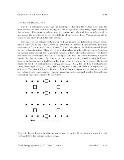
The choice of low voltage configuration will also impact the distribution voltage circuit.<br />
This is illustrated in Fig. 4 for the case of 32 turbines in 4 rows of 8 turbines each. Four unit<br />
transformers T 1 are required in either case. The solid line shows the minimum trench length<br />
for the 1×8 configuration. There will be parallel trenches, with the cable serving as the return<br />
for the loop going through the transformer enclosure without physical connection. The dashed<br />
lineshowsthetrenchlayoutforthe2× 4 configuration, with the arrows indicating a possible<br />
location for the transformer T 2 . The bottom portion of the loop would actually be located<br />
close to the bottom row of turbines, rather than where it is drawn in the figure. The trench<br />
length for the 1 × 8 configuration is 6D dw ,and5D dw +8D cw for the 2 by 4 configuration.<br />
Using the example of D dw =2.5D cw ,the2×4 requires20.5D cw while the 1×8 requires15D cw<br />
of trench. Therefore the 1 × 8 is better in the distribution voltage trench and poorer in the<br />
low voltage trench requirements. It appears necessary to check several possible designs before<br />
concluding that one is superior to the others.<br />
✈ ✈ ✈ ✈ ✈ ✈ ✈ ✈<br />
✈ ✈ ✈ ✈ ✈ ✈ ✈ ✈<br />
✈ ✈ ✈ ✈ ✈ ✈ ✈ ✈<br />
✈ ✈ ✈ ✈ ✈ ✈ ✈ ✈<br />
✛<br />
❄❄<br />
Figure 4: Trench lengths for distribution voltage wiring for 32 turbines in 4 rows, for both<br />
1 × 8and2× 4 low voltage configurations.<br />
Wind Energy Systems by Dr. Gary L. Johnson November 21, 2001


