WIND ENERGY SYSTEMS - Cd3wd
WIND ENERGY SYSTEMS - Cd3wd WIND ENERGY SYSTEMS - Cd3wd
Chapter 6—Asynchronous Generators 6–17 Figure 9: Series resonant circuit for a PM generator. The capacitive reactance X C is selected so the circuit becomes resonant (X C = X s )at rated frequency. The power output will vary with frequency in a way that can be made to match the available power input from a given type of wind turbine rather closely. Overspeed protection will be required but complex pitch changing controls acting between cut-in and rated wind speeds are not essential. The power output of the series resonant PM generator is ke 2 P e = ω2 R a (R s + R a ) 2 +(ωL s − 1/ωC) 2 W/phase (18) Below resonance, the capacitive reactance term is larger than the inductive reactance term. At resonance, ωL s =1/ωC. The power output tends to increase with frequency even above resonance, but will eventually approach a constant value at a sufficiently high frequency. L s can be varied somewhat in the design of the PM generator and C can be changed easily to match the power output curve from a given turbine. No controls are needed, hence reliability and cost should be acceptable. Example A three-phase PM generator has an open circuit line-to- neutral voltage E a of 150 V and a reactance X s of 5.9 Ω/phase at 60 Hz. The series resistance R s may be ignored. The generator is connected into a series resonant circuit like Fig. 9. At 60 Hz, the circuit is resonant and a total three-phase power of 10 kW is flowing to a balanced load with resistances R a Ω/phase. 1. Find C. 2. Find R a . 3. Find the current I a . 4. Find the total three-phase power delivered to the same set of resistors at a frequency of 40 Hz. At resonance, X C = X s =5.9 Ωandω =2πf = 377 rad/s. The capacitance is C = 1 ωX C = 1 377(5.9) = 450 × 10−6 F Wind Energy Systems by Dr. Gary L. Johnson November 21, 2001
Chapter 6—Asynchronous Generators 6–18 The inductance is The power per phase is L s = X s ω = 5.9 377 =15.65 × 10⁻³ H 10, 000 P e = = 3333 W/phase 3 At resonance, the inductive reactance and the capacitive reactance cancel, so V a = E a . The resistance R a is The current I a is given by R a = V 2 a P e = (150)2 3333 =6.75 Ω I a = V a R a = 150 6.75 =22.22 A At 40 Hz, the circuit is no longer resonant. We want to use Eq. 18 to find the power but we need k e first. It can be determined from Eq. 15 and rated conditions as The total power is then k e = E ω = 150 377 =0.398 P tot = 3P e = 3(0.398) 2 [2π(40)] 2 (6.75) (6.75) 2 +[2π(40)(15.65 × 10 −3 ) − 1/(2π(40)(450 × 10 −6 ))] 2 202, 600 = 45.56 + 24.10 = 2910 W If the power followed the ideal cubic curve, at 40 Hz the total power should be ( ) 3 40 P tot,ideal =10, 000 = 2963 W 60 We can see that the resonant circuit causes the actual power to follow the ideal variation rather closely over this frequency range. 4 AC GENERATORS The ac generator that is normally used for supplying synchronous power to the electric utility can also be used in an asynchronous mode[14]. This machine was discussed in the previous Wind Energy Systems by Dr. Gary L. Johnson November 21, 2001
- Page 217 and 218: Chapter 5—Electrical Network 5-27
- Page 219 and 220: Chapter 5—Electrical Network 5-29
- Page 221 and 222: Chapter 5—Electrical Network 5-31
- Page 223 and 224: Chapter 5—Electrical Network 5-33
- Page 225 and 226: Chapter 5—Electrical Network 5-35
- Page 227 and 228: Chapter 5—Electrical Network 5-37
- Page 229 and 230: Chapter 5—Electrical Network 5-39
- Page 231 and 232: Chapter 5—Electrical Network 5-41
- Page 233 and 234: Chapter 5—Electrical Network 5-43
- Page 235 and 236: Chapter 5—Electrical Network 5-45
- Page 237 and 238: Chapter 5—Electrical Network 5-47
- Page 239 and 240: Chapter 5—Electrical Network 5-49
- Page 241 and 242: Chapter 5—Electrical Network 5-51
- Page 243 and 244: Chapter 5—Electrical Network 5-53
- Page 245 and 246: Chapter 5—Electrical Network 5-55
- Page 247 and 248: Chapter 5—Electrical Network 5-57
- Page 249 and 250: Chapter 5—Electrical Network 5-59
- Page 251 and 252: Chapter 5—Electrical Network 5-61
- Page 253 and 254: Chapter 6—Asynchronous Generators
- Page 255 and 256: Chapter 6—Asynchronous Generators
- Page 257 and 258: Chapter 6—Asynchronous Generators
- Page 259 and 260: Chapter 6—Asynchronous Generators
- Page 261 and 262: Chapter 6—Asynchronous Generators
- Page 263 and 264: Chapter 6—Asynchronous Generators
- Page 265 and 266: Chapter 6—Asynchronous Generators
- Page 267: Chapter 6—Asynchronous Generators
- Page 271 and 272: Chapter 6—Asynchronous Generators
- Page 273 and 274: Chapter 6—Asynchronous Generators
- Page 275 and 276: Chapter 6—Asynchronous Generators
- Page 277 and 278: Chapter 6—Asynchronous Generators
- Page 279 and 280: Chapter 6—Asynchronous Generators
- Page 281 and 282: Chapter 6—Asynchronous Generators
- Page 283 and 284: Chapter 6—Asynchronous Generators
- Page 285 and 286: Chapter 6—Asynchronous Generators
- Page 287 and 288: Chapter 6—Asynchronous Generators
- Page 289 and 290: Chapter 6—Asynchronous Generators
- Page 291 and 292: Chapter 6—Asynchronous Generators
- Page 293 and 294: Chapter 6—Asynchronous Generators
- Page 295 and 296: Chapter 6—Asynchronous Generators
- Page 297 and 298: Chapter 7—Asynchronous Loads 7-2
- Page 299 and 300: Chapter 7—Asynchronous Loads 7-4
- Page 301 and 302: Chapter 7—Asynchronous Loads 7-6
- Page 303 and 304: Chapter 7—Asynchronous Loads 7-8
- Page 305 and 306: Chapter 7—Asynchronous Loads 7-10
- Page 307 and 308: Chapter 7—Asynchronous Loads 7-12
- Page 309 and 310: Chapter 7—Asynchronous Loads 7-14
- Page 311 and 312: Chapter 7—Asynchronous Loads 7-16
- Page 313 and 314: Chapter 7—Asynchronous Loads 7-18
- Page 315 and 316: Chapter 7—Asynchronous Loads 7-20
- Page 317 and 318: Chapter 7—Asynchronous Loads 7-22
Chapter 6—Asynchronous Generators 6–17<br />
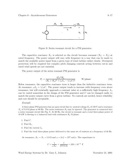
Figure 9: Series resonant circuit for a PM generator.<br />
The capacitive reactance X C is selected so the circuit becomes resonant (X C = X s )at<br />
rated frequency. The power output will vary with frequency in a way that can be made to<br />
match the available power input from a given type of wind turbine rather closely. Overspeed<br />
protection will be required but complex pitch changing controls acting between cut-in and<br />
rated wind speeds are not essential.<br />
The power output of the series resonant PM generator is<br />
ke 2 P e =<br />
ω2 R a<br />
(R s + R a ) 2 +(ωL s − 1/ωC) 2 W/phase (18)<br />
Below resonance, the capacitive reactance term is larger than the inductive reactance term.<br />
At resonance, ωL s =1/ωC. The power output tends to increase with frequency even above<br />
resonance, but will eventually approach a constant value at a sufficiently high frequency. L s<br />
can be varied somewhat in the design of the PM generator and C can be changed easily to<br />
match the power output curve from a given turbine. No controls are needed, hence reliability<br />
and cost should be acceptable.<br />
Example<br />
A three-phase PM generator has an open circuit line-to- neutral voltage E a of 150 V and a reactance<br />
X s of 5.9 Ω/phase at 60 Hz. The series resistance R s may be ignored. The generator is connected into<br />
a series resonant circuit like Fig. 9. At 60 Hz, the circuit is resonant and a total three-phase power of<br />
10 kW is flowing to a balanced load with resistances R a Ω/phase.<br />
1. Find C.<br />
2. Find R a .<br />
3. Find the current I a .<br />
4. Find the total three-phase power delivered to the same set of resistors at a frequency of 40 Hz.<br />
At resonance, X C = X s =5.9 Ωandω =2πf = 377 rad/s. The capacitance is<br />
C = 1<br />
ωX C<br />
=<br />
1<br />
377(5.9) = 450 × 10−6 F<br />
Wind Energy Systems by Dr. Gary L. Johnson November 21, 2001


