J105 Owner Manual 2012.pdf - J/Owners
J105 Owner Manual 2012.pdf - J/Owners
J105 Owner Manual 2012.pdf - J/Owners

Create successful ePaper yourself
Turn your PDF publications into a flip-book with our unique Google optimized e-Paper software.
J/105 <strong>Owner</strong> Guide ...................................................................................................................................................................................................................................................... 2 <br />
J/105 <strong>Owner</strong> <strong>Manual</strong> <br />
HIN:……………………………………. <br />
Yacht Name:…………………………………… <br />
<strong>Owner</strong> Name:…………………………………… <br />
COPYRIGHT © J/BOATS, INC., 2012
J/105 <strong>Owner</strong> Guide ...................................................................................................................................................................................................................................................... 3 <br />
Table of Contents <br />
Introduction ...................................................................................................................................................................... 4 <br />
Specifications .................................................................................................................................................................... 6 <br />
Important Contacts ........................................................................................................................................................ 7 <br />
Getting Started ................................................................................................................................................................. 8 <br />
Commissioning Checklist ......................................................................................................................................... 13 <br />
Tuning The Rig .............................................................................................................................................................. 14 <br />
IMPORTANT Commissioning Follow-‐up ........................................................................................................... 15 <br />
Diagrams, Layouts, & Schematics .............................................................................................................. 16 <br />
Running Rigging & Deck Hardware Layout ........................................................................................... 16 <br />
Mainsheet & Cunningham Diagram .......................................................................................................... 17 <br />
Steering System ................................................................................................................................................. 18 <br />
Fuel & Exhaust System ................................................................................................................................... 19 <br />
Thru-‐Hull & Seacock Locations ................................................................................................................... 20 <br />
<strong>Manual</strong> Fresh Water System ........................................................................................................................ 21 <br />
Head & Holding Tank Schematic ................................................................................................................ 22 <br />
12 V DC Wiring System ................................................................................................................................... 23 <br />
Battery Wiring System .................................................................................................................................... 24 <br />
Lightning/Bonding System ........................................................................................................................... 25 <br />
Engine System ............................................................................................................................................................... 26 <br />
Drive Train ...................................................................................................................................................................... 26 <br />
Fuel System .................................................................................................................................................................... 27 <br />
Cooling System .............................................................................................................................................................. 28 <br />
Exhaust System ............................................................................................................................................................. 28 <br />
General Hints to Avoid Problems ......................................................................................................................... 28 <br />
Engine Safety Precautions ....................................................................................................................................... 29 <br />
Bleeding the Engine .................................................................................................................................................... 30 <br />
Starting Up the Engine ............................................................................................................................................... 30 <br />
Shutting Down the Engine ....................................................................................................................................... 31 <br />
Fueling .............................................................................................................................................................................. 31 <br />
Engine Maintenance ................................................................................................................................................... 32 <br />
Plumbing Systems ....................................................................................................................................................... 33 <br />
<strong>Manual</strong> Fresh Water ................................................................................................................................................... 33 <br />
Thru-‐Hulls & Seacocks .............................................................................................................................................. 33 <br />
Pump Systems ............................................................................................................................................................... 33 <br />
Head System .................................................................................................................................................................. 34 <br />
Electrical System .......................................................................................................................................................... 36 <br />
Safety ................................................................................................................................................................................. 37 <br />
Lightning Protection ................................................................................................................................................... 38 <br />
Galley Stove .................................................................................................................................................................... 39 <br />
Maintenance Tips ........................................................................................................................................................ 39 <br />
Annual Maintenance Checklist ............................................................................................................................... 43 <br />
Storage Tips ................................................................................................................................................................... 44 <br />
APPENDIX A -‐ Best Practices -‐ Boat Inspection .............................................................................................. 46 <br />
APPENDIX B -‐ ABS (Dated) Guidelines for Survey After Construction ................................................ 51 <br />
APPENDIX C -‐ US Watercraft Warranty ............................................................................................................. 52
J/105 <strong>Owner</strong> Guide ...................................................................................................................................................................................................................................................... 4 <br />
Introduction <br />
WELCOME ABOARD and welcome to the J/Boats family of owners. Your boat is designed and <br />
engineered to be the strongest, best performing, easiest-‐to-‐use, and most comfortable sailing <br />
boat of its type. <br />
Sailing involves risk, most of which can be minimized with advance planning and proper <br />
seamanship. The J/105 owner should become proficient in all aspects of handling the vessel <br />
under sail and power, and be well versed with emergency procedures before undertaking any <br />
offshore passage. The owner is further responsible for any required state registration or federal <br />
documentation, accident reporting, outfitting the vessel with proper safety equipment, and the <br />
safe operation of the vessel. Your J/Boats Dealer will be happy to refer you to Boating Safety <br />
Courses or other seminars available. <br />
This owner manual is furnished for your benefit, but shall in no way be construed as any sort of <br />
warranty or contract, express or implied, creating any obligation on the part of J/Boats, Inc., with <br />
respect to any fact or facts or any advice or opinions contained herein. The sole and exclusive <br />
warranty of the product is the US Watercraft Warranty described in the appendix hereto and on <br />
the Warranty Card furnished with the yacht. <br />
J/BOATS, INC. HEREBY DISCLAIMS ANY AND ALL WARRANTIES, EXPRESS OR IMPLIED, <br />
INCLUDING ANY WARRANTY OF FITNESS FOR A PARTICULAR PURPOSE OR ANY IMPLIED <br />
WARRANTY OF MERCHANTABILITY. <br />
Please be sure to complete the warranty card provided with the boat and mail to US Watercraft.
J/105 <strong>Owner</strong> Guide ...................................................................................................................................................................................................................................................... 5 <br />
This manual has been compiled to help you to operate your J/105 with safety and pleasure. It <br />
contains details of the J/105 the equipment supplied or fitted, its systems and information on its <br />
operation. Please read it carefully, and familiarize yourself with the craft before using it. <br />
This owner's manual is not a course on boating safety or seamanship. If this is your first boat, or <br />
you are changing to a type of boat you are not familiar with, for your own comfort and safety, <br />
please ensure that you obtain handling and operating experience before "assuming command" of <br />
the boat. Your dealer or national sailing federation or yacht club will be pleased to advise you of <br />
local sea schools, or competent instructors. <br />
This owner's manual is not a detailed maintenance or trouble shooting guide. In case of difficulty, <br />
refer to the boat dealer, builder or its representative. Always use trained and competent people <br />
for maintenance, fixing or modifications. Modifications that may affect the safety characteristics <br />
of the craft shall be assessed, executed and documented by competent people. The boat builder <br />
cannot be held responsible for modifications he has not approved. <br />
NOTE: Any change in the disposition of the masses aboard may significantly affect the stability, <br />
trim and performance of your boat. Users of this boat are advised that: <br />
• All crew should receive suitable training; <br />
• Bilge water should be kept to a minimum; <br />
• Stability is reduced by any weight added high up; <br />
• In rough weather, hatches, lockers and doorways should be closed to minimize the risk of <br />
flooding; <br />
• Stability may be reduced when towing or lifting heavy weights using a davit or boom; <br />
• Breaking waves are serious stability hazard. <br />
• In some countries a driving license or authorization are required, or specific regulations <br />
are in force. <br />
• Always maintain your boat properly and make allowance for the deterioration that will <br />
occur in time and as a result of heavy use or misuse of the boat. <br />
• Any boat – no matter how strong it may be, can be severely damaged if not used properly. <br />
This is not compatible with safe boating. Always adjust the speed and direction of the <br />
craft to sea conditions. <br />
• If your boat is fitted with a life raft, read carefully its operating manual. The crew should <br />
be familiar with the use of all safety equipment (harness, flares, life raft, etc.) and <br />
emergency maneuvering (man overboard recovery, towing, etc); sailing schools and clubs <br />
regularly organize drill sessions. <br />
PLEASE KEEP THIS MANUAL IN A SECURE PLACE, AND HAND IT OVER TO THE NEW OWNER WHEN YOU <br />
SELL THE CRAFT.
J/105 <strong>Owner</strong> Guide ...................................................................................................................................................................................................................................................... 6 <br />
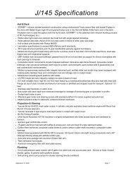
Specifications <br />
MODEL .......................................................................................................................................................... J/105<br />
LOA ................................................................................................................................................ 10.51m (34.50')<br />
LWL ................................................................................................................................................. 8.99m (29.50')<br />
Beam ............................................................................................................................................... 3.35m (11.00')<br />
Draft ................................................................................................................................................... 1.98m (6.50')<br />
Ballast (Lead)........................................................................................................................ 1,542 kg (3,400 lbs.)<br />
Class Minimum Weight (see class rules) ............................................................................... 3,890 kg (8,576 lbs.)<br />
100% Sail Area .................................................................................................................... 53.60 sq m (577 sq ft)<br />
IM ................................................................................................................................................... 12.37m (40.60')<br />
ISP ................................................................................................................................................. 12.83m (42.1’’)<br />
J ...................................................................................................................................................... 4.11m (13.50')<br />
P .................................................................................................................................................... 12.65m (41.50')<br />
E ...................................................................................................................................................... 4.45m (14.60')<br />
Engine ................................................................................................................... Yanmar 3YM20, 15.3kw (21hp)<br />
Fuel Capacity* ............................................................................................................... 45.4 liters (12 US gallons)<br />
Engine Alternator ............................................................................... 60 amp standard Yanmar marine alternator<br />
House Battery Capacity ................................................................................... 90 amp hours, add’l 90 amp option<br />
Standard Propeller ..................................................................................... Martec folding prop 15” dia. x 14” pitch<br />
Battery Type ......................................................................................................................................... Deep-cycle<br />
Holding Tank Capacity ................................................................................................................. 45 liters (12 gal.)<br />
Water Capacity** ......................................................................................... 18.9 liter (5 US gallon) Portable Tank<br />
Hull & Deck Core Material ...................................................................................................... Baltek® SB50 Balsa<br />
Hull & Deck Molding Process ............................................................................................................. Hand Lay-up<br />
Hull Blister Warranty ................................................................................................. 10 Year: <strong>Owner</strong> Transferable<br />
Mast Height Above Water .................................................... 15.34 m (50’ 4”) not including masthead instruments<br />
* Fuel capacity may not be completely usable depending upon trim and loading of the craft and a <br />
20% reserve should be kept on board. <br />
** All water capacity may not be usable depending upon trim and loading of the craft.
J/105 <strong>Owner</strong> Guide ...................................................................................................................................................................................................................................................... 7 <br />
Important Contacts <br />
Dealer: .................................................................................... Phone: ................................................................................ <br />
Street: ...................................................................................... Web Site: ........................................................................... <br />
City, State, Zip: ..................................................................... E mail: ................................................................................. <br />
Marketing & Design J/Boats, Inc. 401-‐846-‐8410 <br />
PO Box 90 <br />
info@jboats.com <br />
Newport, RI 02840 <br />
Builder: US Watercraft 401-‐682-‐1661 <br />
225 Alexander Rd. info@waterlinesystems.com <br />
Portsmouth, RI 02871 <br />
Cushions: Ken’s Upholstery 401-‐246-‐1244 <br />
101 Narragansett Ave. <br />
Barrington, RI 02806 <br />
Canvas: Thurston Sails 401-‐254-‐0970 <br />
Tupelo Street <br />
thurstoncanvas@fullchannel.net <br />
Bristol, RI 02809 <br />
Spars: Charleston Spar, Inc. 704-‐597-‐1502 <br />
3901 Pine Grove Circle sales@sparcraft-‐us.com <br />
Charlotte, NC 28206 <br />
Hydraulics: Sailtec, Inc. 920-‐233-‐4242 <br />
2930 Conger Court info@sailtec.com <br />
Oshkosh, WI 54904 <br />
Deck Hardware: Harken 262-‐691-‐3320 <br />
1251 E. Wisconsin Ave. harken@harken.com <br />
Pewaukee, WI 53072 <br />
Deck Hardware: Spinlock USA 877-‐465-‐6251 <br />
PO Box 2672 <br />
www.SpinlockUSA.com <br />
Newport, RI 02840
J/105 <strong>Owner</strong> Guide ...................................................................................................................................................................................................................................................... 8 <br />
Getting Started With Your J/105 <br />
Generally, your dealer or commissioning yard will help you prepare your boat before launching. <br />
And in most instances they will undertake the entire commissioning job. They are experts in the <br />
field and are capable of completing most commissioning tasks. <br />
Before Proceeding <br />
Before you begin to assemble your new boat you should become familiar with the different sail <br />
control systems and associated hardware. All running rigging and loose deck hardware items are <br />
shipped from the factory in parts boxes complete with part inventory sheets. To help you <br />
properly install these items please refer to the rigging and hardware sections and diagrams in <br />
this guide. <br />
Commissioning Checklist -‐ will help you double check that the J/105 is assembled properly and all <br />
systems and rigging are functioning properly. If a boatyard other than an authorized J/Boat <br />
dealer is performing the work, review this list with them to establish what needs to be done and <br />
by whom. <br />
Topsides -‐ wash off all dirt and grime accumulated from delivery. Use only non-‐abrasive <br />
cleansers on the gelcoat. Then apply a coat of high quality car or boat wax to prolong the life and <br />
sheen of the gelcoat. <br />
Bottom -‐ Bottom preparation is critical to long-‐lasting enjoyment. To ensure a professional <br />
finish, carefully review the paint manufacturer’s recommendations for preparing the bottom. Be <br />
sure that there is a healthy amount of epoxy primer (using paint manufacturer build-‐up <br />
recommendations) to cover the keel PRIOR to final coating of bottom paint. <br />
Chainplates -‐ are custom manufactured of polished stainless steel. Shroud chainplates are <br />
mounted directly to the main bulkhead. The backstay chainplate is bolted to a reinforced area of <br />
the transom. <br />
Toe Rails -‐ toerails are included at the deck edge forward of the mast and in the cockpit for the <br />
helmsman aft of the wheel. <br />
Stanchions & Pulpits -‐ are designed for proper offshore safety as well as to facilitate access to the <br />
boat. Optional are lifeline gates to port and starboard. The (3) standard stern lifelines are <br />
equipped with quick release Pelican hook fittings. All stanchions are 1” diameter stainless steel <br />
and are secured into their bases with machine set screws. <br />
Lifelines -‐ The upper and lower lifelines are 5/32" 1x19 wire in accordance with ORC safety <br />
regulations. They run the length of the boat and are fastened at either end by stainless forks and <br />
turnbuckles. Each lifeline is clearly marked for easy installation. The installation is as follows: <br />
• Insert all stanchions into the sockets provided along the edge of the deck. Secure each <br />
stanchion in place by tightening the two screws in each base. We recommend that you <br />
dip the screws in blue Loctite or sealant before securing, so they don’t work themselves <br />
loose over time.
J/105 <strong>Owner</strong> Guide ...................................................................................................................................................................................................................................................... 9 <br />
• Install all lifelines without tightening the turnbuckles. Remove the eyes at the ends of the <br />
lifelines and thread them through the stanchions. If the boat is equipped with the <br />
optional lifeline pads, thread the lifeline through these prior to attaching to the stern rail. <br />
• Finish off the job by tightening the turnbuckles, and taping off the turnbuckle “split rings” <br />
(or cotter pins) for a secured finished appearance. <br />
Skylight Ventilation Hatches -‐ are made of extruded anodized aluminum and scratch-‐resistant <br />
acrylic cover. The hatch comes equipped with a ventilation position and 180 degree articulation. <br />
Fixed Ports & Optional Opening Ports -‐ are made with extruded aluminum frames and smoke <br />
colored acrylic. The optional opening ports can maximize interior comfort and cross-‐flow <br />
ventilation. There are four fixed standard ports and two optional opening ports to replace the aft <br />
fixed aluminum ports. <br />
DO NOT PERMIT ACETONE OR OTHER HARSH CLEANSERS TO GET ON PORTS OR HATCHES AS THEY <br />
MAY DAMAGE THE FINISH & CLARITY OF SOME DECK HARDWARE. <br />
Deckhouse Handrails -‐ Stainless handrails are standard for secure maneuvering on deck and ease <br />
of maintenance. <br />
Winches -‐ Standard winches are aluminum self-‐tailing models from Harken. The location of these <br />
winches facilitates sailing with one or two aboard. Each is geared to match the load requirements <br />
of the specific task. <br />
Standard Steering System <br />
The steering system is carefully engineered to provide finger-‐tip control. This is achieved by <br />
utilizing high quality Jefa rudder bearings. The rudder itself is made of unidirectional glass, with <br />
two molded halves bonded together, and a highly reinforced fiberglass shaft. It's engineered to <br />
withstand tremendous shear loads for storm conditions. <br />
Standard Tiller -‐ is a molded, composite part bolted to a custom stainless steel tiller head mounted <br />
to the top of the rudder shaft. The Spinlock adjustable hiking stick is attached on the forward <br />
end of the tiller to enable the helmsman improved visibility sitting further outboard. <br />
Optional Wheel Steering System <br />
Pedestal & Wheel -‐ is custom molded fiberglass. Inside the "compass cowl" is a standard Lewmar <br />
sprocket that is connected to a chain and 7x19 wire to the custom aluminum quadrant. <br />
Adjustment to this linkage is achieved by a set of turnbuckles connected to the steering wire. <br />
These can be accessed through the lazarette locker to starboard of the rudder post. Wheel is a <br />
Lewmar wheel with an elkhide cover. <br />
Rudder Stock Seal -‐ is located at the top of the lower rudder bearing. It is a simple flexible boot <br />
type design that prevents water from entering the hull. If tiller steering is installed, the fiberglass <br />
rudder tube is continuous between the hull and the deck.
J/105 <strong>Owner</strong> Guide ...................................................................................................................................................................................................................................................... 10 <br />
Emergency Tiller -‐ is installed by removing the access plate, and placing the base of the tiller over <br />
the head of the rudder stock. Fit the emergency tiller NOW to see how the system works BEFORE <br />
you get caught in a situation where you may not have time! <br />
Before Launching -‐ check the system of cables, quadrant, and sheaves to ensure they are working <br />
smoothly. If the steering seems loose, tighten the turnbuckles by hand and re-‐pin them. Beware <br />
that you do not over-‐tighten the cables. Please note that your steering should be checked <br />
periodically for "tightness" and for presence of properly bent cotter-‐pins. <br />
Rigging Systems <br />
The running and standing rigging items supplied with your boat are designed for efficiency. A <br />
wealth of racing and cruising experience has gone into the deck layout to make sailing and boat <br />
handling safe and easy to handle by a couple or a racing crew. <br />
The most unique system on your J/105 is the bow sprit system for the asymmetric spinnaker. <br />
We believe this system is a major improvement over conventional systems, so let's start by <br />
explaining how it works! <br />
Carbon Fiber Bow Sprit -‐ The carbon fiber bow sprit is custom made and is designed to withstand <br />
the loads associated with the class asymmetric spinnaker without any additional support. The <br />
pole consists of a carbon tube faired smooth and finished with a clear Awlgrip high gloss paint, <br />
and two end fittings. The forward end fitting has a "U" bolt which serves as the attachment point <br />
for the tackline/snuffer block. The aft end fitting houses all hardware necessary for the adjuster <br />
line and shock cord retrieval system. <br />
Bow Sprit Launching Line -‐ The control line to pull out the bow sprit is designed to be adjusted <br />
without leaving the cockpit. The line is dead-‐ended to the outboard pad eye on the forward most <br />
bulkhead in the forepeak. The line then leads through the thru-‐pole blocks on the aft end fitting <br />
of the carbon fiber pole (be sure the "U" bolt on the other end of the pole is up), forward through <br />
a block on the inboard padeye on the forepeak bulkhead, then under deck through the bullseye <br />
fairleads, the main bulkhead, and finally to the cam cleat mounted on the aft side of the cabin top <br />
to starboard <br />
Asymmetric Shock Cord Retrieval System -‐ The shock cord system allows the pole to automatically <br />
retract when you uncleat the control line. Set up as follows: attach one end of shock cord to the <br />
pole end fitting pad eye, lead through the Harken double block mounted on padeye on the <br />
hanging locker bulkhead, then lead cord through the bullseye on the bottom of the pole end <br />
fitting to the forward single Harken block, back through the bullseye, around the becket of the aft <br />
block, and secured to the back end of the pole. You may need to experiment once or twice to get <br />
the appropriate tension on the shock cord. It should be relatively easy to extend the pole fully, <br />
and when released, should quickly retract into the boat. If you do not already have a preventer <br />
line, put a knot in the cockpit control line behind the cam cleat (in the cockpit) to prevent the <br />
sprit from banging into the bulkhead when released. <br />
Harken Headsail Furling -‐ The Harken Unit 1 furler is provided with the boat standard and <br />
requires assembly prior to installing the mast. A complete instruction manual is included with <br />
this hardware detailing the proper procedure. The pin-‐to-‐pin headstay length necessary to <br />
complete this task for the J/105 is 12929mm or 42’ 5”. The provided pre-‐feeder should be lashed <br />
and taped halfway between the feeder gate and the lower extrusion leg.
J/105 <strong>Owner</strong> Guide ...................................................................................................................................................................................................................................................... 11 <br />
Mast -‐ Rigging the J/105 mast is a common procedure, and best handled by a qualified marine <br />
rigger. All spreaders, shrouds, and halyards are installed and properly taped and secured. Be sure <br />
all mast related electronics and wind indicators are properly wired and installed prior to <br />
stepping the mast. After stepping the mast it is VERY IMPORTANT to properly brace the mast <br />
within the mast collar PRIOR to sailing with the provided Pre-‐Molded Spartite mast wedge. We <br />
also recommend that a small cord is tied and taped approx. 24” above the lower spreader <br />
between the intermediate shroud and upper shroud if you plan to sail with any type of spinnaker. <br />
Simply tie this line to each shroud (allowing for some slack) and tape ends over with rigging tape. <br />
This prevents the spinnaker (during a take-‐down) from potentially dropping into the V that is <br />
formed at the lower spreader between these shrouds. <br />
Hydraulic Backstay -‐ The J/105 is equipped with an integral hydraulic backstay to help you fine <br />
tune your rig and sails for optimum performance. This hydraulic unit is simple to operate, easy <br />
to maintain, and highly reliable. The cylinder is affixed to the backstay tang on the transom and <br />
to the backstay. In order to attach the backstay, you must pull out the SS shaft and fully extend it. <br />
Boom -‐ Run the reef lines so the red line (port) is led through the port sheaves and the green line <br />
(starboard) is led through the starboard sheaves at both the outboard end and the gooseneck. <br />
The starboard reef doubles as the cunningham. <br />
Boom Vang -‐ The standard boom vang is a mechanically operated spring loaded boom vang with a <br />
block and tackle purchase system. This vang system allows for quick and easy adjustment and <br />
also acts as a boom topping lift. The vang is affixed to the vang plate welded underneath the <br />
boom and to the mast at the vang gooseneck located just above the mast collar. See the vang <br />
operating instructions for how to adjust the internal spring for best results. <br />
Sail Control Systems <br />
After stepping the mast and connecting the boom, vang, roller-‐furler, and integral backstay, rig all <br />
halyards and the remaining sail control systems on deck. <br />
Main Halyard -‐ exits the mast on the port side, runs through a turning block at the mast collar, <br />
through the inboard port organizer block and then aft through the port double stopper (inboard <br />
hole) and finally to the halyard winch. The tail end is stored in the supplied line bag to be <br />
mounted outboard and forward of the stopper. <br />
Jib Halyard -‐ exits the mast to port, leads through the forward mast base block, aft to the outboard <br />
sheave on the organizer block, through the outboard stopper hole, and store tail in line bag. <br />
Spinnaker Halyard -‐ exits the mast to starboard and leads to the outboard sheave and stopper. <br />
Mainsheet Traveler -‐ is a Harken low friction system. The 3:1 purchase system on each side <br />
controls a Harken Windward Sheeting Car mounted on midrange track (see diagram). <br />
Outhaul -‐ is adjusted at the cleat on the underside of the boom and comes pre-‐assembled. <br />
Cunningham -‐ The cunningham doubles as the starboard reef line. To set it up as a cunningham <br />
simply tie a knot at the boom end tail of the reef line. The line leads forward to the sheave at the <br />
gooseneck, up to the cunningham block/hook back down through a bullseye on the mast, down <br />
to the mast base block and aft to the inboard stopper.(see diagram). To use the continuous reef
J/105 <strong>Owner</strong> Guide ...................................................................................................................................................................................................................................................... 12 <br />
system simply run the boom end tail through the clew reef grommet, back down around the <br />
boom and tie a bowline. <br />
Mainsheet -‐ is a 24:1 system with a 6:1/4:1 set-‐up (see diagram). The system is designed to allow <br />
easy adjustments of the mainsheet. The location of the traveler also facilitates single-‐handed <br />
sailing and adjustments. The fixed centerline cleat base rotates to port and starboard for a <br />
proper lead. Be sure to put a "stopper knot" like a figure-‐eight at the end of the mainsheet. <br />
Jib Sheet -‐ is continuous and attaches to the roller-‐furler headsail by a simple knot, leads to the jib <br />
block on the track, aft to the lower sheave of the double turning block on the rail and finally to <br />
the primary winch. <br />
Spinnaker Sheets -‐ lead from the clew of the spinnaker aft outside the lifelines through the <br />
spinnaker sheet blocks (shipped loose) turning forward to the upper sheave of the double <br />
fairlead blocks along the rail and then to the primary cockpit winches or secondary cabin-‐top <br />
winches.
J/105 <strong>Owner</strong> Guide ...................................................................................................................................................................................................................................................... 13 <br />
Commissioning Checklist <br />
Pre-Launch<br />
___ Read equipment owner manuals<br />
___ Pre-rig mast and check installation of:<br />
• halyards<br />
• blocks<br />
• electronics<br />
• shrouds<br />
• spreader end chafe guards<br />
• shroud spinnaker protection<br />
• lifeline pins<br />
• Mast Boot<br />
___ Pre-rig boom<br />
___ Bottom painted or touched up<br />
___ Check propeller/strut/zinc<br />
___ De-winterize engine and check status of:<br />
• engine oil/ filter<br />
• coolant level<br />
• transmission fluid level<br />
• water intakes/filter<br />
• fuel lines/filter<br />
___ Check battery charge<br />
___ Check all hose clamps, tighten as required<br />
___ Close all seacocks<br />
___ Wire tie wooden plugs near all thru-hulls<br />
Steering System (Wheel)<br />
___ Attach Wheel<br />
___ Check steering cable tension<br />
___ Test fit emergency tiller<br />
___ Check rudder stops<br />
Launch<br />
___ Check for leaks<br />
___ Check seacocks<br />
___ Check stuffing box<br />
Engine Start<br />
___ Read engine owner’s manual<br />
___ Open raw water intake seacock<br />
___ Check fuel<br />
___ Start engine<br />
___ Check exhaust for cooling water flow<br />
___ Check oil press., water temp., charging gauges<br />
___ Check transmission- forward/reverse<br />
___ Check stuffing box<br />
Step Mast<br />
___ Locate mast step in middle of range and tighten bolts.<br />
___ Hoist spar and lower into boat<br />
___ Attach headstay to stemhead fitting<br />
___ Attach backstay and cylinder to backstay plate<br />
___ Attach all shrouds and hand tighten<br />
___ Install mast wedges and boot<br />
___ Connect mast junction box wires<br />
Rigging<br />
___ Install boom<br />
___ Lead all halyards to stoppers on cabin top<br />
___ Rig reef lines<br />
___ Install and connect boom vang<br />
___ Dock tune spar per tuning guide<br />
___ Rig bow sprit launching guide<br />
Loose Gear<br />
___ Fenders and lines<br />
___ Dock lines<br />
___ Winch handles<br />
___ Ignition/boat keys<br />
___ Bilge pump handle<br />
___ Mast wedges ready<br />
___ Double-check sling locations and mark<br />
___ Anchor, chain and rode<br />
___ Fire extinguishers installed<br />
___ First aid kit<br />
___ Coast Guard Required Safety Gear<br />
Systems Check<br />
___ Fill fuel tank<br />
___ Check operation of electrical systems and pumps<br />
___ Check sailing electronics<br />
Trial Sail<br />
___ Raise and lower sails to check for fit<br />
___ Monitor engine performance and check stuffing box<br />
___ Check bilge for leaks<br />
___ Check sailing electronics<br />
___ Check reef points and lines<br />
___ Check for steering cable stretch (wheel only)
J/105 <strong>Owner</strong> Guide ...................................................................................................................................................................................................................................................... 14 <br />
Tuning the J/105 Rig <br />
Following is a general guide to tuning your J/105 mast. Please consult your sailmaker for “fine-tuning”<br />
the mast to match the sails. <br />
With the standard length J/105 headstay and the mast step situated in the middle, the mast rake <br />
(as measured from the back of the mast at deck level to a plumb on the main halyard) should be <br />
approximately 30 inches. Several owners have opted to install an additional toggle at the top of <br />
the headstay, and then shorten the drum turnbuckle so to lower the drum as close as possible to <br />
the deck. According to J/105 Class Rule 7.4 “the headstay system length, measured between the <br />
centerline of the headstay pin on the mast to the intersection of the stem line and the sheer line <br />
at the bow, shall not be greater than 13035mm nor less than 12985mm. We recommend the <br />
maximum allowed headstay length for most conditions. <br />
The upper shrouds are attached to the outer chainplate hole. The lowers are connected to the <br />
inner hole. The intermediates are secured in the forward hole. Begin by hand tightening the <br />
shrouds, being careful to keep the mast centered aloft. Check alignment by hoisting a tape <br />
measure up the main halyard and comparing measurements to the port and starboard <br />
chainplates. When the top of the mast is centered, sight up the mast track to check for alignment <br />
of the lower part of the mast. Hand adjust the shrouds as necessary to center the mast. <br />
After the rig is centered and hand tight, we recommend additionally tightening the shrouds the <br />
following number of turns: <br />
Upper Shrouds: +11 turns <br />
Lower Shrouds: + 2 turns <br />
Intermediates: <br />
+ 8 turns <br />
You’ll find it easiest to tighten the upper shrouds if you pump the backstay down 2-‐3 inches first <br />
to relieve load. Under sail, it is easiest to adjust only the leeward shrouds, then tack to adjust the <br />
other side. <br />
Once you have initially tuned your J/105, then go sailing in a brisk breeze, spending equal time <br />
on both tacks. Even though rod rigging is the lowest stretch material possible, you’ll still see a <br />
little loosening after the initial breaking in period. Be sure to sight up the mast while it is under <br />
load to see if it remains in column.
J/105 <strong>Owner</strong> Guide ...................................................................................................................................................................................................................................................... 15 <br />
Important Commissioning Follow-‐up <br />
The initial sea trial period, or the first 30 days after launching a new boat always requires <br />
important follow-‐up by the owner including sail fit checks, rig tuning and adjustments, <br />
instrument and compass calibration, maintenance and systems checks, etc... Your dealer and <br />
their support staff and other local suppliers will help you with this process. It is imperative that <br />
the following areas of the boat are inspected and confirmed to be operating properly after the <br />
initial 30 days. <br />
30 Day Inspection List <br />
PROPELLER SHAFT ZINC -‐ Inspection of the shaft zinc is very important in the first 30 days <br />
following launch. Accelerated zinc corrosion may indicate an electrical wiring problem onboard <br />
or stray current from a nearby boat. RAPID CORROSION OF THE SHAFT ZINC SHOULD NEVER <br />
BE IGNORED. IMMEDIATE ATTENTION IS REQUIRED BY THE OWNER & DEALER. Failure to <br />
respond to this important sign of galvanic corrosion may lead to severe damage to underwater <br />
metals. <br />
STEERING CABLES ON WHEEL-‐SUPPLIED BOATS – Steering cables are known to stretch after <br />
initial setting and usage. The following technique is helpful for adjusting cable tension in the <br />
system. A top quality roller chain to wire steering system can be kept in “as new” sensitivity by <br />
keeping the wire at a correct tension. To check for proper wire tension, lock the wheel in position <br />
by using the pedestal brake, or by tying off the wheel. Cable tension is best when you cannot <br />
move the quadrant or drive wheel by hand with the wheel locked in place. Over tightening will <br />
greatly reduce the sensitivity of the system. When leaving your boat at her mooring or slip, make <br />
sure that your wheel is properly tied off. DO NOT LEAVE THE STEERING SYSTEM TO FREE <br />
WHEEL. <br />
MAST, SPARS, RIG & RIGGING – The standing rigging terminations will seat and the SS rod will <br />
stretch during initial sea trials. It is prudent to inspect all fittings, terminations, turnbuckles, <br />
halyards, and mast wedges, and to look for any signs of unusual wear after sea trials. Checking <br />
and adjusting rig tuning is also recommended. <br />
The following ship systems must also be tested for proper operation: <br />
• ENGINE, THROTTLE CONTROL & FUEL SYSTEM. <br />
• FRESH WATER SYSTEM. <br />
• HEAD SYSTEM. <br />
• MANUAL AND ELECTRIC BILGE PUMP SYSTEMS. <br />
Finally: <br />
• REVIEW PROPER SAFETY EQUIPMENT – confirm all required safety gear is onboard and <br />
in working order. <br />
• CHECK ALL LIFELINE TERMINATIONS & TURNBUCKLES – Confirm cotter pins in <br />
turnbuckles and set screws are secure in all stanchion bases. <br />
• RE-‐VISIT & REVIEW COMMISSIONING CHECKLIST <br />
ANY PROBLEM AREAS IDENTIFIED ABOVE MUST BE ADDRESSED PROMPTLY.
J/105 <strong>Owner</strong> Guide ...................................................................................................................................................................................................................................................... 16 <br />
Diagrams, Layouts, & Schematics <br />
Running Rigging & Deck Hardware Layout
J/105 <strong>Owner</strong> Guide ...................................................................................................................................................................................................................................................... 17 <br />
Mainsheet & Cunningham Diagram
J/105 <strong>Owner</strong> Guide ...................................................................................................................................................................................................................................................... 18 <br />
Steering System
J/105 <strong>Owner</strong> Guide ...................................................................................................................................................................................................................................................... 19 <br />
Fuel & Exhaust System
J/105 <strong>Owner</strong> Guide ...................................................................................................................................................................................................................................................... 20 <br />
Thru-‐Hull & Seacock Locations
J/105 <strong>Owner</strong> Guide ...................................................................................................................................................................................................................................................... 21 <br />
<strong>Manual</strong> Fresh Water System
J/105 <strong>Owner</strong> Guide ...................................................................................................................................................................................................................................................... 22 <br />
Head & Holding Tank Schematic
J/105 <strong>Owner</strong> Guide ...................................................................................................................................................................................................................................................... 23 <br />
12V DC Layout
J/105 <strong>Owner</strong> Guide ...................................................................................................................................................................................................................................................... 24 <br />
Battery Wiring System
J/105 <strong>Owner</strong> Guide ...................................................................................................................................................................................................................................................... 25 <br />
Lightning/Bonding System
J/105 <strong>Owner</strong> Guide ...................................................................................................................................................................................................................................................... 26 <br />
Engine System <br />
The engine and fuel system is engineered to be conveniently accessible for repairs and general <br />
maintenance. Located behind the companionway ladder, there is access on the aft sides (through <br />
the cockpit lockers) and in front of the engine from which important functions can be reached; <br />
including water strainer, fuel injectors, fuel filter, fuel primer, expansion chamber, and <br />
alternator. <br />
Before starting the engine read the engine manufacturer's owner's manual for proper break-‐in <br />
and operating procedures. Once the engine is running, inspect it for any discrepancies, like oil <br />
leaking, excessive water leaks, or anything out of the ordinary. <br />
Drive Train <br />
• Engine Control Panel -‐ is mounted in the cockpit. It contains the starter, stop button, <br />
warning lights, and gauges. The combination throttle/gearshift is mounted on the <br />
cockpit wall. Double-‐check all mechanical connections between engine and on-‐deck <br />
equipment. <br />
• Engine Bed -‐ is constructed of highly reinforced fiberglass. This provides a superior <br />
mount over wood and is also rot-‐proof. The engine sits on heavy duty rubber shock <br />
mounts to help isolate the engine vibration from the boat. Check to see that the engine is <br />
sitting correctly on them and the bolts tightly secured. <br />
• Neutral Safety Switch -‐ the J/105 is equipped with a neutral safety switch and the engine <br />
will not start without the throttle control in a proper neutral or advanced neutral <br />
position. <br />
This is the complete system that propels your boat. It includes the following components: <br />
coupling, stuffing box, shaft log, shaft, strut, and the propeller. <br />
• Transmission -‐ is attached to the aft end of the engine and houses the reduction and <br />
reverse gears. These gears generally need little maintenance, but the oil level should be <br />
checked periodically. <br />
• Stuffing Box -‐ is aft of the engine where the propeller shaft passes through the hull. It is a <br />
waterproof housing consisting of a rubber "jacket" attached to the tube and a brass <br />
bearing with hose clamps. When the engine is running, check to see that intermittent <br />
drips of water appear where the shaft enters the stuffing box. If the drips are a <br />
continuous stream, i.e. more than one every ten seconds, you must tighten the <br />
compression nut on the forward end of the stuffing box. This requires two large pipe <br />
wrenches to tighten the forward nut over the aft "core nut." It should not get hot when <br />
running. <br />
• Propeller -‐ is a MARTEC folding prop of high quality bronze alloy. Check to see that the <br />
blades on the prop open almost perpendicular to the shaft. The prop is simple to care for <br />
and can withstand years of hard use. However, there are a few easy precautions which <br />
can prolong its life:
J/105 <strong>Owner</strong> Guide ...................................................................................................................................................................................................................................................... 27 <br />
o<br />
o<br />
o<br />
o<br />
Coat it with an excellent silicone grease film. <br />
Check to see that the joints in the folding prop have a good coating of waterproof <br />
grease. <br />
Check that all cotter pins are bent over properly. <br />
Check that the blades are smooth. <br />
• Prop Shaft -‐ is stainless and is supported at the inboard end by the shaft coupling and at <br />
the outboard end by the strut containing a rubber "cutlass bearing." Before launching <br />
attach a "shaft zinc" to minimize corrosion. The zinc should be replaced every time the <br />
boat is hauled. Check the "cutlass bearing" periodically for wear and tear. If it is loose, <br />
replace it. <br />
• Engine/Shaft alignment is set by the builder to ensure that the engine, shaft, stuffing box, <br />
and prop are properly adjusted to minimize engine vibration. If there seems to be <br />
excessive vibration, notify your dealer and have them investigate. <br />
Fuel System <br />
The Fuel System is located centrally in the boat for effective weight distribution. It consists of the <br />
fuel tank, fill hoses and caps; fuel lines and filters and the vent. Use only Diesel fuel in the system. <br />
• Fuel Tank & Line -‐ run from underneath the port main cabin settee, under the cabin sole <br />
and up to the fuel primer pump. From there, fuel flows into the injectors. The tank is <br />
aluminum, baffled to prevent fuel slosh, and vented overboad. For a layout, please see <br />
the Fuel System diagram. <br />
• Fuel Level Gauge -‐ is located on top of the tank. The gauge reflects level (height) of fuel in <br />
the tank, not the quantity. Try to maintain a minimum level of 1/2 tank filled at all times. <br />
• WARNING-‐ IF YOU ARE MOTORING AND HAVE LESS THAN 1/3 TANK OF FUEL, BE <br />
CAREFUL OF HEELING THE BOAT TO PORT, OR YOU WILL RISK AIR GETTING INTO THE <br />
FUEL LINE. Familiarize yourself with the bleeding procedure instructions provided with <br />
the Yanmar paperwork. <br />
• Fuel Line Shut-‐Off Valve -‐ sits atop the tank at its aft end. Since diesel engines require <br />
bleeding after they have been deprived of fuel, it's important that the shut-‐off valve be in <br />
the "ON" position (lever parallel to piping) anytime the engine is started. <br />
• Fuel Tank Access Plate -‐ is atop the fuel tank and provides access inside to clean the tank <br />
or check the fuel gauge.
J/105 <strong>Owner</strong> Guide ...................................................................................................................................................................................................................................................... 28 <br />
Cooling System <br />
The J/105’s engine utilizes both a “closed” cooling system, in which a mixture of fresh water and <br />
antifreeze is circulated within the engine, and a “raw water” system, in which a heat exchanger <br />
supplies a constant flow of outside water, pumped in through the raw-‐water intake, to cool the <br />
coolant mixture. <br />
• Coolant system -‐ The filler cap (it looks like a radiator cap) for the freshwater-‐and-antifreeze<br />
cooling system is located on top of the engine manifold. Check the coolant level <br />
of the manifold and the coolant sub-‐tank aft of the engine, (check when the engine is <br />
cool). When adding coolant, follow the engine manufacturer’s recommendations for the <br />
proper fresh water/antifreeze ratio. In climates where freezing may occur in winter, test <br />
the coolant mixture for freezing point. Add coolant as needed if the system is not drained <br />
for winter storage. <br />
• Raw-‐water system -‐ Located in the engine compartment, the J/105’s raw-‐water strainer <br />
helps prevent clogging of the raw-‐water cooling system and overheating of the engine. <br />
Check the strainer basket often to insure that the flow of cooling water is unimpeded. To <br />
clean: Ensure the engine water intake thru-‐hull is closed. Check that the lever is <br />
perpendicular to the intake. Unscrew the top of the strainer and remove the basket from <br />
inside the plastic case. Wash thoroughly with water or replace with a new one if badly <br />
soiled. Reinstall the basket and be sure it is seated properly in the bowl. Then reinstall <br />
the lid tightly. <br />
Exhaust System <br />
The J/105 is equipped with a water-‐injected water-‐lift exhaust system that dissipates exhaust <br />
heat and acts as the exhaust muffler. If the flow of cooling water is interrupted and the engine <br />
overheats severely, the rubber hose coming from the engine exhaust elbow may melt. Always <br />
check this hose after an occurrence of overheating. <br />
Cooling water can accumulate in the bottom of the water-‐lock muffler; when de-‐commissioning <br />
your boat for the season, the muffler either should be drained by unscrewing the drain plug on <br />
the bottom of the muffler or antifreeze should be added so that residual water doesn’t freeze. <br />
If the engine does not start after a prolonged period of cranking over (starting), be sure to drain <br />
the pot or exhaust loop. Water accumulates here and may fill enough to flow back into engine <br />
manifold if engine does not start. <br />
General Hints To Avoid Problems <br />
• Monitor brightness of cabin lighting and charge battery as required by running engine. <br />
Batteries are charged when running the engine. <br />
• Stop engine with the start/stop switch. <br />
• NEVER turn battery switch to OFF position while engine is running as this could damage <br />
the alternator. <br />
• For best performance and fuel economy a cruising R.P.M. of 2,200 -‐ 2,800 works well. <br />
Please refer to the Yanmar manual for recommendations. It is good practice to vary RPM
J/105 <strong>Owner</strong> Guide ...................................................................................................................................................................................................................................................... 29 <br />
levels periodically when cruising under power for a long distance. Be sure to thoroughly <br />
read and follow the manufacturer’s manual for proper break-‐in procedure for the <br />
standard Yanmar Diesel engine. <br />
• Do not run engine at full throttle for sustained periods, as breakdowns may occur. Most <br />
importantly, find an RPM that runs smoothly and follow the Yanmar guide. Avoid <br />
"vibrating" RPM speeds when possible. <br />
• Keep engine gear shift lever in "REVERSE" position while sailing to prevent possible <br />
"free-‐wheeling" of prop <br />
• CAUTION: The J/105 engine is very quiet, and it is possible to forget that it is running. <br />
Before shifting the gear shift lever to lock the shaft for sailing, double check that the <br />
engine is turned off. <br />
Engine Safety Precautions <br />
Due to high temperatures it is recommended that after running the diesel for more than two <br />
hours you reduce speed to idle and allow excess heat to dissipate for five to ten minutes prior to <br />
shutting the motor off. <br />
The most common cause of trouble is contaminated or dirty fuel. Your boat is equipped with a <br />
primary fuel filter located in the engine compartment and a secondary filter on the engine. The <br />
wise skipper carries replacement filter cartridges. Familiarize yourself with the bleeding <br />
procedure for the engine and you should learn how to bleed it yourself. The procedure only <br />
takes a few minutes after you are acquainted with it, but can be exasperating to the uninitiated.
J/105 <strong>Owner</strong> Guide ...................................................................................................................................................................................................................................................... 30 <br />
Bleeding The Engine <br />
Reprinted from Mac Boring Service Bulletin: <br />
This bulletin contains helpful information for bleeding the fuel system of a Yanmar Diesel and <br />
other small diesels as well. Please post where your field service personnel can review. <br />
Since the presence of air in the fuel system anywhere between the fuel tank and the injector <br />
will lead to a no start or erratic running condition, always bleed the air from the system when <br />
the fuel system is disassembled, filter changed or if run out of fuel. <br />
1. Make sure fuel tank off is in "on" position. <br />
2. Bleed the air from fuel filter. Loosen the air bleed screw at the top of the fuel filter body <br />
and operate the manual handle the lift pump until the air bubbles completely expel in the <br />
fuel flowing from the filter. <br />
3. Bleed the air from the fuel return pipe. Loosen the connector bolt of the fuel return pipe <br />
installed on the fuel injector, and bleed the air by operating the manual handle of the lift <br />
pump. (If there is more than one injector, bleed the one at the end of the line). <br />
4. Bleeding the air from the fuel line -‐ (line from the filter to the injector pump). Loosen the <br />
air venting screw at the injection pump and operate the manual handle of the lift pump <br />
until all the air bubbles are out. <br />
5. Bleed the air from the fuel injector. Loosen the nipple on the fuel injector side, set the <br />
throttle to half and the decompression lever to the decompression position and crank <br />
engine. When no more bubbles appear in the fuel flowing from the end of the injection <br />
pipe, re-‐tighten the nipple. <br />
THIS BULLETIN IS FOR INFORMATION ONLY AND NOT AN AUTHORIZATION FOR REPAIRS <br />
Starting The Engine <br />
1. Turn the battery selector switch to ALL. Turn off all electronic instruments to avoid a <br />
voltage spike to the instruments while cranking the engine. <br />
2. Make sure that the throttle control is in neutral, or advanced neutral. <br />
3. Turn the ignition key to the ON position (if so equipped). The engine-‐alarm buzzer will <br />
sound and the warning lights for low oil pressure and charging will light up. (The alarm <br />
and warning lights will continue until the engine starts or the key is turned off.) <br />
4. If the engine-‐alarm is working correctly, continue to turn key. Release immediately when <br />
the engine starts. If the engine does not start in 10 seconds, turn off the key. Advance the <br />
throttle slightly (in neutral), wait 10 seconds, and repeat steps 3 and 4. <br />
5. When the engine starts, the oil-‐pressure and charging warning light will go out and the <br />
engine-‐alarm buzzer will stop. If they do not, stop the engine immediately.
J/105 <strong>Owner</strong> Guide ...................................................................................................................................................................................................................................................... 31 <br />
6. Once the engine starts, set the throttle at about 1,000 RPM. If all engine indications are <br />
normal, warm up the engine for 10 minutes. <br />
7. Briefly test the operation of FORWARD and REVERSE gears at the dock with the dock lines <br />
in place. <br />
CAUTION: If the engine does not start after a pro-‐longed period (do not exceed 10 seconds at a <br />
time) of cranking, be sure to drain the water-‐lock muffler and exhaust loop. ACCUMULATED WATER <br />
IN THE MUFFLER MAY FLOW BACK INTO THE ENGINE MANIFOLD AND DAMAGE THE ENGINE IF THE <br />
MOTOR IS CRANKED FOR A PRO-‐LONGED PERIOD AND DOES NOT START. <br />
IMPORTANT: Check that a flow of raw-‐water cooling water is exiting from the transom. If cooling <br />
water is not being discharged, the engine will overheat: shut down the engine immediately. <br />
Check that the raw-‐water strainer basket is free of blockage. Check that the raw-‐water engine-intake<br />
valve is open on the seacock. If necessary, check underneath the hull to make sure that the <br />
raw-‐water intake seacock is not blocked. <br />
Shutting Down The Engine <br />
1. Move the throttle to the IDLE (vertical) position. <br />
2. Run the engine at IDLE long enough to allow the engine to cool down. <br />
3. Push the button on the engine instrument panel until engine stops. <br />
4. When the engine-‐alarm sounds, turn the key OFF. <br />
IMPORTANT: Do not use the ignition key to shut down the engine. Do not stop the engine with <br />
the decompression levers except in an extreme emergency. If decompression lever is used to <br />
shut down the engine, fuel will spray out and accumulate on top of pistons, creating a danger of <br />
explosion the next time engine is started. <br />
Fueling <br />
When taking on fuel, follow these safety precautions: <br />
1. Secure your boat to the dock using bow, stern, and spring lines. <br />
2. Turn OFF all mechanical and electrical equipment, including the engine, battery selector <br />
switch, cabin lights, and electronics. <br />
3. Remove the fuel-‐fill deck plate plug; clean the threads of both the plug and deck plate so <br />
that no dirt falls into the filler opening. Place the fuel hose nozzle into the fill pipe. <br />
4. Fill the fuel tank slowly. Do not overfill the tank. Because marine fuel expands with an <br />
increase in temperature, fill the 18-‐gallon tank to only 95% of its capacity. If you cannot <br />
see the fuel pump, ask the attendant or a crew member to call out the total gallons. <br />
IMPORTANT: If the fuel tank is overfilled, fuel will leak out the tank vent located on the <br />
transom. Be ready to contain and clean up any spillage immediately.
J/105 <strong>Owner</strong> Guide ...................................................................................................................................................................................................................................................... 32 <br />
5. After fueling, replace the fuel-‐fill deck plate and clean any spillage. Check belowdeck for <br />
fumes and check the bilge for fuel leakage. If fumes or liquid fuel are present, correct the <br />
situation before proceeding. Open all hatches and ports to ventilate the boat. <br />
IMPORTANT: In the event of a serious fuel spillage, STOP FUELING IMMEDIATELY. Replace the <br />
fuel-‐fill deck plate and notify the attendant. Wash all traces of fuel or source of fumes; ventilate <br />
the boat. Leave the fuel dock only when you are completely certain that a potentially dangerous <br />
condition does not exist. <br />
Engine Maintenance <br />
Check the engine, batteries, and engine mounts once a month. Ensure the engine is fastened <br />
securely to the engine mount frames and look for any problems, such as fuel or oil spillage. If you <br />
need help, consult a professional marine mechanic or a licensed Yanmar repair mechanic. <br />
Run the engine frequently and at occasional high speeds, even if it is not in gear. One reason why <br />
sailboat engines may burn out within a few years is that they are run infrequently and lubricating <br />
oil is not thoroughly and evenly distributed on all moving parts. Be sure to check oil and coolant <br />
levels often. If you have any doubts about the purity of the fuel you are buying, use a strainer to <br />
filter out water and dirt.
J/105 <strong>Owner</strong> Guide ...................................................................................................................................................................................................................................................... 33 <br />
Plumbing Systems <br />
General <br />
The plumbing systems in your J/105 consist of fresh water, manual and electrical bilge pumps, <br />
and a Raritan head (toilet). This section will describe their locations and how they operate. <br />
<strong>Manual</strong> Fresh Water <br />
• Water Tank -‐ is made of polypropylene, is collapsible, and is simple to install. Simply <br />
attach the hose from the foot pump to the tank. <br />
• Optional Water Tank -‐ Part of the Systems Group package, this 20 gallon tank is made of <br />
rotationally molded polyethylene. Entire capacity may not be usable depending upon <br />
trim, loading, filling and draining points. Connected to it are the following hoses: a) fill <br />
hose -‐ located on the tank top and connecting to the deck water fill pipe; b) feed hose -‐ <br />
located along the tank bottom connecting the water system to the manual pumps; c) vent <br />
hose -‐ internal and leads under the sheer line into the bow compartment. <br />
Thru-‐Hulls & Seacocks <br />
All Seacock fittings are Forespar Marelon. For safety reasons, we recommend that you attach <br />
with wire or wire-‐tie an appropriate size tapered wooden plug in the vicinity of each of these <br />
fittings in the event of a hose or valve failure. The fittings each have valve-‐handles. To reduce <br />
confusion, remember the long end of the handle indicates the direction of flow. Please refer to <br />
the Seacock and Thru-‐Hull diagram for a complete layout of locations and sizes. <br />
Pump Systems <br />
Pumps are easy to maintain and just as easily forgotten...they always happen to seize up when <br />
you need them most. Consequently, take care to keep their screens clean and rubber <br />
gaskets/bellows working correctly. There is one manual and one electric bilge pump system <br />
installed standard in the J/105. Two pump intakes are located forward in the keel sump under <br />
the main cabin centerline floorboard. <br />
• <strong>Manual</strong> Bilge Pump: The manual bilge pump is installed on the cockpit wall and operated <br />
by opening the cover/handle and using an up and down manual pumping action. Bilge <br />
water exits the boat from the manual pump through the transom. <br />
• Electric Bilge Pump: is wired direct with an in-‐line fuse to the battery switch, so it is <br />
always "on." This useful feature helps eliminate any accumulation of water in the bilge. <br />
The switch is located near the electrical panel. The switch has three positions: ON, OFF, <br />
and AUTO for self tending when you are not on the boat. Bilge water exits the boat from <br />
the electric pump through a hose that loops up to a siphon break and then to the <br />
overboard through-‐hull fitting under the head sink. <br />
• Sink Drains empty directly overboard through a seacock fitting beneath the galley sink.
J/105 <strong>Owner</strong> Guide ...................................................................................................................................................................................................................................................... 34 <br />
Safety caution: <strong>Owner</strong>s MUST leave the three position pole switch on the bilge pump panel (located <br />
in the nav station area) in the AUTO position in order for the bilge pump to perform properly. <br />
Please refer directly to pump manuals and/or web site information for more about best practices <br />
and maintenance of this component. Finally, it is prudent seamanship to carry replacement parts <br />
for all onboard pumps. <br />
Warning the bilge pumping system is not designed for damage control. The combined capacity of <br />
the system is not intended to drain the craft in the case of accident or damage. <br />
Head System <br />
The J/105 is equipped with one certified Raritan PHII marine head which is capable of <br />
discharging effluents into the standard 45 liter (12 gallon) holding tank or overboard. The <br />
system is easy to operate and with correct usage and proper maintenance, will provide many <br />
years of use. IMPORTANT -‐ <strong>Owner</strong>s should familiarize themselves with all local and federal <br />
regulations regarding proper discharge and avoid inadvertent discharge at all times. A Y-‐valve is <br />
fitted to the discharge line in order to direct the discharge flow to either the holding tank or <br />
overboard. It is shipped from the factory bolted into place such that the flow defaults into the <br />
holding tank. <br />
Before operating the HEAD, ensure you have read its manual thoroughly and understand the <br />
proper procedures. Silly mistakes can cause severe “head” aches at the worst possible time!. And <br />
a word to the wise <br />
PLEASE TRAIN YOUR GUESTS ON HEAD OPERATION. NEVER ASSUME THEY KNOW HOW TO <br />
USE IT. <br />
The head is a large pump which takes in seawater and flushes waste into the holding tank or <br />
overboard. The water intake seacock is located under the V Berth, and the discharge seacock is <br />
under the head sink. Remember the open/closed positions on these thru-‐hulls. It is good <br />
seamanship to close both the intake and discharge seacock when not in use. <br />
When seawater and effluent are pumped through the head, they’re pumped into the holding tank <br />
by the action of pumping the toilet handle. The waste discharge fitting on deck is provided so a <br />
Shoreside pump-‐out station can empty the tank. Care should be taken not to overfill the holding <br />
tank as effluent can block the vent hose and may damage the tank... or worse, burst the hose. If <br />
the toilet is difficult to pump, check to see if the holding tank is overfilled. “When in doubt, pump <br />
it out!” A great resource for understanding and maintaining a marine head system is a book <br />
called “Get Rid of Boat Odors” by Peggie Hall -‐ Seaworthy Publications. <br />
Recommended Head Cleaning Solutions: <br />
Holding Tank -‐ Use fresh water and one gallon of white vinegar solution… flush out twice. There <br />
are also several holding tank treatment solutions available through local marine stores. <br />
Head -‐ refer to the head owner manual for proper cleaning solutions and maintenance. <br />
Pumping a quart of fresh water type anti-‐freeze through the head system and hoses will prevent <br />
the seals and equipment from cracking. The following hoses are connected to the tank.
J/105 <strong>Owner</strong> Guide ...................................................................................................................................................................................................................................................... 35 <br />
• Waste Discharge Hose from the head <br />
• Pump-‐out Hose leading to the deck fitting <br />
• Vent Hose to vent the tank overboard. <br />
The holding tank must be pumped out before winter storage to avoid potential damage and the <br />
system shall be empty during storage at freezing temperatures.
J/105 <strong>Owner</strong> Guide ...................................................................................................................................................................................................................................................... 36 <br />
Electrical System <br />
The following section describes the electrical system aboard the boat, how it operates, where it <br />
leads, and how to avoid trouble. Please read this section more than once and refer to the <br />
electrical diagrams included in this manual. For wiring code information please refer to the <br />
color code diagram. <br />
Never: <br />
• Work on the electrical installation while the system is energized; <br />
• Modify the craft’s electrical system or relevant drawings: installation, alterations and <br />
maintenance should be performed by a competent marine electrical technician; <br />
• Alter or modify the rated current amperage of overcurrent protective devices; <br />
• Install or replace electrical appliances or devices with components exceeding the rated <br />
current amperage of the circuit; <br />
• Leave the craft unattended with the electrical system energized, except automatic bilge-pump,<br />
fire protection and alarm circuits. <br />
DC Electrical System <br />
A 12 Volt DC electrical system is used throughout the J/105 for lighting and operation of pumps <br />
and various accessories. The J/105 is standard with one 12 volt 90 amp battery located under <br />
the cockpit aft of the engine. Optional battery capacity may be added within this locker. <br />
• Electrical Panel -‐ controls electric distribution with circuit breakers and switches. The <br />
main wiring harness runs from the back of this panel. <br />
• Mast Wiring Terminal Box -‐ is located on the upper portion of the bulkhead just inside the <br />
head to port. The mast wiring harness exits the mast just beneath the deck, and is wired <br />
directly into the D.C. system. The junction box is wired directly into the DC system <br />
through a terminal strip. Once the mast wiring is installed and mated at the junction box, <br />
be sure to test each function to insure proper operation. <br />
• Battery Switch -‐ The battery switch is located aft on the starboard settee berth face. It <br />
turns access to the battery ON or OFF to the main panel and the engine. The standard <br />
J/105 comes configured with one battery, so select BOTH on the switch. The optional <br />
second battery enables full use of the switch and allows one battery to be reserved <br />
exclusively for the engine and the ability to double up the cranking amps for cold starting <br />
in the BOTH position. The engine alternator will only charge the battery selected by the <br />
switch, so it is wise to have the switch set to BOTH should you have the additional <br />
battery. <br />
• Alternator -‐ The 60 amp alternator is attached to the engine and creates a charging <br />
current for the battery system when the engine is running. <br />
• Accessories -‐ such as navigation instruments can be added to the electrical panel and the <br />
12V DC system. We recommend that owners hire a qualified marine electrician to install <br />
electrical components. Be sure all sensitive accessories are not only grounded properly <br />
but that proper fuses are run off the panel.
J/105 <strong>Owner</strong> Guide ...................................................................................................................................................................................................................................................... 37 <br />
Safety <br />
Fire Protection & Prevention <br />
Portable Fire Extinguishers <br />
This boat, when in service shall be equipped with at least two portable fire extinguishers in <br />
recommended locations below in addition to any required equipment as designated by local and <br />
government regulations. <br />
• Recommended Location 1: Starboard cockpit seat locker quickly accessible from cockpit <br />
& helm position. <br />
• Recommended Location 2: Outboard of starboard settee berth backrest cushion. <br />
• Type: Class B <br />
Servicing Of Fire-‐Fighting Equipment <br />
The boat owner/operator shall <br />
• Have fire-‐fighting equipment checked at the intervals indicated on the equipment <br />
• Replace portable fire extinguishers, if expired or discharged, by devices of identical fire-fighting<br />
capacity, and <br />
• Have fixed systems refilled or replaced when expired or discharged. <br />
Responsibility Of Boat <strong>Owner</strong>/Operator <br />
It is the responsibility of the owner/operator <br />
• To ensure that fire-‐fighting equipment is readily accessible when the boat is occupied, <br />
and <br />
• To inform members of the crew about <br />
• the location and operation of the fire-‐fighting equipment, <br />
• the location of discharge openings into the engine space, and <br />
• the location of routes and exits <br />
Cautionary Notices To The Boat Operator <br />
• Keep the bilges clean and check for fuel and gas vapors or fuel leaks frequently. <br />
• When replacing parts of the fire-‐fighting installation, only matching components shall be <br />
used, bearing the same designation or having equivalent technical and fire-‐resistant <br />
capabilities. <br />
• Do not fit free-‐hanging curtains or other fabrics in the vicinity of, or above, cookers or <br />
other open-‐flame devices.
J/105 <strong>Owner</strong> Guide ...................................................................................................................................................................................................................................................... 38 <br />
• Do not stow combustible material in the engine space. If non-‐combustible materials are <br />
stowed in the engine space, they shall be secured against falling into machinery and shall <br />
cause no obstruction to access into the space. <br />
Specific Warnings <br />
Never <br />
• Obstruct passageways to exits and hatches, <br />
• Obstruct safety controls, e.g. fuel valves, gas valves, switches of the electrical system, <br />
• Obstruct portable fire extinguishers stowed in lockers, <br />
• Leave the craft unattended when cooking and/or heating appliances are in use, <br />
• Modify any of the craft’s systems or allow unqualified personnel to modify any of the <br />
craft’s systems, <br />
• Fill any fuel tank when machinery is running, or when cooking or heating appliances are <br />
in use, <br />
• Smoke while handling fuel or gas. <br />
Lightning Protection <br />
The J/105 is grounded in accordance with ABYC and industry practice. The mast, shroud <br />
chainplates, stemhead fitting, backstay fitting, engine, and electrical system are grounded to the <br />
keel. In spite of this grounding, there can be no assurance that personnel or the boat will not <br />
suffer injury if the boat is hit by lightning. The following are suggestions only and in no way <br />
guarantee safety in the event of a lightning strike. <br />
• If possible, remain inside a closed boat during a lightning storm. Do not contact any <br />
metallic objects inside or outside the boat. <br />
• Avoid contact with any items connected to the lightning conductive system (mast, <br />
shrouds, etc) and especially in a manner to act as a bridge between them (mast to shroud, <br />
etc). <br />
• Avoid swimming during a lightning storm. <br />
• If the boat is mildly struck by lightning, check all compasses and electrical gear to <br />
determine that no damage or change in calibration has taken place. <br />
• Check all thru-‐hull fittings, keel bolts, engine rubber gasket membrane, for leakage <br />
(water).
J/105 <strong>Owner</strong> Guide ...................................................................................................................................................................................................................................................... 39 <br />
Galley Stove <br />
A 2-‐burner non-‐pressurized alcohol stove is part of the Systems Group Option and is in "ready-to-‐use"<br />
condition. It is significantly safer than older pressurized models and is a remarkably fast <br />
heating stove, nearly equaling the heating of home ranges. It can boil a 2 quart pot of water in 8 <br />
to 10 minutes. Engineered with high quality stainless steel, it will last for years with proper care. <br />
Be sure to read the stove manufacturer's instructions on use and the filling of its canisters. You <br />
will find it easy to use as long as you follow proper precautions. <br />
To begin stove operation, you must first fill the canisters with alcohol fuel. Inside the canister is <br />
a "wick-‐like" material that absorbs alcohol. Once filled, the alcohol will last three to four hours. <br />
If the stove is not in use for a long period of time, place the rubber seal over the burner opening <br />
to reduce evaporation of the alcohol. <br />
Safety Equipment <br />
You can never be prepared enough for emergencies that may arise at sea. During commissioning <br />
of your J/105, triple check that you have all required safety gear and adequate spares aboard. <br />
Make it a policy to thoroughly brief any first time crew members with emergency procedures <br />
including man-‐over-‐board, fire, and sinking. Please contact your local U.S. Coast Guard office for <br />
up to date USCG safety requirements. <br />
IT IS THE OWNER’S RESPONSIBILITY TO COMPLY WITH ALL FEDERAL AND STATE REGULATIONS WITH <br />
RESPECT TO SAFETY EQUIPMENT; OPERATION OF THEIR VESSEL; AND SAFETY OF ALL PASSENGERS <br />
Maintenance Tips <br />
Even though modern construction has helped reduce upkeep, regular attention should be given <br />
to the maintenance of your boat. This includes the fiberglass exterior surfaces, the interior wood <br />
surfaces, and the mechanical and electrical systems. <br />
A well-‐maintained boat will not only bring you years of enjoyment, but most importantly, will <br />
bring you greater personal pride and joy. <br />
Fiberglass/Gelcoat <br />
Apply a marine wax to the hull topsides at least twice annually to preserve the “factory fresh” <br />
appearance for many years. Be sure fiberglass surfaces are clean and free of salt before waxing. <br />
Abrasive cleansers should never be used for general cleaning as they can severely mar the shiny <br />
gelcoat finish. <br />
Bottom Paint <br />
Keeping your bottom clean is of paramount importance as it not only keeps off bottom growth, <br />
but maintains passage-‐making speed. Even though you have applied anti-‐fouling paint, take a <br />
swim once a month or so (or hire a diver) and scrub the bottom and propeller with a scrub brush <br />
or lightly abrasive sponge pad.
J/105 <strong>Owner</strong> Guide ...................................................................................................................................................................................................................................................... 40 <br />
Zincs <br />
The shaft zinc should be inspected for integrity. If it is severely pitted, replace it immediately. <br />
Remember it is a sacrificial anode to protect the propeller and shaft from electrolysis. It can <br />
deteriorate quickly, so inspect it frequently particularly if in a known “active” harbor. The split <br />
design allows replacement while the boat is in the water. Unusually rapid zinc deterioration may <br />
be a sign of other electrical problems. Proper inspection and immediate corrective action should <br />
be taken to identify and isolate the source of electrical current. Failure to do so may lead to <br />
damage of the propeller and shaft. <br />
Deck Hardware/Running Rigging <br />
Wash deck hardware frequently with fresh water to remove accumulated salt and grime. Salt is <br />
VERY corrosive and a healthy wash down after each day of use will help keep things looking <br />
great. Regularly wash down the jib sheets, spinnaker sheets, and other lines in fresh water. <br />
Check for chafe and turn non-‐tapered sheets end-‐for-‐end once every year to more equally <br />
distribute wear. <br />
Check all deck blocks and also wash them with fresh water. Most ball-‐bearing blocks need only <br />
hot water to cleanse them. On conventional sheave/pin blocks, wash off, disassemble, clean, rub <br />
a light waterproof lubricant on the center pin, and then reassemble. Use only lubricants as <br />
recommended by hardware manufacturers. <br />
Furthermore, check and lubricate the sheaves and blocks on the mast. Also, ensure the <br />
turnbuckles are clean and well lubricated. Without proper care they can “freeze up”. <br />
In general, it is handy to keep a spray can of an appropriate light lubricant in your tool kit for <br />
frequent squirts of blocks, shackles, mainsheet travelers, and other moving fittings. <br />
Winches & Rope Clutches <br />
Read the manufacturer’s manuals on winch and rope clutch maintenance. Winches are fine <br />
pieces of machinery that for the most part take little effort to maintain. However, all too <br />
frequently, they suffer neglect because no one can see how much they wear down or get dirty. <br />
Clean And Lubricate Them! It takes little time to disassemble and put back together. Note that <br />
the gears and bearings are lubricated with special winch grease. Pawls and pawl springs need <br />
only a light oil. Keep spare pawls and springs in a kit for replacement. <br />
Deck Hatch <br />
Hatches need lubrication of their hinges with a silicone grease once a year. Also check the seals <br />
to see they are not unduly cracked, or are losing their ability to seal correctly. To increase <br />
traction on the plastic hatch covers, some owners prefer to apply non-‐skid tape. The foredeck <br />
hatch seals and hinges can see the quickest wear especially if the spinnaker is being actively <br />
hoisted and doused through this hatch. If you like to leave the spinnaker tack line, sheets and <br />
halyard rigged to the spinnaker while it is below, it is better to use the “vent” setting while <br />
dogging the hatch to reduce torque on the frame and reduce potential for premature problems.
J/105 <strong>Owner</strong> Guide ...................................................................................................................................................................................................................................................... 41 <br />
Cabin Ports <br />
The ports are made of acrylic and are highly impact resistant. However, avoid highly abrasive <br />
cleansers which can scratch them. Instead, use mild soap and water to clean ports. Avoid <br />
chemical solvents, notably acetone, which can "melt" the ports...i.e. smear its smooth finish. <br />
DO NOT PERMIT ACETONE OR TEAK CLEANER TO GET ON PORTS OR HATCHES AS THEY WILL <br />
DISINTEGRATE AND “BLUR.” <br />
Stainless/Chrome <br />
Salt is an extremely corrosive element and whenever possible owners should spray all stainless <br />
and chrome deck hardware with a healthy amount of fresh water after sailing each day. <br />
Hardware like the pedestal guard, stanchions, handrails, bow/stern pulpits, and winches can be <br />
treated with Never-‐dull® or other light cleansers. After applying cleanser, polish to a gleam with <br />
a clean cotton rag. For more aggressive cleaning a product called Wichinox (made by French <br />
company Wichard) has been highly recommended for cleaning and protecting SS. <br />
Optional Wheel Steering System <br />
Your steering system is the most important system on board your boat <br />
As with all mechanical systems used in the harsh marine environment, proper inspection and <br />
maintenance is required for long life and years of proper service. Systems that have not been <br />
maintained and lubricated properly may show signs of wear early and perform less than <br />
satisfactory. Therefore, it is important that all boats fitted with wheel steering systems get an <br />
annual inspection of the critical system parts and that routine maintenance guidelines are <br />
followed. <br />
Jefa Rudder Bearings & Gaiter <br />
Bottom Bearing -‐ The bottom bearing doesn't need any maintenance except for a good hose down <br />
when the boat is taken out of the water. The main reason for this hose down is to remove the salt <br />
water out of the bearing housing so it can't crystallize. If the shaft rotates irregularly, it could be <br />
that some rollers have developed a flat side. <br />
The exchange of the rollers is quite simple: Lower the rudder out of the boat. Remove the thin <br />
Delrin ring holding the roller track. Now the rollers and roller track will fall out. Mount the new <br />
rollers. To ease this job one can apply a film of detergent (soap) to the inside of the bearing <br />
housing, so the rollers will stick (NEVER use any grease). Mount the bottom roller track again <br />
and clip-‐in the newly supplied Delrin ring. <br />
Top Bearing -‐ The top bearing doesn't need any maintenance. Unless the bearing is exposed (no <br />
deck cover present) one should yearly hose it down to wash away any sand and dust between the <br />
rollers and the housing. <br />
Gaiter -‐ Gaiters should be inspected yearly for mechanical damage. Carefully inspect the complete <br />
gaiter surface if any cracks are present, especially around the clamps. If you don't trust the <br />
sealing capabilities of the gaiter any more, replace it with a new one. Gaiters can be supplied in <br />
unglued state, so the rudder shaft doesn't have to be dropped. Bend the new gaiter around the
J/105 <strong>Owner</strong> Guide ...................................................................................................................................................................................................................................................... 42 <br />
rudder shaft, apply the specially supplied neoprene glue on the indicated area. Carefully press <br />
the surfaces together and let it dry for a while. Mount the clamps again. <br />
Fiberglass/Gelcoat/Formica <br />
Interior gelcoat surfaces should be cleaned periodically with non-‐abrasive cleansers and smooth <br />
areas should be waxed. Formica should be cleaned with non-‐abrasive cleaners. <br />
Wood <br />
On unfinished teak, scrub off the gray weathered look and dirt with water and a stiff scrub brush, <br />
then apply one of the many available teak cleaners. <br />
On oiled surfaces, additional coats can be easily applied with a foam brush or sponge. For an <br />
even finish the oil should be rubbed with a rag shortly after application. <br />
On varnished surfaces, consult your dealer or a professional as to the best procedures. It takes <br />
great care, time, and patience to do the job correctly. <br />
Bilges <br />
Bilges are painted with air-‐dry gelcoat to prevent water permeation and accumulation of mildew. <br />
They should be washed regularly with strong solvents to keep them smelling clean and to <br />
prevent the fouling of bilge pumps.
J/105 <strong>Owner</strong> Guide ...................................................................................................................................................................................................................................................... 43 <br />
Annual Maintenance Checklist <br />
Running Rigging<br />
___ Check running rigging lines for wear at splice, turning<br />
blocks, etc.<br />
___ Inspect blocks and shackles for wear. Clean and<br />
lubricate or replace as necessary.<br />
___ Service winches, check for free spinning operation<br />
(bearings) and ratchet stop action (pawls).<br />
Deck Hardware<br />
___ Check lifeline integrity, stanchions, and pulpits.<br />
___ Check all cleats for signs of fatigue. Tighten fasteners<br />
or replace as required.<br />
___ Re-caulk chainplates. Remove stainless cover, clean &<br />
re-caulk perimeter.<br />
Steering System<br />
___ Consult Edson maintenance guide (OPTIONAL WHEEL<br />
STEERING).<br />
___ Check rudder for impact damage or cracks.<br />
___ Check rudder shaft play in bearing tube.<br />
Thru Hull & Seacocks<br />
___ Check seacock integrity, operation, and watertightness,<br />
Replace, reassemble, and lubricate as required.<br />
___ Check hose attachment and clamps.<br />
Electrical<br />
___ Disconnect power source when making repairs or<br />
adjustments to electrical systems.<br />
___ Check battery charge, terminal connections.<br />
___ Check electrical panel, breakers, and switch condition<br />
and operation; tightness of wire connections.<br />
___ Check running light operation.<br />
___ Check ground wire attachment to keel, mast step, thru<br />
hulls, and engine.<br />
___ Check seal of electrical solenoid valve and ensure it<br />
closes when switched to “OFF” position.<br />
Engine & Drive Train System<br />
___ Read engine owner’s manual maintenance guide.<br />
___ Check engine fluid levels and systems for leaks- shut-off<br />
controls.<br />
___ Check throttle action - start and stop controls, cable<br />
clamps, etc.<br />
___ Check exhaust system soundness, hose clamps.<br />
___ Check coolant system, hose clamps, intake, and filters.<br />
___ Check transmission shift lever action, control cables,<br />
clamps; fluid level and alignment.<br />
___ Check alignment of shaft, coupling, and prop<br />
attachment- key, nuts, and cotter pin. Also check shaft<br />
zinc.<br />
___ Check shaft log tube integrity, packing, hoses, and<br />
clamps.<br />
___ Check strut bolt attachment, cutlass bearing, and shaft<br />
bolts.<br />
___ Check all engine wire connections.<br />
Fuel System<br />
___ Check fuel tank and gauge, hoses, clamps.<br />
___ Check fuel fill hoses and connections.<br />
___ Check fuel filters.<br />
Keel<br />
___ Check keel bolt nuts for tightness. Do not arbitrarily<br />
tighten bolts unless you’ve experienced a severe<br />
grounding. If there is concern for leakage, consult your<br />
dealer or professional yard.<br />
Plumbing<br />
___ Check bilge pump function, electrical wiring, hose<br />
clamps, and strainer. Clean, disassemble, lubricate as<br />
required.<br />
___ Check head and holding tank hoses, clamps,<br />
connections, and valves.<br />
Water System<br />
___ Check water tank hoses, clamps, valves, connections.<br />
___ Check water filters.<br />
Mast & Standing Rigging<br />
___ Inspect all mast termination fittings and halyard sheaves<br />
and exits.<br />
___ Remove tape from spreader ends and clevis pins and<br />
inspect and re-tape
J/105 <strong>Owner</strong> Guide ...................................................................................................................................................................................................................................................... 44 <br />
Storage Tips <br />
Many of the maintenance problems surrounding boats can be pinpointed during the end-‐of-season<br />
haul-‐out. This is the time when a careful inspection will reveal the ravages of a long <br />
summer. If you live in colder climates, it is also the time to prepare the boat for what might be an <br />
even more brutal winter ashore. <br />
First, clean your boat as thoroughly as possible. Get the yard to use a high-‐powered hose to clean <br />
off most of the growth before it dries onto the bottom paint. You may have to use a scrub brush <br />
and putty knife for heavy growth, like barnacles, and for areas around the propeller and shaft and <br />
underneath the keel. <br />
Rigging <br />
Sails and lines should be removed at the end of each season, rinsed thoroughly in fresh water and <br />
stored in a warm, dry place. This will prolong their useful life as mildew can affect even today’s <br />
synthetic materials. Most sail lofts offer a cleaning/storage service. <br />
Engine <br />
Check the engine owner’s manual for maintenance guidance during the season and for the <br />
specific haul out procedures necessary to winterize the engine. Fill fuel tank to minimize <br />
condensation. In the exhaust system, water can accumulate in the bottom of the muffler. This <br />
should be drained using the drain plug, or anti-‐freeze added so residual water doesn’t freeze. <br />
Batteries <br />
It is preferable to remove the battery(ies) and store in a heated area, recharging periodically to <br />
maintain full charge status. If you are in warmer climates, it is possible to leave the battery <br />
aboard. Simply check once a month to ensure a full charge. <br />
Head <br />
Read the owner’s manual for specific maintenance procedures. Generally, you will want to drain <br />
all water and replace with an anti-‐freeze agent. To maintain the lubrication of its internal seals, <br />
flush through a light oil. Again, follow the manufacturer’s recommendations for winter <br />
maintenance. <br />
Bilges <br />
Pump bilges completely dry and use a strong cleaning solvent to eliminate odors and bacteria. <br />
Electronics <br />
Remove as many as possible to avoid condensation caused by the extreme rise and fall of <br />
temperature and humidity that come with winter.
J/105 <strong>Owner</strong> Guide ...................................................................................................................................................................................................................................................... 45 <br />
Interior & Ventilation <br />
Clean the cabin thoroughly with a damp rag, for any salt left behind will breed mildew. Clean out <br />
the head and sinks. Any paper items-‐ books, toilet paper, and notepads-‐ should be taken off so <br />
they don’t mildew. <br />
If a winter cover is used, it is good to leave the hatches cracked open to enhance air circulation. <br />
This helps prevent mildew. Also, remove boat cushions and store indoors. <br />
Exterior <br />
If storing outdoors, a winter cover is recommended. It can be a simple piece of canvas forming a <br />
tent over the entire boat or heat-‐shrunk plastic. In either case, a tent-‐like support structure is <br />
necessary to prevent pools of water and to assure proper air circulation. <br />
Ensure the entire deck is covered to prevent uneven discoloration of the gelcoat. <br />
Cradle <br />
It is critical the boat is adequately supported. The keel must rest solidly on the main beam and <br />
the vertical risers should merely stabilize the boat. If it appears that the boat is supported too <br />
much by the vertical risers, correct the problem…. as this could structurally damage the hull. <br />
Mast Storage <br />
Store masts on well-‐padded supports and do not place any weights on them. Avoid tape on the <br />
mast surface as it leaves a difficult to remove residue. Wash all surfaces, sheaves, standing <br />
rigging with fresh water. If possible, remove all standing rigging, halyards and mast instruments <br />
and store indoors. For painted masts, it is usually NOT advisable to wrap the mast in plastic, as <br />
moisture can become trapped, and lead to premature paint blistering.
J/105 <strong>Owner</strong> Guide ...................................................................................................................................................................................................................................................... 46 <br />
Appendix <br />
APPENDIX A: Best Practices – Boat Inspection <br />
J Boats has compiled, with the help of several industry experts, the following “best practices” <br />
inspection, maintenance and use guide for J/Boat owners. We urge each owner to read carefully <br />
the recommendations, to proactively and periodically inspect all critical components of your <br />
boat, and to contact anyone in the J/Boats network of dealers, builders and class associations if <br />
you need any assistance. <br />
Inspection Overview <br />
Considering the typical high-‐frequency use seen by many J/Boats, at a minimum, we recommend <br />
that owners have their boats inspected on an annual basis and that a professional survey be done <br />
every five years. An inspection should include a detailed review of the high-‐load areas, such as <br />
the rudder and keel attachments, rigging terminals, structural bulkheads, keel floors, mast step, <br />
mast partners, steering systems, mast and boom fittings, lifelines, etc. Inspection should also <br />
include identifying any possible leaks, including thru-‐hull fittings, as well as identifying worn <br />
rigging and hardware. Additional inspections/surveys should be performed immediately after <br />
any instances of grounding, collision, and/or extreme weather sailing. <br />
The American Bureau of Shipping (A.B.S.) calls for a detailed inspection every two years and a <br />
professional survey every 6 years (see Appendix B for details) following new construction. <br />
According to Carter Gowrie of the Gowrie Group, most insurance companies mandate a <br />
professional survey for boats at 10 years. A survey may indicate a structural or safety issue that <br />
an owner needs to address in order to continue insurance coverage. For boats that haven’t <br />
changed hands (which usually triggers a pre-‐sale survey), it’s otherwise left entirely to the owner <br />
to determine when a survey should occur. <br />
Keels & Keel Floors <br />
Overview -‐ One of the most critical areas of a modern, fin-‐keeled composite boat is the keel and <br />
keel floor area. This is an area that absorbs incredible loads and enormous stress. <br />
Use Considerations <br />
Groundings -‐ after any grounding or collision with any underwater object, soft or hard, be sure to <br />
carefully inspect the keel, sump area and keel floors for any signs of cracking or weakness. This is <br />
best handled by a qualified marine surveyor. Even a seemingly minor grounding can weaken the <br />
overall structure, particularly if left un-‐repaired for any length of time and/or if the boat <br />
continues to sail without repairing. There have been cases where a moderate grounding revealed <br />
no visible damage (due to the bottom of the boat absorbing the impact and then returning to <br />
shape), only later to reveal the presence of fractured glass on the inner hull laminate just aft of <br />
the keel. Have repairs done by a professional yard with a follow-‐up survey. <br />
Trailering/ Hauling/ Poppets -‐ boats that are actively trailered can be subject to excessive stress <br />
and strain on the keel/hull joint. In fact, years of trailering alone can subject a keel/ hull joint to <br />
excessively sharp vertical accelerations that can cause significant wear and tear on any portion of <br />
the composite structure; including keel sump and keel floors.
J/105 <strong>Owner</strong> Guide ...................................................................................................................................................................................................................................................... 47 <br />
According to Triad Trailers, one should first load a trailer by placing most of the weight (80-‐<br />
90%) on the keel as it sits in the trailer’s keel tray. Then screw each individual hull support up to <br />
the hull just until light contact is made. Do this for each of the six individual hull support stands <br />
(on the Triad Trailer). After all six stands are touching the hull release the lifting straps so the <br />
boat is now mostly on the keel with the hull support stands preventing the boat from tipping side <br />
to side. Adjust each hull support stand upwards towards the hull to a point where you are only <br />
able to spin the carpeted top on the hull with a good amount of force. After each hull support <br />
stand is properly adjusted tighten the set screw on each of the 6 hull supports. This set screw <br />
prevents the wing nut handle from vibrating down during travel. <br />
Be particularly careful when strapping a boat down to the trailer. It’s not uncommon at regatta <br />
venues to see boats quickly hauled and lowered onto their trailers, with little time to get the boat <br />
aligned and sitting properly on the poppets, then strapped down hard onto the trailer with <br />
powerful ratcheting webbing straps and then driven off. In short, the hull is being pulled down <br />
hard on top of the keel/sump and in a very short period of time is potentially subjected to <br />
excessive stresses and strains on the entire hull/keel/sump structure. If you have a bow-‐stop on <br />
the trailer, use shorter strap runs (running nearly vertical) over the boat rather than long <br />
diagonal straps through the bow and stern rails. This reduces the possibility of trailer flex <br />
contributing to any excess strain. <br />
Docking & Mooring -‐ care should be taken to avoid mooring or docking your boat in locations that <br />
can result in the keel being occasionally imbedded in the mud/sand/silt when at low tide or low <br />
water. A combination of the keel bulb imbedded with any sort of wave action against the hull <br />
can cause undue stress to the hull and structure. The same is true for boats that use special <br />
dockside hoisting systems to hoist the hull out of the water, while the keel remains underwater <br />
and unsupported. <br />
Maintenance Considerations <br />
Care should be taken to avoid having standing water in the bilge. Not only does standing water <br />
accelerate corrosion of wiring, fasteners and keel bolts over time, it ruins floor boards and <br />
interior woodwork. As the gelcoat/ paint ages in the bilge area, bilge water can eventually seep <br />
into the fiberglass laminate by way of pin holes in the gelcoat and weaken the fiberglass laminate <br />
structure. The process of hydrolysis can be initiated in the fiberglass laminate anytime there is <br />
ingress through cracks in the paint/gelcoat in the bilge. The process of hydrolysis is persistent <br />
and invisible-‐ it's water that chemically degrades the quality and strength of the laminate over <br />
time. Bilges (all areas under the floorboards, not just the centerline bilge) should be cleaned <br />
thoroughly once per year and then every five years recoated with fresh gelcoat or epoxy paint to <br />
ensure proper protection. In northern climates, water turns to ice in the winter. If moisture gets <br />
into the laminate and freezes, this can rapidly accelerate deterioration in the laminate. The New <br />
Hampshire Materials Testing Labs website (www.nhml.com) has an informative article on <br />
hydrolysis, see Newsletter of May 1, 2006. <br />
In any cored hull, take special care to avoid having any fasteners penetrate the inner hull <br />
laminate. Water in the bilge area can easily weep through the fastener into the laminate and <br />
cause core damage. If you need to secure a fitting or wire tie to the hull, the best fastening <br />
method is to glue a piece of epoxy coated marine ply to the hull and then fasten into the ply. <br />
A growing trend amongst active one-‐design racers is to use a dehumidifier to keep the inside of <br />
the boat dry. This extra step not only keeps the boat a little lighter, but helps everything from <br />
wiring, to woodwork, to sails, last longer.
J/105 <strong>Owner</strong> Guide ...................................................................................................................................................................................................................................................... 48 <br />
Rigging <br />
Standing Rigging -‐ The general rule of thumb from Hall Spars is that standing rigging (whether <br />
wire or rod) should be replaced every 10 years, unless excess strain due to hard ocean sailing <br />
shortens this life. Fatigue can be in any form-‐ sailing in extreme wind conditions, unnecessary <br />
flogging of loose leeward shrouds, corrosive environment. Any signs of a broken wire strand(s) <br />
indicate immediate replacement is necessary. Otherwise keep a close look out for corrosion or <br />
cracking in the swage fittings and turnbuckle threads. In southern coastal areas, with the high <br />
salinity and year round warm weather, rigging must sometimes be replaced every 5 years. Fresh <br />
water sailed boats will generally have a longer rigging life, but are still subject to fatiguing after <br />
years of stress. <br />
Headstay -‐ The top of the headstay (wire or rod) should be checked to make sure it’s not bent. <br />
The fasteners and the top of the headstay foil should also be routinely checked. <br />
Clevis pins -‐ More rigging and spar mishaps are caused by clevis pins backing out, than perhaps <br />
any other culprit. If the clevis pins are semi-‐permanent (only removed a few times per year), <br />
then use appropriate sized cotter pin and fully bend them back around the clevis pin. Then cover <br />
with clear sealant rather than tape so that they are visible. <br />
Running rigging -‐ suffers the greatest wear and tear (chafing primarily) and should be checked <br />
frequently for wear, particularly high load lines like main and jib halyards and jib sheets. <br />
Spars <br />
Spar life can vary, but Hall Spar’s general rule is the mast should be replaced every 20 years. <br />
Frequently check your spar for problems. Spars break more often than not by a failure in the <br />
standing rigging, but there are some specific areas to keep an eye out for: <br />
Deck Area -‐ The mast section at the partners (where the mast passes through the deck) is usually <br />
subject to the most fatigue over time. This is due to the rig getting set up with pre-‐bend, then <br />
pulling on lots of backstay tension, and the constant flexing of the spar over many years. The <br />
best prevention is a good set of mast wedges or the Spartite mast wedge system. Unchecked <br />
movement at the deck can significantly shorten the life of the spar. Be especially careful about <br />
drilling any holes in the mast near the deck, and periodically inspect any holes in the area to <br />
make sure, there are no cracks developing. Any holes must be round or have rounded corners. <br />
Spreader Tips -‐ these should be untaped and inspected annually. Seizing wire should be redone <br />
annually so that the shrouds will never “pop” out of the spreader tip. Use spreader chafe covers <br />
that won’t collect water. <br />
Rig Tuning -‐ to provide not only the best performance but also a longer mast life, it’s very <br />
important to properly “tune the mast.” Tuning means adjusting the shroud tension so that the <br />
top of the mast is centered over the boat, and such that the mast is in column or straight as you <br />
site up the mast groove on the aft side. Proper tuning for all conditions usually means <br />
maintaining enough tension on the shrouds so that they do not go completely slack on the <br />
leeward side while sailing. Many successful one-‐design classes have tuning guides published and <br />
provided by sailmakers. Some of these may suggest very loose settings on the shrouds for better <br />
light air performance. Care should be taken by owners to avoid sailing in windy conditions with <br />
light air shroud settings. This may significantly shorten the life of the mast and lead to breakage.
J/105 <strong>Owner</strong> Guide ...................................................................................................................................................................................................................................................... 49 <br />
Aluminum Spars -‐ are subject to corrosion and fittings should be routinely inspected and replaced <br />
when necessary. Particular problem areas over time can be fasteners around boom vang, boom <br />
and mast ends, and gooseneck attachment brackets. <br />
Booms -‐ often have a shorter life than masts, particularly on race boats that do a lot of windward-leeward<br />
buoy racing in breezy conditions. In some class boats it is common practice to pull the <br />
boom vang hard going upwind (vang-‐sheeting) and then release the boom vang several inches <br />
going downwind. However if one bears away without first releasing the boom vang (from its <br />
vang-‐sheeted position) then most booms will bend under this load. Repeated occurrences will <br />
shorten the life of the boom and could cause breakage. <br />
Rig Cutting Tool -‐ Every sailboat should carry aboard a tool that is capable of cutting through <br />
standing rigging quickly. When a mast does break, the portion that is in the water can easily ram <br />
a hole and potentially sink a boat. You may not have time to unwrap the rigging tape and pull <br />
clevis pins at all the attachment points. The top of the line cutters are hydraulic, which can be <br />
used on wire or rod rigging. For small one designs (ex…J22, J24 & J80), a good hacksaw should <br />
be carried at a minimum. <br />
Other Structure <br />
Bulkhead Tabbing -‐ the primary structural bulkheads of the boat are tabbed both to the hull and to <br />
the deck. This tabbing (or fiberglass tape) should be inspected annually and, especially, after any <br />
groundings or excessive exposure to “hard trailering”. If there is any evidence of gelcoat cracking <br />
or actual tabbing visibly loose or beginning to peel, ensure that a marine surveyor inspects the <br />
boat and recommends adequate remedies to correct potential damage. <br />
Hull-‐to-‐Deck Joint -‐ all modern J/Boats are built with a “glued” PLEXUS (2-‐part elastomer glue) <br />
hull to deck joint. It is an ISO/ABS approved method for hull-‐to-‐deck bonding. This joint should <br />
be inspected at least annually and, in particular, if any leaking is noticed inside the hull. <br />
Sometimes the best check is to use a “non-‐permanent dye” in water to squeeze into the hull/deck <br />
joint and look for “runs” inside the hull. If any leaking is observed, have the hull to deck joint <br />
surveyed and have the surveyor make recommendations for adequate remedies to correct <br />
potential damage. <br />
Chainplate Fittings -‐ Both port and starboard chainplates and the bow and stern chainplates <br />
should be checked at least annually. Look for leaks where they intersect the deck. <br />
Bow Sprit System -‐ the sprit system is a combination of a carbon tube, pulley system and an <br />
integral bulkhead/ bow support. The system can easily be damaged, particularly when struck <br />
laterally or vertically at the end of the pole with any force (e.g. when rounding marks hitting <br />
sterns, hitting metal buoys, or burying the bow in steep seas under full force of the asymmetric <br />
spinnaker too many times). Regularly inspect the sprit for excessive wear where the sprit <br />
intersects the outer bearing at full extension. <br />
Deck Hardware <br />
Lifelines & Lifeline Fittings -‐ should be replaced at least every 10 years or at the first sign of <br />
corrosion or damage to the wire strands, swages or turnbuckles. Many older boats have white <br />
vinyl coated lifelines, which are no longer allowed by ORC Offshore regulations, as the vinyl can <br />
disguise ongoing corrosion or damage to the wire. These should be replaced using appropriate <br />
wire type and diameter immediately.
J/105 <strong>Owner</strong> Guide ...................................................................................................................................................................................................................................................... 50 <br />
Sealants -‐ used for deck hardware can last anywhere from 3 -‐10 years depending on the stress <br />
exerted on the hardware. If most of your hardware is still original, you should consider backing <br />
off the fasteners and rebedding with Sikaflex. Jib and genoa tracks are usually the first areas to <br />
start to leak over time. Stanchion set screws should be re-‐inspected and replaced when <br />
necessary. <br />
Additional Remarks <br />
There are few industry guidelines regarding pro-‐active maintenance, inspection and periodic <br />
replacement of key components on aging composite boats. Many owners rely on reminders from <br />
their boatyards for upgrades or required maintenance. For trailerable one-‐designs, it’s mostly up <br />
to the owner unless a surveyor gets involved with a pre-‐sale survey, and even then, not all <br />
surveyors are versed in composites. There are critical areas on every boat that need to be <br />
vigilantly looked after and routinely inspected, and we strongly encourage all owners to start by <br />
inspecting their boats now to best ensure a long, productive life. <br />
FOOTNOTE: The contents of this article are thought to be accurate, but do not necessarily <br />
include all of the possible preventative maintenance suggestions that owners could follow to <br />
ensure long-‐term, safe operation of their boats. Boats incur wear and tear in unique ways. When <br />
in doubt please consult a professional for advice/instruction on maintaining, inspecting, <br />
repairing and/or operating your boat.
J/105 <strong>Owner</strong> Guide ...................................................................................................................................................................................................................................................... 51 <br />
Appendix B: ABS Recommended Survey Schedule <br />
American Bureau of Shipping (ABS) 1994 Guidelines for Offshore Racing Yachts <br />
Section 11-‐ Surveys after Construction <br />
Summary: <br />
ABS specifically recommends that a boat should be inspected every two years (the “Biennial Classification <br />
Survey”-‐ Section 11.2) and every six years after date of construction (the “Special Periodical Survey”-‐ <br />
Section 11.3). <br />
The 2 year surveys defined in Section 11.2 recommend the following survey to be completed: <br />
11.2(a)-‐ boat hauled, cleaned, dried in satisfactory condition for examination. <br />
11.2(b)-‐ general examination externally and internally and placed in satisfactory condition. <br />
11.2(c)-‐ all thru-‐hull openings and valves to be examined internally and externally. <br />
11.2(d)-‐ basic list of items to be examined and placed in satisfactory condition; including superstructures, <br />
hatches, companionways, ventilator and airpipe coamings, skylights, flush deck scuttles, all openings in <br />
yacht sides including freeing ports. <br />
11.2(e)-‐ general examination of the steering gear, operationally tested and placed in satisfactory condition. <br />
11.2(f)-‐ general examination of anchoring equipment and placed in satisfactory condition. <br />
11.2(g)-‐ general examination of mast, spars, standing rigging, running rigging and sails and placed in <br />
satisfactory condition. <br />
The 6 years surveys defined in Section 11.3 recommend a far more complete survey. In addition to all <br />
elements as described in 11.2-‐ Biennial survey, the following components need examination: <br />
11.3(c)-‐ examination of the rudder, bearings and stuffing boxes and placed in satisfactory condition. <br />
11.3(e)-‐ complete examination of the interior, including removal of lining, ceiling, portable tanks and <br />
ballast as may be required by Surveyor to satisfy the condition of all parts of the structure. <br />
11.3(f)-‐ all integral tanks tested to full capacity <br />
11.3(g)-‐ examine anchor windlass, hawse pipes, anchors and cables and placed in satisfactory condition. <br />
11.3(i)-‐ examine hull/keel fastenings and “hammer tested” to ascertain soundness by Surveyor. <br />
11.3(k)-‐ all sails, masts, spars, standing and running rigging to be unstepped, laid down on ground and <br />
fully examined by Surveyor and placed in satisfactory condition. <br />
11.3(m)1-‐ examine all framing, holds, hull laminate on the interior, tanks, bilges, drains and machinery. <br />
11.3(m)2-‐ if there's evidence of cracking, distortion, wetness or delamination, destructive or non-destructive<br />
testing and removal and repair of the defect carried out to the satisfaction of the Surveyor. <br />
11.3(m)3-‐ examine engine foundations and attachment to hull <br />
11.3(m)4-‐ examine the hull, fastenings and backing reinforcements regards hull fittings and attachments.
J/105 <strong>Owner</strong> Guide ...................................................................................................................................................................................................................................................... 52 <br />
Appendix C: US Watercraft Limited Warranty <br />
The sole and exclusive warranty of the product is the US Watercraft Warranty printed on the Warranty <br />
Card furnished with the yacht. The reprinted information on the following pages is included for <br />
reference but may or may not include the latest information from US Watercraft.