Turbulent flow
Turbulent flow
Turbulent flow

You also want an ePaper? Increase the reach of your titles
YUMPU automatically turns print PDFs into web optimized ePapers that Google loves.
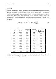
Lecture material – Environmental Hydraulic Simulation Page 61<br />
2.2.1.2 TURBULENT FLOWS<br />
We generally differentiate between a laminar and a turbulent <strong>flow</strong> state. If the <strong>flow</strong> velocity is very<br />
small, the <strong>flow</strong> will be laminar, and if the <strong>flow</strong> velocity exceeds a certain boundary value, the <strong>flow</strong><br />
becomes turbulent. Figure 2-14 shows this transition from a “well-ordered” laminar state to a<br />
seemingly stochastic and “chaotic” turbulent state for pipe <strong>flow</strong>. This experiment has already been<br />
done by Reynolds around 1860. Reynolds had then shown that the transition from laminar to turbulent<br />
can be described by the dimension-less Reynolds-number<br />
Re = u ⋅ L ν<br />
Eq. 2-134<br />
with u being the “typical“ velocity, L being the „typical“ characteristic length and ν being the<br />
kinematical viscosity. The characteristic length L is used for the description of fluid-transport<br />
processes (hydrodynamics, mass transport, heat transport, etc.) in so-called dimensionless index<br />
numbers, such as the Reynolds-number or Prandtl-number. It has the dimension of a length, but<br />
describes the three-dimensional geometry of a reference system. In simplified terms we apply for the<br />
characteristic length in the Reynolds number the diameter if there is a pipe <strong>flow</strong> or the water depth if<br />
we have an open channel <strong>flow</strong>.<br />
The critical Reynolds number for pipe <strong>flow</strong> is about 580, so that for example the <strong>flow</strong> within a pipe<br />
with the diameter D=0,20 m is turbulent if the <strong>flow</strong> velocity is greater than ∼ 3 mm/s. This observation<br />
makes clear that most of the <strong>flow</strong>s with technical relevance are turbulent. One of the few exceptions is<br />
for example human blood vessels that have laminar <strong>flow</strong> as a general rule (…maybe except for the<br />
aorta).<br />
Figure 2-14: Reynold’s experiment showing the transition from laminar to turbulent pipe <strong>flow</strong>, taken<br />
from [Van Dyke, 1982].
Lecture material – Environmental Hydraulic Simulation Page 62<br />
A turbulent <strong>flow</strong> can also be characterized by the following properties, according to [Ferziger et al.,<br />
1999] :<br />
- The process of turbulence is highly unsteady, so that e.g. the <strong>flow</strong> velocity at a given point is<br />
subject to great variance over time.<br />
- Turbulence is a three-dimensional phenomenon.<br />
- Vortices are an essential part of <strong>flow</strong>, and the interaction of vortices and the so-called vortex<br />
stretching are basic mechanisms that increase and widen turbulence.<br />
- The mixing processes due to common diffusion are often multiplied by turbulence.<br />
- The contact between fluid balls with small and large motion moment also increases because of the<br />
strong mixing processes. The acting viscous forces then lead to a loss of kinetic energy, while the<br />
loss is translated into inner energy, i.e. heat energy is produced. This process is thus irreversible<br />
and dissipative.<br />
- Newer examinations confirm the occurrence of so-called coherent structures. These are<br />
reproducible and deterministic processes, which have a big influence on the mixing processes.<br />
This list is very compressed, but it should make clear how complex turbulence is. Many mechanisms<br />
of the system are still unsolved, and the rather philosophical question comes up, if we will ever be able<br />
to understand the phenomenon turbulence completely and in detail. However, this is not necessary for<br />
many questions in engineering, since we are often only interested in average values. Additionally, we<br />
are also satisfied with solutions and approximations that are only valid within certain limits, as long as<br />
they describe our concrete problem in sufficient detail.<br />
Flows in open natural watercourses are always turbulent. There are two approaches of turbulence, the<br />
deterministic and statistical approach:<br />
Figure 2-15: Approaches of the turbulence description (according to Nikora, 2008)
Lecture material – Environmental Hydraulic Simulation Page 63<br />
Before we make the transition to numerical calculation approaches of turbulent <strong>flow</strong>, the terms vortex,<br />
vortex stretching and energy cascade shall be illustrated for better understanding of turbulence<br />
[Bradshaw, 1999].<br />
A simplified model that helps to understand a turbulent <strong>flow</strong> assumes the <strong>flow</strong> to be a superimposition<br />
of three-dimensional and locally unstable vortices unto a main <strong>flow</strong>. These vortices differ in geometric<br />
shape and size and are in direct interaction. When considering the coherent structures the vortex is,<br />
regardless of whether vertically or horizontally, or the turbulent <strong>flow</strong>, characterised by geometric<br />
shapes and decay processes. Coherent structures are three-dimensional <strong>flow</strong> zones in which at least<br />
one <strong>flow</strong> variable is receiving some significant correlation with itself or another variable in space and<br />
time. This means, that always one vortex is clearly visible in its rotational axis and the main direction<br />
of motion. On coherent structures, as shown in Figure 2-15 on the “burst” phenomenon, however,<br />
should not be addressed further.<br />
We are therefore considering the static point of view and the energy cascade concept. On the energy<br />
cascade initially one vertex is assumed, but which will collapse by vortex stretching into small<br />
vortexes [Bradshaw, 1999]. Vortex stretching is a deformation of the vortices making them smaller<br />
and adding kinetic energy to them. This kinetic energy is taken from the main <strong>flow</strong> or bigger vortices,<br />
depending on where the work is done. In the smallest vortices, the kinetic energy is transformed into<br />
heat energy (Figure 2-15, at the right). Fundamental examinations have shown in the last few years<br />
that this energy transport or better this energy cascade, beginning with the main <strong>flow</strong> over bigger<br />
vortices up to the smallest vortices, is no “one-way street”. Consequently, it can happen that the bigger<br />
vortices gain energy that comes from smaller vortices. In order to be able to estimate the importance of<br />
bigger and smaller vortices, we should have the following two aspects in mind:<br />
- The energy losses of the main <strong>flow</strong> (kinetic energy is taken) are caused by big vortices to a degree<br />
of about 90 %.<br />
- Energy dissipation only occurs in the smaller vortices.<br />
It can be seen why the big vortexes are of importance for example for the calculation of <strong>flow</strong> losses in<br />
rivers. They make up the main part of the <strong>flow</strong> losses caused by turbulence – we also speak of<br />
turbulent shear stresses that have an effect here.
Lecture material – Environmental Hydraulic Simulation Page 64<br />
2.2.1.2.1 APPROACHES OF NUMERICAL CALCULATIONS OF TURBULENT FLOWS<br />
<strong>Turbulent</strong> <strong>flow</strong>s are characterized by four main features: diffusion, dissipation, three-dimensionality<br />
and length scales. For the numerical calculation of turbulent <strong>flow</strong>s, an averaging of the Navier-Stokes<br />
equations of motion is carried out. The averaging can be done with different dimensions (compare<br />
Figure 2-16):<br />
• Averaging over time (assuming a statistically stationary <strong>flow</strong>) or averaging over a<br />
measurement (assuming constant boundary)<br />
• Averaging over a space direction, in which the average <strong>flow</strong> does not vary<br />
The following three approaches are applied most frequently in numerical calculation of turbulent<br />
<strong>flow</strong>s:<br />
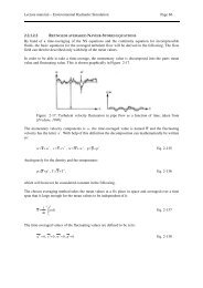
(1) The most frequent, but also most simple averaging is with respect to time. However, this approach<br />
is based on the assumption that the turbulent velocity fluctuations are distributed stochastically,<br />
meaning there is a constant mean <strong>flow</strong>. This averaging leads to the so-called Reynolds Averaged<br />
Navier-Stokes equations (short RANS). Additional terms with new variables occur in these<br />
partial differential equations because of the averaging. Consequently there are suddenly more<br />
variables than equations. In order to close the motion equation system, additional model equations<br />
or approximations have to be made, which express the variables as a function of the velocity field<br />
of the time-averaged <strong>flow</strong>. Setting up these model equations is a further research area with the<br />
name “turbulence modelling”.<br />
At the time averaging it can be differed between eddy-viscosity models and Reynolds-stress<br />
models. In the former case the turbulence is expressed by introducing an additional viscosity, the<br />
eddy viscosity. In Reynolds-stress models, the turbulence is considered through direct approaches<br />
to individual turbulent stress terms.<br />
(2) The Large Eddy Simulation (LES) does not model the big-scale turbulent structures anymore,<br />
but considers them in the direct solution of the NS equations. The influence of small-scale<br />
turbulent structures is calculated with help of turbulence models just as for the RANS approach.<br />
The main problem with LES is the determination of the limits for the size of vortices – which are<br />
big and which are small. The space- and time-discrete systems depend on it.<br />
(3) The Direct Numerical Simulation (DNS, not DANS!!) is the newest and most elaborate<br />
numerical approach. Turbulence modelling is not used here, but the NS equations are solved<br />
directly here. This requires a high space and time resolution of the simulation, what makes the<br />
calculation time-consuming and costly. Even large-scale parallel computer architectures can only<br />
calculate <strong>flow</strong>s with Reynolds numbers up to 200 today [Ferziger, 1999]. This is the absolute<br />
minimum for engineering and technical problems. There will not be a great change for the<br />
applicability of the DNS in the near future, so that it will most likely be limited to fundamental<br />
research issues.
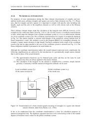
Lecture material – Environmental Hydraulic Simulation Page 65<br />
Figure 2-16: Basic equation and outline of the averaging in space and time<br />
The direct numerical simulation (DNS) without any model assumptions is very extensive, so usually<br />
the equations are resolved by the use of space or time averaged sizes. The spatial averaging (Large-<br />
Eddy Simulation = LES) requires because of the length scales very fine grid resolutions. The<br />
momentum transport smaller vortices is usually described by a simple algebraic relationship.<br />
Temporal averaging methods (Reynolds models = RANS) dissolve only the average <strong>flow</strong> and describe<br />
the impact of the turbulent <strong>flow</strong> through empirical approaches.<br />
The approaches LES and DNS will not be discussed in detail here, so the interested reader may refer<br />
to the respective technical literature. Only the RANS approach (1) will be further depicted. In the next<br />
chapter the time-averaged NS equations will be derived for this purpose.