Part II Implementation - FEniCS Project
Part II Implementation - FEniCS Project
Part II Implementation - FEniCS Project

Create successful ePaper yourself
Turn your PDF publications into a flip-book with our unique Google optimized e-Paper software.
Automated Scientific Computing<br />
Logg, Mardal, Wells (editors)<br />
This is a preliminary draft, June 9, 2009.<br />
Send comments and suggestions to fenics-book-dev@fenics.org.
Automated Scientific Computing<br />
The <strong>FEniCS</strong> Book<br />
Preliminary draft, June 9, 2009
And now that we may give final praise to the machine we may say that<br />
it will be desirable to all who are engaged in computations which, it<br />
is well known, are the managers of financial affairs, the administrators<br />
of others’ estates, merchants, surveyors, geographers, navigators,<br />
astronomers...For it is unworthy of excellent men to lose hours like<br />
slaves in the labor of calculations which could safely be relegated to<br />
anyone else if the machine were used.<br />
Gottfried Wilhelm Leibniz (1646–1716)
Contents<br />
1 Introduction<br />
By Anders Logg, Garth N. Wells and Kent-Andre Mardal 17<br />
2 A <strong>FEniCS</strong> Tutorial<br />
By Hans Petter Langtangen 19<br />
I Methodology 21<br />
3 The Finite Element Method<br />
By Robert C. Kirby and Anders Logg 23<br />
3.1 A Simple Model Problem . . . . . . . . . . . . . . . . . . . . . . . . . 23<br />
3.2 Finite Element Discretization . . . . . . . . . . . . . . . . . . . . . . 25<br />
3.2.1 Discretizing Poisson’s equation . . . . . . . . . . . . . . . . . 25<br />
3.2.2 Discretizing the first order system . . . . . . . . . . . . . . . 27<br />
3.3 Finite Element Abstract Formalism . . . . . . . . . . . . . . . . . . 28<br />
3.3.1 Linear problems . . . . . . . . . . . . . . . . . . . . . . . . . . 28<br />
3.3.2 Nonlinear problems . . . . . . . . . . . . . . . . . . . . . . . . 29<br />
3.4 Finite Element Function Spaces . . . . . . . . . . . . . . . . . . . . . 30<br />
3.4.1 The mesh . . . . . . . . . . . . . . . . . . . . . . . . . . . . . . 30<br />
3.4.2 The finite element definition . . . . . . . . . . . . . . . . . . . 32<br />
3.4.3 The nodal basis . . . . . . . . . . . . . . . . . . . . . . . . . . 32<br />
3.4.4 The local-to-global mapping . . . . . . . . . . . . . . . . . . . 33<br />
3.4.5 The global function space . . . . . . . . . . . . . . . . . . . . 34<br />
3.4.6 The mapping from the reference element . . . . . . . . . . . 36<br />
3.5 Finite Element Solvers . . . . . . . . . . . . . . . . . . . . . . . . . . 38<br />
3.6 Finite Element Error Estimation and Adaptivity . . . . . . . . . . . 39<br />
3.6.1 A priori error analysis . . . . . . . . . . . . . . . . . . . . . . 40<br />
7
3.6.2 A posteriori error analysis . . . . . . . . . . . . . . . . . . . . 41<br />
3.6.3 Adaptivity . . . . . . . . . . . . . . . . . . . . . . . . . . . . . 43<br />
3.7 Automating the Finite Element Method . . . . . . . . . . . . . . . . 44<br />
3.8 Outlook . . . . . . . . . . . . . . . . . . . . . . . . . . . . . . . . . . . 45<br />
3.9 Historical Notes . . . . . . . . . . . . . . . . . . . . . . . . . . . . . . 45<br />
4 Common and Unusual Finite Elements<br />
By Robert C. Kirby, Anders Logg and Andy R. Terrel 47<br />
4.1 Ciarlet’s Finite Element Definition . . . . . . . . . . . . . . . . . . . 47<br />
4.2 Notation . . . . . . . . . . . . . . . . . . . . . . . . . . . . . . . . . . 48<br />
4.3 The Argyris Element . . . . . . . . . . . . . . . . . . . . . . . . . . . 50<br />
4.3.1 Definition . . . . . . . . . . . . . . . . . . . . . . . . . . . . . . 50<br />
4.3.2 Historical notes . . . . . . . . . . . . . . . . . . . . . . . . . . 50<br />
4.4 The Brezzi–Douglas–Marini element . . . . . . . . . . . . . . . . . . 51<br />
4.4.1 Definition . . . . . . . . . . . . . . . . . . . . . . . . . . . . . . 51<br />
4.4.2 Historical notes . . . . . . . . . . . . . . . . . . . . . . . . . . 51<br />
4.5 The Crouzeix–Raviart element . . . . . . . . . . . . . . . . . . . . . 53<br />
4.5.1 Definition . . . . . . . . . . . . . . . . . . . . . . . . . . . . . . 53<br />
4.5.2 Historical notes . . . . . . . . . . . . . . . . . . . . . . . . . . 53<br />
4.6 The Hermite Element . . . . . . . . . . . . . . . . . . . . . . . . . . . 54<br />
4.6.1 Definition . . . . . . . . . . . . . . . . . . . . . . . . . . . . . . 54<br />
4.6.2 Historical notes . . . . . . . . . . . . . . . . . . . . . . . . . . 54<br />
4.7 The Lagrange Element . . . . . . . . . . . . . . . . . . . . . . . . . . 55<br />
4.7.1 Definition . . . . . . . . . . . . . . . . . . . . . . . . . . . . . . 55<br />
4.7.2 Historical notes . . . . . . . . . . . . . . . . . . . . . . . . . . 56<br />
4.8 The Morley Element . . . . . . . . . . . . . . . . . . . . . . . . . . . 57<br />
4.8.1 Definition . . . . . . . . . . . . . . . . . . . . . . . . . . . . . . 57<br />
4.8.2 Historical notes . . . . . . . . . . . . . . . . . . . . . . . . . . 57<br />
4.9 The Nédélec Element . . . . . . . . . . . . . . . . . . . . . . . . . . . 58<br />
4.9.1 Definition . . . . . . . . . . . . . . . . . . . . . . . . . . . . . . 58<br />
4.9.2 Historical notes . . . . . . . . . . . . . . . . . . . . . . . . . . 59<br />
4.10 The PEERS Element . . . . . . . . . . . . . . . . . . . . . . . . . . . 61<br />
4.10.1 Definition . . . . . . . . . . . . . . . . . . . . . . . . . . . . . . 61<br />
4.10.2 Historical notes . . . . . . . . . . . . . . . . . . . . . . . . . . 61<br />
4.11 The Raviart–Thomas Element . . . . . . . . . . . . . . . . . . . . . . 63<br />
4.11.1 Definition . . . . . . . . . . . . . . . . . . . . . . . . . . . . . . 63<br />
4.11.2 Historical notes . . . . . . . . . . . . . . . . . . . . . . . . . . 63<br />
4.12 Summary . . . . . . . . . . . . . . . . . . . . . . . . . . . . . . . . . . 65<br />
5 Constructing General Reference Finite Elements<br />
By Robert C. Kirby and Kent-Andre Mardal 69<br />
5.1 Introduction . . . . . . . . . . . . . . . . . . . . . . . . . . . . . . . . 69<br />
5.2 Preliminaries . . . . . . . . . . . . . . . . . . . . . . . . . . . . . . . 71<br />
8
5.3 Mathematical Framework . . . . . . . . . . . . . . . . . . . . . . . . 73<br />
5.3.1 Change of basis . . . . . . . . . . . . . . . . . . . . . . . . . . 73<br />
5.3.2 Polynomial spaces . . . . . . . . . . . . . . . . . . . . . . . . . 74<br />
5.4 Examples of Elements . . . . . . . . . . . . . . . . . . . . . . . . . . 76<br />
5.4.1 Bases for other polynomial spaces . . . . . . . . . . . . . . . 78<br />
5.5 Operations on the Polynomial spaces . . . . . . . . . . . . . . . . . . 80<br />
5.5.1 Evaluation . . . . . . . . . . . . . . . . . . . . . . . . . . . . . 80<br />
5.5.2 Differentiation . . . . . . . . . . . . . . . . . . . . . . . . . . . 80<br />
5.5.3 Integration . . . . . . . . . . . . . . . . . . . . . . . . . . . . . 81<br />
5.5.4 Linear functionals . . . . . . . . . . . . . . . . . . . . . . . . . 82<br />
6 Finite Element Variational Forms<br />
By Robert C. Kirby and Anders Logg 83<br />
7 Finite Element Assembly<br />
By Anders Logg 85<br />
8 Quadrature Representation of Finite Element Variational Forms<br />
By Kristian B. Ølgaard and Garth N. Wells 87<br />
9 Tensor Representation of Finite Element Variational Forms<br />
By Anders Logg and possibly others 89<br />
10 Discrete Optimization of Finite Element Matrix Evaluation<br />
By Robert C. Kirby, Matthew G. Knepley, Anders Logg, L. Ridgway Scott and<br />
Andy R. Terrel 91<br />
11 Parallel Adaptive Mesh Refinement<br />
By Johan Hoffman, Johan Jansson and Niclas Jansson 93<br />
11.1 A brief overview of parallel computing . . . . . . . . . . . . . . . . . 93<br />
11.2 Local mesh refinement . . . . . . . . . . . . . . . . . . . . . . . . . . 94<br />
11.2.1 The challenge of parallel mesh refinement . . . . . . . . . . 94<br />
11.2.2 A modified longest edge bisection algorithm . . . . . . . . . . 95<br />
11.3 The need of dynamic load balancing . . . . . . . . . . . . . . . . . . 97<br />
11.3.1 Workload modelling . . . . . . . . . . . . . . . . . . . . . . . . 98<br />
11.3.2 Remapping strategies . . . . . . . . . . . . . . . . . . . . . . . 99<br />
11.4 The implementation on a massively parallel system . . . . . . . . . 99<br />
11.4.1 The refinement method . . . . . . . . . . . . . . . . . . . . . . 100<br />
11.4.2 The remapping scheme . . . . . . . . . . . . . . . . . . . . . . 101<br />
11.4.3 Theoretical and experimental analysis . . . . . . . . . . . . . 102<br />
11.5 Summary and outlook . . . . . . . . . . . . . . . . . . . . . . . . . . 105<br />
9
<strong>II</strong> <strong>Implementation</strong> 107<br />
12 DOLFIN: A C++/Python Finite Element Library<br />
By Anders Logg and Garth N. Wells 109<br />
13 FFC: A Finite Element Form Compiler<br />
By Anders Logg and possibly others 111<br />
14 FErari: An Optimizing Compiler for Variational Forms<br />
By Robert C. Kirby and Anders Logg 113<br />
15 FIAT: Numerical Construction of Finite Element Basis Functions<br />
By Robert C. Kirby 115<br />
15.1 Introduction . . . . . . . . . . . . . . . . . . . . . . . . . . . . . . . . 115<br />
15.2 Prime basis: Collapsed-coordinate polynomials . . . . . . . . . . . . 116<br />
15.3 Representing polynomials and functionals . . . . . . . . . . . . . . . 117<br />
15.4 Other polynomial spaces . . . . . . . . . . . . . . . . . . . . . . . . . 120<br />
15.4.1 Supplemented polynomial spaces . . . . . . . . . . . . . . . . 121<br />
15.4.2 Constrained polynomial spaces . . . . . . . . . . . . . . . . . 121<br />
15.5 Conveying topological information to clients . . . . . . . . . . . . . . 122<br />
15.6 Functional evaluation . . . . . . . . . . . . . . . . . . . . . . . . . . . 123<br />
15.7 Overview of fundamental class structure . . . . . . . . . . . . . . . 124<br />
16 Instant: Just-in-Time Compilation of C/C++ Code in Python<br />
By Ilmar M. Wilbers, Kent-Andre Mardal and Martin S. Alnæs 127<br />
16.1 Introduction . . . . . . . . . . . . . . . . . . . . . . . . . . . . . . . . 127<br />
16.2 Examples . . . . . . . . . . . . . . . . . . . . . . . . . . . . . . . . . . 128<br />
16.2.1 Installing Instant . . . . . . . . . . . . . . . . . . . . . . . . . 128<br />
16.2.2 Hello World . . . . . . . . . . . . . . . . . . . . . . . . . . . . 129<br />
16.2.3 NumPy Arrays . . . . . . . . . . . . . . . . . . . . . . . . . . . 130<br />
16.2.4 Ordinary Differential Equations . . . . . . . . . . . . . . . . 130<br />
16.2.5 Numpy Arrays and OpenMP . . . . . . . . . . . . . . . . . . 132<br />
16.3 Instant Explained . . . . . . . . . . . . . . . . . . . . . . . . . . . . . 134<br />
16.3.1 Arrays and Typemaps . . . . . . . . . . . . . . . . . . . . . . 136<br />
16.3.2 Module name, signature, and cache . . . . . . . . . . . . . . 140<br />
16.3.3 Locking . . . . . . . . . . . . . . . . . . . . . . . . . . . . . . . 141<br />
16.4 Instant API . . . . . . . . . . . . . . . . . . . . . . . . . . . . . . . . . 141<br />
16.4.1 build module . . . . . . . . . . . . . . . . . . . . . . . . . . . . 141<br />
16.4.2 inline . . . . . . . . . . . . . . . . . . . . . . . . . . . . . . . . 146<br />
16.4.3 inline module . . . . . . . . . . . . . . . . . . . . . . . . . . . 146<br />
16.4.4 inline with numpy . . . . . . . . . . . . . . . . . . . . . . . . 146<br />
16.4.5 inline module with numpy . . . . . . . . . . . . . . . . . . . 146<br />
16.4.6 import module . . . . . . . . . . . . . . . . . . . . . . . . . . . 146<br />
16.4.7 header and libs from pkgconfig . . . . . . . . . . . . . . . . . 147<br />
10
16.4.8 get status output . . . . . . . . . . . . . . . . . . . . . . . . . 147<br />
16.4.9 get swig version . . . . . . . . . . . . . . . . . . . . . . . . . . 148<br />
16.4.10check swig version . . . . . . . . . . . . . . . . . . . . . . . . 148<br />
17 SyFi: Symbolic Construction of Finite Element Basis Functions<br />
By Martin S. Alnæs and Kent-Andre Mardal 149<br />
18 UFC: A Finite Element Code Generation Interface<br />
By Martin S. Alnæs, Anders Logg and Kent-Andre Mardal 151<br />
19 UFL: A Finite Element Form Language<br />
By Martin Sandve Alnæs 153<br />
19.1 Overview . . . . . . . . . . . . . . . . . . . . . . . . . . . . . . . . . . 154<br />
19.1.1 Design goals . . . . . . . . . . . . . . . . . . . . . . . . . . . . 154<br />
19.1.2 Motivational example . . . . . . . . . . . . . . . . . . . . . . . 155<br />
19.2 Defining finite element spaces . . . . . . . . . . . . . . . . . . . . . . 156<br />
19.3 Defining forms . . . . . . . . . . . . . . . . . . . . . . . . . . . . . . . 159<br />
19.4 Defining expressions . . . . . . . . . . . . . . . . . . . . . . . . . . . 160<br />
19.4.1 Form arguments . . . . . . . . . . . . . . . . . . . . . . . . . . 161<br />
19.4.2 Index notation . . . . . . . . . . . . . . . . . . . . . . . . . . . 162<br />
19.4.3 Algebraic operators and functions . . . . . . . . . . . . . . . 164<br />
19.4.4 Differential operators . . . . . . . . . . . . . . . . . . . . . . . 165<br />
19.4.5 Other operators . . . . . . . . . . . . . . . . . . . . . . . . . . 167<br />
19.5 Form operators . . . . . . . . . . . . . . . . . . . . . . . . . . . . . . 168<br />
19.5.1 Differentiating forms . . . . . . . . . . . . . . . . . . . . . . . 168<br />
19.5.2 Adjoint . . . . . . . . . . . . . . . . . . . . . . . . . . . . . . . 170<br />
19.5.3 Replacing functions . . . . . . . . . . . . . . . . . . . . . . . . 170<br />
19.5.4 Action . . . . . . . . . . . . . . . . . . . . . . . . . . . . . . . . 171<br />
19.5.5 Splitting a system . . . . . . . . . . . . . . . . . . . . . . . . . 171<br />
19.5.6 Computing the sensitivity of a function . . . . . . . . . . . . 171<br />
19.6 Expression representation . . . . . . . . . . . . . . . . . . . . . . . . 172<br />
19.6.1 The structure of an expression . . . . . . . . . . . . . . . . . 172<br />
19.6.2 Tree representation . . . . . . . . . . . . . . . . . . . . . . . . 173<br />
19.6.3 Expression node properties . . . . . . . . . . . . . . . . . . . 174<br />
19.6.4 Linearized graph representation . . . . . . . . . . . . . . . . 175<br />
19.6.5 <strong>Part</strong>itioning . . . . . . . . . . . . . . . . . . . . . . . . . . . . 176<br />
19.7 Computing derivatives . . . . . . . . . . . . . . . . . . . . . . . . . . 176<br />
19.7.1 Relations to form compiler approaches . . . . . . . . . . . . . 177<br />
19.7.2 Approaches to computing derivatives . . . . . . . . . . . . . . 178<br />
19.7.3 Forward mode Automatic Differentiation . . . . . . . . . . . 178<br />
19.7.4 Extensions to tensors and indexed expressions . . . . . . . . 179<br />
19.7.5 Higher order derivatives . . . . . . . . . . . . . . . . . . . . . 180<br />
19.7.6 Basic differentiation rules . . . . . . . . . . . . . . . . . . . . 181<br />
19.8 Algorithms . . . . . . . . . . . . . . . . . . . . . . . . . . . . . . . . . 183<br />
11
19.8.1 Effective tree traversal in Python . . . . . . . . . . . . . . . . 183<br />
19.8.2 Type based function dispatch in Python . . . . . . . . . . . . 183<br />
19.8.3 Implementing expression transformations . . . . . . . . . . 185<br />
19.8.4 Important transformations . . . . . . . . . . . . . . . . . . . 186<br />
19.8.5 Evaluating expressions . . . . . . . . . . . . . . . . . . . . . . 187<br />
19.8.6 Viewing expressions . . . . . . . . . . . . . . . . . . . . . . . 188<br />
19.9 <strong>Implementation</strong> issues . . . . . . . . . . . . . . . . . . . . . . . . . . 188<br />
19.9.1 Python as a basis for a domain specific language . . . . . . . 188<br />
19.9.2 Ensuring unique form signatures . . . . . . . . . . . . . . . . 189<br />
19.9.3 Efficiency considerations . . . . . . . . . . . . . . . . . . . . . 190<br />
19.10Future directions . . . . . . . . . . . . . . . . . . . . . . . . . . . . . 190<br />
19.11Acknowledgements . . . . . . . . . . . . . . . . . . . . . . . . . . . . 191<br />
20 Unicorn: A Unified Continuum Mechanics Solver<br />
By Johan Hoffman, Johan Jansson, Niclas Jansson and Murtazo Nazarov 193<br />
20.1 Unified Continuum modeling . . . . . . . . . . . . . . . . . . . . . . 194<br />
20.1.1 Automated computational modeling and software design . . 195<br />
20.2 Space-time General Galerkin discretization . . . . . . . . . . . . . . 195<br />
20.2.1 Standard Galerkin . . . . . . . . . . . . . . . . . . . . . . . . 196<br />
20.2.2 Local ALE . . . . . . . . . . . . . . . . . . . . . . . . . . . . . 196<br />
20.2.3 Streamline diffusion stabilization . . . . . . . . . . . . . . . . 197<br />
20.2.4 Duality-based adaptive error control . . . . . . . . . . . . . . 197<br />
20.2.5 Unicorn/<strong>FEniCS</strong> software implementation . . . . . . . . . . 197<br />
20.3 Unicorn classes: data types and algorithms . . . . . . . . . . . . . . 198<br />
20.3.1 Unicorn software design . . . . . . . . . . . . . . . . . . . . . 198<br />
20.3.2 TimeDependentPDE . . . . . . . . . . . . . . . . . . . . . . . 199<br />
20.3.3 ErrorEstimate . . . . . . . . . . . . . . . . . . . . . . . . . 200<br />
20.3.4 SlipBC . . . . . . . . . . . . . . . . . . . . . . . . . . . . . . . 202<br />
20.4 Mesh adaptivity . . . . . . . . . . . . . . . . . . . . . . . . . . . . . . 203<br />
20.4.1 Local mesh operations: Madlib . . . . . . . . . . . . . . . . . 203<br />
20.4.2 Elastic mesh smoothing: cell quality optimization . . . . . . 203<br />
20.4.3 Recusive Rivara bisection . . . . . . . . . . . . . . . . . . . . 203<br />
20.5 Parallel computation . . . . . . . . . . . . . . . . . . . . . . . . . . . 203<br />
20.5.1 Tensor assembly . . . . . . . . . . . . . . . . . . . . . . . . . . 203<br />
20.5.2 Mesh refinement . . . . . . . . . . . . . . . . . . . . . . . . . 203<br />
20.6 Application examples . . . . . . . . . . . . . . . . . . . . . . . . . . . 203<br />
20.6.1 Incompressible flow . . . . . . . . . . . . . . . . . . . . . . . . 203<br />
20.6.2 Compressible flow . . . . . . . . . . . . . . . . . . . . . . . . . 203<br />
20.6.3 Fluid-structure interaction . . . . . . . . . . . . . . . . . . . 203<br />
21 Viper: A Minimalistic Scientific Plotter<br />
By Ola Skavhaug 207<br />
12
22 Lessons Learnt in Mixed Language Programming<br />
By Kent-Andre Mardal, Anders Logg, and Ola Skavhaug 209<br />
<strong>II</strong>I Applications 211<br />
23 Finite Elements for Incompressible Fluids<br />
By Andy R. Terrel, L. Ridgway Scott, Matthew G. Knepley, Robert C. Kirby and<br />
Garth N. Wells 213<br />
24 Benchmarking Finite Element Methods for Navier–Stokes<br />
By Kristian Valen-Sendstad, Anders Logg and Kent-Andre Mardal 215<br />
25 Image-Based Computational Hemodynamics<br />
By Luca Antiga 217<br />
26 Simulating the Hemodynamics of the Circle of Willis<br />
By Kristian Valen-Sendstad, Kent-Andre Mardal and Anders Logg 219<br />
27 Cerebrospinal Fluid Flow<br />
By Susanne Hentschel, Svein Linge, Emil Alf Løvgren and Kent-Andre Mardal 221<br />
27.1 Medical Background . . . . . . . . . . . . . . . . . . . . . . . . . . . 221<br />
27.2 Mathematical Description . . . . . . . . . . . . . . . . . . . . . . . . 223<br />
27.3 Numerical Experiments . . . . . . . . . . . . . . . . . . . . . . . . . 223<br />
27.3.1 <strong>Implementation</strong> . . . . . . . . . . . . . . . . . . . . . . . . . . 223<br />
27.3.2 Example 1. Simulation of a Pulse in the SAS. . . . . . . . . . 230<br />
27.3.3 Example 2. Simplified Boundary Conditions. . . . . . . . . . 234<br />
27.3.4 Example 3. Cord Shape and Position. . . . . . . . . . . . . . 235<br />
27.3.5 Example 4. Cord with Syrinx. . . . . . . . . . . . . . . . . . . 236<br />
28 Turbulent Flow and Fluid–Structure Interaction with Unicorn<br />
By Johan Hoffman, Johan Jansson, Niclas Jansson, Claes Johnson and Murtazo<br />
Nazarov 239<br />
28.1 Introduction . . . . . . . . . . . . . . . . . . . . . . . . . . . . . . . . 239<br />
28.2 Continuum models . . . . . . . . . . . . . . . . . . . . . . . . . . . . 240<br />
28.3 Mathematical framework . . . . . . . . . . . . . . . . . . . . . . . . 241<br />
28.4 Computational method . . . . . . . . . . . . . . . . . . . . . . . . . . 241<br />
28.5 Boundary conditions . . . . . . . . . . . . . . . . . . . . . . . . . . . 241<br />
28.6 Geometry modeling . . . . . . . . . . . . . . . . . . . . . . . . . . . . 242<br />
28.7 Fluid-structure interaction . . . . . . . . . . . . . . . . . . . . . . . . 242<br />
28.8 Applications . . . . . . . . . . . . . . . . . . . . . . . . . . . . . . . . 242<br />
28.8.1 Turbulent flow separation . . . . . . . . . . . . . . . . . . . . 242<br />
28.8.2 Flight aerodynamics . . . . . . . . . . . . . . . . . . . . . . . 242<br />
28.8.3 Vehicle aerodynamics . . . . . . . . . . . . . . . . . . . . . . . 242<br />
28.8.4 Biomedical flow . . . . . . . . . . . . . . . . . . . . . . . . . . 242<br />
13
28.8.5 Aeroacoustics . . . . . . . . . . . . . . . . . . . . . . . . . . . 242<br />
28.8.6 Gas flow . . . . . . . . . . . . . . . . . . . . . . . . . . . . . . 243<br />
28.9 References . . . . . . . . . . . . . . . . . . . . . . . . . . . . . . . . . 243<br />
29 Fluid–Structure Interaction using Nitsche’s Method<br />
By Kristoffer Selim and Anders Logg 245<br />
30 Improved Boussinesq Equations for Surface Water Waves<br />
By N. Lopes, P. Pereira and L. Trabucho 247<br />
30.1 Introduction . . . . . . . . . . . . . . . . . . . . . . . . . . . . . . . . 247<br />
30.2 Model derivation . . . . . . . . . . . . . . . . . . . . . . . . . . . . . . 249<br />
30.2.1 Standard models . . . . . . . . . . . . . . . . . . . . . . . . . 251<br />
30.2.2 Second-order model . . . . . . . . . . . . . . . . . . . . . . . . 253<br />
30.3 Linear dispersion relation . . . . . . . . . . . . . . . . . . . . . . . . 253<br />
30.4 Wave generation . . . . . . . . . . . . . . . . . . . . . . . . . . . . . . 255<br />
30.4.1 Initial condition . . . . . . . . . . . . . . . . . . . . . . . . . . 255<br />
30.4.2 Incident wave . . . . . . . . . . . . . . . . . . . . . . . . . . . 256<br />
30.4.3 Source function . . . . . . . . . . . . . . . . . . . . . . . . . . 256<br />
30.5 Reflective walls and sponge layers . . . . . . . . . . . . . . . . . . . 257<br />
30.6 Numerical Methods . . . . . . . . . . . . . . . . . . . . . . . . . . . . 257<br />
30.7 Numerical Applications . . . . . . . . . . . . . . . . . . . . . . . . . . 259<br />
30.8 Conclusions and future work . . . . . . . . . . . . . . . . . . . . . . 260<br />
30.9 Acknowledgments . . . . . . . . . . . . . . . . . . . . . . . . . . . . . 262<br />
31 Multiphase Flow Through Porous Media<br />
By Xuming Shan and Garth N. Wells 263<br />
32 Computing the Mechanics of the Heart<br />
By Martin S. Alnæs, Kent-Andre Mardal and Joakim Sundnes 265<br />
33 Simulation of Ca 2+ Dynamics in the Dyadic Cleft<br />
By Johan Hake 267<br />
33.1 Introduction . . . . . . . . . . . . . . . . . . . . . . . . . . . . . . . . 267<br />
33.2 Biological background . . . . . . . . . . . . . . . . . . . . . . . . . . 268<br />
33.3 Mathematical models . . . . . . . . . . . . . . . . . . . . . . . . . . . 268<br />
33.3.1 Geometry . . . . . . . . . . . . . . . . . . . . . . . . . . . . . . 268<br />
33.3.2 Ca 2+ Diffusion . . . . . . . . . . . . . . . . . . . . . . . . . . . 269<br />
33.3.3 Stochastic models of single channels . . . . . . . . . . . . . . 271<br />
33.4 Numerical methods for the continuous system . . . . . . . . . . . . 272<br />
33.4.1 Discretization . . . . . . . . . . . . . . . . . . . . . . . . . . . 274<br />
33.4.2 Stabilization . . . . . . . . . . . . . . . . . . . . . . . . . . . . 276<br />
33.5 diffsim an event driven simulator . . . . . . . . . . . . . . . . . . 280<br />
33.5.1 Stochastic system . . . . . . . . . . . . . . . . . . . . . . . . . 280<br />
33.5.2 Time stepping algorithm . . . . . . . . . . . . . . . . . . . . . 281<br />
14
33.5.3 diffsim an example . . . . . . . . . . . . . . . . . . . . . . . 282<br />
34 Electromagnetic Waveguide Analysis<br />
By Evan Lezar and David B. Davidson 289<br />
34.1 Formulation . . . . . . . . . . . . . . . . . . . . . . . . . . . . . . . . 290<br />
34.1.1 Waveguide Cutoff Analysis . . . . . . . . . . . . . . . . . . . 291<br />
34.1.2 Waveguide Dispersion Analysis . . . . . . . . . . . . . . . . . 293<br />
34.2 <strong>Implementation</strong> . . . . . . . . . . . . . . . . . . . . . . . . . . . . . . 294<br />
34.2.1 Formulation . . . . . . . . . . . . . . . . . . . . . . . . . . . . 294<br />
34.2.2 Post-Processing . . . . . . . . . . . . . . . . . . . . . . . . . . 296<br />
34.3 Examples . . . . . . . . . . . . . . . . . . . . . . . . . . . . . . . . . . 297<br />
34.3.1 Hollow Rectangular Waveguide . . . . . . . . . . . . . . . . . 298<br />
34.3.2 Half-Loaded Rectangular Waveguide . . . . . . . . . . . . . . 301<br />
34.3.3 Shielded Microstrip . . . . . . . . . . . . . . . . . . . . . . . . 303<br />
34.4 Analysis of Waveguide Discontinuities . . . . . . . . . . . . . . . . . 305<br />
34.5 Conclusion . . . . . . . . . . . . . . . . . . . . . . . . . . . . . . . . . 307<br />
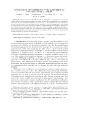
35 Applications in Solid Mechanics<br />
By Kristian B. Ølgaard and Garth N. Wells 309<br />
36 Modelling Evolving Discontinuities<br />
By Mehdi Nikbakht and Garth N. Wells 311<br />
37 Optimal Control Problems<br />
By Kent-Andre Mardal, Oddrun Christine Myklebust and Bjørn Fredrik Nielsen313<br />
38 Automatic Calibration of Depositional Models<br />
By Hans Joachim Schroll 315<br />
38.1 Issues in dual lithology sedimentation . . . . . . . . . . . . . . . . . 315<br />
38.2 A multidimensional sedimentation model . . . . . . . . . . . . . . . 316<br />
38.3 An inverse approach . . . . . . . . . . . . . . . . . . . . . . . . . . . 316<br />
38.4 The Landweber algorithm . . . . . . . . . . . . . . . . . . . . . . . . 317<br />
38.5 Evaluation of gradients by duality arguments . . . . . . . . . . . . 318<br />
38.6 Aspects of the implementation . . . . . . . . . . . . . . . . . . . . . . 320<br />
38.7 Numerical experiments . . . . . . . . . . . . . . . . . . . . . . . . . . 321<br />
38.8 Results and conclusion . . . . . . . . . . . . . . . . . . . . . . . . . . 323<br />
39 Computational Thermodynamics<br />
By Johan Hoffman, Claes Johnson and Murtazo Nazarov 331<br />
39.1 <strong>FEniCS</strong> as Computational Science . . . . . . . . . . . . . . . . . . . 331<br />
39.2 The 1st and 2nd Laws of Thermodynamics . . . . . . . . . . . . . . 332<br />
39.3 The Enigma . . . . . . . . . . . . . . . . . . . . . . . . . . . . . . . . 333<br />
39.4 Computational Foundation . . . . . . . . . . . . . . . . . . . . . . . . 335<br />
39.5 Viscosity Solutions . . . . . . . . . . . . . . . . . . . . . . . . . . . . 337<br />
39.6 Joule’s 1845 Experiment . . . . . . . . . . . . . . . . . . . . . . . . . 338<br />
15
39.7 The Euler Equations . . . . . . . . . . . . . . . . . . . . . . . . . . . 339<br />
39.8 Energy Estimates for Viscosity Solutions . . . . . . . . . . . . . . . 340<br />
39.9 Compression and Expansion . . . . . . . . . . . . . . . . . . . . . . . 342<br />
39.10A 2nd Law witout Entropy . . . . . . . . . . . . . . . . . . . . . . . . 342<br />
39.11Comparison with Classical Thermodynamics . . . . . . . . . . . . . 343<br />
39.12EG2 . . . . . . . . . . . . . . . . . . . . . . . . . . . . . . . . . . . . . 344<br />
39.13The 2nd Law for EG2 . . . . . . . . . . . . . . . . . . . . . . . . . . . 345<br />
39.14The Stabilization in EG2 . . . . . . . . . . . . . . . . . . . . . . . . . 345<br />
39.15Output Uniqueness and Stability . . . . . . . . . . . . . . . . . . . . 345<br />
40 Saddle Point Stability<br />
By Marie E. Rognes 347<br />
A Notation 359<br />
16
CHAPTER1<br />
Introduction<br />
By Anders Logg, Garth N. Wells and Kent-Andre Mardal<br />
Chapter ref: [intro]<br />
17
CHAPTER2<br />
A <strong>FEniCS</strong> Tutorial<br />
By Hans Petter Langtangen<br />
Chapter ref: [langtangen]<br />
A series of complete, worked out examples, starting with simple mathematical<br />
PDE problems, progressing with physics/mechanics problems, and ending up<br />
with advanced computational mechanics problems. The essence is to show that<br />
theprogrammingtasksscalewiththemathematicalformulationoftheproblems.<br />
19
<strong>Part</strong> I<br />
Methodology<br />
21
CHAPTER3<br />
The Finite Element Method<br />
By Robert C. Kirby and Anders Logg<br />
Chapter ref: [kirby-7]<br />
The finite element method has grown out of Galerkin’s method, emerging as<br />
auniversal methodforthesolutionofdifferential equations. Much ofthesuccess<br />
of the finite element method can be contributed to its generality and simplicity,<br />
allowing a wide range of differential equations from all areas of science to be<br />
analyzedandsolvedwithinacommonframework. Anothercontributingfactorto<br />
thesuccessofthefiniteelementmethodistheflexibility offormulation, allowing<br />
thepropertiesofthediscretization to be controlledbythe choice offiniteelement<br />
approximating spaces.<br />
Inthischapter,wereviewthefiniteelementmethodandintroducesomebasic<br />
conceptsandnotation. Inthecomingchapters,wediscusstheseconceptsinmore<br />
detail,withaparticularfocusontheimplementationandautomationofthefinite<br />
element method as part of the <strong>FEniCS</strong> project.<br />
3.1 A Simple Model Problem<br />
In 1813, Siméon Denis Poisson (Figure 3.1) published in Bulletin de la société<br />
philomatique his famous equation as a correction of an equation published earlier<br />
by Pierre-Simon Laplace. Poisson’s equation is a second-order partial differential<br />
equation stating that the negative Laplacian −∆u of some unknown field<br />
u = u(x) is equal to a given function f = f(x) on a domain Ω ⊂ R d , possibly<br />
amended by a set of boundary conditions for the solution u on the boundary ∂Ω<br />
23
The Finite Element Method<br />
Figure 3.1: Siméon Denis Poisson (1781–1840), inventor of Poisson’s equation.<br />
of Ω:<br />
−∆u = f in Ω,<br />
u = u 0 on Γ D ⊂ ∂Ω,<br />
−∂ n u = g on Γ N ⊂ ∂Ω.<br />
(3.1)<br />
The Dirichlet boundary condition u = u 0 signifies a prescribed value for the unknown<br />
u on a subset Γ D of the boundary and the Neumann boundary condition<br />
−∂ n u = g signifies a prescribed value for the (negative) normal derivative of u<br />
on the remaining boundary Γ N = ∂Ω \ Γ D . Poisson’s equation is a simple model<br />
for gravity, electromagnetism, heat transfer, fluid flow, and many other physical<br />
processes. It also appears as the basic building block in a large number of more<br />
complex physical models, including the Navier–Stokes equations that we return<br />
to below in Chapters ??.<br />
To derive Poisson’s equation (3.1), we may consider a model for the temperature<br />
uinabodyoccupyingadomain Ωsubjecttoaheatsource f. Letting σ = σ(x)<br />
denote heat flux, it follows by conservation of energy that the outflow of energy<br />
over the boundary ∂ω of any test volume ω ⊂ Ω must be balanced by the energy<br />
transferred from the heat source f,<br />
∫ ∫<br />
σ · n ds = f dx.<br />
Integrating by parts, it follows that<br />
∫ ∫<br />
∇ · σ dx =<br />
∂ω<br />
ω<br />
forall testvolumes ω and thusthat ∇ ·σ = f (by suitable regularity assumptions<br />
on σ and f). If we now make the assumption that the heat flux σ is proportional<br />
24<br />
ω<br />
ω<br />
f dx
Robert C. Kirby and Anders Logg<br />
Figure 3.2: Poisson’s equation is a simple consequence of balance of energy in an<br />
arbitrary test volume ω ⊂ Ω.<br />
to the negative gradient of the temperature u (Fourier’s law),<br />
σ = −κ∇u,<br />
we arrive at the following system of equations:<br />
∇ · σ = f in Ω,<br />
σ + ∇u = 0 in Ω,<br />
(3.2)<br />
where we have assumed that the the heat conductivity κ = 1. Replacing σ in<br />
the first of these equations by −∇u, we arrive at Poisson’s equation (3.1). We<br />
note that one may as well arrive at the system of first order equations (3.2) by<br />
introducing σ = −∇u as an auxiliary variable in the second order equation (3.1).<br />
We also note that the Dirichlet and Neumann boundary conditions in (3.1) correspond<br />
to prescribed values for the temperature and heat flux respectively.<br />
3.2 Finite Element Discretization<br />
3.2.1 Discretizing Poisson’s equation<br />
To discretize Poisson’s equation (3.1) by the finite element method, we first multiply<br />
by a test function v and integrate by parts to obtain<br />
∫<br />
∫ ∫<br />
∇v · ∇u dx − v ∂ n u ds = vf dx.<br />
Ω<br />
Ω<br />
Ω<br />
25
The Finite Element Method<br />
Letting the test function v vanish on the Dirichlet boundary Γ D where the solution<br />
u is known, we arrive at the following classical variational problem: Find<br />
u ∈ V such that<br />
∫<br />
∫ ∫<br />
∇v · ∇u dx = vf dx − v g ds ∀v ∈ ˆV . (3.3)<br />
Ω<br />
Ω Γ N<br />
The test space ˆV is defined by<br />
ˆV = {v ∈ H 1 (Ω) : v = 0 on Γ D },<br />
and the trial space V contains members of ˆV shifted by the Dirichlet condition,<br />
V = {v ∈ H 1 (Ω) : v = u 0 on Γ D }.<br />
We may now discretize Poisson’s equation by restricting the variational problem<br />
(3.3) to a pair of discrete spaces: Find u h ∈ V h ⊂ V such that<br />
∫<br />
∫ ∫<br />
∇v · ∇u h dx = vf dx − v g ds ∀v ∈ ˆV h ⊂ ˆV . (3.4)<br />
Ω<br />
Ω Γ N<br />
WenoteherethattheDirichletcondition u = u 0 on Γ D entersintothedefinitionof<br />
the trial space V h (it is an essential boundary condition), whereas the Neumann<br />
condition −∂ n u = g on Γ N enters into the variational problem (it is a natural<br />
boundary condition).<br />
To solve the discrete variational problem (3.4), we must construct a suitable<br />
pair of discrete test and trial spaces ˆV h and V h . We return to this issue below, but<br />
assume for now that we have a basis {ˆφ i } N i=1 for ˆV h and a basis {φ j } N j=1 for V h. We<br />
may then make an ansatz for u h in termsofthe basis functionsof the trial space,<br />
N∑<br />
u h = U j φ j ,<br />
j=1<br />
where U ∈ R N is the vector of degrees of freedom to be computed. Inserting this<br />
into (3.4) and varying the test function v over the basis functions of the discrete<br />
test space ˆV h , we obtain<br />
N∑<br />
∫<br />
∫ ∫<br />
U j ∇ˆφ i · ∇φ j dx = ˆφ i f dx − ˆφi g ds, i = 1, 2, . . .,N.<br />
Ω<br />
Ω Γ N<br />
j=1<br />
We may thus compute the finite element solution u h = ∑ N<br />
j=1 U jφ j by solving the<br />
linear system<br />
AU = b,<br />
where<br />
∫<br />
A ij =<br />
∫<br />
b i =<br />
Ω<br />
Ω<br />
∇ˆφ i · ∇φ j dx,<br />
∫<br />
ˆφ i f dx − ˆφi g ds.<br />
Γ N<br />
26
Robert C. Kirby and Anders Logg<br />
3.2.2 Discretizing the first order system<br />
We may similarly discretize the first order system (3.2) by multiplying the first<br />
equation by a test function v and the second by a test function τ. Summing up<br />
and integrating by parts, we find<br />
∫<br />
∫ ∫<br />
v∇ · σ + τ · σ − ∇ · τ u dx + τ · n u ds = vf dx ∀v ∈ ˆV .<br />
Ω<br />
∂Ω<br />
The normal flux σ ·n = g is knownon the Neumann boundary Γ N so we maytake<br />
τ · n = 0 on Γ N . Inserting the value for u on the Dirichlet boundary Γ D , we thus<br />
arrive at the following variational problem: Find (u, σ) ∈ V such that<br />
∫<br />
∫ ∫<br />
v∇ · σ + τ · σ − ∇ · τ u dx = vf dx − τ · n u 0 ds ∀(v, τ) ∈ ˆV . (3.5)<br />
Ω<br />
Ω Γ D<br />
Now, ˆV and V are a pair of suitable test and trial spaces, here<br />
ˆV = {(v, τ) : v ∈ L 2 (Ω), τ ∈ H(div; Ω), τ · n = 0 on Γ N },<br />
V = {(v, τ) : v ∈ L 2 (Ω), τ ∈ H(div; Ω), τ · n = g on Γ N }.<br />
As above, we restrict this variational problem to a pair of discrete test and<br />
trialspaces ˆV h ⊂ ˆV and V h ⊂ V andmakeanansatzforthefiniteelementsolution<br />
of the form<br />
N∑<br />
(u h , σ h ) = U j (φ j , ψ j ),<br />
j=1<br />
where {(φ j , ψ j )} N j=1 is a basis for the trial space V h. Typically, either φ j or ψ j will<br />
vanish, so that the basis is really the tensor product of a basis for an L 2 space<br />
with an H(div) space. We thus obtain a linear system for the degrees of freedom<br />
U ∈ R N by solving a linear system AU = b, where now<br />
∫<br />
A ij = ˆφ i ∇ · ψ j + ˆψ i · ψ j − ∇ · ˆψ i φ j dx,<br />
∫Ω<br />
∫<br />
b i = ˆφ i f dx − ˆψi · n u 0 ds.<br />
Ω Γ D<br />
We note that the variational problem (3.5) differs from the variational problem<br />
(3.3) in that the Dirichlet condition u = u 0 on Γ D enters into the variational<br />
formulation(itisnowanaturalboundarycondition), whereastheNeumanncondition<br />
σ = g on Γ N enters into the definition of the trial space V (it is now an<br />
essential boundary condition).<br />
Such mixed methods require some care in selecting spaces that discretize L 2<br />
and H(div) in a compatible way. Stable discretizations must satisfy the so-called<br />
inf–sup or Ladysenskaja–Babuška–Brezzi (LBB) condition. This theory explains<br />
why many of the elements for mixed methods seem complicated compared to<br />
those for standard Galerkin methods.<br />
27<br />
Ω
The Finite Element Method<br />
3.3 Finite Element Abstract Formalism<br />
3.3.1 Linear problems<br />
We saw above that the finite element solution of Poisson’s equation (3.1) or (3.2)<br />
can be obtained by restricting an infinite dimensional variational problem to a<br />
finite dimensional variational problem and solving a linear system.<br />
To formalize this, we consider a general linear variational problem written in<br />
the following canonical form: Find u ∈ V such that<br />
a(v, u) = L(v) ∀v ∈ ˆV , (3.6)<br />
where ˆV is the test space and V is the trial space. We may thus express the<br />
variational problem in terms of a bilinear form a and linear form (functional) L,<br />
a : ˆV × V → R,<br />
L : ˆV → R.<br />
As above, we discretize the variational problem (3.6) by restricting to a pair of<br />
discrete test and trial spaces: Find u h ∈ V h ⊂ V such that<br />
a(v, u h ) = L(v) ∀v ∈ ˆV h ⊂ ˆV . (3.7)<br />
To solve the discrete variational problem (3.7), we make an ansatz of the form<br />
u h =<br />
N∑<br />
U j φ j , (3.8)<br />
j=1<br />
and take v = ˆφ i , i = 1, 2, . . ., N, where {ˆφ i } N i=1 is a basis for the discrete test<br />
space ˆV h and {φ j } N j=1 is a basis for the discrete trial space V h. It follows that<br />
N∑<br />
U j a(ˆφ i , φ j ) = L(ˆφ i ), i = 1, 2, . . ., N.<br />
j=1<br />
We thus obtain the degrees of freedom U of the finite element solution u h by<br />
solving a linear system AU = b, where<br />
A ij = a(ˆφ i , φ j ), i, j = 1, 2, . . ., N,<br />
b i = L(ˆφ i ).<br />
(3.9)<br />
28
Robert C. Kirby and Anders Logg<br />
3.3.2 Nonlinear problems<br />
We also consider nonlinear variational problems written in the following canonical<br />
form: Find u ∈ V such that<br />
F(u; v) = 0 ∀v ∈ ˆV , (3.10)<br />
where now F : V × ˆV → R is a semilinear form, linear in the argument(s) subsequent<br />
to the semicolon. As above, we discretize the variational problem (3.10) by<br />
restricting to a pair of discrete test and trial spaces: Find u h ∈ V h ⊂ V such that<br />
F(u h ; v) = 0 ∀v ∈ ˆV h ⊂ ˆV .<br />
The finite element solution u h = ∑ N<br />
j=1 U jφ j may then be computed by solving a<br />
nonlinear system of equations,<br />
b(U) = 0, (3.11)<br />
where b : R N → R N and<br />
b i (U) = F(u h ; ˆφ i ), i = 1, 2, . . ., N. (3.12)<br />
To solve the nonlinear system (3.11) by Newton’s method or some variant of<br />
Newton’smethod,wecomputetheJacobian A = b ′ . Wenotethatifthesemilinear<br />
form F is differentiable in u, then the entries of the Jacobian A are given by<br />
A ij (u h ) = ∂b i(U)<br />
∂U j<br />
= ∂<br />
∂U j<br />
F(u h ; ˆφ i ) = F ′ (u h ; ˆφ i ) ∂u h<br />
∂U j<br />
= F ′ (u h ; ˆφ i ) φ j ≡ F ′ (u h ; ˆφ i , φ j ).<br />
(3.13)<br />
In each Newton iteration, we must then evaluate (assemble) the matrix A and<br />
the vector b, and update the solution vector U by<br />
where δU k solves the linear system<br />
U k+1 = U k − δU k ,<br />
A(u k h ) δUk = b(u k h ). (3.14)<br />
Wenotethatforeachfixed u h , a = F ′ (u h ; ·, ·)isabilinear formand L = F(u h ; ·)<br />
is a linear form. In each Newton iteration, we thus solve a linear variational<br />
problem of the canonical form (3.6): Find δu ∈ V 0 such that<br />
F ′ (u h ; v, δu) = F(u h ; v) ∀v ∈ ˆV , (3.15)<br />
where V 0 = {v − w : v, w ∈ V }. Discretizing (3.15) as in Section 3.3.1, we recover<br />
the linear system (3.14).<br />
29
The Finite Element Method<br />
Example 3.1 (Nonlinear Poisson equation). As an example, consider the following<br />
nonlinear Poisson equation:<br />
−∇ · ((1 + u)∇u) = f in Ω,<br />
u = 0<br />
on ∂Ω.<br />
(3.16)<br />
Multiplying (3.16) with a test function v and integrating by parts, we obtain<br />
∫<br />
∫<br />
∇v · ((1 + u)∇u) dx = vf dx,<br />
Ω<br />
which is a nonlinear variational problem of the form (3.10), with<br />
∫<br />
∫<br />
F(u; v) = ∇v · ((1 + u)∇u) dx − v f dx.<br />
Ω<br />
Linearizing the semilinear form F around u = u h , we obtain<br />
∫<br />
∫<br />
F ′ (u h ; v, δu) = ∇v · (δu∇u h ) dx + ∇v · ((1 + u h )∇δu) dx.<br />
Ω<br />
We may thus compute the entries of the Jacobian matrix A(u h ) by<br />
∫<br />
∫<br />
A ij (u h ) = F ′ (u h ; ˆφ i , φ j ) = ∇ˆφ i · (φ j ∇u h ) dx + ∇ˆφ i · ((1 + u h )∇φ j ) dx. (3.17)<br />
3.4 Finite Element Function Spaces<br />
Ω<br />
In the above discussion, we assumed that we could construct discrete subspaces<br />
V h ⊂ V of infinite dimensional function spaces. A central aspect of the finite<br />
element method is the construction of such subspaces by patching together local<br />
function spaces defined on a set of finite elements. We here give a general<br />
overview of the construction of finite element function spaces and return below<br />
inChapters4and5totheconstructionofspecificfunctionspacessuchassubsets<br />
of H 1 (Ω), H(curl), H(div) and L 2 (Ω).<br />
3.4.1 The mesh<br />
To define V h , we first partition the domain Ω into a finite set of disjoint cells<br />
T = {K} such that<br />
∪ K∈T K = Ω.<br />
Together, these cells form a mesh of the domain Ω. The cells are typically simple<br />
polygonal shapes like intervals, triangles, quadrilaterals, tetrahedra or hexahedra<br />
as shown in Figure 3.3. But other shapes are possible, in particular curved<br />
cells to correctly capture the boundary of a non-polygonal domain as shown in<br />
Figure 3.4.<br />
30<br />
Ω<br />
Ω<br />
Ω<br />
Ω
Robert C. Kirby and Anders Logg<br />
Figure 3.3: Finite element cells in one, two and three space dimensions.<br />
Figure 3.4: A straight triangular cell (left) and curved triangular cell (right).<br />
31
The Finite Element Method<br />
3.4.2 The finite element definition<br />
Once a domain Ω has been partitioned into cells, one may define a local function<br />
space P K on each cell K and use these local function spaces to build the global<br />
function space V h . A cell K together with a local function space P K and a set of<br />
rules for describing functions in P K is called a finite element. This definition of<br />
finite element was first formalized by Ciarlet in [Cia78, Cia02], and it remains<br />
the standard formulation today. [BS94, BS08]. The formal definition reads as<br />
follows: A finite element is a triple (K, P K , L K ), where<br />
• K ⊂ R d is a bounded closed subset of R d with nonempty interior and piecewise<br />
smooth boundary;<br />
• P K is a function space on K of dimension n K < ∞;<br />
• L K = {l K 1 , lK 2 , . . .,lK n K<br />
} is a basis for P K ′ (the bounded linear functionals on<br />
P K ).<br />
As an example, consider the standard linear Lagrange finite element on the<br />
triangle in Figure 3.5. The cell K is given by the triangle and the space P K is<br />
given by the space of first degree polynomials on K. As a basis for P K ′ , we may<br />
take point evaluation at the three vertices of K, that is,<br />
l K i : P K → R,<br />
l K i (v) = v(x i ),<br />
for i = 1, 2, 3 where x i is the coordinate of the ith vertex. To check that this<br />
is indeed a finite element, we need to verify that L K is a basis for P K ′ . This<br />
is equivalent to the unisolvence of L K , that is, if v ∈ P K and l K i (v) = 0 for all<br />
l K i , then v = 0. [BS08] For the linear Lagrange triangle, we note that if v is<br />
zero at each vertex, then v must be zero everywhere, since a plane is uniquely<br />
determined by its value a three non-collinear points. Thus, the linear Lagrange<br />
triangle is indeed a finite element. In general, determining the unisolvence of<br />
L K may be non-trivial.<br />
3.4.3 The nodal basis<br />
Expressing finite element solutions in V h in terms of basis functions for the local<br />
function spaces P K may be greatly simplified by introducing a nodal basis for<br />
P K . A nodal basis {φ K i }n K<br />
i=1 for P K is a basis for P K that satisfies<br />
It follows that any v ∈ P K may be expressed by<br />
l K i (φK j ) = δ ij, i, j = 1, 2, . . ., n K . (3.18)<br />
v =<br />
n K<br />
∑<br />
i=1<br />
l K i (v)φ K i . (3.19)<br />
32
Robert C. Kirby and Anders Logg<br />
Figure 3.5: The linear Lagrange (Courant) triangle).<br />
In particular, any function v in P K for the linear Lagrange triangle is given by<br />
v = ∑ 3<br />
i=1 v(xi )φ K i . Inotherwords,thedegreesoffreedomofanyfunction v maybe<br />
obtained by evaluating the linear functionals L K . We shall therefore sometimes<br />
refer to L K as degrees of freedom.<br />
◮ Author note: Give explicit formulas for some nodal basis functions. Use example environment.<br />
For any finite element (K, P K , L K ), the nodal basis may be computed by solving<br />
a linear system of size n K × n K . To see this, let {ψi K } n K<br />
i=1 be any basis (the<br />
prime basis) for P K . Such a basis is easy to construct if P K is a full polynomial<br />
space or may otherwise be computed by a singular-value decomposition or<br />
a Gram-Schmidt procedure, see [Kir04]. We may then make an ansatz for the<br />
nodal basis in terms of the prime basis:<br />
φ j =<br />
n K<br />
∑<br />
k=1<br />
Inserting this into (3.18), we find that<br />
n K<br />
∑<br />
k=1<br />
α jk ψ K k , j = 1, 2, . . ., n K .<br />
α jk l K i (ψK k ) = δ ij, j = 1, 2, . . ., n K .<br />
In otherwords, the expansion coefficients α for the nodal basis may be computed<br />
by solving the linear system<br />
Bα ⊤ = I,<br />
where B ij = l K i (ψK j ).<br />
3.4.4 The local-to-global mapping<br />
Now, to define a global function space V h = span{φ i } N i=1 on Ω from a given set<br />
{(K, P K , L K )} K∈T offiniteelements,wealsoneedtospecifyhowthelocalfunction<br />
33
The Finite Element Method<br />
Figure3.6: Local-to-globalmappingforasimplemeshconsistingoftwotriangles.<br />
spaces are patched together. We do this by specifying for each cell K ∈ T a localto-global<br />
mapping,<br />
ι K : [1, n K ] → N. (3.20)<br />
Thismappingspecifieshowthelocaldegreesoffreedom L K = {l K i }n K<br />
i=1 aremapped<br />
to global degrees of freedom L = {l i } N i=1. More precisely, the global degrees of<br />
freedom are given by<br />
l ιK (i)(v) = l K i (v| K), i = 1, 2, . . ., n K , (3.21)<br />
for any v ∈ V h . Thus, each local degree of freedom l K i ∈ L K corresponds to a<br />
global degree of freedom ν ιK (i) ∈ L determined by the local-to-global mapping ι K .<br />
As we shall see, the local-to-global mapping together with the choice of degrees<br />
of freedom determine the continuity of the global function space V h .<br />
For standard piecewise linears, one may define the local-to-global mapping<br />
by simply mapping each local vertex number i for i = 1, 2, 3 to the corresponding<br />
global vertex number ι K (i). This is illustrated in Figure 3.6 for a simple mesh<br />
consisting of two triangles.<br />
3.4.5 The global function space<br />
One may now define the global function space V h as the set of functions on Ω<br />
satisfying the following pair of conditions. We first require that<br />
v| K ∈ P K ∀K ∈ T , (3.22)<br />
that is, the restriction of v to each cell K lies in the local function space P K .<br />
Second, we require that for any pair of cells (K, K ′ ) ∈ T × T and any pair (i, i ′ ) ∈<br />
34
Robert C. Kirby and Anders Logg<br />
Figure 3.7: Patching together local function spaces on a pair of cells (K, K ′ ) to<br />
form a global function space on Ω = K ∪ K ′ .<br />
[1, n K ] × [1, n K ′] satisfying<br />
it holds that<br />
ι K (i) = ι K ′(i ′ ), (3.23)<br />
l K i (v| K ) = l K′<br />
i (v| ′ K ′). (3.24)<br />
Inotherwords,iftwolocaldegreesoffreedom l K i and l K′<br />
i ′<br />
are mappedtothesame<br />
globaldegreeoffreedom,thentheymustagreeforeachfunction v ∈ V h . Here, v| K<br />
denotes the continuous extension to K of the restriction of v to the interior of K.<br />
This is illustrated in Figure 3.7 for the space of continuous piecewise quadratics<br />
obtained by patching together two quadratic Lagrange triangles.<br />
Notethatbythisconstruction,thefunctionsof V h areundefinedoncellboundaries,<br />
unless the constraints (3.24) force the (restrictions of) functions of V h to be<br />
continuous on cell boundaries. However, this is usually not a problem, since we<br />
can perform all operations on the restrictions of functions to the local cells.<br />
Thelocal-to-global mappingtogetherwiththechoiceofdegreesoffreedomdeterminethecontinuityoftheglobalfunctionspace<br />
V h . FortheLagrange triangle,<br />
the choice of degrees of freedom as point evaluation at vertices ensures that the<br />
restrictions v|K and v|K ′ of a function v ∈ V h to a pair of adjacent triangles K<br />
agree at the two common vertices, since ι K and ι K ′ map corresponding degrees of<br />
freedom to the same global degree of freedom and this global degree of freedom<br />
is single-valued. It follows that the functions of V h are continuous not only at<br />
vertices but along each shared edge since a first-degree polynomial on a line is<br />
uniquely determined by its values at two distinct points. Thus, the global function<br />
space of piecewise linears generated by the Lagrange triangle is continuous<br />
35
The Finite Element Method<br />
Figure3.8: Thedegreeofcontinuityisdeterminedbythechoiceofdegreesoffreedom,<br />
illustrated here for a pair of linear Lagrange triangles, Crouzeix–Raviart<br />
triangles, Brezzi–Douglas–Marini triangles and Nédélec triangles.<br />
and thus H 1 -conforming, that is, V h ⊂ H 1 (Ω).<br />
One may also consider degrees of freedom defined by point evaluation at the<br />
midpoint of each edge. This is the so-called Crouzeix–Raviart triangle. The corresponding<br />
global Crouzeix–Raviart space V h is consequently continuous only at<br />
edge midpoints and so V h is not a subspace of H 1 . The Crouzeix–Raviart triangle<br />
is an example of an H 1 -nonconforming element. Other choices of degrees of freedommay<br />
ensure continuity ofnormal componentslike forthe H(div)-conforming<br />
Brezzi–Douglas–Marini elements or tangential components as for the H(curl)-<br />
conforming Nédélec elements. This is illustrated in Figure 3.8. In Chapter 4,<br />
other examples of particular elements are given which ensure different kinds of<br />
continuity by the choice of degrees of freedom and local-to-global mapping.<br />
3.4.6 The mapping from the reference element<br />
◮ Editor note: Need to change the notation here to (K 0 , P 0 , L 0 ) since ˆ· is already used for<br />
the test space.<br />
As we have seen, the global function space V h may be described by a mesh<br />
T,aset of finite elements {(K, P K , L K )} K∈T and a set of local-to-global mappings<br />
{ι K } K∈T . We may simplify this description further by introducing a reference finite<br />
element ( ˆK, ˆP, ˆL), where ˆL = {ˆl 1 , ˆl 2 , . . ., ˆlˆn }, and a set of invertible mappings<br />
{F K } K∈T that map the reference cell ˆK to the cells of the mesh,<br />
K = F K ( ˆK) ∀K ∈ T . (3.25)<br />
This is illustrated in Figure 3.9. Note that ˆK is generally not part of the mesh.<br />
36
Robert C. Kirby and Anders Logg<br />
Figure 3.9: The (affine) mapping F K from a reference cell ˆK to some cell K ∈ T.<br />
For function spaces discretizing H 1 as in (3.3), the mapping F K is typically<br />
affine, that is, F K can be written in the form F K (ˆx) = A Kˆx + b K for some matrix<br />
A K ∈ R d×d and some vector b K ∈ R d , or isoparametric, in which case the<br />
componentsof F K are functionsin ˆP. Forfunction spacesdiscretizing H(div) like<br />
in(3.5)or H(curl),theappropriate mappingsarethecontravariant andcovariant<br />
Piola mappings which preserve normal and tangential components respectively,<br />
see[RKL08]. Forsimplicity, werestrict thefollowingdiscussion tothecase when<br />
F K is affine or isoparametric.<br />
For each cell K ∈ T , the mapping F K generates a function space on K given<br />
by<br />
P K = {v : v = ˆv ◦ F −1<br />
K , ˆv ∈ ˆP}, (3.26)<br />
that is, each function v = v(x) may be expressed as v(x) = ˆv(F −1<br />
−1<br />
K<br />
(x)) = ˆv ◦ FK (x)<br />
for some ˆv ∈ ˆP.<br />
The mapping F K also generates a set of degrees of freedom L K on P K given<br />
by<br />
L K = {l K i : l K i (v) = ˆl i (v ◦ F K ), i = 1, 2, . . ., ˆn}. (3.27)<br />
Themappings {F K } K∈T thusgenerate fromthereference finiteelement ( ˆK, ˆP, ˆL)<br />
a set of finite elements {(K, P K , L K )} K∈T given by<br />
K = F K ( ˆK),<br />
P K = {v : v = ˆv ◦ F −1<br />
K<br />
: ˆv ∈ ˆP},<br />
L K = {l K i : l K i (v) = ˆl i (v ◦ F K ), i = 1, 2, . . ., ˆn = n K }.<br />
(3.28)<br />
Bythisconstruction,wealsoobtainthenodalbasisfunctions {φ K i } n K<br />
i=1 on K froma<br />
setofnodalbasisfunctions {ˆφ i }ˆn i=1 onthereferenceelementsatisfying ˆl i (ˆφ j ) = δ ij .<br />
37
The Finite Element Method<br />
Letting φ K i<br />
= ˆφ i ◦ F −1<br />
K<br />
for i = 1, 2, . . ., n K, we find that<br />
l K i (φK j ) = ˆl i (φ K j ◦ F K ) = ˆl i (ˆφ j ) = δ ij , (3.29)<br />
so {φ K i } n K<br />
i=1 is a nodal basis for P K .<br />
We may thus define the function space V h by specifying a mesh T, a reference<br />
finite element ( ˆK, ˆP, ˆL), a set of local-to-global mappings {ι K } K∈T and a set of<br />
mappings {F K } K∈T fromthereferencecell ˆK. Notethatingeneral, themappings<br />
need not be of the same type for all cells K and not all finite elements need to<br />
be generated from the same reference finite element. In particular, one could<br />
employ a different (higher-degree) isoparametric mapping for cells on a curved<br />
boundary.<br />
Theaboveconstructionisvalidforso-calledaffine-equivalentelements[BS08]<br />
like the family H 1 -conforming Lagrange finite elements. A similar construction<br />
is possible for H(div)- and H(curl) conforming elements, like the Raviart–<br />
Thomas, Brezzi–Douglas–Marini and Nédélec elements, where an appropriate<br />
Piola mapping must be used to map the basis functions. However, not all finite<br />
elements may be generated from a reference finite element using this simple<br />
construction. For example, this construction fails for the family of Hermite finite<br />
elements. [Cia02, BS08].<br />
3.5 Finite Element Solvers<br />
Finiteelementsprovideapowerfulmethodologyfordiscretizingdifferentialequations,<br />
but solving the resulting algebraic systems also presents quite a challenge,<br />
even for linear systems. Good solvers must handle the sparsity and illconditioning<br />
of the algebraic system, but also scale well on parallel computers.<br />
The linear solve is a fundamental operation not only in linear problems, but also<br />
within each iteration of a nonlinear solve via Newton’s method, an eigenvalue<br />
solve, or time-stepping.<br />
A classical approach that has been revived recently is direct solution, based<br />
on Gaussian elimination. Thanks to techniques enabling parallel scalability<br />
and recognizing block structure, packages such as UMFPACK [Dav04] and SuperLU<br />
[Li05] have made direct methods competitive for quite large problems.<br />
The 1970s and 1980s saw the advent of modern iterative methods. These<br />
grew out of classical iterative methods such as relaxation methods [?] and the<br />
conjugate gradient iteration of Hestenes and Stieffel [HS52]. These techniques<br />
can use much less memory than direct methods and are easier to parallelize.<br />
◮ Author note: Missing reference for relaxation methods<br />
Multigrid methods [Bra77, Wes92] use relaxation techniques on a hierarchy<br />
of meshes to solve elliptic equations, typically for symmetric problems, in nearly<br />
lineartime. However,theyrequire ahierarchy ofmeshesthat maynotalways be<br />
38
Robert C. Kirby and Anders Logg<br />
available. Thismotivatedtheintroductionofalgebraicmultigridmethods(AMG)<br />
that mimic mesh coarsening, working only on the matrix entries. Successful<br />
AMGdistributionsincludetheHyprepackage [FY02]andtheMLpackage inside<br />
Trilinos [HBH + 05].<br />
Krylov methods such as conjugate gradients and GMRES [SS86] generate<br />
a sequence of approximations converging to the solution of the linear system.<br />
These methodsare based onlyon the matrix–vector product. The performance of<br />
these methods is significantly improved by use of preconditioners, which transform<br />
the linear system<br />
AU = b<br />
into<br />
P −1 AU = P −1 b,<br />
which is known as left preconditioning. The preconditioner P −1 may also be<br />
applied from the right by recognizing that AU = AP −1 (PU). To ensure good convergence,<br />
the preconditioner P −1 should be a good approximation of A −1 . Some<br />
preconditioners are strictly algebraic, meaning they only use information available<br />
from the entries of A. Classical relaxation methods such as Gauss–Seidel<br />
may be used as preconditioners, as can so-called incomplete factorizations [?].<br />
If multigrid or AMG is available, it also can serve as a powerful preconditioner.<br />
Other kinds of preconditioners require special knowledge about the differential<br />
equations being solved and may require new matrices modeling related physical<br />
processes. Such methods are sometimes called physics-based preconditioners<br />
[?]. An automated system, such as <strong>FEniCS</strong>, provides an interesting opportunity<br />
to assist with the development and implementation of these powerful but<br />
less widely used methods.<br />
◮ Author note: Missing reference for incomplete LU factorization and physics-based preconditioners<br />
Fortunately, many of the methods discussed here are included in modern libraries<br />
such as PETSc [BBE + 04] and Trilinos [HBH + 05]. <strong>FEniCS</strong> typically interacts<br />
with the solvers discussed here through these packages and so mainly<br />
need to be aware of the various methods at a high level, such as when the various<br />
methods are appropriate and how to access them.<br />
3.6 Finite Element Error Estimation and Adaptivity<br />
The error e = u h − u in a computed finite element solution u h approximating the<br />
exact solution u of (3.6) may be estimated either a priori or a posteriori. Both<br />
types of estimates are based on relating the size of the error to the size of the<br />
(weak) residual r : V → R defined by<br />
r(v) = a(v, u h ) − L(v). (3.30)<br />
39
The Finite Element Method<br />
We note that the weak residual is formally related to the strong residual R ∈ V ′<br />
by r(v) = (v, R).<br />
A priori error estimates express the error in terms of the regularity of the<br />
exact (unknown) solution and may give useful information about the order of<br />
convergence of a finite element method. A posteriori error estimates express<br />
the error in terms of computable quantities like the residual and (possibly) the<br />
solution of an auxiliary dual problem.<br />
3.6.1 A priori error analysis<br />
We consider the linear variational problem (3.6). We first assume that the bilinear<br />
form a and the linear form L are continuous (bounded), that is, there exists<br />
a constant C > 0 such that<br />
a(v, w) ≤ C‖v‖ V ‖w‖ V , (3.31)<br />
L(v) ≤ C‖v‖ V , (3.32)<br />
for all v, w ∈ V. For simplicity, we assume in this section that ˆV = V is a Hilbert<br />
space. For (3.1), this corresponds to the case of homogeneous Dirichlet boundary<br />
conditions and V = H 1 0 (Ω). Extensions to the general case ˆV ≠ V are possible,<br />
see for example [OD96]. We further assume that the bilinear form a is coercive<br />
(V-elliptic), that is, there exists a constant α > 0 such that<br />
a(v, v) ≥ α‖v‖ V , (3.33)<br />
for all v ∈ V. It then follows by the Lax–Milgram theorem [LM54] that there<br />
exists a unique solution u ∈ V to the variational problem (3.6).<br />
To derive an a priori error estimate for the approximate solution u h defined<br />
by the discrete variational problem (3.7), we first note that<br />
a(v, u h − u) = a(v, u h ) − a(v, u) = L(v) − L(v) = 0<br />
for all v ∈ V h ⊂ V. By the coercivity and continuity of the bilinear form a, we find<br />
that<br />
α‖u h − u‖ 2 V ≤ a(u h − u, u h − u) = a(u h − v, u h − u) + a(v − u, u h − u)<br />
for all v ∈ V h . It follows that<br />
= a(v − u, u h − u) ≤ C‖v − u‖ V ‖u h − u‖ V .<br />
‖u h − u‖ V ≤ C α ‖v − u‖ V ∀v ∈ V h . (3.34)<br />
Theestimate(3.34)isreferredtoasCea’slemma. Wenotethatwhenthebilinear<br />
form a is symmetric, it is also an inner product. We may then take ‖v‖ V =<br />
40
Robert C. Kirby and Anders Logg<br />
Figure 3.10: The finite element solution u h ∈ V h ⊂ V is the a-projection of u ∈ V<br />
onto the subspace V h and is consequently the best possible approximation of u in<br />
the subspace V h .<br />
√<br />
a(v, v) and C = α = 1. In this case, uh is the a-projection onto V h and Cea’s<br />
lemma states that<br />
‖u h − u‖ V ≤ ‖v − u‖ V ∀v ∈ V h , (3.35)<br />
that is, u h is the best possible solution of the variational problem (3.6) in the<br />
subspace V h . This is illustrated in Figure 3.10.<br />
Cea’s lemma together with a suitable interpolation estimate now yields the<br />
a priori error estimate for u h . By choosing v = π h u, where π h : V → V h is an<br />
interpolation operator into V h , we find that<br />
‖u h − u‖ V ≤ C α ‖π hu − u‖ V ≤ CC i<br />
α ‖hp D q u‖, (3.36)<br />
where C i is an interpolation constant and the values of p and q depend on the<br />
accuracy of interpolation and the definition of ‖ · ‖ V . For the solution of Poisson’s<br />
equation in H0 1 , we have C = α = 1 and p = q = 1.<br />
3.6.2 A posteriori error analysis<br />
Energy norm error estimates<br />
The continuity and coercivity of the bilinear form a also allows a simple derivation<br />
of an a posteriori error estimate. In fact, it follows that the V-norm of the<br />
error e = u h − u is equivalent to the V ′ -norm of the residual r. To see this, we<br />
note that by the continuity of the bilinear form a, we have<br />
r(v) = a(v, u h ) − L(v) = a(v, u h ) − a(v, u) = a(v, u h − u) ≤ C‖u h − u‖ V ‖v‖ V .<br />
41
The Finite Element Method<br />
Furthermore, by coercivity, we find that<br />
α‖u h − u‖ 2 ≤ a(u h − u, u h − u) = a(u h − u, u h ) − L(u h − u) = r(u h − u).<br />
It follows that<br />
α‖u h − u‖ V ≤ ‖r‖ V ′ ≤ C‖u h − u‖ V , (3.37)<br />
where ‖r‖ V ′ = sup v∈V,v≠0 r(v)/‖v‖ V .<br />
The estimates (3.36) and (3.37) are sometimes referred to as energy norm<br />
error estimates. This is the case when the bilinear form a is symmetric and thus<br />
defines an inner product. One may then take ‖v‖ V = √ a(v, v) and C = α = 1. In<br />
this case, it follows that<br />
‖e‖ V = ‖r‖ V ′. (3.38)<br />
The term energy norm refers to a(v, v) corresponding to physical energy in many<br />
applications.<br />
Duality-based error control<br />
The classical a priori and a posteriori error estimates (3.36) and (3.37) relate<br />
the V-norm of the error e = u h − u to the regularity of the exact solution u and<br />
the residual r = a(v, u u ) − L(v) of the finite element solution u h respectively.<br />
However, in applications it is often necessary to control the error in a certain<br />
output functional M : V → R of the computed solution to within some given<br />
tolerance TOL > 0. In these situations, one would thus ideally like to choose the<br />
finite element space V h ⊂ V such that the finite element solution u h satisfies<br />
|M(u h ) − M(u)| ≤ TOL (3.39)<br />
with minimal computational work. We assume here that both the output functional<br />
and the variational problem are linear, but the analysis may be easily<br />
extended to the full nonlinear case, see [EEHJ95, BR01].<br />
To estimate the error in the output functional M, we introduce an auxiliary<br />
dual problem: Find z ∈ V ∗ such that<br />
a ∗ (v, z) = M(v) ∀v ∈ ˆV ∗ . (3.40)<br />
Wenoteherethatthefunctional Mentersasdatain thedual problem. The dual<br />
(adjoint) bilinear form a ∗ : ˆV ∗ × V ∗ is defined by<br />
a ∗ (v, w) = a(w, v).<br />
The dual trial and test spaces are given by<br />
V ∗ = ˆV ,<br />
ˆV ∗ = V 0 = {v − w : v, w ∈ V },<br />
42
C ∑ K<br />
Robert C. Kirby and Anders Logg<br />
that is, the dual trial space is the primal test space and the dual test space is<br />
the primal trial space modulo boundary conditions. In particular, if V = u 0 + ˆV<br />
and V h = u 0 + ˆV h then ˆV ∗ = ˆV, and thus both the dual test and trial functions<br />
vanish at Dirichlet boundaries. The definition of the dual problem leads us to<br />
the following representation of the error:<br />
M(u h ) − M(u) = M(u h − u)<br />
= a ∗ (u h − u, z)<br />
= a(z, u h − u)<br />
= a(z, u h ) − L(z)<br />
= r(z).<br />
We thus find that the error is exactly represented by the residual applied to the<br />
dual solution,<br />
M(u h ) − M(u) = r(z). (3.41)<br />
3.6.3 Adaptivity<br />
As seen above, one may thus estimate the error in a computed finite element<br />
solution u h , either the error in the V-norm or the error in an output functional,<br />
by estimating the size of the residual r. This may be done in several different<br />
ways. The estimate typically involves integration by parts to recover the strong<br />
element-wise residual of the original PDE, possibly in combination with the solution<br />
of local problems over cells or patches of cells. In the case of the standard<br />
piecewise linear finite element approximation of Poisson’s equation (3.1), one<br />
may obtain the following estimate:<br />
( ∑<br />
K∈T<br />
‖u h − u‖ V = ‖∇e‖ ≤ C<br />
h 2 K ‖R‖2 K + h K‖[∂ n u h ]‖ 2 ∂K) 1/2<br />
,<br />
where R| K = −∆u h | K − f| K is the strong residual, h K denotes the mesh size<br />
(diameter of smallest circumscribed sphere) and [∂ n u h ] denotes the jump of the<br />
normal derivative across mesh facets. Letting ηK 2 = h2 K ‖R‖2 K + h K‖[∂ n u h ]‖ 2 ∂K , one<br />
thus obtains the estimate<br />
(<br />
‖u h − u‖ V ≤ E ≡<br />
η 2 K) 1/2<br />
.<br />
An adaptive algorithm seeksto determineameshsize h = h(x) such that E ≤<br />
TOL. Starting from an initial coarse mesh, the mesh is successively refined in<br />
thosecells wherethe errorindicator η K islarge. Several strategies are available,<br />
such as refining the top fraction of all cells where η K is large, say the first 20%<br />
43
The Finite Element Method<br />
Figure 3.11: An adaptively refinedmesh obtained by successive refinement ofan<br />
original coarse mesh.<br />
of all cells ordered by η K . Other strategies include refining all cells where η K is<br />
above a certain fraction of max K∈T η K , or refining a top fraction of all cells such<br />
that the sum of their error indicators account for a significant fraction of E.<br />
◮ Author note: Find good reference for adaptive strategies.<br />
Once the mesh has been refined, a new solution and new error indicators<br />
can be computed. The process is then repeated until either E ≤ TOL (the stopping<br />
criterion) or the available resources (CPU time and memory) have been exhausted.<br />
The adaptive algorithm thus yields a sequence of successively refined<br />
meshes as illustrated in Figure 3.11. For time-dependent problems, an adaptive<br />
algorithm needs to distribute both the mesh size and the size of the time step<br />
in both space and time. Ideally, the error estimate E is close to the actual error,<br />
as measured by the efficiency index E/‖u h − u‖ V which should be close to one by<br />
bounded below by one.<br />
3.7 Automating the Finite Element Method<br />
The <strong>FEniCS</strong> project seeks to automate Scientific Computing as explained in<br />
Chapter [intro]. This is a formidable task, but it may be solved in part by automating<br />
the finite element method. In particular, this automation relies on the<br />
following key steps:<br />
(i) automation of discretization,<br />
(ii) automation of discrete solution,<br />
44
Robert C. Kirby and Anders Logg<br />
(iii) automation of error control.<br />
Since its inception in 2003, the <strong>FEniCS</strong> project has been concerned mainly with<br />
the automation of discretization, resulting in the development of the form compilers<br />
FFC and SyFi/SFC, the code generation interface UFC and the form language<br />
UFL. As a result, the first step towards a complete automation is now<br />
close to complete; variational problems for a large class of partial differential<br />
equations may now be automatically discretized by the finite element method<br />
using <strong>FEniCS</strong>. For the automation of discrete solution, that is, the solution of<br />
linear and nonlinear systems arising from the automated discretization of variational<br />
problems, interfaces to state-of-the-art libraries for linear algebra have<br />
beenimplementedaspart ofDOLFIN.Ongoingworkisnowseekingtoautomate<br />
error control by automated error estimation and adaptivity as part of <strong>FEniCS</strong>.<br />
3.8 Outlook<br />
In the following chapters, we return to specific aspects of the automation of the<br />
finite element method. In the next chapter, we review a number of common<br />
and unusual finite elements, including the standard Lagrange elementsbut also<br />
somemoreexoticelements. InChapter5,wethendiscusstheautomatedgeneration<br />
of finite element nodal basis functions from a given finite element definition<br />
(K, P K , L K ). In Chapter 6, we consider general finite element variational forms<br />
arising from the discretization of PDEs and discuss the automated assembly of<br />
the corresponding discrete operators in Chapter 7. We then discuss specific optimization<br />
strategies for form evaluation in Chapters ??–??.<br />
◮ Author note: This section needs to be reworked when the following chapters have materialized.<br />
3.9 Historical Notes<br />
In 1915, Boris Grigoryevich Galerkin formulated a general method for solving<br />
differential equations. [Gal15] A similar approach was presented sometime<br />
earlier by Bubnov. Galerkin’s method, or the Bubnov–Galerkin method, was<br />
originally formulated with global polynomials and goes back to the variational<br />
principles of Leibniz, Euler, Lagrange, Dirichlet, Hamilton, Castigliano [Cas79],<br />
Rayleigh [Ray70] and Ritz [Rit08]. Galerkin’s method with piecewise polynomial<br />
spaces (ˆV h , V h ) is known as the finite element method. The finite element<br />
method was introduced by engineers for structural analysis in the 1950s and<br />
was independently proposed by Courant in 1943 [Cou43]. The exploitation of<br />
the finite element methodamong engineers and mathematicians exploded in the<br />
1960s. Since then, the machinery of the finite element method has been expanded<br />
and refined into a comprehensive framework for design and analysis of<br />
45
The Finite Element Method<br />
Figure 3.12: Boris Galerkin (1871–1945), inventor of Galerkin’s method.<br />
numerical methods for differential equations, see [ZTZ67, SF73, Cia76, Cia78,<br />
BCO81, Hug87, BS94] Recently, the quest for compatible (stable) discretizations<br />
of mixed variational problems has led to the introduction of finite element exterior<br />
calculus. [AFW06a]<br />
Work on a posteriori error analysis of finite element methods dates back to<br />
the pioneering work of Babuška and Rheinboldt. [BR78]. Important references<br />
include the works [BW85, ZZ87, EJ91, EJ95a, EJ, EJ95b, EJ95c, EJL98, AO93]<br />
and the reviews papers [EEHJ95, Ver94, Ver99, AO00, BR01].<br />
◮ Author note: Need to check for missing/inaccurate references here.<br />
◮ Editor note: Might use a special box/layout for historical notes if they appear in many<br />
places.<br />
46
CHAPTER4<br />
Common and Unusual Finite Elements<br />
By Robert C. Kirby, Anders Logg and Andy R. Terrel<br />
Chapter ref: [kirby-6]<br />
This chapter provides a glimpse of the considerable range of finite elements<br />
in the literature and the challenges that may be involved with automating “all”<br />
the elements. Many of the elements presented here are included in the <strong>FEniCS</strong><br />
project already; some are future work.<br />
4.1 Ciarlet’s Finite Element Definition<br />
As discussed in Chapter 3, a finite element is defined by a triple (K, P K , L K ),<br />
where<br />
• K ⊂ R d is a bounded closed subset of R d with nonempty interior and piecewise<br />
smooth boundary;<br />
• P K is a function space on K of dimension n K < ∞;<br />
• L K = {l K 1 , l K 2 , . . .,l K n K<br />
} is a basis for P K ′<br />
P K ).<br />
(the bounded linear functionals on<br />
This definition was first introduced by Ciarlet in a set oflecture notes[Cia75]<br />
and became popular after his 1978 book [Cia78, Cia02]. It remains the standard<br />
definition today, see for example [BS08]. Similar ideas were introduced earlier<br />
in [CR72] which discusses unisolvence of a set of interpolation points Σ = {a i } i .<br />
This is closely related to the unisolvence of L K . In fact, the set of functionals L K<br />
is given by l K i (v) = v(a i). It is also interesting to note that the Ciarlet triple was<br />
47
Common and Unusual Finite Elements<br />
originally writtenas (K, P, Σ)with Σdenoting L K . Conditionsforuniquelydetermining<br />
apolynomial based on interpolation offunction values and derivatives at<br />
a set of points was also discussed in [BZ70], although the term unisolvence was<br />
not used.<br />
4.2 Notation<br />
It is common to refer to the space of linear functionals L K as the degrees of freedom<br />
of the element (K, P K , L K ). The degrees of freedom are typically given by<br />
point evaluation or moments of function values or derivatives. Other commonly<br />
used degrees of freedom are point evaluation or moments of certain components<br />
offunction values, such asnormal or tangential components,but also directional<br />
derivatives. We summarize the notation used to indicate degrees of freedom<br />
graphically in Figure 4.1. A filled circle at a point ¯x denotes point evaluation at<br />
that point,<br />
l(v) = v(¯x).<br />
We note that for a vector valued function v with d components, a filled circle denotesevaluation<br />
ofall componentsand thuscorrespondsto d degreesoffreedom,<br />
l 1 (v) = v 1 (¯x),<br />
l 2 (v) = v 2 (¯x),<br />
l 3 (v) = v 3 (¯x).<br />
An arrow denotes evaluation of a component of a function value in a given direction,<br />
such as a normal component l(v) = v(¯x) · n or tangential component<br />
l(v) = v(¯x) · t. A plain circle denotes evaluation of all first derivatives, a line<br />
denotes evaluation of a directional first derivative such as a normal derivative<br />
l(v) = ∇v(¯x) · n. A dotted circle denotes evaluation of all second derivatives. Finally,acirclewithanumberindicatesanumberofinteriormoments(integration<br />
against functions over the domain K).<br />
48
Robert C. Kirby, Anders Logg and Andy R. Terrel<br />
point evaluation<br />
point evaluation of directional component<br />
point evaluation of all first derivatives<br />
point evaluation of directional derivative<br />
point evaluation of all second derivatives<br />
3<br />
interior moments<br />
Figure 4.1: Notation<br />
49
4.3 The Argyris Element<br />
4.3.1 Definition<br />
Common and Unusual Finite Elements<br />
The Argyris triangle [AFS68, Cia02] is based on the space P K = P 5 (K) of quintic<br />
polynomials over some triangle K. It can be pieced together with full C 1 continuity<br />
between elements with C 2 continuity at the vertices of a triangulation.<br />
Quintic polynomials in R 2 are a 21-dimensional space, and the dual basis L K<br />
consists of six degrees of freedom per vertex and one per each edge. The vertex<br />
degrees of freedom are the function value, two first derivatives to specify the<br />
gradient, and three second derivatives to specify the unique components of the<br />
(symmetric) Hessian matrix.<br />
Figure 4.2: The quintic Argyris triangle.<br />
4.3.2 Historical notes<br />
TheArgyriselement[AFS68]wasfirstcalledtheTUBAelementandwasapplied<br />
tofourth-orderplate-bending problems. Infact, asCiarlet pointsout[Cia02], the<br />
element also appeared in an earlier work by Felippa [Fel66].<br />
The normal derivatives in the dual basis for the Argyris element prevent it<br />
from being affine-interpolation equivalent. This prevents the nodal basis from<br />
being constructed on a reference cell and affinely mapped. Recent work by<br />
Dominguez and Sayas [DS08] has developed a transformation that corrects this<br />
issue and requires less computational effort than directly forming the basis on<br />
each cell in a mesh.<br />
The Argyris element can be generalized to polynomial degrees higher than<br />
quintic, stillgiving C 1 2<br />
continuitywith C continuityatthevertices[ŠSD04]. The<br />
Argyris elementalso makes an appearance in exact sequences offinite elements,<br />
where differential complexes are used to explain the stability of many kinds of<br />
finite elements and derive new ones [AFW06a].<br />
50
Robert C. Kirby, Anders Logg and Andy R. Terrel<br />
4.4 The Brezzi–Douglas–Marini element<br />
4.4.1 Definition<br />
The Brezzi–Douglas–Marini element [BDM85b] discretizes H(div). That is, it<br />
provides a vector field that may be assembled with continuous normal components<br />
so that global divergences are well-defined. The BDM space on a simplex<br />
in d dimensions (d = 2, 3) consists of vectors of length d whose components are<br />
polynomials of degree q for q ≥ 1.<br />
3 8<br />
Figure 4.3: The linear, quadratic and cubic Brezzi–Douglas–Marini triangles.<br />
The degrees of freedom for the BDM triangle include the normal component<br />
on each edge, specified either by integral moments against P q or the value of the<br />
normalcomponent at q +1 pointsper edge. For q > 1, thedegrees of freedom also<br />
include integration against gradients of P q (K) over K. For q > 2, the degrees of<br />
freedom also include integration against curls of b K P q−2 (K) over K, where b K is<br />
the cubic bubble function associated with K.<br />
◮ Author note: What about tets? Will also make up for the empty space on the next page.<br />
The BDM element is also defined on rectangles and boxes, although it has<br />
quite a different flavor. Unusually for rectangular domains, it is not defined<br />
using tensor products of one-dimensional polynomials, but instead by supplementing<br />
polynomials of complete degree [P q (K)] d with extra functions to make<br />
the divergence onto P q (K). The boundary degrees of freedom are similar to the<br />
simplicialcase,buttheinternaldegreesoffreedomareintegralmomentsagainst<br />
[P q (K)] d .<br />
4.4.2 Historical notes<br />
The BDM element was originally derived in two dimensions [BDM85b] as an<br />
alternative to the Raviart–Thomas element using a complete polynomial space.<br />
51
Common and Unusual Finite Elements<br />
Extensionstotetrahedracameviathe“second-kind”elementsofNédélec[Néd86]<br />
as well as in Brezzi and Fortin [BF91]. While Nédélec uses quite different internal<br />
degrees of freedom (integral moments against the Raviart–Thomas spaces),<br />
the degrees of freedom in Brezzi and Fortin are quite similar to [BDM85b].<br />
A slight modification of the BDM element constrains the normal components<br />
on the boundary to be of degree q − 1 rather than q. This is called the Brezzi–<br />
Douglas–Fortin–Marini or BDFM element [BF91]. In similar spirit, elements<br />
with differing orders on the boundary suitable for varying the polynomial degree<br />
between triangles were derived in [BDM85a]. Besides mixed formulations<br />
of second-order scalar elliptic equations, the BDM element also appears in elasticity[AFW07],whereitisseenthateachrowofthestresstensormaybeapproximated<br />
in a BDM space with the symmetry of the stress tensor imposed weakly.<br />
◮ Author note: Fill up the blank space here. Adding a discussion and possibly a figure<br />
for tets should help.<br />
52
Robert C. Kirby, Anders Logg and Andy R. Terrel<br />
4.5 The Crouzeix–Raviart element<br />
4.5.1 Definition<br />
The Crouzeix–Raviart element [CR73] most commonly refers to a linear nonconforming<br />
element. It uses piecewise linear polynomials, but unlike the Lagrange<br />
element, the degrees of freedom are located at edge midpoints rather<br />
than at vertices. This gives rise to a weaker form of continuity, but it is still a<br />
suitable C 0 -nonconforming element. The extension to tetrahedra in R 3 replaces<br />
the degrees of freedom on edge midpoints by degrees of freedom on face midpoints.<br />
◮ Author note: What other element does it refer to? Sounds like there may be several, but<br />
I just know about this one.<br />
Figure 4.4: The linear Crouzeix–Raviart triangle.<br />
4.5.2 Historical notes<br />
Crouzeix and Raviart developed two simple Stokes elements, both using pointwise<br />
evaluation for degrees of freedom. The second element used extra bubble<br />
functions to enrich the typical Lagrange element, but the work of Crouzeix and<br />
Falk [CF89] later showed that the bubble functions were in fact not necessary<br />
for quadratic and higher orders.<br />
◮ Author note: The discussion in the previous paragraph should be expanded so it states<br />
more explicitly what this has to do with the CR element.<br />
The element is usually associated with solving the Stokes problem but has<br />
been used for linear elasticity [HL03] and Reissner-Mindlin plates [AF89] as a<br />
remedy for locking. There is an odd order extension of the element from Arnold<br />
and Falk.<br />
◮ Author note: Missing reference here to odd order extension.<br />
53
4.6 The Hermite Element<br />
4.6.1 Definition<br />
Common and Unusual Finite Elements<br />
TheHermite element[Cia02]generalizes theclassic cubic Hermiteinterpolating<br />
polynomials on the line segment. On the triangle, the space of cubic polynomials<br />
is ten-dimensional, and the ten degrees of freedom are point evaluation at the<br />
triangle vertices and barycenter, together with the components of the gradient<br />
evaluated at the vertices. The generalization to tetrahedra is analagous.<br />
Figure 4.5: The cubic Hermite triangle.<br />
Unlike the cubic Hermite functions on a line segment, the cubic Hermite triangle<br />
and tetrahedron cannot be patched together in a fully C 1 fashion.<br />
4.6.2 Historical notes<br />
Hermite-type elements appear in the finite element literature almost from the<br />
beginning,appearingatleastasearlyastheclassicpaperofCiarletandRaviart[CR72].<br />
Theyhavelongbeenknownasuseful C 1 -nonconformingelements[Bra07,Cia02].<br />
Underaffinemapping,theHermiteelementsformaffine-interpolationequivalent<br />
families. [BS08].<br />
54
Robert C. Kirby, Anders Logg and Andy R. Terrel<br />
4.7 The Lagrange Element<br />
4.7.1 Definition<br />
Thebest-knownandmostwidelyusedfiniteelementistheLagrange P 1 element.<br />
Ingeneral,theLagrange elementuses P K = P q (K),polynomialsofdegree q on K,<br />
andthedegreesoffreedomare simplypointwiseevaluation atanarray ofpoints.<br />
While numerical conditioning and interpolation properties can be dramatically<br />
improved by choosing these points in a clever way [?], for the purposes of this<br />
chapter the points may be assumed to lie on an equispaced lattice.<br />
◮ Author note: Missing reference for statement about node placement.<br />
Figure 4.6: The linear Lagrange interval, triangle and tetrahedron.<br />
Figure 4.7: The quadratic Lagrange interval, triangle and tetrahedron.<br />
55
Common and Unusual Finite Elements<br />
Figure 4.8: The Lagrange P q triangle for q = 1, 2, 3, 4, 5, 6.<br />
4.7.2 Historical notes<br />
Reams could be filled with all the uses of the Lagrange elements. The Lagrange<br />
element predates the modern study of finite elements. The lowest-order triangle<br />
is sometimes called the Courant triangle, after the seminal paper [Cou43] in<br />
which variational techniques are considered and the P 1 triangle is usedto derive<br />
a finite difference method. The rest is history.<br />
◮ Author note: Expand the historical notes for the Lagrange element. As far as I can see,<br />
Bramble and Zlamal don’t seem to be aware of the higher order Lagrange elements (only<br />
the Courant triangle). Their paper from 1970 focuses only on Hermite interpolation.<br />
56
Robert C. Kirby, Anders Logg and Andy R. Terrel<br />
4.8 The Morley Element<br />
4.8.1 Definition<br />
The Morley triangle [Mor68] is a simple H 2 -nonconforming quadratic element<br />
that is used in fourth-order problems. The function space is simply P K = P 2 (K),<br />
the six-dimensional space of quadratics. The degrees of freedom consist of pointwise<br />
evaluation at each vertex and the normal derivative at each edge midpoint.<br />
It is interesting that the Morley triangle is neither C 1 nor even C 0 , yet it is<br />
suitable for fourth-order problems, and is the simplest known element for this<br />
purpose.<br />
Figure 4.9: The quadratic Morley triangle.<br />
4.8.2 Historical notes<br />
The Morley element was first introduced to the engineering literature by Morley<br />
in 1968 [Mor68]. In the mathematical literature, Lascaux and Lesaint [LL75]<br />
considereditinthecontextofthepatchtestinastudyofplate-bendingelements.<br />
◮ Author note: Fill up page.<br />
57
4.9 The Nédélec Element<br />
4.9.1 Definition<br />
Common and Unusual Finite Elements<br />
The widely celebrated H(curl)-conforming elements of Nédélec [Néd80, Néd86]<br />
aremuchusedinelectromagneticcalculationsandstandasapremierexampleof<br />
thepowerof“nonstandard”(meaningnotlowest-orderLagrange)finiteelements.<br />
2 6<br />
Figure 4.10: The linear, quadratic and cubic Nédélec triangles.<br />
On triangles, the function space P K may be obtained by a simple rotation<br />
of the Raviart–Thomas basis functions, but the construction of the tetrahedral<br />
element is substantially different. In the lowest order case q = 1, the space P K<br />
may be written as functions of the form<br />
v(x) = α + β × x,<br />
where α and β are vectors in R 3 . Hence, P K contains all vector-valued constant<br />
functions and some but not all linears. In the higher order case, the function<br />
space may be written as the direct sum<br />
where<br />
P K = [P q−1 (K)] 3 ⊕ S q ,<br />
S q = {v ∈ [ ˜P q (K)] 3 : v · x = 0}.<br />
Here, ˜P q (K) is the space of homogeneous polynomials of degree q on K. An alternate<br />
characterization of P K is that it is the space of polynomials of degree q + 1<br />
onwhich the qth poweroftheelastic stresstensorvanishes. The dimension of P q<br />
is exactly<br />
q(q + 2)(q + 3)<br />
n K = .<br />
2<br />
◮ Author note: What is the qth power of the elastic stress tensor?<br />
58
Robert C. Kirby, Anders Logg and Andy R. Terrel<br />
Simplex H(div) H(curl)<br />
K ⊂ R 2 RT q−1 Pq −Λ1 (K)<br />
BDM q<br />
P q Λ 1 (K)<br />
NED q−1 (curl) —<br />
K ⊂ R 3 RT q−1 = NED 1 q−1 (div) P− q Λ2 (K)<br />
BDM q = NED 2 q (div) P qΛ 2 (K)<br />
NED 1 q−1 (curl)<br />
NED 2 q (curl)<br />
P− q Λ1 (K)<br />
P qΛ 1 (K)<br />
Table 4.1: Nedelec elements of the first and second kind and their relation to the<br />
Raviart–ThomasandBrezzi–Douglas–Marini elementsaswellastothenotation<br />
of finite element exterior calculus.<br />
◮ Author note: What is the dimension on triangles?<br />
The degrees of freedom are chosen to ensure tangential continuity between<br />
elements and thus a well-defined global curl. In the lowest order case, the six<br />
degreesoffreedomare theaverage value ofthetangential componentalong each<br />
edge of the tetrahedron, hence the term “edge elements”. In the more general<br />
case, the degrees of freedom are the q − 1 tangential moments along each edge,<br />
moments of the tangential components against (P q−2 ) 2 on each face, and moments<br />
against (P q−3 ) 3 in the interior of the tetrahedron.<br />
Fortetrahedra,therealsoexistsanotherfamilyofelementsknownasNedelec<br />
elements of the second kind, appearing in [Néd86]. These have a simpler function<br />
space at the expense of more complicated degrees of freedom. The second<br />
kind space of order q is simply vectors of polynomials of degree q. The degrees of<br />
freedom are integral momentsof degree q along each edge togetherwith integral<br />
moments against lower-order first-kind bases on the faces and interior.<br />
◮ Author note: Note different numbering compared to RT, starting at 1, not zero.<br />
4.9.2 Historical notes<br />
Nédélec’s original paper [Néd80] provided rectangular and simplicial elements<br />
for H(div) and H(curl) based on incomplete function spaces. This built on earlier<br />
two-dimensional work for Maxwell’s equations [AGSNR80] and extended<br />
the work of Raviart and Thomas for H(div) to three dimensions. The second<br />
kind elements, appearing in [Néd86], extend the Brezzi–Douglas–Marini triangle<br />
[BDM85b] to three dimensions and curl-conforming spaces. We summarize<br />
the relation between the Nedelec elements of first and second kind with the<br />
Raviart–Thomas and Brezzi–Douglas–Marini elements in Table 4.1.<br />
In many ways, Nédélec’s work anticipates the recently introduced finite element<br />
exterior calculus [AFW06a], where the first kind spaces appear as P − q Λ k<br />
spaces and the second kind as P q Λ k . Moreover, the use of a differential operator<br />
59
Common and Unusual Finite Elements<br />
(the elastic strain) in [Néd80] to characterize the function space foreshadows the<br />
use of differential complexes [AFW06b].<br />
◮ Author note: Should we change the numbering of the Nedelec elements and Raviart–<br />
Thomas elements to start at q = 1?<br />
60
Robert C. Kirby, Anders Logg and Andy R. Terrel<br />
4.10 The PEERS Element<br />
4.10.1 Definition<br />
The PEERS element [ABD84] provides a stable tensor space for discretizing<br />
stress in two-dimensional mixed elasticity problems. The stress tensor σ is represented<br />
as a 2 × 2 matrix, each row of which is discretized with a vector-valued<br />
finiteelement. Normally, oneexpectsthestresstensortobesymmetric,although<br />
the PEERS element works with a variational formulation that enforces this condition<br />
weakly.<br />
The PEERS element is based on the Raviart–Thomas element described in<br />
Section 4.11. If RT 0 (K) is the lowest-order Raviart-Thomas function space on<br />
a triangle K and b K is the cubic bubble function that vanishes on ∂K, then the<br />
function space for the PEERS element is given by<br />
P K = [RT 0 (K) ⊕ span{curl(b K )}] 2 .<br />
?<br />
Figure 4.11: The PEERS triangle. One vector-valued component is shown.<br />
◮ Author note: Which degrees of freedom in the interior? The curl?<br />
◮ Author note: Is this really an element? We could also introduce other mixed elements<br />
like Taylor–Hood. But perhaps it’s suitable to include it since it is not a trivial combination<br />
of existing elements (the extra curl part).<br />
4.10.2 Historical notes<br />
Discretizing the mixed form of planar elasticity is quite a difficult task. Polynomial<br />
spaces of symmetric tensors providing inf-sup stability are quite rare, only<br />
appearing in the last decade [AW02]. A common technique is to relax the symmetryrequirementofthetensor,imposingitweaklyinavariationalformulation.<br />
61
Common and Unusual Finite Elements<br />
This extended variational form requires the introduction of a new field discretizingtheassymetricportionofthestresstensor.<br />
WhenthePEERSelementisused<br />
forthestress,thedisplacement isdiscretized inthespace ofpiecewiseconstants,<br />
andtheasymmetricpartisdiscretizedin thestandardspaceofcontinuouspiecewise<br />
linear elements.<br />
The PEERS element was introduced in [ABD84], and some practical details,<br />
including postprocessing and hybridization strategies, are discussed in [AB85].<br />
62
Robert C. Kirby, Anders Logg and Andy R. Terrel<br />
4.11 The Raviart–Thomas Element<br />
4.11.1 Definition<br />
TheRaviart–Thomaselement,liketheBrezzi–Douglas–MariniandBrezzi–Douglas–<br />
Fortin–Marini elements, is an H(div)-conforming element. The space of order q<br />
isconstructedtobethesmallestpolynomialspacesuchthatthedivergence maps<br />
RT q (K) onto P q (K). The function space P K is given by<br />
P K = P q−1 (K) + xP q−1 (K).<br />
The lowest order Raviart–Thomas space thus consists of vector-valued functions<br />
of the form<br />
v(x) = α + βx,<br />
where α is a vector-valued constant and β is a scalar constant.<br />
On triangles, the degrees of freedom are the moments of the normal component<br />
up to degree q, or, alternatively, the normal component at q + 1 points per<br />
edge. For higher order spaces, these degrees of freedom are supplemented with<br />
integrals against a basis for [P q−1 (K)] 2 .<br />
2 6<br />
Figure 4.12: The zeroth order, linear and quadratic Raviart–Thomas triangles.<br />
4.11.2 Historical notes<br />
The Raviart–Thomas element was introduced in [RT77] in the late 1970’s, the<br />
first element to discretize the mixed form of second order elliptic equations.<br />
Shortly thereafter, it was extended to tetrahedra and boxes by Nédélec [Néd80]<br />
and so is sometimes referred to as the Raviart–Thomas–Nédélec element or a<br />
first kind H(div) element.<br />
On rectangles and boxes, there is a natural relation between the lowest order<br />
Raviart–Thomas element and cell-centered finite differences. This was explored<br />
63
Common and Unusual Finite Elements<br />
in [RW83], where a special quadrature rule was used to diagonalize the mass<br />
matrix and eliminate the flux unknowns. Similar techniques are known for triangles<br />
[ADK + 98], although the stencils are more complicated.<br />
64
4.12 Summary<br />
Robert C. Kirby, Anders Logg and Andy R. Terrel<br />
Notation Element family L K dim P K References<br />
ARG 5 Quintic Argyris 21<br />
BDM 1 Brezzi–Douglas–Marini 6<br />
BDM 2 Brezzi–Douglas–Marini 3 12<br />
BDM 3<br />
Brezzi–Douglas–Marini<br />
8<br />
20<br />
CR 1 Crouzeix–Raviart 3<br />
HERM q Hermite 10<br />
65
Common and Unusual Finite Elements<br />
P 1 Lagrange 3<br />
P 2 Lagrange 6<br />
P 3 Lagrange 10<br />
MOR 1 Morley 6<br />
NED 1 Nédélec 3<br />
NED 2<br />
Nédélec<br />
2<br />
8<br />
NED 3<br />
Nédélec<br />
6<br />
15<br />
66
Robert C. Kirby, Anders Logg and Andy R. Terrel<br />
PEERS<br />
PEERS<br />
?<br />
?<br />
RT 0 Raviart–Thomas 3<br />
RT 0 Raviart–Thomas 2 8<br />
RT 0 Raviart–Thomas 6 15<br />
67
Common and Unusual Finite Elements<br />
◮ Author note: Add references to table.<br />
◮ Author note: Indicate which elements are supported by FIAT and SyFi.<br />
◮ Author note: Include formula for space dimension as function of q for all elements.<br />
68
CHAPTER5<br />
Constructing General Reference Finite Elements<br />
By Robert C. Kirby and Kent-Andre Mardal<br />
Chapter ref: [kirby-1]<br />
◮ Editor note: Reuse color figures from chapter [kirby-7] for RT elements etc.<br />
5.1 Introduction<br />
The finite element literature contains a huge collection of approximating spaces<br />
and degrees of freedom, many of which are surveyed in Chapter ??, Some applications,<br />
such asCahn-Hilliard andotherfourth-orderproblems, can benefit from<br />
very smooth finite element bases. While porous media flow requires vector fields<br />
discretized by piecewise polynomial functions with normal components continuous<br />
across cell boundaries. Many problems in electromagnetism call for the<br />
tangentially continuous vector fields obtained by using Nedelec elements [?, ?].<br />
Manyelementsarecarefully designedtosatisfy theinf-supcondition [?,?], originallydevelopedtoexplainstabilityofdiscretizationsofincompressibleflowproblems.<br />
Additionally, someproblemscall forlow-orderdiscretizations, while others<br />
are effectively solved with high-order polynomials.<br />
Whiletheautomaticgenerationofcomputerprogramsforfiniteelementmethods<br />
requires one to confront the panoply of finite element families found in the<br />
literature, it also provides a pathway for wider employment of Raviart-Thomas,<br />
Nedelec, and other difficult-to-program elements. Ideally, one would like to describe<br />
the diverse finite element spaces at an abstract level, whence a computer<br />
code discerns how to evaluate and differentiate their basis functions. Such goals<br />
are in large part accomplished by the FIAT and SyFi projects, whose implemen-<br />
69
Constructing General Reference Finite Elements<br />
tations are described in later chapters.<br />
<strong>Project</strong>s like FIAT and SyFi may ultimately remain mysterious to the end<br />
user of a finite element system, as interactions with finite element bases are<br />
typically mediated through tools that construct the global finite element operators.<br />
The end user will typically be satisfied if two conditiones are met. First, a<br />
finite element system should support the common elements used in the application<br />
area of interest. Second, it should provide flexibility with respect to order of<br />
approximation.<br />
It is entirely possible to satisfy many users by a priori enumerating a list<br />
of finite elements and implement only those. At certain times, this would even<br />
seem ideal. For example, after the rash of research that led to elements such as<br />
the Raviart-Thomas-Nedelec and Brezzi-Douglas-Marini families, development<br />
of new families slowed considerably. Then, more recent work of lead forth by<br />
Arnold, Falk, and Winther in the context of exterior calculus has not only led<br />
to improved understanding of existing element families, but has also brought a<br />
new wave of elements with improved proprerties. A generative system for finite<br />
element bases can far more readily assimilate these and future developments.<br />
Automation also provides generality with respect to the order of approximation<br />
that standard libraries might not otherwise provide. Finally, the end-user might<br />
even easilly define his own new element and test its numerical properties before<br />
analyzing it mathematically.<br />
In the present chapter, wedescribe the mathematical formulation underlying<br />
such projects as FIAT [?, ?], SyFi [?, AM09] and Exterior [?]. This formulation<br />
starts from definitions of finite elements as given classically by Ciarlet [?]. It<br />
then uses basic linear algebra to construct the appropriate nodal basis for an<br />
abstract finite element in terms of polynomials that are easy to implement and<br />
well-behaved in floating point arithmetic. We focus on constructing nodal bases<br />
for a single, fixed reference element. As we will see in Chapter ??, form compilers<br />
such as ffc [Log07] and sfc [?] will work in terms of this single reference<br />
element.<br />
Other approaches exist in the literature, such as the hierarchical bases studied<br />
by Szabo and Babuska [?] and extended to H(curl) and H(div) spaces in work<br />
such as [?]. These can provide greater flexibility for refining the mesh and polynomial<br />
degree in finite element methods, but they also require more care during<br />
assembly and are typically constructed on a case-by-case basis for each element<br />
family. When they are available, they may be cheaper to construct than using<br />
the technique studied here, but this present technique is easier to apply to an<br />
“arbitrary” finite element and so is considered in the context of automatic software.<br />
70
5.2 Preliminaries<br />
Robert C. Kirby and Kent-Andre Mardal<br />
Both FIAT and SyFi work a slightly modified version of the abstract definition of<br />
a finite element introduced by Ciarlet [?].<br />
Definition 5.1 (A Finite Element). A finite element is a triple (K, P, N) with<br />
1. K ⊂ R d a bounded domain with piecewise smooth boundary.<br />
2. A finite-dimensional space P of BC m (K, V ), where V is some normed vector<br />
space and BC m is the space of m-times bounded and continuosly differentiable<br />
functions from K into V.<br />
3. Adualbasisfor P,written N = {L i } dim P<br />
i=1<br />
. Theseareboundedlinearfunctionals<br />
in (BC m (K, V )) ′ and frequently called the nodes or degrees of freedom.<br />
In this definition, the term “finite element” refers not only to a particular<br />
cell in a mesh, but also to the associated function space and degrees of freedom.<br />
Typically, the domain K is some simple polygonal or polyhedral shape and the<br />
function space P consists of polynomials.<br />
Given a finite element, a concrete basis, often called the nodal basis, for this<br />
element can be computed by using the following defintion.<br />
Definition 5.2. The nodal basis for a finite element (K, P, N) be a finite element<br />
is the set of functions {ψ i } dim P<br />
i=1 such that for all 1 ≤ i, j ≤ dim P,<br />
L i (ψ j ) = δ i,j . (5.1)<br />
The main issue at hand in this chapter is the construction of this nodal basis.<br />
For any given finite element, one may construct the nodal basis explicitly<br />
with elementary algebra. However, this becomes tedious as we consider many<br />
different familes of elements and want arbitrary order instances of each family.<br />
Hence, we present a linear algebraic paradigm here that undergirds computer<br />
programs for automating the construction of nodal bases.<br />
In addition to the construction of the nodal base we need to keep in mind<br />
that finite elements are patched together to form a piecewise polynomial field<br />
over a mesh. The fitness (or stability) of a particular finite element method for<br />
a particular problem relies on the continuity requirements of the problem. The<br />
degrees of freedom of a particular element are often choosen such that these<br />
continuity requirements are fulfilled.<br />
Hence, in addition to computing the nodal basis, the mathematical structure<br />
developed here simplifies software for the following tasks:<br />
1. Evaluate the basis function and their derivatives at points.<br />
2. Associtate the basis function (or degree of freedom) with topological facets<br />
of K such as its vertices, edges and its placement on the edges.<br />
71
Constructing General Reference Finite Elements<br />
3. Associtate the basis function with additional metadata such as a sign or<br />
a mapping that should be used together with the evaluation of the basis<br />
functions or its derivatives.<br />
4. Providerulesforthedegreesoffreedomappliedtoarbitraryinputfunctions<br />
determined at run-time.<br />
The first of these is relatively simple in the framework of symbolic computation<br />
(SyFi), but they require more care if an implementation uses numerical<br />
arithmetic (FIAT). The middle two encode the necessary information for a client<br />
code to transform the reference element and assemble global degrees of freedom<br />
when the finite element is either less or more than C 0 continuous. The final task<br />
may take the form of a point at which data is evaluated or differentiated or more<br />
generally as the form of a sum over points and weights, much like a quadrature<br />
rule.<br />
A common practice, employed throuought the <strong>FEniCS</strong> software and in many<br />
other finite element codes, is to map the nodal basis functions from this reference<br />
element to each cell in a mesh. Sometimes, this is as simple as an affine<br />
change of coordinates; in other cases it is more complicated. For completeness,<br />
we briefly describe the basics of creating the global finite elements in terms of a<br />
mapped reference element. Let therefore T be a polygon and ˆT the corresponding<br />
reference polygon. Between the coordinates x ∈ T and xi ∈ ˆT we use the<br />
mapping<br />
x = G(xi) + x 0 , (5.2)<br />
and define the Jacobian determinant of this mapping as<br />
J(x) =<br />
∂G(xi)<br />
∣ ∂xi ∣ . (5.3)<br />
The basis functions are defined in terms of the basis function on the reference<br />
element as<br />
N j (x) = ˆN j (xi), (5.4)<br />
where ˆN j is basis function number j on the reference element. The integral can<br />
then be performed on the reference polygon,<br />
∫ ∫<br />
f(x) dx = f(xi) Jdxi, (5.5)<br />
T<br />
and the spatial derivatives are defined by the derivatives on the reference element<br />
and the geometry mapping simply by using the chain rule,<br />
ˆT<br />
∂N<br />
∂x i<br />
= ∂N<br />
∂ξ j<br />
∂ξ j<br />
∂x i<br />
. (5.6)<br />
72
Robert C. Kirby and Kent-Andre Mardal<br />
Theabovedefinitionofaglobalelementiscommonlycalledisoparametricand<br />
is common for approximations in H 1 . For approximations in H(div) or H(curl) it<br />
is neccessary to modify (5.4) with the Piola mapping. Furthermore, some elements<br />
like the Rannacher-Turek element [?, ?] has far better properties when<br />
defined globally compared its analogous definition in terms of a reference element.<br />
5.3 Mathematical Framework<br />
5.3.1 Change of basis<br />
◮ Editor note: Coordinate with notation in Chapter 3 where B is used for the Vandermonde<br />
matrix. Perhaps we could use V? Also use l for the functionals and α for the<br />
expansion coefficients.<br />
The fundamental idea in constructing nodal basis is from elementary linear<br />
algebra: one constructs the desired (nodal) basis as a linear combination of a<br />
basis one has “in hand”. We will start with some basis {φ} dim P<br />
i=1<br />
⊂ P. From this,<br />
we construct each nodal basis function<br />
ψ j = A jk φ k , (5.7)<br />
where summation is implied over the repeated index k. The task is to compute<br />
the matrix A. Each fixed ψ j must satisfy<br />
and using the above expansion for ψ j , we obtain<br />
So, for a fixed j, we have a system of dim P equations<br />
where<br />
L i (ψ j ) = δ i,j , (5.8)<br />
δ i,j = L i (A jk φ k ) = A jk L i (φ k ). (5.9)<br />
V ik A jk = e j , (5.10)<br />
V ik = L i (φ k ) (5.11)<br />
is akind of generalized Vandermonde matrix and e j is the canonical basis vector.<br />
Of course, (5.10) can be used to write a matrix equation for A as a linear system<br />
with dim P right hand sides and obtain<br />
V A t = I. (5.12)<br />
In practice, this, supposes that one has an implementation of the original basis<br />
for which the actions of the nodes (evaluation, differentiation, and integration)<br />
may be readily computed.<br />
This discussion may be summarized as a proposition.<br />
Proposition 5.3.1. Define V and A as above. Then<br />
V = A −t . (5.13)<br />
73
Constructing General Reference Finite Elements<br />
5.3.2 Polynomial spaces<br />
In Definition 5.1 we defined the finite element in terms of a finite dimensional<br />
function space P. Although it is not strictly neccessary, the functions used in<br />
finite elements are typically polynomials. While our general strategy will in<br />
principle accomodate non-polynomial bases, we only deal with polynomials in<br />
this chapter. A common space is P d n , the space of polynomials of degree n in Rd .<br />
There are many different ways to represent P d n . We will discuss the power basis,<br />
orthogonal bases, and the Bernstein basis. Each of these bases has explicit<br />
representationsand well-known evaluation algorithms. In addition to P d n we will<br />
also for some elements need H d n , the space of homogenous polynomials of degree<br />
n in d variables.<br />
Typically, the developed techniques here are used on simplices, where polynomials<br />
do not have a nice tensor-product structure. Some rectangular elementsliketheBrezzi-Douglas-Marinifamily[],however,arenotbasedontensorproduct<br />
polynomial spaces, and the techniques described in this chapther apply<br />
in that case aswell. SyFi hasexplicit support for rectangular domains, but FIAT<br />
does not.<br />
Power basis<br />
On a line segment, P 1 n = P n the monomial, or power basis is {x i } n i=0 , so that any<br />
v ∈ P n is written as<br />
n∑<br />
v = a 0 + a 1 x + . . .a n x n = a i x i . (5.14)<br />
In 2D on triangles, P n is spanned by functions on the form {x i y j } i+j≤n<br />
i,j=0 , with a<br />
similar definition in three dimensions.<br />
This basis is quite easy to evaluate, differentiate, and integrate but is very<br />
ill-conditioned in numerical calculations.<br />
Legendre basis<br />
A popular polynomial basis for polygons that are either intervals, rectangles or<br />
boxes are the Legendre polynomials. This polynomial basis is also usable to<br />
represent polynomials of high degree. The basis is definedon the interval [−1, 1],<br />
as<br />
L k (x) = 1 d k<br />
2 k k! dx k (x2 − 1), k = 0, 1, . . .,<br />
A nice feature with these polynomials is that they are orthogonal with respect to<br />
the L 2 inner product, i.e.,<br />
∫ 1<br />
{ 2<br />
L k (x)L l (x) dx =<br />
, k = l,<br />
2k+1<br />
0, k ≠ l,<br />
−1<br />
74<br />
i=0
Robert C. Kirby and Kent-Andre Mardal<br />
The Legendre polynomials are extended to rectangular domains in 2D and 3D<br />
simply by taking the tensor product,<br />
L k,l,m (x, y, z) = L k (x)L l (y)L m (z).<br />
and P n is defined by functions on the form (in 3D),<br />
Dubiner basis<br />
v =<br />
k,l,m 0. As a possible disadvantage, the basis<br />
lacks rotational symmetry that can be found in other bases.<br />
Bernstein basis<br />
The Bernstein basis is another well-conditioned basis that can be used in generating<br />
finite element bases. In 1D, the basis functions take the form,<br />
( i<br />
B i,n = x<br />
n)<br />
i (1 − x) n−i , i = 0, . . ., n,<br />
75
Constructing General Reference Finite Elements<br />
and then P n is spanned by {B i,n } n i=0 And with this basis, P n can be spanned by<br />
functions on the form,<br />
The terms x and 1 − x appearing in B i,n are the barycentric coordinates for<br />
[0, 1],an observation thatmakesit easyto extendthebasis tosimplices in higher<br />
dimensions.<br />
Let b 1 , b 2 , and b 3 be the barycentric coordinates for the triangle shown in<br />
Figure ??, i.e., b 1 = x, b 2 = y, and b 3 = 1 − x − y. Then the basis is of the form,<br />
B i,j,k,n = n!<br />
i!j!k! bi 1 bj 2 bk 3 , for i + j + k = n.<br />
and a basis for P n is simply.<br />
{B i,j,k,n } i+j+k=n<br />
i,j,k≥0<br />
.<br />
The Bernstein polynomials on the tetrahedron are completely analogous [?].<br />
These polynomials, though less common in the finite element community, are<br />
well-knownin graphics andsplines. They have agreat dealofrotational symmetry<br />
and are totally nonnegative and so give positive mass matrices, though they<br />
are not hierarchical.<br />
Homogeneous Polynomials<br />
Another set of polynomials which sometimes are useful are the set of homogeneous<br />
polynomials H n . These are polynomials where all terms have the same<br />
degree. H n is in 2D spanned by polynomials on the form:<br />
v =<br />
∑<br />
a i,j,k x i y j<br />
with a similar definition in nD.<br />
i,j, i+j=n<br />
Vector or Tensor valued Polynomials<br />
It is straightforward to generalize the scalar valued polynomials discussed earlier<br />
to vector or tensor valued polynomials. Let {e i } be canonical basis in R d .<br />
Then a basis for the vector valued polynomials is<br />
P ij = P j e i ,<br />
with a similar definition extending the basis to tensors.<br />
5.4 Examples of Elements<br />
Weinclude somestandardfiniteelementstoillustrate theconceptsandmotivate<br />
the need for different finite elements. Notice that the different continuity of the<br />
elements result in different approximation properties. We refer the reader to<br />
Chapter [] for a more thorough review of elements.<br />
76
Robert C. Kirby and Kent-Andre Mardal<br />
Figure 5.1: Lagrangian elements of order 1, 2, and 3.<br />
Figure 5.2: Hermite elements of order 3.<br />
Example 5.1. The Lagrange Element<br />
The Lagrangian element shown in Figure 5.1 is the most common element,<br />
where the black dots mean point evaluation. The first order element is shown in<br />
the leftmost triangle, it consists of three degrees of freedom in each of the vertices.<br />
Thecoorespondingbasisfunctionsare x, y,and 1−x−y. Thesecondorderelement<br />
is shown in middle triangle, it has six degrees of freedom, three at the vertices<br />
and three at the edges. Finally, we have the third order Lagrangian element in<br />
the rightmost triangle, with ten degrees of freedom.<br />
The Lagrangian element produce piecewise continuous polynomials and they<br />
are therefore well suited for approximation in H 1 . In general the number of<br />
degress of freedom P n in 2D is (n + 2)(n + 1)/2, which is the same as the number<br />
of degrees of freedom in the Lagrange element. In fact, on a simplex in any<br />
dimension d thedegrees offreedom of the Lagrange element oforder n is the same<br />
as P d n.<br />
Example 5.2. The Hermite Element<br />
In Figure 5.2 we show the Hermite element. The black dots mean point evaluation,<br />
while the white circles mean evaluation of derivatives in both x and y<br />
direction. Hence, thedegrees offreedom forthiselement isthreepoint evaluations<br />
at the vertices + six derivatives in the vertices + one internal point evaluation,<br />
which in total is ten degrees of freedom, which is the same number of degrees of<br />
77
Constructing General Reference Finite Elements<br />
2 6<br />
Figure 5.3: Triangular Raviart–Thomas elements of order 0, 1, and 2.<br />
freedom as in P 2 3 . The advantage of the Hermite element is that it has continuous<br />
derivatives at the vertices (it will however not neccessarily result in a H 2<br />
conforming approximation).<br />
Example 5.3. The Raviart-Thomas Element<br />
In Figure 5.3 we illustrate the Raviart-Thomas element. In contrast to the<br />
previous elements, this element has a vector-valued function space. The arrows<br />
represent normal vectors while the double dots indicate pointwise evaluation in<br />
both the x− and y− direction. Starting at n = 0, the dimension of RT n is (n +<br />
1)(n + 3). The Raviart-Thomas element is typically used for approximations in<br />
H(div).<br />
Remark5.4.1. Earlierwesawcommonbasesfor P n d ,butelementsliketheRaviart-<br />
Thomas element described above use function spaces other than P n d or vectors or<br />
tensors thereof. To fix this, we must either construct a basis for the appropriate<br />
polynomial space or work with a different element that includes full vectors of<br />
P n d . In the case of H(div) elements, this corresponds to using the Brezzi-Douglas-<br />
Fortin-Marini elements.<br />
5.4.1 Bases for other polynomial spaces<br />
The basis presented above are suitable for constructing many finite elements,<br />
but as we have just seen, they do not work in all cases. The Raviart-Thomas<br />
function space,<br />
( )<br />
( )<br />
P<br />
2 2 x<br />
n ⊕ H 2 n<br />
y<br />
,<br />
requires a basis for vectors of polynomials to be supplemented with an extra<br />
dim H 2 n = dim P2 n − dim P2 n−1 = n functions. In fact, any n polynomials in P2 n \P2 n−1<br />
will work, not just homogeneous polynomials, although the sum above will no<br />
longer be direct.<br />
78
Robert C. Kirby and Kent-Andre Mardal<br />
While the Raviart-Thomas element requires supplementing a standard basis<br />
with extra functions, the Brezzi-Douglas-Fortin-Marini triangle uses the function<br />
space {<br />
u ∈ (P<br />
2<br />
n (K)) 2 : u · n ∈ P 1 n−1 (γ), γ ∈ E(K)} .<br />
Obtaining a basis for this space is somewhat more subtle. FIAT and SyFi have<br />
developed different but mathematically equivalent solutions. Both rely on recognizing<br />
that the required function space sits inside (P 2 n )2 andcan be characterized<br />
by certain functionals that vanish on this larger space.<br />
Three such functionals describe the basis for the BDFM triangle. If µ γ n is the<br />
Legendre polynomial of order n on an edge γ, then the functional<br />
∫<br />
l γ (u) = (u · n)µ γ n<br />
γ<br />
acting on (P 2 n) 2 must vanish on the BDFM space, for the n th degree Legendre<br />
polynomial is orthogonal to all polynomials of lower degree.<br />
Now, we define the matrix<br />
( ) V<br />
1<br />
V =<br />
V 2 . (5.17)<br />
Here, V 1 ∈ R 2dim P2 n−3,2dim P 2 n and V 2 ∈ R 3,2dim P2 n are defined by<br />
where {φ j } 2dim P2 n<br />
j=1 is a basis for (P 2 n) 2 .<br />
Consider now the matrix equation<br />
V 1<br />
ij = L i(φ j ),<br />
V 2<br />
ij = l i (φ j ),<br />
V A t = I 2dim Pn,2dim P n−3, (5.18)<br />
where I m,n denotes the m × n identity matrix with I i,j = δ i,j . As before, the<br />
columns of A still contain the expansion coefficients of the nodal basis functions<br />
ψ i in terms of {φ j }. Moreover, V 2 A = 0, which imples that the nodal basis functions<br />
are in fact in the BDFM space.<br />
More generally, we can think of our finite element space P being embedded<br />
in some larger space ¯P for which there is a readily usable basis. If we may<br />
characterize P by<br />
P = ∩ dim ¯P −dim P<br />
i=1 l i ,<br />
where l i : ¯P → R are linear functionals, then we may apply this technique.<br />
In this case, V 1 ∈ R dim P,dim ¯P and V 2 ∈ R dim ¯P −dim P,dim ¯P . This scenario, though<br />
somewhat abstract, is applicable not only to BDFM, but also to the Nédélec [?],<br />
Arnold-Winther [AW02], Mardal-Tai-Winther [?], Tai-Winther [?], and Bell [] element<br />
families.<br />
Again, we summarize the discussion as a proposition.<br />
79
Constructing General Reference Finite Elements<br />
Proposition 5.4.1. Let (K, P, N) be a finite element with P ⊂ ¯P. dim ¯P<br />
Let {φ i }<br />
a basis for ¯P. Suppose that there exist functionals {l i } dim ¯P −dim P<br />
i=1 on ¯P such that<br />
P = ∩ dim ¯P −dim P<br />
i=1 null(l i ).<br />
i=1 be<br />
Define the matrix A as in (5.18). Then, the nodal basis for P may be expressed as<br />
where 1 ≤ i ≤ dim P and 1 ≤ j ≤ dim ¯P.<br />
ψ i = A ij φ j ,<br />
5.5 Operations on the Polynomial spaces<br />
Here, we show various important operations may be cast in terms of linear algebra,<br />
supposing that they may be done on original basis {φ i } dim P<br />
i=1 .<br />
5.5.1 Evaluation<br />
In order to evaluate the nodal basis {ψ i } dim P<br />
i=1 at a given point x ∈ K, one simply<br />
computes the vector<br />
Φ i = φ i (x)<br />
followed by the product<br />
ψ i (x) ≡ Ψ i = A ij Φ j .<br />
Generally, the nodal basis functions are required at an array of points {x j } m j=1 ⊂<br />
K. For performance reasons, performing matrix-matrix products may be advantageous.<br />
So, define Φ ij = Φ i (x j ) and Ψ ij = Ψ i (x j ). Then all of the nodal basis<br />
functions may be evaluated by the product<br />
5.5.2 Differentiation<br />
Ψ ij = A ik Φ kj .<br />
Differentiation is more complicated, and also presents more options. We want<br />
to handle the possibility of higher order derivatives. Let α = (α 1 , α 2 , . . .α d ) be a<br />
multiindex so that<br />
D α ≡<br />
where |α| = ∑ d<br />
i=1 α i.<br />
We want to compute the array<br />
for some x ∈ K.<br />
∂ |α|<br />
∂x α 1<br />
1 ∂x α 2<br />
2 . . .∂x α d<br />
Ψ α i = D α ψ i (x)<br />
80<br />
d<br />
,
Robert C. Kirby and Kent-Andre Mardal<br />
One may differentiate the original basis functions {φ i } to produce an array<br />
whence<br />
Φ α i = D α ψ i (x),<br />
Ψ α i = A ij Φ α i .<br />
This presupposes that one may conveniently compute all derivatives of the {φ i }.<br />
Thisistypically trueinsymboliccomputationorwhenusingthepowerbasis. Alternatively,<br />
automatic differentiation [] could be used in the power or Bernstein<br />
basis. The Dubiner basis, as typically formulated, contains a coordinate singularity<br />
that prevents automatic differentiation from working at the top vertex.<br />
Recentwork [] has reformulatedrecurrence relations to allow forthis possibility.<br />
If one prefers (or is required by the particular starting basis), one may also<br />
compute matrices that encode first derivatives acting on the {φ i } and construct<br />
higher derivatives than these. For each coordinate direction x k , a matrix D k is<br />
constructed so that<br />
∂φ i<br />
∂x i<br />
= D k ijφ j .<br />
How to do this depends on which bases are chosen. For particular details on the<br />
Dubiner basis, see []. Then, Ψ α may be computed by<br />
5.5.3 Integration<br />
Ψ α i = (D α A) ij Φ j ,<br />
Integrationofbasisfunctionsover K,includingproductsofbasisfunctionsand/or<br />
their derivatives, may be performed numerically, symbolically, or exactly with<br />
some known formula. An important aspect of automation is that it allows general<br />
orders of approximation. While this is not difficult in symbolic calculations,<br />
a numerical implementation like FIAT must work harder. If Bernstein polynomials<br />
are used, we may use the formula<br />
∫<br />
b i 1 bj 2 bk 3 dx = i!j!k! |K|<br />
(i + j + k + 2)! 2<br />
K<br />
on triangles and a similar formula for lines and tetrahedra to calculate integrals<br />
of things expressed in terms of these polynomials exactly. Alternately, if the<br />
Dubiner basis is used, orthogonality may be used. In either case, when derivatives<br />
occur, it may be as efficient to use numerical quadrature. On rectangular<br />
domains, tensor products of Gauss or Gauss-Lobatto quadrature can be used to<br />
give efficient quadrature families to any order accuracy. On the simplex, however,<br />
optimal quadrature is more difficult to find. Rules based on barycentric<br />
symmetry[]maybeuseduptoacertain degree (whichisfrequently high enough<br />
in practice). If one needs to go beyond these rules, it is possible to use the mapping<br />
(5.15) to map tensor products of Gauss-Jacobi quadrature rules from the<br />
square to the triangle.<br />
81
Constructing General Reference Finite Elements<br />
5.5.4 Linear functionals<br />
Integration, pointwise evaluation and differentiation all are examples of linear<br />
functionals. In each case, the functionals are evaluated by their action on the<br />
{φ i }<br />
82
CHAPTER6<br />
Finite Element Variational Forms<br />
By Robert C. Kirby and Anders Logg<br />
Chapter ref: [kirby-5]<br />
Summarize notation for variational forms. Introduce global tensor A and element<br />
tensor A K .<br />
83
CHAPTER7<br />
Finite Element Assembly<br />
By Anders Logg<br />
Chapter ref: [logg-3]<br />
Overview of general assembly algorithm.<br />
85
CHAPTER8<br />
Quadrature Representation of Finite Element<br />
Variational Forms<br />
By Kristian B. Ølgaard and Garth N. Wells<br />
Chapter ref: [oelgaard-2]<br />
Summarise work on optimizing quadrature representation using automated<br />
code generation and address automated selection of best representation.<br />
87
CHAPTER9<br />
Tensor Representation of Finite Element Variational<br />
Forms<br />
By Anders Logg and possibly others<br />
Chapter ref: [logg-4]<br />
Overview of tensor representation.<br />
89
CHAPTER10<br />
Discrete Optimization of Finite Element Matrix<br />
Evaluation<br />
By Robert C. Kirby, Matthew G. Knepley, Anders Logg, L. Ridgway Scott and Andy R.<br />
Terrel<br />
Chapter ref: [kirby-4]<br />
The tensor constraction structure obtained in the representation results for<br />
variational forms enables not only the construction of a compiler for variational<br />
forms, but an optimizing compiler. For typical variational forms, the reference<br />
element tensor has significant structure that allows it to be contracted for an<br />
arbitrary element tensor in a reduced amount of arithmetic. Reducing the number<br />
of operations based on this structure leads naturally to several problems in<br />
discrete mathematics. This chapter introduces the idea of complexity-reducing<br />
relations and discusses compile-time graph and hypergraph optimization problems<br />
that form the core of the FErari project.<br />
91
CHAPTER11<br />
Parallel Adaptive Mesh Refinement<br />
By Johan Hoffman, Johan Jansson and Niclas Jansson<br />
Chapter ref: [hoffman-4]<br />
For many interesting problems one is often interested in rather localized features<br />
of a solution, for example separation or transition to turbulence in flow<br />
problems. It is often the case that it is to expensive to uniformly refine a mesh<br />
to such an extent that these features develops. The solution is to only refine the<br />
mesh in the regions of most interest, or for example where the error is large.<br />
This chapter is based on the work in [?]. First a brief summary of the theory<br />
behind mesh refinement is given, followed by a discussion of the issues with<br />
parallelrefinementtogetherwithourproposedsolution. Thechapterendswitha<br />
presentation of our implementation of a fully distributed parallel adaptive mesh<br />
refinement framework on a Blue Gene/L.<br />
11.1 A brief overview of parallel computing<br />
In this chapter, parallel computing refers to distributed memory systems with<br />
message passing. It is assumed that the system is formed by linking compute<br />
nodes together with some interconnect, in order to form a virtual computer (or<br />
cluster) with a large amount of memory and processors.<br />
It is also assumed that the data, the mesh in this case is distributed across<br />
the available processors. Shared entities are duplicated or “ghosted” on adjacent<br />
processors. In order to fully represent the original mesh from the smaller distributed<br />
sub meshes, it is essential that the information for the shared entities<br />
are the same for all processors.<br />
93
Parallel Adaptive Mesh Refinement<br />
11.2 Local mesh refinement<br />
Local mesh refinement has been studied by several authors over the past years.<br />
The general idea is to split an element into a set of newones, with the constraint<br />
that the produced mesh must be valid. Usually a mesh is valid if there are no<br />
“hanging nodes”, that is no node should be on another element’s facet. How to<br />
split the element in order to ensure this differs between different methods. One<br />
common theme is edge bisection.<br />
A common edge bisection algorithm bisects all edges in the element, introducing<br />
anew vertexon each edge, and connectingthemtogetherto form thenew<br />
elements(seeforexample [?]). Othermethodsbisect onlyoneoftheedges, which<br />
edge dependson the method. Forexample one could select the edge which where<br />
most recently refined, this method is often referred to as the newest vertex approach<br />
and where described in [?]. Anotherpopular edge bisection methodis the<br />
longest edge [?], where one always select the longest edge for refinement. In order<br />
to ensure that the mesh is free of “hanging nodes”, the algorithm recursively<br />
bisects elements until there are no “hanging nodes” left.<br />
11.2.1 The challenge of parallel mesh refinement<br />
Performing the refinement in parallel adds additional constraints on the refinement<br />
method. Not only should the methodprevent “hanging nodes”, it must also<br />
be guaranteed to terminate in a finite number of steps.<br />
Intheparallel case, each processorownsasmallpart ofthedistributedmesh.<br />
So if a new vertex is introduced on the boundary between two processors, the<br />
algorithm must ensure that the information propagates to all neighboring processors.<br />
Foranalgorithmthatbisectsalledgesinanelement,theproblemreducestoa<br />
globaldecisionproblem,decidingwhichoftheprocessorsinformationthatshould<br />
be used on all the other processors. But for an algorithm that propagates the<br />
refinementlikethelongestedge,theproblembecomesasynchronizationproblem<br />
i) to detect and handle refinement propagation between different processors and<br />
ii) to detect global termination.<br />
The first problem could easily be solved by dividing the refinement into two<br />
different phases, one local refinement phase and one propagation phase. In the<br />
first phase elements on the processor are refined with an ordinary serial refinement<br />
method. This could create non conforming elements on the boundary between<br />
processors. These are fixed by propagating the refinement to the neighboring<br />
processor. This is done in the second propagation phase. But since the<br />
next local refinement phase could create an invalid mesh, one could get another<br />
propagation phase and the possibility of another and so forth. However, if the<br />
longest edge algorithm is used, termination is guaranteed [?]. But the problem<br />
is to detect when all these local meshes are conforming, and also when they are<br />
94
Johan Hoffman, Johan Jansson and Niclas Jansson<br />
conforming at the same time, that means one has to detect global termination,<br />
which is a rather difficult problem to solve efficiently, especially for massively<br />
parallel systems for which we are aiming.<br />
There has been some other work related to parallel refinement with edge bisection.<br />
For example a parallel newest vertex algorithm has been done by Zhang<br />
[?]. Since the algorithm does not need to solve the termination detection problem,<br />
scaling is simply a question of interconnect latency. Another work is the<br />
parallel longest edge algorithm done by Castaños and Savage [?]. They solve the<br />
termination detection problem with Dijkstras general distributed termination<br />
algorithm, which simply detects termination by counting messages sent and received<br />
from some controlling processor. However, in both of these methods they<br />
only used a fairly small amount of processors, less then one hundred, so it is<br />
difficult to estimate how efficient and scalable these algorithms are. For more<br />
processors the effects of communication cost and concurrency in the communication<br />
patterns starts to be important, therefore we tried to design an algorithm<br />
that would scale well for thousands of processors.<br />
11.2.2 A modified longest edge bisection algorithm<br />
Instead of trying to solve the termination detection problem, one could try to<br />
modify the refinement algorithm in such a way that it would only require one<br />
synchronization step, thus less communication. With less communication overhead<br />
it should also scale better for a large number of processors.<br />
1. 2. 3.<br />
Figure 11.1: An example of the refinement algorithm used. First a set of elements<br />
are marked for refinement (1). The longest edges are found (2), and all<br />
elements connected to these edges are finally bisected, the dashed lines in (3).<br />
When this work started, DOLFIN did not have a pure longest edge implementation.<br />
Instead of recursively fixing “hanging nodes” it bisected elements in<br />
pairs (or groups) (see figure 11.1). Since this algorithm always terminate the<br />
refinement by bisecting all elements connected to the refined edge, it is a perfect<br />
candidate for an efficient parallel algorithm. If the longest edge is shared by<br />
different processors, the algorithm must only propagate the refinement onto all<br />
95
Parallel Adaptive Mesh Refinement<br />
elements (processors) connected to that edge, but then no further propagation is<br />
possible (see figure 11.2).<br />
Cpu 0<br />
Cpu 1<br />
Cpu 2<br />
Figure 11.2: An example of the two simple cases of propagation. The dashed<br />
lines refers to how the processors wants to bisect the elements.<br />
However, notifying an adjacent processor of propagation does not solve the<br />
problem entirely. As mentioned in section 11.1, all mesh entities shared by several<br />
processors must have the same information in order to correctly represent<br />
the distributed mesh. The refinement process must therefore guarantee that<br />
all newly created vertices are assigned the same unique information on all the<br />
neighboring processors. Another problematic case arises when processors refine<br />
the same edge and the propagation “collides” (see figure 11.2). In this case the<br />
propagation is done implicitly but the processors must decide which of the new<br />
information to use.<br />
Cpu 0<br />
Cpu 1<br />
Cpu 2<br />
Figure11.3: Anexampleoftheproblematiccasewithmultiplepropagations. The<br />
dashed lines refers to how the processors wants to bisect the elements.<br />
A more complicated case is when an element receives multiple propagation<br />
(possibly from different processors) on different edges (see figure 11.3). Since<br />
the modified longest edge algorithm only allows one edge to be bisected per element,<br />
one of the propagations must be selected and the other one rejected. This<br />
however adds a difficulty to the simple algorithm. First of all, how should the<br />
processors decide upon which edge to be refined? Clearly this could not be done<br />
arbitrarily since when a propagation is forbidden, all refinement done around<br />
that edge must be removed. Thus, in the worst case it could destroy the entire<br />
refinement.<br />
To solve the edge selection problem perfectly one needs an algorithm with a<br />
global view of the mesh. In two dimensions with a triangular mesh, the problem<br />
could be solved rather simple since each propagation could only come from<br />
two different edges (one edge is always facing the interior). By exchanging the<br />
desired propagation edges processors could match theirs selected edges with the<br />
96
Johan Hoffman, Johan Jansson and Niclas Jansson<br />
propagated ones, in an attempt to minimize the number of forbidden propagations.<br />
However, in three dimensions the problem starts to be such complicated<br />
that multiple exchange steps are needed in order to solve the problem. Hence, it<br />
becomes too expensive to solve.<br />
Insteadwe propose an algorithm which solves the problem using an edge voting<br />
scheme. Each processor refines the boundary elements, find their longest<br />
edge and cast a vote for it. These votes are then exchanged between processors,<br />
which add the received votes to its own set of votes. Now the refinement process<br />
restarts, but instead of using the longest edge criteria, edges are selected<br />
depending on the maximum numbers of votes. In the case of a tie, the edge is<br />
selected depending on a random number assigned to all votes.<br />
Onceasetofedgeshasbeen selectedfrom thevotingphase theactually propagation<br />
starts by exchanging these with the other processors. However, the voting<br />
could fail to “pair” refinements together. For example, an element could lie<br />
between two processors which otherwise does not share any common face. Each<br />
of these processors wants to propagate into the neighboring element but on differentedges(seefigure11.4).<br />
Sincetheprocessorsontheleftandrightsideofthe<br />
element do not receive the edge vote from each other, the exchange of votes will<br />
in this case not help with selecting an edge that would work for both processors.<br />
Cpu 0<br />
Cpu 1<br />
Cpu 2<br />
Figure 11.4: An example of the case when edge votes could be missed. The<br />
dashed lines refers to how the processors wants to bisect the elements.<br />
To fix this, an additionally exchange step is needed and maybe another and<br />
so forth, rendering the perfect fix impossible. Instead, the propagation step ends<br />
by exchanging the refined edges which gave rise to a forbidden propagation. All<br />
processors could then remove all refinements that these edges introduced, and<br />
in the process, remove any hanging nodes on the boundary between processors.<br />
11.3 The need of dynamic load balancing<br />
For parallel refinement, there is an additional problem not present in the serial<br />
setting. As one refines the mesh, new vertices are added arbitrarily at any<br />
processor. Thus, rendering an initially good load balance useless. Therefore, in<br />
order to sustain a good parallel efficiency the mesh must be repartitioned and<br />
redistributed after each refinement, in other words dynamic load balancing is<br />
needed.<br />
97
Parallel Adaptive Mesh Refinement<br />
Figure 11.5: An example of load balancing were the locality of the data is considered.<br />
The mesh is refined three times around the cylinder, and for each step load<br />
balancing is performed, shading refers to processor id.<br />
In the worst case, the load balancing routine must be invoked every time a<br />
mesh is adapted, it has to be rather efficient, and for our aim, scale well for<br />
a large number of processors. There are mainly two different load balancing<br />
methods used today, diffusive and remapping methods. Diffusive methods, like<br />
the physical meaning, by finding a diffusion solution a heavily loaded processor’s<br />
vertices would move to another processor and in that way smear out the<br />
imbalance, described for example in [?, ?]. Remapping methods, relies on the<br />
partitioner’s efficiency of producing good partitions from an already partitioned<br />
dataset. In order to avoid costly data movement, a remapping method tries to<br />
assign the new partitions to processors in an optimal way. For problems where<br />
the imbalance occurs rather localized, the remapping methods seems to perform<br />
better [?]. Hence, it maps perfectly to the localized imbalance from local mesh<br />
refinement.<br />
In this work, we used the load balancing framework of PLUM [?] a remapping<br />
load balancer. The mesh is repartitioned according to an imbalance model.<br />
Repartitioning is done before refinement, this would in theory minimize data<br />
movement and speedup refinement, since a more balanced number of element<br />
would be bisected on each processor.<br />
11.3.1 Workload modelling<br />
The workload is modelled by a weighted dual graph of the mesh. Let G = (V, E)<br />
bethedualgraph ofthemesh, q beoneofthepartitionsandlet w i betthecomputational<br />
work (weights) assigned to each graph vertex. The processor workload<br />
98
Johan Hoffman, Johan Jansson and Niclas Jansson<br />
is then defined as<br />
W(q) = ∑<br />
∀w i ∈q<br />
w i (11.1)<br />
wherecommunication costsare neglected. Let W avg be the average workload and<br />
W max be the maximum, then the graph is considered imbalanced if<br />
W max /W avg > κ (11.2)<br />
where the threshold value κ is based on the problem or machine characteristics.<br />
This model suits the modified longest edge algorithm (section 11.2.2) perfectly.<br />
Since the modifications reduces the algorithm to only have one propagation<br />
and/or synchronization step. The workload calculation becomes a local<br />
problem, thus it is rather cheap to compute. So if we let each element represent<br />
one unit of work, a mesh adapted by the modified algorithm would produce<br />
a dual graph with vertex weights equal to one or two. Each element is only<br />
bisected once, giving a computational weight of two elements for each element<br />
marked for refinement.<br />
11.3.2 Remapping strategies<br />
Remapping of the new partitions could be done in numerous ways, depending on<br />
whatmetric onetries tominimize. Usually oneoften talks about the twometrics<br />
TOTALV and MAXV. MAXV triestominimizetheredistribution timebylowering<br />
the flow of data, while TOTALV lower the redistribution time by trying to keep<br />
the largest amount of data local, for a more detailed description see [?]. We have<br />
chosen to focus on the TOTALV metric, foremost since it much cheaper to solve<br />
then MAXV, and it produces equally good (or even better) balanced partitions.<br />
Independent of which metric one tries to solve. The result from the repartitioning<br />
is placed in a similarity matrix S, where each entry S i,j is the number of<br />
vertices on processor i which would be placed in the new partition j. In our case,<br />
we want to keep the largest amount of data local, hence to keep the maximum<br />
row entry in S local. This could be solved by transforming the matrix S into a bipartitegraph<br />
whereeach edge e i,j isweightedwith S i,j ,theproblemthenreduces<br />
to the maximally weighted bipartite graph problem [?].<br />
11.4 The implementation on a massively parallel system<br />
The adaptive refinement method described in this chapter was implemented using<br />
an early parallel version of DOLFIN, for a more detailed description see [?].<br />
Parallelization was implemented for a message passing system, and all the algorithms<br />
were designed to scale well for a large number of processors.<br />
99
Parallel Adaptive Mesh Refinement<br />
The challenge of implementing a refinement algorithm on a massively parallel<br />
system is as always the communication latency. In order to avoid that the<br />
message passing dominates the runtime, it is important that the communication<br />
is kept at a minimum. Furthermore, in order to obtain a good parallel efficiency,<br />
communication patterns must be design in such way that they are highly concurrent,<br />
reducing processors idle time etc.<br />
11.4.1 The refinement method<br />
Since element bisection is a local problem, without any communication, the only<br />
part of the refinement algorithm that has to be well designed for a parallel system<br />
is the communication pattern used for refinement propagation.<br />
For small scale parallelism, one could often afford to do the naive approach,<br />
loop over all processors and exchange messages without any problem. When the<br />
number of processors are increased, synchronization, concurrency and deadlock<br />
prevention starts to become important factors to considered when designing the<br />
communication pattern. A simple and reliable pattern is easily implemented as<br />
follows. If the processors send data to the left and receive data from the right<br />
in a circular pattern, all processors would always be busy sending and receiving<br />
data, thus no idle time.<br />
Algorithm 1 Communication pattern<br />
◮ Editor note: Package algorithmic.styconflicts with algorithmicx.sty. Sort out<br />
which packages to use for algorithms.<br />
The refinement algorithm outlined in 11.2.2 is easily implemented as a loop<br />
over all elements marked for refinement. For each element marked for refinement<br />
it finds the longest edge and bisect all elements connected to that edge.<br />
However, since an element is only allowed to be bisected once, the algorithm is<br />
only allowed to select the longest edge which is part of an unrefined element. In<br />
order to make this work in parallel, one could structure the algorithm in such<br />
a way that it first refines the shared elements, and propagate the refinement.<br />
After that it could refine all interior elements without any communication.<br />
Algorithm 2 Refinement algorithm<br />
◮ Editor note: Package algorithmic.styconflicts with algorithmicx.sty. Sort out<br />
which packages to use for algorithms.<br />
If we let B be the set of elements on the boundary between processors, R the<br />
set of elements marked for refinement. Then by using algorithm 1 we could efficiently<br />
express the refinement of shared entities in algorithm 2 with algorithm<br />
3.<br />
100
Johan Hoffman, Johan Jansson and Niclas Jansson<br />
Algorithm 3 Refinement of shared entities<br />
◮ Editor note: Package algorithmic.styconflicts with algorithmicx.sty. Sort out<br />
which packages to use for algorithms.<br />
11.4.2 The remapping scheme<br />
ThemaximallyweightedbipartitegraphproblemfortheTOTALV metriccouldbe<br />
solvedin an optimalway in O(V 2 log V +V E) steps[?]. Recall that thevertices in<br />
the graph are the processors. Calculating the remapping could therefore become<br />
rather expensive if a large number of processors are used. Since the solution<br />
does not need to be optimal, a heuristic algorithm with a runtime of O(E) was<br />
used.<br />
The algorithm starts by generating a sorted list of the similarity matrix S.<br />
It then steps through the list and selects the largest value which belongs to an<br />
unassigned partition. It was proven in [?] that the algorithm’s solution is always<br />
greater than half ofthe optimal solution, thusit shouldnot be a problem to solve<br />
theremappingprobleminasuboptimalway. Sortingwasimplemented(asinthe<br />
original PLUM paper) by a serial binary radix sort (the matrix S were gathered<br />
onto one processor), performing β passes and using 2 r “buckets” for counting.<br />
In order to save some memory the sorting was performed per byte of the integer<br />
insteadofthebinaryrepresentation. Sinceeachintegerisrepresentedby4bytes<br />
(true even for most 64-bits architectures) the number of passes required was<br />
β = 4, and since each byte have 8 bits the number of “buckets” needed were 2 8 .<br />
However, since the similarity matrix S is of the size P × P where P is the<br />
number of processors, the sorting will have a runtime of O(P 2 ). This should not<br />
cause any problem on a small or medium size parallel computer, as the one used<br />
in the fairly old PLUM paper. But after 128-256 processors the complexity of the<br />
sorting starts to dominates in the load balancer. To solve this problem, instead<br />
of sorting S on one processor we implemented a parallel binary radix sort. The<br />
unsorted data of length N was divided into N/P parts which were assigned to<br />
the available processors. The internal β sorting phases were only modified with<br />
a parallel prefix calculation and a parallel swap phase (when the elements are<br />
moved to the new “sorted” locations).<br />
Algorithm 4 Parallel radix sort<br />
◮ Editor note: Package algorithmic.styconflicts with algorithmicx.sty. Sort out<br />
which packages to use for algorithms.<br />
101
Parallel Adaptive Mesh Refinement<br />
Figure 11.6: Two of the meshes used during evaluation.<br />
11.4.3 Theoretical and experimental analysis<br />
The adaptive refinement method described in this chapter has been successfully<br />
testedona1024nodeBlueGene/L,eachdual-processornodecouldeitherbeused<br />
to run two separate programs (virtual mode) or run in coprocessor mode where<br />
one of the processor works as an offload engine, for example handling parts of<br />
the message passing stack [?, ?].<br />
As a test problem we used an unstructured mesh and refined all elements<br />
inside a small local region, timed mesh refinement and load balancing times.<br />
The problem were tested on P = 32, 128, 512 nodes both in virtual and coprocessor<br />
mode. Since the smallest number of nodes that could be allocated was<br />
32, all speedup results are presented as a comparison against the time for 32<br />
processors. To capture possible communication bottlenecks, three different unstructured<br />
meshes were used. First a cylinder mesh with n v = 566888 vertices,<br />
secondly a hill with n V = 94720 vertices and finally, the cylinder again but with<br />
n v = 1237628 vertices instead.<br />
The regions selected for refinement were around the cylinder and behind the<br />
hill. Since these regions already had the most number of elements in the mesh,<br />
refinement would certainly result in an workload imbalance. Hence, trigger the<br />
load balancing algorithms. In order to analyze the experimental results we used<br />
a performance model which decompose the total runtime T into one serial computational<br />
cost T comp , and a parallel communication cost T comm .<br />
T = T comp + T comm (11.3)<br />
The mesh refinement has a local computational costs consisting of iterating<br />
over and bisecting all elements marked for refinement, for a mesh with N c elements<br />
O(N c /P) steps. Communication only occurs when the boundary elements<br />
102
Johan Hoffman, Johan Jansson and Niclas Jansson<br />
needs to be exchanged. Thus, each processor would in the worst case communicate<br />
with (P − 1) other processors. If we assume that there are N s shared edges,<br />
the total runtime with communication becomes,<br />
( )<br />
Nc<br />
T refine = O τ f + (P − 1)(τ s + N s τ b ) (11.4)<br />
P<br />
where τ f isthetimetoperformone(floatingpoint)operation, τ s isthelatencyand<br />
τ b the bandwidth. So based on the performance model, more processors would<br />
lower the computational time, but in the same time increase the communication<br />
time.<br />
The most computationally expensive part of the load balancer is the remappingorassignmentofthenewpartitions.<br />
Asdiscussedearlier,weusedanheuristic<br />
with a runtime of O(E), the number of edges in the bipartite graph. Hence,<br />
in the worst case E ≈ P 2 . The sorting phase is linear, and due to the parallel<br />
implementation it runs in O(P). Communication time for the parallel prefix calculation<br />
is given by, for m data it sends and calculates in m/P steps. Since the<br />
prefixconsistsof 2 r elements,it wouldtake 2 r /P steps, andwehave todo thisfor<br />
each β sorting phases. In the worst case the reordering phase (during sorting)<br />
needs to send away all the elements, thus P communication steps, which gives<br />
the total runtime.<br />
( ( ) ) 2<br />
T loadb = O(P 2 r<br />
)τ f + β τ s +<br />
P + P τ b (11.5)<br />
According to this, load balancing should not scale well for a large number<br />
of processors (due to the O(P 2 ) term). However the more realistic average case<br />
should be O(P). So again, with more processors the runtime could go up due to<br />
the communication cost.<br />
If we then compare with the experimental results presented in figure 11.7,<br />
we see that the performance degenerates when a large number of processors are<br />
used. The question is why? Is it solely due to the increased communication cost?<br />
Or is the load balancer’s computational cost to blame?<br />
First of all one could observe that when the number of elements per processor<br />
is small. The communication costs starts to dominate, see for example the<br />
results for the smaller hill mesh (represented by a triangle in the figure). The<br />
result is better for the medium size cylinder (represented by a diamond), and<br />
even better for the largest mesh (represented by a square). If the load balancing<br />
time was the most dominating part, a performance drop should have been<br />
observed around 128 - 256 processors. Instead performance generally drops after<br />
256 processors. A possible explanation for this could be the small amount of<br />
local elements. Even for the larger 10 6 element mesh, with 1024 processors the<br />
number of local elements is roughly 10 3 , which is probably too few to balance the<br />
communication costs.<br />
103
Parallel Adaptive Mesh Refinement<br />
8<br />
7<br />
cyl1<br />
cyl2<br />
hill<br />
6<br />
Speedup<br />
5<br />
4<br />
3<br />
2<br />
1<br />
32 128 512 1024<br />
Number of processors<br />
Figure 11.7: Refinement speedup (incl. load balancing)<br />
Processors Execution time Speedup<br />
256 33.50 1.0<br />
512 23.19 1.44<br />
1024 19.24 1.74<br />
Table 11.1: Refinement time for a nine million vertices mesh<br />
This illustrate the curse of massively parallel, distributed memory systems.<br />
In order to gain anything from the large amount of processors, either one has to<br />
have a large local computational cost, or one has to increase the dataset in order<br />
tomaskthecommunicationlatency. Toillustratehowlargethemeshneedstobe,<br />
weuniformlyrefinedthelargercylinder, locallyrefinedthesameregionasbefore<br />
and timed it for 256,512 and 1024 processors. Now the refinement performance<br />
better, as can be seen in table 11.1. But again performance drops between 512<br />
and 1024 processors.<br />
However, despite the decrease in speedup, one could see that the algorithm<br />
seems to scale well, given that the local amount of elements are fairly large. It<br />
is close to linear scaling from 32 to 256 processors, and we see no reason for it<br />
to not scale equally good between 256 and 1024 processors, given that the local<br />
part of the mesh is large enough.<br />
104
Johan Hoffman, Johan Jansson and Niclas Jansson<br />
11.5 Summary and outlook<br />
In this chapter we presented some of the challenges with parallel mesh refinement.<br />
How these could be solved and finally how these solutions were implemented<br />
for a distributed memory system. In the final section some theoretical<br />
and experimental performance results were presented and explained. One could<br />
observe how well the implementation performs, until the curse of slow interconnect<br />
starts to affect the results.<br />
One aspect of the refinement problem that has not been touched upon in this<br />
chapter is the mesh quality. The modification done to the longest edge algorithm<br />
(see section 11.2.2), unfortunately destroys the good properties of the original<br />
recursive algorithm. It was a trade off between efficiency and mesh quality. As<br />
mentioned before, the problem with the original algorithm is the efficiency of<br />
propagation and global termination detection. Currently our work is focused<br />
in overcoming these problems, implementing an efficient parallel refinement<br />
method with good quality aspects, which also performs well for thousands of<br />
processors.<br />
105
<strong>Part</strong> <strong>II</strong><br />
<strong>Implementation</strong><br />
107
CHAPTER12<br />
DOLFIN: A C++/Python Finite Element Library<br />
By Anders Logg and Garth N. Wells<br />
Chapter ref: [logg-2]<br />
Overview and tutorial of DOLFIN.<br />
109
CHAPTER13<br />
FFC: A Finite Element Form Compiler<br />
By Anders Logg and possibly others<br />
Chapter ref: [logg-1]<br />
◮ Editor note: Oelgaard/Wells might possibly write something here on FFC quadrature<br />
evaluation, or it will be included in a separate chapter. Marie will possibly write something<br />
here on H(div)/H(curl), or it will be included in a separate chapter.<br />
Overview and tutorial of FFC.<br />
111
CHAPTER14<br />
FErari: An Optimizing Compiler for Variational Forms<br />
By Robert C. Kirby and Anders Logg<br />
Chapter ref: [kirby-3]<br />
We describe the implementation of an optimizing compiler for variational<br />
forms based on the discrete optimization methodology described in an earlier<br />
chapter. The major issues are communicating reference tensors from FFC to the<br />
optimizer, FErari, performing the actual optimization, and communicating abstract<br />
syntax for the optimized algorithm back to FFC for code generation. We<br />
include some results indicating the kinds of speedups that may be achieved and<br />
what factors influence the effectiveness of the optimizations.<br />
113
CHAPTER15<br />
FIAT: Numerical Construction of Finite Element Basis<br />
Functions<br />
By Robert C. Kirby<br />
Chapter ref: [kirby-2]<br />
15.1 Introduction<br />
The FIAT project [?, ?] implements the mathematical framework described in<br />
Chapter ?? as a Python package, working mainly in terms of numerical linear<br />
algebra. Although an implementation floating-point arithmetic presents some<br />
challenges relative to symbolic computation, it can allow greater efficiency and<br />
consume fewerresources, especially for high order elements. To obtain efficiency<br />
inPython, thecompute-intensiveoperationsare expressedin termsofnumerical<br />
linear algebra and performed using the widely distributed numpy package.<br />
The FIAT project is one of the first <strong>FEniCS</strong> projects, providing the basis function<br />
back-end for ffc and enabling high-order H 1 , H(div) and H(curl) elements.<br />
Itiswidelydistributed, withdownloadsoneveryinhabitedcontinentandin over<br />
sixty countries, averaging about 100 downloads per month.<br />
This chapter works in the context of a Ciarlet triple (K, P, N) [?], where K<br />
is a fixed reference domain, typically a triangle or tetrahedron. P is a finitedimensional<br />
polynomial space, though perhaps vector- or tensor-valued and not<br />
coincident with polynomials of some fixed degree. N = {l i } |P |<br />
i=1 is a set of linear<br />
functionals spanning P ′ . Recalling Chapter [], the goal is first to enumerate<br />
a convenient basis {φ i } |P |<br />
i=1 for P and then to form a generalized Vandermonde<br />
115
FIAT: Numerical Construction of Finite Element Basis Functions<br />
system<br />
V A = I,<br />
where V ij = l i (φ j ). Thecolumnsof A = V −1 storethe expansion coefficientsofthe<br />
nodal basis for (K, P, N) in terms of the basis {φ i }.<br />
15.2 Prime basis: Collapsed-coordinate polynomials<br />
High order polynomials in floating-point arithmetic require stable evaluation algorithms.<br />
FIAT uses the so-called collapsed-coordinate polynomials [?] on the<br />
triangle and tetrahedra. Let P α,β<br />
i (x) denote the Jacobi polynomial of degree i<br />
with weights α and β. On the triangle K with vertices (−1, 1), (1, −1), (−1, 1), the<br />
polynomials are of the form<br />
where<br />
D p,q (x, y) = P 0,0<br />
p (η 1 )<br />
η 1 = 2<br />
η 2 = y<br />
( 1 − η2<br />
2<br />
( ) 1 + x<br />
− 1<br />
1 − y<br />
) i<br />
P 2i+1,0<br />
j (η 2 )<br />
is called the collapsed-coordinate mapping is a singular transformation between<br />
the triangle and the biunit square. The set {D p,q (x, y)} p+q≤n<br />
p,q≥0 forms a basis for<br />
polynomoials of degree n. Moreover, they are orthogonal in the L 2 (K) inner<br />
product. Recently [?], it has been shown that these polynomials may be computed<br />
directly on the triangle without reference to the singular mapping. This<br />
means that no special treatment of the singular point is required, allowing use<br />
of standard automatic differentiation techniques to compute derivatives.<br />
The recurrences are obtained by rewriting the polynomials as<br />
where<br />
and<br />
D p,q (x, y) = χ p (x, y)ψ p,q (y),<br />
χ p (x, y) = P 0,0<br />
p (η 1 )<br />
ψ p,q (y) = P 2p+1,0<br />
q<br />
( 1 − η2<br />
2<br />
) p<br />
(η 2 ) = P 2p+1,0 (y).<br />
This representation is not separable in η 1 and η 2 , which may seem to be a drawbacktoreadersfamiliar<br />
withtheusageofthesepolynomialsinspectralmethods.<br />
However, they do still admit sum-factorization techniques. More importantly for<br />
presentpurposes,each χ p isin factapolynomial in xand y andmaybe computed<br />
byrecurrence. ψ p,q isjustaJacobipolynomialin y andsohasawell-knownthreeterm<br />
recurrence. The recurrences derived in [?] are presented in Algorithm 5<br />
116<br />
q
Robert C. Kirby<br />
Algorithm 5 Computes all triangular orthogonal polynomials up to degree d by<br />
recurrence<br />
1: D 0,0 (x, y) := 1<br />
2: D 1,0 (x, y) := 1+2x+y<br />
2<br />
3: for p ← 1, d − 1 do ( ) (1+2x+y ) ( ) (1−y )<br />
4: D p+1,0 (x, y) :=<br />
D p,0 2<br />
(x, y) − D p−1,0 (x, y)<br />
5: end for<br />
6: for p ← 0, d − 1 do<br />
2p+1<br />
p+1<br />
7: D p,1 (x, y) := D p,0 (x, y)<br />
8: end for<br />
9: for p ← 0, d − 1 do<br />
10: for q ← 1, d − p − 1 do<br />
11: D p,q+1 (x, y) := ( a 2p+1,0<br />
q<br />
12: end for<br />
13: end for<br />
2<br />
(<br />
1+2p+(3+2p)y<br />
2<br />
)<br />
p<br />
p+1<br />
)<br />
y + b 2p+1,0<br />
q D p,q (x, y) − c 2p+1,0<br />
q D p,q−1 (x, y)<br />
15.3 Representing polynomials and functionals<br />
Even using recurrence relations and numpy vectorization for arithmetic, further<br />
care is required to optimize performance. In this section, standard operations<br />
on polynomials will be translated into vector operations, and then batches of<br />
such operations cast as matrix multiplication. This helps eliminate the interpretive<br />
overhead of Python while moving numerical computation into optimized<br />
library routines, since numpy.dot wraps level 3 BLAS and other functions such<br />
as numpy.svd wrap relevant LAPACK routines.<br />
Since polynomials and functionals over polynomials both form vector spaces,<br />
it is natural to represent each of them as vectors representing expansion coefficients<br />
in some basis. So, let {φ i } be the set of polynomials described above.<br />
Now, any p ∈ P is written as a linear combination of the basis functions {φ i }.<br />
Introduce a mapping R from P into R |P | by taking the expansion coefficients of p<br />
in terms of {φ i }. That is,<br />
p = R(p) i φ i ,<br />
where summation is implied over i.<br />
A polynomial p may then be evaluated at a point x as follows. Let Φ i be the<br />
basis functions tabulated at x. That is,<br />
Then, evaluating p follows by a simple dot product:<br />
2<br />
Φ i = φ i (x). (15.1)<br />
p(x) = R(p) i Φ i . (15.2)<br />
117
FIAT: Numerical Construction of Finite Element Basis Functions<br />
More generally in FIAT, a set of polynomials {p i } will need to be evaulated<br />
simultaneously, such as evaluating all of the members of a finite element basis.<br />
The coefficients of the set of polynomials may be stored in the rows of a matrix<br />
C, so that<br />
C ij = R(p i ) j .<br />
Tabulating this entire set of polynomials at a point x is simply obtained by<br />
matrix-vector multiplication. Let Φ i be as in (15.1). Then,<br />
p i (x) = C ij Φ j .<br />
The basis functions are typically needed at a set of points, such as those of a<br />
quadrature rule. Let {x j } now be a collection of points in K and let<br />
Φ ij = φ i (x j ),<br />
where the rows of Φ run over the basis functions and the columns over the collection<br />
of points. As before, the set of polynomials may be tabulated at all the<br />
points by<br />
p i (x j ) = C ik Φ kj ,<br />
which is just the matrix product CΦ and may may be efficiently carried out by a<br />
library operation, such as the numpy.dot wrapper to level 3 BLAS.<br />
Finite element computation also requires the evaluation of derivatives of<br />
polynomials. In a symbolic context, differentiation presents no particular difficulty,<br />
but working in a numerical context requires some special care.<br />
For some differential operator D, the derivatives Dφ i are computed at apoint<br />
x, any polynomial p = R(p) i φ i may be differentiated at x by<br />
Dp(x) = R(p) i (Dφ i ),<br />
which is exactly analagous to (15.2). By analogy, sets of polynomials may be<br />
differentiated at sets of points just like evaluation.<br />
TheformulaeinAlgorithm5andtheirtetrahedralcounterpartarefairly easy<br />
to differentiate, but derivatives may also be obtained through automatic differentiation.<br />
Some experimental support for this using the AD tools in Scientific<br />
Python has been developed in an unreleased version of FIAT.<br />
The released version of FIAT currently evaluates derivatives in terms of linearoperators,whichallowsthecoordinatesingularityinthestandardrecurrence<br />
relations to be avoided. For each Cartesian partial derivative ∂<br />
∂x k<br />
, a matrix D k is<br />
calculated such that ( ∂p<br />
R = D<br />
∂x<br />
ijR(p)<br />
k<br />
)i<br />
k j .<br />
Then, derivatives of sets of polynomials may be tabulated by premultiplying the<br />
coefficient matrix C with such a D k matrix.<br />
118
Robert C. Kirby<br />
This paradigm may also be extended to vector- and tensor-valued polynomials,<br />
making use ofthe multidimensional arrays implementedin numpy. Let P be<br />
a space of scalar-valued polynomials and n > 0 an integer. Then, a member of<br />
(P) m ,avectorwith mcomponentsin P,mayberepresentedasatwo-dimensional<br />
array. Let p ∈ (P) m and p i be the j th component of p. Then p = R(p) jk φ k , so that<br />
R(p) jk is the coefficient of φ k for p j .<br />
The previous discussion of tabulating collections of functions at collections<br />
of points is naturally extended to this context. If {p i } is a set of members of<br />
P m , then their coefficients may be stored in an array C ijk , where C i is the twodimensionalarray<br />
R(p) jk ofcoefficientsfor p i . Asbefore, Φ ij = φ i (x j ) containsthe<br />
of basis functions at a set of points. Then, the j th component of v i at the point x k<br />
is naturally given by a three-dimensional array<br />
p i (x k ) j = C ijl φ lk .<br />
Psychologically, this is just a matrix product if C ijl is stored contiguously in generalized<br />
row-majorformat, and theoperation is readly cast as densematrix multiplication.<br />
Returning for the moment to scalar-valued polynomials, linear functionals<br />
may also be represented as Euclidean vectors. Let l : P → R be a linear functional.<br />
Then, for any p ∈ P,<br />
l(p) = l(R(p) i φ i ) = R(p) i l(φ i ),<br />
so that l acting on p is determined entirely by its action on the basis {φ i }. As<br />
with R, define R ′ : P ′ → R |P | by<br />
so that<br />
R ′ (l) i = l(φ i ),<br />
l(p) = R ′ (l) i R(p) i .<br />
Note that the inverse of R ′ is the Banach-space adjoint of R.<br />
Just as with evaluation, sets of linear functionals can be applied to sets of<br />
functions via matrix multiplication. Let {l i } N i=1 ⊂ P ′ and {u i } N i=1 ⊂ P. The functionals<br />
are represented by a matrix<br />
and the functions by<br />
L ij = R ′ (l i ) j<br />
C ij = R(u i ) j<br />
Then, evaluating all of the functionals on all of the functions is computed by the<br />
matrix product<br />
A ij = L ik C jk , (15.3)<br />
119
FIAT: Numerical Construction of Finite Element Basis Functions<br />
or A = LC t . This is especially useful in the setting of the next section, where the<br />
basis for the finite element spaceneeds to be expressed as a linear combination<br />
of orthogonal polynomials.<br />
Also,theformalismof R ′ maybegeneralizedtofunctionalsovervector-valued<br />
spaces. As before, let P be a space of degree n with basis {φ i } |P |<br />
i=1<br />
and to each<br />
v ∈ (P) m associate therepresentation v i = R(v) ij φ j . Inthisnotation, v = R(v) ij φ j<br />
is the vector indexed over i. For any functional l ∈ ((P) m ) ′ , a representation<br />
R ′ (l) ij must be defined such that<br />
l(v) = R ′ (l) ij R(v) ij ,<br />
with summation implied over i and j. To determine the representation of R ′ (f),<br />
let e j be the canonical basis vector with (e j ) i = δ ij and write<br />
l(v) = l(R ij φ j )<br />
= l(R(v) ij δ ik e k φ j )<br />
= l(R(v) ij e i φ j )<br />
= R(v) ij l(e i φ j ).<br />
(15.4)<br />
From this, it is seen that R ′ (l) ij = l(e i φ j ).<br />
Now,let {v i } N i=1 beasetofvector-valued polynomials and {l i} M i=1 asetoflinear<br />
functionalsactingonthem. Thepolynomialsmaybestoredbyacoefficienttensor<br />
C ijk = R(v i ) jk . The functionals may be represented by a tensor L ijk = R ′ (l i ) jk .<br />
The matrix A ij = l i (v j ) is readily computed by the contraction<br />
A ij = L ikl C jkl .<br />
Despite having three indices, this calculation may still be performed by matrix<br />
multiplication. Since numpy stores arrays in row-major format, a simple reshapingmaybeperformedwithoutdatamotionsothat<br />
A = ˜L ˜C t ,for ˜Land ˜C reshaped<br />
to two-dimensional arrays by combining the second and third axes.<br />
15.4 Other polynomial spaces<br />
Many of the complicated elements that motivate the development of a tool like<br />
FIAT polynomial spaces that are not polynomials of some complete degree (or<br />
vectors or tensors of such). Once a process for providing bases for such spaces is<br />
described, the techniques of the previous section may be applied directly. Most<br />
finiteelementpolynomial spaces are described eitherbyadding a fewbasis functionstosomepolynomialsofcompletedegreeorelsebyconstrainingsuchaspace<br />
by some linear functionals.<br />
120
Robert C. Kirby<br />
15.4.1 Supplemented polynomial spaces<br />
A classic example of the first case is the Raviart-Thomas element, where the<br />
function space of order r is<br />
( )<br />
RT r = (P r (K)) d ⊕ ˜Pr (K) x,<br />
where x ∈ R d is the coordinate vector and ˜P r is the space of homogeneous polynomials<br />
of degree r. Given any basis {φ i } for P r (K) such as the Dubiner basis, it<br />
is easy to obtain a basis for (P r (K)) d by taking vectors where one component is<br />
some φ i and the rest are zero. The issue is obtaining a basis for the entire space.<br />
Consider the case d = 2 (triangles). While monomials of the form x i y r−i span<br />
the space of homoegeneous polynomials, they are subject to ill-conditioning in<br />
numericalcomputations. Ontheotherhand, theDubinerbasis oforder r, {φ i } |Pr|<br />
i=1<br />
may be ordered so that the last r + 1 functions, {φ i } |Pr|<br />
i=|P r|−r<br />
, have degree exactly<br />
r. While they do not span ˜P r , the span of {xφ i } |Pr|<br />
i=|P r|−r<br />
together with a basis for<br />
(P r (K)) 2 does span RT r .<br />
So, this gives a basis for the Raviart-Thomas space that can be evaluated<br />
and differentiated using the recurrence relations described above. A similar<br />
technique may be used to construct elements that consist of standard elements<br />
augmented with some kind of bubble function, such as the PEERS element of<br />
elasticity or MINI element for Stokes flow.<br />
15.4.2 Constrained polynomial spaces<br />
An example of the second case is the Brezzi-Douglas-Fortin-Marini element [?].<br />
Let E(K)bethesetofdimensiononecofacetsof K (edgesin2d,facesin3d). Then<br />
the function space is<br />
BDFM r (K) = {u ∈ (P r (K)) d : u · n| γ ∈ P r−1 (γ), γ ∈ E(K)}<br />
This space is naturally interpreted as taking a function space, (P r (K)) d , and<br />
imposing linear constraints. For the case d = 2, there are exactly three such<br />
constraints. For γ ∈ E(K), let µ γ be the Legendre polynomial of degree r mapped<br />
to γ. Then, if a function u ∈ (P r (K)) d , it is in BDFM r (K) iff<br />
∫<br />
(u · n)µ γ ds = 0<br />
for each γ ∈ E(K).<br />
Number the edges by {γ i } 3 i=1 and introduce linear functionals<br />
l i (u) = ∫ γ i<br />
(u · n)µ γ i<br />
ds. Then,<br />
γ<br />
BDFM r (K) = ∩ 3 i=1 null(l i).<br />
121
FIAT: Numerical Construction of Finite Element Basis Functions<br />
This may naturally be cast into linear algebra and so evaluated with LAPACK.<br />
Following the techniques for constructing Vandermonde matrices, a constraint<br />
matrix may be constructed. Let {¯φ i } be a basis for (P r (K)) 2 . Define the 3 × |(P r )| 2<br />
matrix<br />
C ij = l i (φ j ).<br />
Then, a basis for the null space of this matrix is constructed using the singular<br />
value decomposition [?]. The vectors of this null-space basis are readily seen to<br />
contain the expansion coefficients of a basis for BDFM r in terms of a basis for<br />
P r (K) 2 . With this basis in hand, the nodal basis for BDFM r (K) is obtained by<br />
constructing the generalized Vandermonde matrix.<br />
This technique may be generalized to three dimensions, and it also applies<br />
to Nédélec [?], Arnold-Winther [?], Mardal-Tai-Winther [?], and many other elements.<br />
15.5 Conveying topological information to clients<br />
Most of this chapter has provided techniques for constructing finite element<br />
bases and evaluating and differentiating them. FIAT must also indicate which<br />
degrees of freedom are associated with which entities of the reference element.<br />
Thisinformationisrequiredwhenlocal-global mappingsaregeneratedbyaform<br />
compiler such as ffc.<br />
The topological information is provided by a graded incidence relation and is<br />
similar to the presentation of finite element meshes in [?]. Each entity in the<br />
reference element is labeled by its topological dimension (e.g. 0 for vertices and<br />
1 for edges), and then the entities of the same dimension are ordered by some<br />
convention. To each entity, a list of the local nodes is associated. For example,<br />
thereferencetriangle withentitieslabeledisshowninFigure 15.5,andthecubic<br />
Lagrange triangle with nodes in the dual basis labeled is shown in Figure 15.5.<br />
Figure 15.1: The reference triangle, with vertices, edges, and the face numbered.<br />
122
Robert C. Kirby<br />
Figure 15.2: The cubic Lagrange triangle, with nodes in the dual basis labelled.<br />
For this example, the graded incidence relation is stored as<br />
{ 0: { 0: [ 0 ] ,<br />
1: [ 1 ] ,<br />
2: [ 2 ] } ,<br />
1: { 0: [ 3 , 4 ] ,<br />
1: [ 5 , 6 ] ,<br />
2: [ 7 , 8 ] } ,<br />
2: { 0: [ 9 ] } }<br />
15.6 Functional evaluation<br />
In order to construct nodal interpolants or strongly enforce boundary conditions,<br />
FIATalsoprovidesinformationtonumericallyevaluatelinearfunctionals. These<br />
rules are typically exact for a certain degree polynomial and only approximate<br />
on general functions. For scalar functions, these rules may be represented by a<br />
collection of points and corresponding weights {x i }, {w i } so that<br />
l(f) ≈ w i f(x i ).<br />
For example, pointwise evaluation at a point x is simply represented by the<br />
coordinates of x together with a weight of 1. If the functional is an integral<br />
moment, such as<br />
∫<br />
l(f) = gf dx,<br />
then the points {x i } will be those of some quadrature rule and the weights will<br />
be w i = ω i g(x i ), where the ω i are the quadrature weights.<br />
This framework is extended to support vector- and tensor-valued function<br />
spaces, by including a component corresponding to each point and weight. If v is<br />
K<br />
123
FIAT: Numerical Construction of Finite Element Basis Functions<br />
a vector-valued function and v α is its component, then functionals are written in<br />
the form<br />
l(v) ≈ w i v αi (x i ),<br />
so that the sets of weights, components, and points must be conveyed to the<br />
client.<br />
This framework may also support derivative-based degrees of freedom by including<br />
a multiindex at each point corresponding to a particular partial derivative.<br />
15.7 Overview of fundamental class structure<br />
Many <strong>FEniCS</strong> users will never directly use FIAT; for them, interaction will be<br />
moderated through a form compiler such as ffc. Others will want to use the<br />
FIAT basis functions in other contexts. At a basic level, a user will access FIAT<br />
through top-level classes such as Lagrange and RaviartThomas that implement<br />
the elements. Typically, the class constructors accept the reference element<br />
and order of function space as arguments. This gives an interface that is<br />
parametrized by dimension and degree. The classes such as Lagrange derive<br />
from a base class FiniteElement that provides access to the three components<br />
of the Ciarlet triple.<br />
The currently released version of FIAT stores the reference element as a flag<br />
indicating the simplex dimension, although a development version provides an<br />
actual class describing reference element geometry and topology. This will allow<br />
future releasesof FIATto be parametrized overthe particular reference element<br />
shape and topology.<br />
The function space P is modelled by the base class PolynomialSet, while<br />
contains a rule for constructing the base polynomials φ i (e.g. the Dubiner basis)<br />
andamultidimensionalarray ofexpansion coefficientsforthebasis of P. Special<br />
subclasses of this provide (possibly array-valued) orthogonal bases as well as<br />
the rules for constructing supplemented and constrained bases. These classes<br />
provide mechanisms for tabulating and differentiating the polynomials at input<br />
points as well as basic queries such as the dimension of the space.<br />
The set of finite element nodes is similarly modeled by a class DualBasis.<br />
This provides the functionals of the dual basis as well as their connection to<br />
the reference element facets. The functionals are modeled by a FunctionalSet<br />
object, which is a collection of Functional objects. Each Functional object<br />
contains a reference to the PolynomialSet over which it is defined and the<br />
arrayofcoefficientsrepresentingitandownsaFunctionalTypeclassproviding<br />
the information described in the previous section. The FunctionalSet class<br />
batches these coefficients together in a single large array.<br />
The constructor for the FiniteElement class takes a PolynomialSet modeling<br />
the starting basis and a DualBasis defined over this basis and constructs<br />
124
Robert C. Kirby<br />
a new PolynomialSet by building and inverting the generalized Vandermonde<br />
matrix.<br />
Beyond this basic finite element structure, FIAT provides quadrature such<br />
as Gauss-Jacobi rules in one dimension and collapsed-coordinate rules in higher<br />
dimensions. It also provides routines for constructing lattices of points on eah of<br />
the reference element shapes and their facets.<br />
In the future, FIAT will include the developments discussed already (more<br />
generalreferenceelementgeometry/topologyandautomaticdifferentiation). Automaticdifferentiationwillmakeiteasiertoconstructfiniteelementswithderivative-type<br />
degrees of freedom such as Hermite, Morley, and Argyris. Aditionally,<br />
we hope to expand the collection of quadrature rules and provide more advanced<br />
point distributions, such as Warburton’s warp-blend points [?].<br />
125
CHAPTER16<br />
Instant: Just-in-Time Compilation of C/C++ Code in<br />
Python<br />
By Ilmar M. Wilbers, Kent-Andre Mardal and Martin S. Alnæs<br />
Chapter ref: [wilbers]<br />
16.1 Introduction<br />
Instant is a small Python module for just-in-time compilation (or inlining) of<br />
C/C++ code based on SWIG [SWIa] and Distutils 1 . Just-in-time compilation can<br />
significantly speedup,e.g.,yourNumPy[Num]codeinaclean andreadable way.<br />
This makes Instant a very convenient tool in combination with code generation.<br />
Before we demonstrate the use of Instant in a series of examples, we briefly step<br />
through the basic ideas behind the implementation. Instant relies on SWIG for<br />
the generation of wrapper code needed for making the C/C++ code usable from<br />
Python [Pyt]. SWIG is a mature and well-documented tool for wrapping C/C++<br />
codeinmanylanguages. Werefertoitswebsiteforacomprehensiveusermanual<br />
and we also discuss some common tricks and troubles in Chapter 22. The code<br />
to be inlined, in addition to the wrapper code, is then compiled into a Python<br />
extension module (a shared library with functionality as specified by the Python<br />
C-API) by using Distutils. To check whether the C/C++ code has changed since<br />
the last execution, Instant computes the SHA1 sum 2 of the code and compares<br />
it to the SHA1 checksum of the code used in the previous execution. Finally,<br />
1 http://www.python.org/doc/2.5.2/lib/module-distutils.html<br />
2 http://www.apps.ietf.org/rfc/rfc3174.html<br />
127
Instant: Just-in-Time Compilation of C/C++ Code in Python<br />
Instant has implemented a set of SWIG typemaps, allowing the user to transfer<br />
NumPy arrays between the Python code and the C/C++ code.<br />
There exist several packages that are similar to Instant. Worth mentioning<br />
here are Weave [Wea], Cython [Cyt], and F2PY [Peta]. Weave allows us to inline<br />
C code directly in our Python code. Unlike Instant, Weave does not require<br />
the specification of the function signature and the return argument. For specific<br />
examples of Weave and the other mentioned packages, we refer to [I. 09, Wea].<br />
Weave is part of SciPy [Sci]. F2PY is currently part of NumPy, and is primarily<br />
intended for wrapping Fortran code. F2PY can also be used for wrapping C<br />
code. Cython is a rather new project, branched from the more well-known Pyrex<br />
project [Pyr]. Cython is attractive because of its integration with NumPy arrays.<br />
Cython differs from the other projects by being a programming language of its<br />
own. Cython extends Python with concepts such as static typing, hence allowing<br />
the user to incrementally speed up the code.<br />
Instant accepts plain C/C++. This makes it particularly attractive to combine<br />
Instant with tools capable of generating C/C++ code such as FFC (see Chapter<br />
13), SFC (see Chapter 17), Swiginac [Swib], and Sympy [CSP + 09]. In fact,<br />
tools like these have been the main motivation behind Instant, and both FFC<br />
and SFC employ Instant. Instant is released under a BSD license, see the file<br />
LICENSE in the source directory.<br />
In this chapter we will begin with several examples in Section 16.2. Section<br />
16.3 explains how Instant works, while Section 16.4 gives a detailed description<br />
of the API.<br />
16.2 Examples<br />
All code from the examples in this section can be found online 3 . We will refer to<br />
this location as $examples.<br />
16.2.1 Installing Instant<br />
Beforetrying toruntheexamples, you needtoinstall Instant. Thelatest Instant<br />
release can be downloaded from the <strong>FEniCS</strong> website [FEn]. It is available both<br />
as a source code tarball and as a Debian package. In addition, the latest source<br />
code can be checked out using Mercurial [Mer]:<br />
hg clone http://www.fenics.org/hg/instant<br />
Installing Instant from the source code is done with a regular Distutils script,<br />
i.e,<br />
3 http://www.fenics.org/pub/documents/book/instant/examples<br />
128
Ilmar M. Wilbers, Kent-Andre Mardal and Martin S. Alnæs<br />
python setup.py install<br />
After successfully installing Instant, one can verify the installation by running<br />
the scripts run tests.py followed by rerun tests.py in the tests-directory<br />
of the source code. The first will run all the examples after having cleaned the<br />
Instantcache,thesecondwillrunallexamplesusingthecompiledmodulesfound<br />
in the Instant cache from the previous execution.<br />
16.2.2 Hello World<br />
Our first example demonstrate the usage of Instant in a very simple case:<br />
from instant import inline<br />
c_code = r’’’<br />
double add(double a, double b)<br />
{<br />
printf("Hello world! C function add is being called...\n");<br />
return a+b;<br />
}’’’<br />
add_func = inline(c_code)<br />
sum = add_func(3, 4.5)<br />
print ’The sum of 3 and 4.5 is’, sum<br />
Here Instant will wrap the C-function add into a Python extension module by<br />
using SWIG and Distutils. The inlined function is written in standard C. SWIG<br />
supports almost all of C and C++, including object orientation and templates.<br />
When running this Python snippet the first time, compiling the C code takes a<br />
fewseconds. Nexttimewerunit, however,thecompilation isomitted,given that<br />
no changes are made to the C source code.<br />
Note that a raw string is used in this example, to avoid Python interpreting<br />
escape sequences such as ’\n’. Alternatively, special characters can be escaped<br />
using a backslash.<br />
Although Instant notifies the user when it is compiling, it might sometimes<br />
be necessary, e.g. when debugging, to see the details of the Instant internals. We<br />
candothisbysettingthelogging levelbeforecalling anyotherInstantfunctions:<br />
from instant import output<br />
output.set_logging_level(’DEBUG’)<br />
The intrinsic Python module logging is used. First, the build function arguments<br />
are displayed, whereafter the different steps performed by Instant are<br />
shown in detail, e.g whether the module is found in cache and the arguments to<br />
the Distutils file when building the module. This example can be found in the<br />
file $examples/ex1.py.<br />
129
Instant: Just-in-Time Compilation of C/C++ Code in Python<br />
16.2.3 NumPy Arrays<br />
One basic problem with wrapping C and C++ code is how to handle dynamically<br />
allocated arrays. Arrays allocated dynamically are typically represented<br />
in C/C++ by a pointer to the first element of an array and a separate integer<br />
variable holding the array size. In Python the array variable is itself an object<br />
contains the data array, array size, type information etc. However, a pointer in<br />
C/C++ does not necessarily represent an array. Therefore, SWIG provides the<br />
typemap functionality that allows the userto specify a mapping betweenPython<br />
and C/C++ types. We will not go into details on typemaps in this chapter, but<br />
the reader should be aware that it is a powerful tool that may greatly enhance<br />
your code, but also lead to mysterious bugs when used wrongly. Typemaps are<br />
discussed in Chapter 22 and at length at the SWIG webpage. In this chapter,<br />
it is sufficient to illustrate how to deal with arrays in Instant using the NumPy<br />
module. More details on how Instant NumPy arrays can be found in Section<br />
16.3.1.<br />
16.2.4 Ordinary Differential Equations<br />
Weintroduceasolverforanordinarydifferentialequation(ODE)modelingblood<br />
pressure by using a Windkessel model. The ODE is as follows:<br />
d<br />
p(t) = BQ(t) − Ap(t),<br />
dt<br />
t ∈ (0, 1), (16.1)<br />
p(0) = p0. (16.2)<br />
Here p(t) is the blood pressure, Q(t) is the volume flux of blood, A is . . . and B is<br />
. . .. An explicit scheme is:<br />
p i = p i−1 + ∆t(BQ i − Ap i−1 ), for i = 1, . . ., N − 1, (16.3)<br />
p 0 = p0. (16.4)<br />
The scheme can be implemented in Python as follows using NumPy arrays:<br />
def time_loop_py(p, Q, A, B, dt, N, p0):<br />
p[0] = p0<br />
for i in range(1, N):<br />
p[i] = p[i-1] + dt*(B*Q[i] - A*p[i-1])<br />
TheCcodegiven asargument totheInstantfunction inline with numpylooks<br />
like:<br />
void time_loop_c(int n, double* p,<br />
int m, double* Q,<br />
double A, double B,<br />
130
Ilmar M. Wilbers, Kent-Andre Mardal and Martin S. Alnæs<br />
{<br />
}<br />
double dt, int N, double p0)<br />
if ( n != m || N != m )<br />
{<br />
printf("n, m and N should be equal\n");<br />
return;<br />
}<br />
p[0] = p0;<br />
for (int i=1; i
Instant: Just-in-Time Compilation of C/C++ Code in Python<br />
Figure 16.1: Plot of pressure and blood volume flux computed by solving the<br />
Windkessel model.<br />
N 100 1000 10000 100000 1000000<br />
CPU time with NumPy 3.9e-4 3.9e-3 3.8e-2 3.8e-1 3.8<br />
CPU time with Python 0.7e-4 0.7e-3 0.7e-2 0.7e-1 0.7<br />
CPU time with Instant 5.0e-6 1.4e-5 1.0e-4 1.0e-3 1.1e-2<br />
CPU time with C 4.0e-6 1.1e-5 1.0e-4 1.0e-3 1.1e-2<br />
Table 16.1: CPU times of Windkessel model for different implementations (in<br />
seconds).<br />
16.2.5 Numpy Arrays and OpenMP<br />
It is easy to speed up code on parallel computers with OpenMP. We will not describe<br />
OpenMP in any detail here, the reader is referred to [Ope]. However,<br />
note that preprocessor directives like ’#pragma omp ...’ are OpenMP directives<br />
and that OpenMP functions start with omp. In this example, we want to<br />
solve a standard 2-dimensional wave equation in a heterogeneous medium with<br />
local wave velocity k:<br />
∂ 2 u<br />
= ∇ · [k∇u] . (16.5)<br />
∂t2 We set the boundary condition to u = 0 for the whole boundary of a rectangular<br />
domain Ω = (0, 1) × (0, 1). Further, u has the initial value I(x, y) at t = 0<br />
while ∂u/∂t = 0. We solve the wave equation using the following finite difference<br />
132
Ilmar M. Wilbers, Kent-Andre Mardal and Martin S. Alnæs<br />
scheme:<br />
( ∆t<br />
u l i,j =<br />
∆x<br />
( ∆t<br />
+<br />
∆y<br />
) 2<br />
[k i+<br />
1<br />
2 ,j(u i+1,j − u i,j ) − k i−<br />
1<br />
2 ,j(u i,j − u i−1,j )] l−1<br />
) 2<br />
[k i,j+<br />
1<br />
2<br />
(u i,j+1 − u i,j ) − k i,j−<br />
1(u i,j − u i,j−1 )] l−1 . (16.6)<br />
2<br />
Here, u l i,j represents u at the grid point x i and y j at time level t l , where<br />
x i = i∆x, i = 0, . . .,n<br />
y i = j∆y, j = 0, . . .,m and<br />
t l = l∆t,<br />
Also, k i+<br />
1<br />
2 ,j is short for k(x i+<br />
1, y j ).<br />
2<br />
The code for calculating the next time step using OpenMP looks like:<br />
void stencil(double dt, double dx, double dy,<br />
int ux, int uy, double* u,<br />
int umx, int umy, double* um,<br />
int kx, int ky, double* k,<br />
int upn, double* up){<br />
#define index(u, i, j) u[(i)*m + (j)]<br />
int i=0, j=0, m = ux, n = uy;<br />
double hx, hy, k_c, k_ip, k_im, k_jp, k_jm;<br />
hx = pow(dt/dx, 2);<br />
hy = pow(dt/dy, 2);<br />
j = 0; for (i=0; i
Instant: Just-in-Time Compilation of C/C++ Code in Python<br />
}<br />
}<br />
}<br />
WealsoneedtoaddtheOpenMPheader omp.handcompilewiththeflag -fopenmp<br />
and link with the OpenMP shared library, e.g. libgomp.so for Linux (specified<br />
with -lgomp). This can be done as follows:<br />
instant_ext = \<br />
build_module(code=c_code,<br />
system_headers=[’numpy/arrayobject.h’,<br />
’omp.h’],<br />
include_dirs=[numpy.get_include()],<br />
init_code=’import_array();’,<br />
cppargs=[’-fopenmp’],<br />
lddargs=[’-lgomp’],<br />
arrays=[[’ux’, ’uy’, ’u’],<br />
[’umx’, ’umy’, ’um’],<br />
[’kx’, ’ky’, ’k’],<br />
[’upn’, ’up’, ’out’]])<br />
Note that the arguments include headers, init code, and the first element<br />
of system headers could have been omitted had we chosen to use inline -<br />
module with numpyinsteadof build module. Wecouldalsohaveused inline -<br />
with numpy, which would have returned only the function, not the whole module.<br />
For more details, see the next section. The complete code can be found in<br />
$examples/ex3.py. It might very well be possible to write more efficient code<br />
for many of these examples, but the primary objective is to examplify different<br />
Instant features.<br />
16.3 Instant Explained<br />
The previous section concentrated on the usage of Instant and it may appear<br />
mysterious how it actually works since it is unclear what files that are made<br />
during execution and where they are located. In this section we explain this.<br />
Wewillagain useourfirstexample, butthistimewiththekeywordargument<br />
modulename set explicitely. The file can be found under $examples/ex4.py:<br />
from instant import inline<br />
code = r’’’<br />
double add(double a, double b)<br />
{<br />
134
Ilmar M. Wilbers, Kent-Andre Mardal and Martin S. Alnæs<br />
printf("Hello world! C function add is being called...\n");<br />
return a+b;<br />
}’’’<br />
add_func = inline(code, modulename=’ex4_cache’)<br />
sum = add_func(3, 4.5)<br />
print ’The sum of 3 and 4.5 is’, sum<br />
Upon calling Instant the first time for some C/C++ code, Instant compiles this<br />
code and stores the resulting files in a directory ex4 cache. The output from<br />
running the code the first time is:<br />
--- Instant: compiling ---<br />
Hello world! C function add is being called...<br />
The sum of 3 and 4.5 is 7.5<br />
Next time we ask Instant to call this code, it will check if the compiled files<br />
are available either in cache or locally, and further whether we need to rebuild<br />
these files based on the checksum of the source files and the arguments to the<br />
Instant function. This means that Instant will perform the compile step only<br />
if changes are made to the source code or arguments. More details about the<br />
different caching options can be found in Section 16.3.2.<br />
The resulting module files can be found in a directory reflecting the name of<br />
the module, in this case ex4 cache:<br />
ilmarw@multiboot:˜/instant_doc/code$ cd ex4_cache/<br />
ilmarw@multiboot:˜/instant_doc/code/ex4_cache$ ls -g<br />
total 224<br />
drwxr-xr-x 4 ilmarw 4096 2009-05-18 16:52 build<br />
-rw-r--r-- 1 ilmarw 844 2009-05-18 16:52 compile.log<br />
-rw-r--r-- 1 ilmarw 183 2009-05-18 16:52 ex4_cache-0.0.0.egg-info<br />
-rw-r--r-- 1 ilmarw 40 2009-05-18 16:52 ex4_cache.checksum<br />
-rw-r--r-- 1 ilmarw 402 2009-05-18 16:53 ex4_cache.i<br />
-rw-r--r-- 1 ilmarw 1866 2009-05-18 16:52 ex4_cache.py<br />
-rw-r--r-- 1 ilmarw 2669 2009-05-18 16:52 ex4_cache.pyc<br />
-rwxr-xr-x 1 ilmarw 82066 2009-05-18 16:52 _ex4_cache.so<br />
-rw-r--r-- 1 ilmarw 94700 2009-05-18 16:52 ex4_cache_wrap.cxx<br />
-rw-r--r-- 1 ilmarw 23 2009-05-18 16:53 __init__.py<br />
-rw-r--r-- 1 ilmarw 448 2009-05-18 16:53 setup.py<br />
When building a new module, Instant creates a new directory with a number of<br />
files. The first file it generates is the SWIG interface file, named ex4 cache.i<br />
in this example. Then the Distutils file setup.py is generated based and executed.<br />
During execution, setup.py first runs SWIG in the interface file, producing<br />
ex4 cache wrap.cxx and ex4 cache.py. The first file is then compiled<br />
into a shared library ex4 cache.so (note the leading underscore). A file<br />
ex4 cache-0.0.0.egg-info and a directory build will also be present as a<br />
135
Instant: Just-in-Time Compilation of C/C++ Code in Python<br />
result of these steps. The output from executing the Distutils file is stored in<br />
the file compile.log. Finally, a checksum file named ex4 cache.checksum is<br />
generated,containingachecksumbasedonthefilespresentinthedirectory. The<br />
final step consists of moving the whole directory from its temporary location to<br />
either cache or a user-specified directory. The init .py imports the module<br />
ex4 cache.<br />
Thescript instant-cleanremovescompiledmodulesfromtheInstantcache,<br />
located in the directory .instant in the home directory of the user running it.<br />
In addition, all Instant modules located in the temporary directory where they<br />
were first generated and compiled. It does not clean modules located elsewhere.<br />
The script instant-showcache allow you to see the modules currently located<br />
in the Instant cache:<br />
Found 1 modules in Instant cache:<br />
test_cache<br />
Found 1 lock files in Instant cache:<br />
test_cache.lock<br />
Arguments to this script will output the files matching the specified pattern, for<br />
example will instant-showcache ’test*.i’ show the content of the SWIG<br />
interface file for any module beginning with the letters test.<br />
16.3.1 Arrays and Typemaps<br />
Instant has support for converting NumPy arrays to C arrays and vice versa.<br />
For arrays with up to three dimensions, the SWIG interface file from NumPy is<br />
used, with a few modifications. When installing Instant, this file is included as<br />
well. arrays should be a list, each entry containing information about a specific<br />
array. This entry should contain a list with strings, so the arrays argument is<br />
a nested list.<br />
Each array (i.e. each element in arrays) is a list containing the names of<br />
the variables describing that array in the C code. Fora1-dimensional array, this<br />
means the names of the variables containing the length of the array (an int),<br />
and the array pointer (can have several tpes, but the default is double). For 2-<br />
dimensional arrays we need three strings, two for the length in each dimension,<br />
and the third for the array pointer. For 3-dimensional arrays, there will be three<br />
variables first. This example should make things clearer<br />
arrays = [[’len’, ’a’],<br />
[’len_bx’, ’len_by’, ’b’],<br />
[’len_cx’, ’len_cy’, ’len_cz’, ’c’]]<br />
These variables names specified reflect the variable names in the C function<br />
signature. It is important that the order of the variables in the signature is<br />
retained for each array, e.g. one cannot write:<br />
136
Ilmar M. Wilbers, Kent-Andre Mardal and Martin S. Alnæs<br />
c_code = """<br />
double sum (int len_a, int len_bx, int len_by,<br />
double* a, double* b)<br />
{<br />
...<br />
}<br />
"""<br />
The correct code would be:<br />
c_code = """<br />
double sum (int len_a, double* a,<br />
int len_bx,<br />
int len_by, double* b)<br />
{<br />
...<br />
}<br />
"""<br />
The order of the arrays can be changed, as long as the arguments in the Python<br />
function are changed as well accordingly.<br />
Data Types<br />
Default, all arrays are assumedto be oftype double,but several othertypes are<br />
supported. These are float, short, int, long, long long, unsigned short,<br />
unsigned int, unsigned long, and unsigned long long. The type can be<br />
specified by adding an additional element to the list describing the array, e.g.<br />
arrays = [[’len’, ’a’, ’long’]]<br />
It is important that there is correspondance between the type of the NumPy<br />
arrayandthetypeinthesignatureoftheCfunction. Forarraysthatarechanged<br />
in-place, the types have to match exactly. For arrays that are input or output<br />
(see next section), one has to make sure that the implicit casting is done to a<br />
type with higher accuracy. For input arrays, the C type must be of higher (or the<br />
same)accuracy thantheNumPyarray, whileforoutputarrays theNumPyarray<br />
type must be of higher (or the same) accuracy than the C array. The NumPy<br />
type float32 corresponds to the C type float, while float64 corresponds to<br />
double. The NumPy type float is the same as float64. For integer arrays,<br />
the mapping between NumPy types and C types depends on your system. Using<br />
long as the C type will work in most cases.<br />
137
Instant: Just-in-Time Compilation of C/C++ Code in Python<br />
Input/Output Arrays<br />
All arrays are assumed to be both input and output arrays, i.e. any changes<br />
to arrays in the C code result in the NumPy array being changed in-place. For<br />
performace purposes, this is desirable, as we avoid unecessary copying of data.<br />
The NumPy SWIG interface file has support for both input and output arrays<br />
in addition to changing arrays in-place. Input arrays do not need to be NumPy<br />
arrays, but can be any type of sequence, e.g. lists and tuples. The default behaviour<br />
of the NumPy SWIG interface file is to create new objects for sequences<br />
that are not NumPy arrays, while using mere pointers to the data of NumPy<br />
arrays. Instant deviates from this behaviour by taking copies of all input data,<br />
allowing for the modification of the array in the C code, as might be necessary<br />
for certain applications, while retaining the array as seen from the Python code.<br />
An array is marked as input only by adding the additional element ’in’ to the<br />
list describing the array:<br />
arrays = [[’len’, ’a’, ’in’]]<br />
It is also possible to create output arrays in the C code. Instead of creating<br />
an array in the Python code and sending it as an in-place array to the C code,<br />
the array is created by the wrapper code and returned. If there are are multiple<br />
output arrays or the C function has a return argument, the wrapper function<br />
returnsatuple with the different arguments. This approach is more Python-like<br />
than changing arrays in-place.<br />
We only need to specify the length of the array when calling the wrapper<br />
function. The limitation is that only 1-dimensional arrays are supported, which<br />
means that we need to set the shape of the array manually after calling the<br />
wrapper function. In the C code all arrays are treated as 1-dimensional, so this<br />
does not affect the C code. An array is marked as input only by adding the<br />
additional element ’out’ to the list describing the array. The following code<br />
shows an example where we calculate matrix-vector multiplication x = Ab. The<br />
matrix A is marked as input, the vector b as in-place, and the vector x as output.<br />
The example is only meant for illustrating the use of the different array options,<br />
and can be found in the file $examples/ex5.py. We verify that the result is<br />
correct by using the dot product from NumPy:<br />
from instant import inline_with_numpy<br />
from numpy import arange, dot<br />
c_code = ’’’<br />
void dot_c(int Am, int An, long* A, int bn, int* b,<br />
int xn, double* x)<br />
{<br />
for (int i=0; i
Ilmar M. Wilbers, Kent-Andre Mardal and Martin S. Alnæs<br />
{<br />
x[i] = 0;<br />
for (int j=0; j
Instant: Just-in-Time Compilation of C/C++ Code in Python<br />
u(i,j,k) we need to write u[i*ny*nz + j*ny + k], where nx, ny, and nz<br />
are the lengths of the array in each direction. One way of achieving a simpler<br />
syntax is to use the #define macro in C:<br />
#define index(u, i, j, k) u[(i)*nz*ny + (j)*ny + (k)]<br />
which allows us to write index(u, i, j, k) instead.<br />
16.3.2 Module name, signature, and cache<br />
The Instant cache resides in the directory .instant in the directory of the user.<br />
It is possible to specify a different directory, but the instant-clean script will<br />
not remove these when executed. The three keyword arguments modulename,<br />
signature,and cache dirareconnected. Ifnoneofthemaregiven,thedefault<br />
behaviour is to create a signature from the contents of the files and arguments<br />
to the build module function, resulting in a name starting with instant -<br />
module followed by a long checksum. The resulting code is copied to Instant<br />
cache unless cache dir is set to a specific directory. Note that changing the<br />
arguments or any of the files will result in a new directory in the Instant cache,<br />
as the checksum no longer is the same. Before compiling a module, Instant will<br />
always check if it is cached in both the Instant cache and in the current working<br />
directory.<br />
If modulename is used, the directory with the resulting code is named accordingly,<br />
but not copied to the Instant cache. Instead, it is stored in the current<br />
workingdirectory. Any changes to the argument or the source files will automatically<br />
result in a recompilation. The argument cache dir is ignored.<br />
When signatureis given as argument, Instant uses this instead of calculatingchecksums.<br />
Theresultingdirectoryhasthesamenameasthesignature, provided<br />
the signature does not contain more than 100 characters containing only<br />
letters, numbers, or a underscore. If the signature contains any of these characters,<br />
the module name is generated based on the checksum of this string, resultinginamodulenamestartingwith<br />
instant module followedbythechecksum.<br />
Because the user specifies the signature herself, changes in the arguments<br />
or source code will not cause a recompilation. The use of signatures is primarily<br />
intended for external software making use of Instant, e.g. SFC. Sometimes, the<br />
code output by this software might be different from the code used previously<br />
by Instant, without these changes affecting the result of running this code (e.g.<br />
comments are inserted to the code). By using signatures, the external program<br />
can decide when recompilation is necessary instead of leaving this to Instant.<br />
Unless otherwise specified, the modules is stored in the Instant cache.<br />
It is not possible to specify both the module name and the signature. If both<br />
are given, Instant will issue an error.<br />
140
Ilmar M. Wilbers, Kent-Andre Mardal and Martin S. Alnæs<br />
In addition to the disk cache discussed so far, Instant also has a memory<br />
cache. All modules used during the life-time of a program are stored in memory<br />
for faster access. The memory cache is always checked before the disk cache.<br />
16.3.3 Locking<br />
Instant provides file locking functionality for cache modules. If multiple processes<br />
are working on the same module, race conditions could potentially occur<br />
whretwoor moreprocesses believe themodule is missing from thecache and try<br />
to write it simultaneously. To avoid race conditions, lock files were introduced.<br />
Thelock filesreside in theInstantcache, andlocking isonlyenabled formodules<br />
that should be cached, i.e. where the module name is not given explicitely as<br />
argument to build module or one of its wrapper functions. The first process to<br />
reach the stage where the module is copied from its temporary location to the<br />
Instant cache, will aquire a lock, and other processes cannot access this module<br />
while it is being copied.<br />
16.4 Instant API<br />
In this section we will describe the various Instant functions and their arguments<br />
visible to the user. The first ten functions are the core Instant functions,<br />
with build module being the main one, while the next eight are wrapper functions<br />
around this function. Further, there are four more helper functions available,<br />
intended for using Instant with other applications.<br />
16.4.1 build module<br />
This function is the most important one in Instant, and for most applications<br />
the only one that developers need to use, combined with the existing wrapper<br />
functions around this function. The return argument is the compiled module,<br />
hence it can be used directly in the calling code (rather then importing it as a<br />
Python module). It is also possible to import the module manually if compiled in<br />
the same directory as the calling code.<br />
Thereareanumberofkeywordarguments,andwewillexplain themindetail<br />
here. Although one of the aims of Instant is to minimize the direct interaction<br />
with SWIG, some of the keywords require a good knowledge of SWIG in order to<br />
make sense. In this way, Instant can be used both by programmers new to the<br />
useofextensionlanguages forPython, as wellasby experiencedSWIGprogrammers.<br />
The keywords arguments are as follows:<br />
• modulename<br />
– Default: None<br />
141
Instant: Just-in-Time Compilation of C/C++ Code in Python<br />
– Type: String<br />
– Comment: The name you want forthe module. If specified, the module<br />
will not be cached. If missing, a name will be constructed based on a<br />
checksum oftheotherarguments,and themodulewill be placed in the<br />
global cache. See Section 16.3.2 for more details.<br />
• source directory<br />
• code<br />
– Default: ’.’<br />
– Type: String<br />
– Comment: The directory where user supplied files reside. The files<br />
given in sources, wrap headers, and local headers are expected<br />
to exist in this directory.<br />
– Default: ’’<br />
– Type: String<br />
– Comment: The C or C++ code to be compiled and wrapped.<br />
• init code<br />
– Default: ’’<br />
– Type: String<br />
– Comment: Code that should be executed when the Instant module is<br />
imported. This code is inserted in the SWIG interface file, and is used<br />
for instance for calling import array() used for the initialization of<br />
NumPy arrays.<br />
• additional definitions<br />
– Default: ’’<br />
– Type: String<br />
– Comment: Additional definitions (typically needed for inheritance) for<br />
interfacefile. Thesedefinitionsshouldbegivenastriple-quotedstrings<br />
in the case they span multiple lines, and are placed both in the initial<br />
block for C/C++ code (%{,%}-block), and the main section of the interface<br />
file.<br />
• additional declarations<br />
– Default: ’’<br />
– Type: String<br />
142
Ilmar M. Wilbers, Kent-Andre Mardal and Martin S. Alnæs<br />
– Comment: Additional declarations (typically needed for inheritance)<br />
for interface file. These declarations should be given as triple-quoted<br />
stringsinthecase theyspanmultiple lines,andareplacedin themain<br />
section of the interface file.<br />
• sources<br />
– Default: []<br />
– Type: List of strings<br />
– Comment: Source files to compile and link with the module. These<br />
files are compiled togehter with the SWIG-generated wrapper file into<br />
the final library file. Should reside in directory specified in source -<br />
directory.<br />
• wrap headers<br />
– Default: []<br />
– Type: List of strings<br />
– Comment: Local header files that should be wrapped by SWIG. The<br />
files specified will be included both in the initial block for C/C++ code<br />
(with a C directive) and in the main section of the interface file (with<br />
a SWIG directive). Should reside in directory specified in source -<br />
directory.<br />
• local headers<br />
– Default: []<br />
– Type: List of strings<br />
– Comment: Local header files required to compile the wrapped code.<br />
The files specified will be included in the initial block for C/C++ code<br />
(with a C directive). Should reside in directory specified in source -<br />
directory.<br />
• system headers<br />
– Default: []<br />
– Type: List of strings<br />
– Comment: System header files required to compile the wrapped code.<br />
The files specified will be included in the initial block for C/C++ code<br />
(with a C directive).<br />
• include dirs<br />
– Default: []<br />
143
Instant: Just-in-Time Compilation of C/C++ Code in Python<br />
– Type: List of strings<br />
– Comment: Directories to search for header files for building the extension<br />
module. Needs to be absolute path names.<br />
• library dirs<br />
– Default: []<br />
– Type: List of strings<br />
– Comment: Directories to search for libraries (-l) for building the extension<br />
module. Needs to be absolute paths.<br />
• libraries<br />
– Default: []<br />
– Type: List of strings<br />
– Comment: Libraries needed by the Instant module. The libraries will<br />
be linked in from the shared object file. The initial -l is added automatically.<br />
• swigargs<br />
– Default: [’-c++’, ’-fcompact’, ’-O’, ’-I.’, ’-small’]<br />
– Type: List of strings<br />
– Comment: Arguments to swig, e.g. [’-lpointers.i’]to include the<br />
SWIG pointers.i library.<br />
• swig include dirs<br />
– Default: []<br />
– Type: List of strings<br />
– Comment: Directories to include in the ’swig’ command.<br />
• cppargs<br />
– Default: [’-O2’]<br />
– Type: List of strings<br />
– Comment: Arguments to the C++ compiler, other than include directories,<br />
e.g. [’-Wall’, ’-fopenmp’].<br />
• lddargs<br />
– Default: []<br />
– Type: List of strings<br />
144
Ilmar M. Wilbers, Kent-Andre Mardal and Martin S. Alnæs<br />
– Comment: Arguments to the linker, other than libraries and library<br />
directories, e.g. [’-E’, ’-U’].<br />
• arrays<br />
– Default: []<br />
– Type: List of strings<br />
– Comment: AnestedlistdescribingtheCarraystobemadefromNumPy<br />
arrays. The SWIG interface for fil NumPy is used. For 1D arrays,<br />
the inner list should contain strings with the variable names for the<br />
length of the arrays and the array itself. 2D matrices should contain<br />
the names of the dimensions in the two directions as well as the name<br />
of the array, and 3D tensors should contain the names of the dimensions<br />
in the three directions in addition to the name of the array. If<br />
the NumPy array harmore than fourdimensions, the innerlist should<br />
contain strings with variable names for the numberof dimensions, the<br />
lengthineachdimensionasapointer,andthearrayitself,respectively.<br />
For more details, see Section 16.3.1.<br />
• generate interface<br />
– Default: True<br />
– Type: Boolean<br />
– Comment: Indicate whether you want to generate the interface files.<br />
• generate setup<br />
– Default: True<br />
– Type: Boolean<br />
– Comment: Indicate if you want to generate the setup.py file.<br />
• signature<br />
– Default: None<br />
– Type: String<br />
– Comment: A signature string to identify theform instead ofthesource<br />
code. See Section 16.3.2.<br />
• cache dir<br />
– Default: None<br />
– Type: String<br />
145
Instant: Just-in-Time Compilation of C/C++ Code in Python<br />
– Comment: A directory to look for cached modules and place new ones.<br />
If missing, a default directory is used. Note that the module will not<br />
be cached if modulename is specified. The cache directory should not<br />
be used for anything else.<br />
16.4.2 inline<br />
Thefunction inlinecreatesamodulegiventhattheinputisavalidC/C++function.<br />
It is only possible to inline one C/C++ function each time. One mandatory<br />
argument, which is the C/C++ code to be compiled.<br />
The default keyword arguments from build module are used, with c code<br />
as the C/C++ code given as argument to inline. These keyword argument can<br />
be overridden, however, by giving them as arguments to inline, with the obvious<br />
exception of code. The function tries to return the single C/C++ function to<br />
be compiled rather than the whole module, if it fails, the module is returned.<br />
16.4.3 inline module<br />
The same as inline, but returns the whole module rather than a single function.<br />
Except for the C/C++ code being a mandatory argument, the exact same as<br />
build module.<br />
16.4.4 inline with numpy<br />
The difference between this function and the inline function is that C-arrays<br />
can be used. This means that the necessary arguments (init code, system -<br />
headers, and include dirs) for converting NumPy arrays to C arrays are set<br />
by the function.<br />
16.4.5 inline module with numpy<br />
The difference between this function and the inline module function is that<br />
C-arrays can be used. This means that the necessary arguments (init code,<br />
system headers,and include dirs)forconverting NumPyarrays toCarrays<br />
are set by the function.<br />
16.4.6 import module<br />
This function can be used to import cached modules from the current work directory<br />
or the Instant cache. It has one mandatory argument, moduleid, and<br />
one keyword argument cache dir. If the latter is given, Instant searches the<br />
specified directory instead of the Instant cache, if this directory exists. If the<br />
146
Ilmar M. Wilbers, Kent-Andre Mardal and Martin S. Alnæs<br />
module is not found, None is returned. The moduleid arguments can be either<br />
the module name, a signature, or an object with a function signature.<br />
Using the module name or signature, assuming the module instant ext<br />
exists in the current working directory or the Instant cache, we import a module<br />
in the following way:<br />
instant_ext = import_module(’instant_ext’)<br />
Usinganobjectasargument,assumingthisobjectincludesafunction signature()<br />
and the module is located in the directory /tmp:<br />
instant_ext = import_module(signature_object, ’/tmp’)<br />
The imported module, if found, is also placed in the memory cache.<br />
16.4.7 header and libs from pkgconfig<br />
This function returns a list of include files, flags, libraries and library directories<br />
obtain from a pkg-config [pkg] file. It takes any number of arguments, one string<br />
for every package name. It returns four or five arguments. Unless the keyword<br />
argument returnLinkFlags is given with the value True, it returns lists with<br />
theincludedirectories,thecompileflags,thelibraries, andthelibrarydirectories<br />
of the package names given as arguments. If returnLinkFlags is True, the<br />
link flags are returned as a fifth list. Let’s look at an example:<br />
inc_dirs, comp_flags, libs, lib_dirs, link_flags = \<br />
header_and_libs_from_pkgconfig(’ufc-1’, ’libxml-2.0’,<br />
’numpy-1’,<br />
returnLinkFlags=True)<br />
This makes it a easy to write C code that makes use of a package providing a<br />
pkg-config file, as we can use the returned lists for compiling and linking our<br />
module correctly.<br />
16.4.8 get status output<br />
This function provides a platform-independent way of running processes in the<br />
terminal and extracting the output using the Python module subprocess 4 . The<br />
one mandatory argument is the command we want to run. Further, there are<br />
three keyword arguments. The first is input, which should be a string containing<br />
input to the process once it is running. The other two are cwd and env.<br />
We refer to the documentation of subprocess for a more detailes description of<br />
these, but in short the first is the directory in which the process should be executed,<br />
while the second is used for setting the necessary environment variables.<br />
4 http://docs.python.org/library/subprocess.html<br />
147
Instant: Just-in-Time Compilation of C/C++ Code in Python<br />
16.4.9 get swig version<br />
ReturnstheSWIGversioninstalledonthesystemasastring,forinstance’1.3.36’.<br />
Accepts no arguments.<br />
16.4.10 check swig version<br />
Takes a single argument, which should be a string on the same format as the<br />
outputof get swig version. Returns Trueifthe version ofthe installed SWIG<br />
is equal or greater than the version passed to the function. It also has one keyword<br />
argument, same. If it is True, the function returns True if and only if the<br />
two versions are the same.<br />
148
CHAPTER17<br />
SyFi: Symbolic Construction of Finite Element Basis<br />
Functions<br />
By Martin S. Alnæs and Kent-Andre Mardal<br />
Chapter ref: [alnes-3]<br />
SyFi is a C++ library for definition of finite elements based on symbolic computations.<br />
By solving linear systems of equations symbolically, symbolic expressions<br />
for the basis functions of a finite element can be obtained. SyFi contains a<br />
collection of such elements.<br />
The SyFi Form Compiler, SFC, is a Python module for generation of fi- nite<br />
element code based on symbolic computations. Using equations in UFL format<br />
as input and basis functions from SyFi, SFC can generate C++ code which implements<br />
the UFC interface for computation of the discretized element tensors.<br />
SFCsupportsgeneratingcodebasedonquadratureorusingsymbolicintegration<br />
prior to code generation to produce highly optimized code.<br />
149
CHAPTER18<br />
UFC: A Finite Element Code Generation Interface<br />
By Martin S. Alnæs, Anders Logg and Kent-Andre Mardal<br />
Chapter ref: [alnes-2]<br />
When combining handwritten libraries with automatically generated code<br />
like we do in <strong>FEniCS</strong>, it is important to have clear boundaries between the two.<br />
This is best done by having the generated code implement a fixed interface, such<br />
that the library and generated code can be as independent as possible. Such an<br />
interface is specified in the project Unified Form-assembly Code (UFC) for finite<br />
elements and discrete variational forms. This interface consists of a small set of<br />
abstract classes in a single header file, which is well documented. The details<br />
of the UFC interface should rarely be visible to the end-user, but can be important<br />
for developers and technical users to understand how <strong>FEniCS</strong> projects<br />
fit together. In this chapter we discuss the main design ideas behind the UFC<br />
interface, including current limitations and possible future improvements.<br />
151
CHAPTER19<br />
UFL: A Finite Element Form Language<br />
By Martin Sandve Alnæs<br />
Chapter ref: [alnes-1]<br />
◮ Editor note: Sort out what to do with all UFL specific macros and bold math fonts.<br />
The Unified Form Language – UFL [?, ?] – is a domain specific language for<br />
the declaration of finite element discretizations of variational forms and functionals.<br />
More precisely, the language definesaflexible user interface for defining<br />
finiteelementspacesandexpressions forweakformsin anotationclose tomathematical<br />
notation.<br />
The<strong>FEniCS</strong>project[?,FEn,?]providesaframeworkforbuildingapplications<br />
for solving partial differential equations (PDEs). UFL is one of the core components<br />
of this framework. It defines the language you express your PDEs in. It is<br />
the input language and front-end of the form compilers FFC [?, ?, ?, ?, ?, ?] and<br />
SFC [?, ?]. The UFL implementation provides algorithms that the form compilers<br />
can use to simplify the compilation process. The output from these form<br />
compilersisUFC[?,?,?]conformingC++[?]code. Thiscodecanbeusedwiththe<br />
C++library DOLFIN 1 [?,?,?]toefficientlyassemblelinearsystemsandcompute<br />
solution to PDEs.<br />
The combination of domain specific languages and symbolic computing with<br />
finite element methods has been pursued from other angles in several other<br />
projects. Sundance [?, ?, ?] implements a symbolic engine directly in C++ to<br />
define variational forms, and has support for automatic differentiation. The<br />
Life [?, ?]project usesadomain specific language embeddedin C++, based on expression<br />
template techniques to specify variational forms. SfePy [?] uses SymPy<br />
1 Note that in PyDOLFIN, some parts of UFL is wrapped to blend in with other software<br />
componentsand make the compilation process hidden from the user. This is not discussed here.<br />
153
UFL: A Finite Element Form Language<br />
as a symbolic engine, extending it with finite element methods. GetDP [?, ?]<br />
is another project using a domain specific language for variational forms. The<br />
Mathematica package AceGen [?, ?] uses the symbolic capabilities of Mathematica<br />
to generate efficient code for finite element methods. All these packages have<br />
in common a focus on high level descriptions of partial differential equations to<br />
achive higher human efficiency in the development of simulation software.<br />
UFL almost resembles a library for symbolic computing, but its scope, goals<br />
and priorities are different from generic symbolic computing projects such as<br />
GiNaC [?, ?], swiginac [Swib] and SymPy [?]. Intended as a domain specific language<br />
and form compiler frontend, UFL is not suitable for large scale symbolic<br />
computing.<br />
This chapter is intended both for the <strong>FEniCS</strong> user who wants to learn how to<br />
express her equations, and for other<strong>FEniCS</strong> developers and technical users who<br />
wantstoknowhowUFLworksontheinside. Therefore,thesectionsofthischapter<br />
are organized with an increasing amount of technical details. Sections 19.1-<br />
19.5 give an overview of the language as seen by the end-user and is intended<br />
for all audiences. Sections 19.6-19.9 explain the design of the implementation<br />
and dive into some implementation details. Many details of the language has to<br />
be omitted in a text such as this, and we refer to the UFL manual [?] for a more<br />
thorough description. Note that this chapter refers to UFL version 0.3, and both<br />
the user interface and the implementation may change in future versions.<br />
Startingwithabriefoverview,wementionthemaindesigngoalsforUFLand<br />
show an example implementation of a non-trivial PDE in Section 19.1. Next we<br />
will look at how to define finite element spaces in Section 19.2, followed by the<br />
overall structure of forms and their declaration in Section 19.3. The main part<br />
of the language is concerned with defining expressions from a set of data types<br />
and operators, which are discussed in Section 19.4. Operators applying to entire<br />
forms is the topic of Section 19.5.<br />
The technical part of the chapter begins with Section 19.6 which discusses<br />
the representation of expressions. Building on the notation and data structures<br />
definedthere,howtocomputederivativesisdiscussedinSection19.7. Somecentral<br />
internal algorithms and key issues in their implementation are discussed in<br />
Section 19.8. <strong>Implementation</strong> details, some of which are specific to the programming<br />
language Python [Pyt], is the topic of Section 19.9. Finally, Section 19.10<br />
discusses future prospects of the UFL project.<br />
19.1 Overview<br />
19.1.1 Design goals<br />
UFL is a unification, refinement and reimplementation of the form languages<br />
used in previous versions of FFC and SFC. The development of this language<br />
154
Martin Sandve Alnæs<br />
has been motivated by several factors, the most important being:<br />
• A richer form language, especially for expressing nonlinear PDEs.<br />
• Automatic differentiation of expressions and forms.<br />
• Improving the performance of the form compiler technology to handle more<br />
complicated equations efficiently.<br />
UFLfulfilsalltheserequirements,andbythisitrepresentsamajorstepforward<br />
in the capabilities of the <strong>FEniCS</strong> project.<br />
Tensoralgebra andindexnotationsupportismodeledaftertheFFCformlanguage<br />
and generalized further. Several nonlinear operators and functions which<br />
only SFC supported before have been included in the language. Differentiation<br />
of expressions and forms has become an integrated part of the language, and is<br />
much easier to use than the way these features were implemented in SFC before.<br />
In summary, UFL combines the best of FFC and SFC in one unified form<br />
language and adds additional capabilities.<br />
The efficiency of code generated by the new generation of form compilers<br />
based on UFL has been verified to match previous form compiler benchmarks [?,<br />
?]. The form compilation process is now fast enough to blend into the regular<br />
application build process. Complicated forms that previously required too much<br />
memory to compile, or took tens of minutes or even hours to compile, now compiles<br />
in seconds with both SFC and FFC.<br />
19.1.2 Motivational example<br />
One major motivating example during the initial development of UFL has been<br />
the equations for elasticity with large deformations. In particular, models of biological<br />
tissue use complicated hyperelastic constitutive laws with anisotropies<br />
and strong nonlinearities. To implement these equations with <strong>FEniCS</strong>, all three<br />
design goals listed above had to be adressed. Below, one version of the hyperelasticity<br />
equationsandtheircorresponding UFL implementationis shown. Keep<br />
in mind that this is only intended as an illustration of the close correspondence<br />
between the form language and the natural formulation of the equations. The<br />
meaning of equations is not necessary for the reader to understand. Note that<br />
many other examples are distributed together with UFL.<br />
In the formulation of the hyperelasticity equations presented here, the unknown<br />
function is the displacement vector field u. The material coefficients c 1<br />
and c 2 are scalar constants. The second Piola-Kirchoff stress tensor S is computed<br />
from the strain energy function W(C). W defines the constitutive law,<br />
here a simple Mooney-Rivlin law. The equations relating the displacement and<br />
155
UFL: A Finite Element Form Language<br />
stresses read:<br />
F = I + (∇u) T ,<br />
C = F T F,<br />
I C = tr(C),<br />
<strong>II</strong> C = 1 2 (tr(C)2 − tr(CC)),<br />
W = c 1 (I C − 3) + c 2 (<strong>II</strong> C − 3),<br />
S = 2 ∂W<br />
∂C ,<br />
P = FS.<br />
(19.1)<br />
Approximating the displacement field as u = ∑ k u kφ 1 k , the weak forms of the<br />
equations are as follows (ignoring boundary conditions):<br />
∫<br />
L(φ 0 ;u, c 1 , c 2 ) =<br />
Ω<br />
P : (∇φ 0 ) T dx, (19.2)<br />
a(φ 0 , φ 1 k ;u, c 1, c 2 ) = ∂L<br />
∂u k<br />
. (19.3)<br />
Figure 19.1.2 shows an implementation of these equations in UFL. Notice the<br />
close relation between the mathematical notation and the UFL source code. In<br />
particular, note the automated differentiation of both the constitutive law and<br />
the residual equation. This means a new material law can be implemented by<br />
simplychanging W, therest isautomatic. Inthefollowingsections,thenotation,<br />
definitions and operators used in this implementation are explained.<br />
19.2 Defining finite element spaces<br />
A polygonal cell is defined by a basic shape and a degree 2 , and is declared<br />
cell = Cell(shape, degree)<br />
UFL defines a set of valid polygonal cell shapes: “interval”, “triangle”, “tetrahedron”,<br />
“quadrilateral”, and “hexahedron”. Linear cells of all basic shapes are<br />
predefined and can be used instead by writing<br />
cell = tetrahedron<br />
2 Note that at the time of writing, the other componentsof <strong>FEniCS</strong> does not yethandle higher<br />
degreecells.<br />
156
Martin Sandve Alnæs<br />
# Finite element spaces<br />
cell = tetrahedron<br />
element = VectorElement("CG", cell, 1)<br />
# Form arguments<br />
phi0 = TestFunction(element)<br />
phi1 = TrialFunction(element)<br />
u = Function(element)<br />
c1 = Constant(cell)<br />
c2 = Constant(cell)<br />
# Deformation gradient Fij = dXi/dxj<br />
I = Identity(cell.d)<br />
F = I + grad(u).T<br />
# Right Cauchy-Green strain tensor C with invariants<br />
C = variable(F.T*F)<br />
I_C = tr(C)<br />
<strong>II</strong>_C = (I_C**2 - tr(C*C))/2<br />
# Mooney-Rivlin constitutive law<br />
W = c1*(I_C-3) + c2*(<strong>II</strong>_C-3)<br />
# Second Piola-Kirchoff stress tensor<br />
S = 2*diff(W, C)<br />
# Weak forms<br />
L = inner(F*S, grad(phi0).T)*dx<br />
a = derivative(L, u, phi1)<br />
Figure 19.1: UFL implementation of hyperelasticity equations with a Mooney-<br />
Rivlin material law.<br />
157
UFL: A Finite Element Form Language<br />
In the rest of this chapter, a variable name cell will be used where any cell<br />
is a valid argument, to make the examples dimension independent wherever<br />
possible.<br />
UFL defines syntax for declaring finite element spaces, but does not know<br />
anything about the actual polynomial basis or degrees of freedom. The polynomial<br />
basis is selected implicitly by choosing among predefined basic element<br />
families and providing a polynomial degree, but UFL only assumes that there<br />
exists a basis with a fixed ordering for each finite element space V h , i.e.<br />
V h = span {φ j } n j=1 . (19.4)<br />
Basic scalar elements can be combined to form vector elements or tensor elements,<br />
and elements can easily be combined in arbitrary mixed element hierarchies.<br />
The set of predefined 3 element family names in UFL includes “Lagrange”<br />
(short name “CG”), representing scalar Lagrange finite elements (continuous<br />
piecewise polynomial functions), “Discontinuous Lagrange” (short name “DG”),<br />
representingscalardiscontinuousLagrangefiniteelements(discontinuouspiecewise<br />
polynomial functions), and a range of other families that can be found in<br />
the manual. Each family name has an associated short name for convenience.<br />
To print all valid families to screen from Python, call show elements().<br />
The syntax for declaring elements is best explained with some examples.<br />
cell = tetrahedron<br />
P = FiniteElement("Lagrange", cell, 1)<br />
V = VectorElement("Lagrange", cell, 2)<br />
T = TensorElement("DG", cell, 0, symmetry=True)<br />
TH = V + P<br />
ME = MixedElement(T, V, P)<br />
In the first line a polygonal cell is selected from the set of predefined linear cells.<br />
ThenascalarlinearLagrangeelement Pisdeclared,aswellasaquadraticvector<br />
Lagrange element V.Nextasymmetricrank 2tensorelement Tisdefined,which<br />
is also piecewise constant on each cell. The code pproceeds to declare a mixed<br />
element TH,whichcombinesthequadratic vectorelement Vandthelinear scalar<br />
element P. This element is known as the Taylor-Hood element. Finally another<br />
mixed element with three sub elements is declared. Note that writing T + V +<br />
P would not result in a mixed elementwith three direct sub elements,but rather<br />
MixedElement(MixedElement(T + V), P).<br />
3 Form compilers can register additional element families.<br />
158
19.3 Defining forms<br />
Martin Sandve Alnæs<br />
Consider Poisson’s equation with two different boundary conditions on ∂Ω 0 and<br />
∂Ω 1 ,<br />
∫<br />
a(v, u; w) = w∇u · ∇v dx, (19.5)<br />
Ω<br />
∫ ∫ ∫<br />
L(v; f, g, h) = fv dx + g 2 v ds + hv ds. (19.6)<br />
Ω ∂Ω 0 ∂Ω 1<br />
These forms can be expressed in UFL as<br />
a = dot(grad(u), grad(v))*dx<br />
L = f*v*dx + g**2*v*ds(0) + h*v*ds(1)<br />
where multiplication by the measures dx, ds(0) and ds(1) represent the integrals<br />
∫ Ω 0<br />
(·) dx, ∫ ∂Ω 0<br />
(·) ds, and ∫ ∂Ω 1<br />
(·) ds respectively.<br />
Forms expressed in UFL are intended for finite element discretization followed<br />
by compilation to efficient code for computing the element tensor. Considering<br />
the above example, the bilinear form a with one coefficient function w is<br />
assumed to be evaluated at a later point with a range of basis functions and the<br />
coefficient function fixed, that is<br />
V 1<br />
h = span { φ 1 k<br />
|V 2 h |<br />
}<br />
, V<br />
2<br />
h = span { φ 2 k<br />
}<br />
, V<br />
3<br />
h = span { φ 3 k}<br />
, (19.7)<br />
∑<br />
w = w k φ 3 k , {w k} given, (19.8)<br />
k=1<br />
A ij = a(φ 1 i , φ2 j<br />
; w), i = 1, . . .,|V<br />
1<br />
h<br />
2<br />
|, j = 1, . . .,|V |. (19.9)<br />
In general, UFL is designed to express forms of the following generalized<br />
form:<br />
∑n c<br />
a(φ 1 , . . .,φ r ; w 1 , . . .,w n ) = Ik ∫Ω c dx + ∑n e<br />
Ik k<br />
∫∂Ω e ds + ∑n i<br />
∫<br />
dS. (19.10)<br />
k<br />
k=1<br />
Most of this chapter deals with ways to define the integrand expressions Ik c, Ie k<br />
and Ik i . The rest of the notation will be explained below.<br />
The form arguments are divided in two groups, the basis functions φ 1 , . . .,φ r<br />
and the coefficient functions w 1 , . . ., w n . All {φ k } and {w k } are functions in some<br />
discrete function space with a basis. Note that the actual basis functions {φ k j }<br />
and the coefficients {w k } are never known to UFL, but we assume that the ordering<br />
of the basis for each finite element space is fixed. A fixed ordering only<br />
matters when differentiating forms, explained in Section 19.7.<br />
Each term of a valid form expression must be a scalar-valued expression integrated<br />
exactly once, and they must be linear in {φ k }. Any term may have<br />
159<br />
k=1<br />
k=1<br />
h<br />
Γ k<br />
I i k
UFL: A Finite Element Form Language<br />
nonlinear dependencies on coefficient functions. A form with one or two basis<br />
function arguments (r = 1, 2) is called a linear or bilinear form respectively, ignoringitsdependencyoncoefficientfunctions.<br />
Thesewillbeassembledtovectors<br />
and matrices when used in an application. A form depending only on coefficient<br />
functions(r = 0)iscalledafunctional,sinceitwillbeassembledtoarealnumber.<br />
The entire domain is denoted Ω, the external boundary is denoted ∂Ω, while<br />
the set of interior facets of the triangulation is denoted Γ. Sub domains are<br />
marked with a suffix, e.g., Ω k ⊂ Ω. As mentioned above, integration is expressed<br />
by multiplication with a measure, and UFL defines the measures dx, ds and dS.<br />
In summary, there are three kinds of integrals with corresponding UFL representations<br />
• ∫ Ω k<br />
(·) dx ↔ (·)*dx(k), called a cell integral,<br />
• ∫ ∂Ω k<br />
(·) ds ↔ (·)*ds(k), called an exterior facet integral,<br />
• ∫ Γ k<br />
(·) dS ↔ (·)*dS(k), called an interior facet integral,<br />
Defining a different quadrature order for each term in a form can be achieved by<br />
attaching meta data to measure objects, e.g.,<br />
dx02 = dx(0, { "integration_order": 2 })<br />
dx14 = dx(1, { "integration_order": 4 })<br />
dx12 = dx(1, { "integration_order": 2 })<br />
L = f*v*dx02 + g*v*dx14 + h*v*dx12<br />
Meta data can also be used to override other form compiler specific options separately<br />
for each term. For more details on this feature see the manuals of UFL<br />
and the form compilers.<br />
19.4 Defining expressions<br />
Most of UFL deals with how to declare expressions such as the integrand expressions<br />
in Equation 19.10. The most basic expressions are terminal values,<br />
which do not depend on other expressions. Other expressions are called operators,<br />
which are discussed in sections 19.4.2-19.4.5.<br />
Terminal value types in UFL include form arguments (which is the topic of<br />
Section 19.4.1), geometric quantities, and literal constants. Among the literal<br />
constants are scalar integer and floating point values, as well as the d by d identity<br />
matrix I = Identity(d). To get unit vectors, simply use rows or columns<br />
of the identity matrix, e.g., e0 = I[0,:]. Similarly, I[i,j] represents the<br />
Dirac delta function δ ij (see Section 19.4.2 for details on index notation). Available<br />
geometric values are the spatial coordinates x ↔ cell.x and the facet normal<br />
n ↔ cell.n. The geometric dimension is available as cell.d.<br />
160
Martin Sandve Alnæs<br />
19.4.1 Form arguments<br />
Basis functions and coefficient functions are represented by BasisFunction<br />
and Function respectively. The ordering of the arguments to a form is decided<br />
by the order in which the form arguments were declared in the UFL code. Each<br />
basis functionargumentrepresentsanyfunction inthebasis ofitsfiniteelement<br />
space<br />
φ j ∈ {φ j k },<br />
V j<br />
h = span { φ j k}<br />
. (19.11)<br />
with the intention that the form is later evaluated for all φ k such as in equation<br />
(19.9). Each coefficient function w represents a discrete function in some finite<br />
element space V h ; it is usually a sum of basis functions φ k ∈ V h with coefficients<br />
w k<br />
|V h |<br />
∑<br />
w = w k φ k . (19.12)<br />
k=1<br />
Theexceptioniscoefficientfunctionsthatcanonlybeevaluatedpointwise,which<br />
are declared with a finite elementwith family “Quadrature”. Basis functions are<br />
declared for an arbitrary element as in the following manner:<br />
phi = BasisFunction(element)<br />
v = TestFunction(element)<br />
u = TrialFunction(element)<br />
Byusing TestFunctionand TrialFunctionindeclarationsinsteadof Basis-<br />
Functionyoucanignoretheirrelativeordering. Theonlytime BasisFunction<br />
is needed is for forms of arity r > 2.<br />
Coefficient functions are declared similarly for an arbitrary element, and<br />
shorthand notation exists for declaring piecewise constant functions:<br />
w = Function(element)<br />
c = Constant(cell)<br />
v = VectorConstant(cell)<br />
M = TensorConstant(cell)<br />
Ifaform argument u in a mixed finite elementspace V h = Vh 0 ×V h 1 is desired, but<br />
the form is more easily expressed using sub functions u 0 ∈ Vh 0 and u 1 ∈ Vh 1,<br />
you<br />
can split the mixed function or basis function into its sub functions in a generic<br />
way using split:<br />
V = V0 + V1<br />
u = Function(V)<br />
u0, u1 = split(u)<br />
161
UFL: A Finite Element Form Language<br />
The splitfunctioncanhandlearbitrary mixedelements. Alternatively,ahandy<br />
shorthand notation for argument declaration followed by split is<br />
v0, v1 = TestFunctions(V)<br />
u0, u1 = TrialFunctions(V)<br />
f0, f1 = Functions(V)<br />
19.4.2 Index notation<br />
UFLallowsworkingwithtensorexpressionsofarbitrary rank, usingbothtensor<br />
algebra and index notation. A basic familiarity with tensor algebra and index<br />
notation is assumed. The focus here is on how index notation is expressed in<br />
UFL.<br />
Assumingastandard orthonormalEuclidean basis 〈e k 〉 d k=1 for Rd ,avectorcan<br />
be expressedwithitsscalar componentsin thisbasis. Tensorsofrank twocan be<br />
expressedusingtheirscalarcomponentsinadyadicbasis {e i ⊗e j } d i,j=1 . Arbitrary<br />
rank tensors can be expressed the same way, as illustrated here.<br />
v =<br />
A =<br />
C =<br />
d∑<br />
v k e k , (19.13)<br />
k=1<br />
d∑<br />
i=1<br />
d∑<br />
d∑<br />
A ij e i ⊗ e j , (19.14)<br />
j=1<br />
d∑ ∑<br />
C ijk e i ⊗ e j ⊗ e k . (19.15)<br />
i=1 j=1 k<br />
Here, v, A and C are rank 1, 2 and 3 tensors respectively. Indices are called<br />
free if they have no assigned value, such as i in v i , and fixed if they have a fixed<br />
value such as 1 in v 1 . An expression with free indices represents any expression<br />
you can get by assigning fixed values to the indices. The expression A ij is scalar<br />
valued, and represents any component (i, j) of the tensor A in the Euclidean basis.<br />
When working on paper, it is easy to switch between tensor notation (A)<br />
and index notation (A ij ) with the knowledge that the tensor and its components<br />
are different representations of the same physical quantity. In a programming<br />
language, we must express the operations mapping from tensor to scalar components<br />
and back explicitly. Mapping from a tensor to its components, for a rank 2<br />
tensor defined as<br />
A ij = A : (e i ⊗ e j ), (19.16)<br />
(19.17)<br />
162
Martin Sandve Alnæs<br />
is accomplished using indexing with the notation A[i,j]. Defining a tensor A<br />
from component values A ij is defined as<br />
A = A ij e i ⊗ e j , (19.18)<br />
andis accomplished using the function as vector(Aij, (i,j)). To illustrate,<br />
consider the outer product of two vectors A = u ⊗ v = u i v j e i ⊗ e j , and the corresponding<br />
scalar components A ij . One way to implement this is<br />
A = outer(u, v)<br />
Aij = A[i, j]<br />
Alternatively, the components of A can be expressed directly using index notation,<br />
such as A ij = u i v j . A ij can then be mapped to A in the following manner:<br />
Aij = v[j]*u[i]<br />
A = as_tensor(Aij, (i, j))<br />
These two pairs of lines are mathematically equivalent, and the result of either<br />
pair is that the variable A represents the tensor A and the variable Aij represents<br />
the tensor A ij . Note that free indices have no ordering, so their order of<br />
appearance in theexpression v[j]*u[i]isinsignificant. Insteadof as tensor,<br />
the specialized functions as vector and as matrix can be used. Although a<br />
rank two tensor was used for the examples above, the mappings generalize to<br />
arbitrary rank tensors.<br />
When indexing expressions, fixed indices can also be used such as in A[0,1]<br />
which represents a single scalar component. Fixed indices can also be mixed<br />
with free indices such as in A[0,i]. In addition, slices can be used in place ofan<br />
index. An example of using slices is A[0,:] which is is a vector expression that<br />
represents row 0 of A. To create new indices, you can either make a single one or<br />
make several at once:<br />
i = Index()<br />
j, k, l = indices(3)<br />
A set of indices i, j, k, l and p, q, r, s are predefined, and these should suffice<br />
for most applications.<br />
If your components are not represented as an expression with free indices,<br />
but as separate unrelated scalar expressions, you can build a tensor from them<br />
using as tensor and its peers. As an example, lets define a 2D rotation matrix<br />
and rotate a vector expression by π 2 :<br />
th = pi/2<br />
A = as_matrix([[ cos(th), -sin(th)],<br />
[ sin(th), cos(th)]])<br />
u = A*v<br />
163
UFL: A Finite Element Form Language<br />
When indices are repeated in a term, summation over those indices is implied<br />
in accordance with the Einstein convention. In particular, indices can be<br />
repeated when indexing a tensor of rank two or higher (A[i,i]), when differentiating<br />
an expression with a free index (v[i].dx(i)), or when multiplying two<br />
expressions with shared free indices (u[i]*v[i]).<br />
A ii ≡ ∑ i<br />
A ii ,<br />
v i u i ≡ ∑ i<br />
v i u i ,<br />
v i,i ≡ ∑ i<br />
v i,i . (19.19)<br />
An expression Aij = A[i,j] is represented internally using the Indexed<br />
class. Aij will reference A, keeping the representation of the original tensor<br />
expression A unchanged. Implicit summation is represented explicitly in the<br />
expression tree using the class IndexSum. Many algorithms become easier to<br />
implement with this explicit representation, since e.g. a Product instance can<br />
never implicitly represent a sum. More details on representation classes are<br />
found in Section 19.6.<br />
19.4.3 Algebraic operators and functions<br />
UFL defines a comprehensive set of operators that can be used for composing<br />
expressions. The elementary algebraic operators +, -, *, / can be used between<br />
most UFL expressions with a few limitations. Division requires a scalar expression<br />
with no free indices in the denominator. The operands to a sum must have<br />
the same shape and set of free indices.<br />
The multiplication operator * is valid between two scalars, a scalar and any<br />
tensor, a matrix and a vector, and two matrices. Other products could have been<br />
defined, but for clarity we use tensor algebra operators and index notation for<br />
those rare cases. A product of two expressions with shared free indices implies<br />
summation over those indices, see Section 19.4.2 for more about index notation.<br />
Three often used operators are dot(a, b), inner(a, b), and outer(a,<br />
b). The dot product of two tensors of arbitrary rank is the sum over the last<br />
index of the first tensor and the first index of the second tensor. Some examples<br />
are<br />
v · u = v i u i , (19.20)<br />
A · u = A ij u j e i , (19.21)<br />
A · B = A ik B kj e i e j , (19.22)<br />
C · A = C ijk A kl e i e j e l . (19.23)<br />
The inner product is the sum over all indices, for example<br />
v : u = v i u i , (19.24)<br />
A : B = A ij B ij , (19.25)<br />
C : D = C ijkl D ijkl . (19.26)<br />
164
Martin Sandve Alnæs<br />
Some examples of the outer product are<br />
v ⊗ u = v i u j e i e j , (19.27)<br />
A ⊗ u = A ij u k e i e j e k , (19.28)<br />
A ⊗ B = A ij B kl e i e j e k e l (19.29)<br />
Other common tensor algebra operators are cross(u,v), transpose(A) (or<br />
A.T), tr(A), det(A), inv(A), cofac(A), dev(A), skew(A),and sym(A).Most<br />
of these tensor algebra operators expect tensors without free indices. The detailed<br />
definitions of these operators are found in the manual.<br />
A set of common elementary functions operating on scalar expressions withoutfreeindicesareincluded,inparticular<br />
abs(f), pow(f, g), sqrt(f), exp(f),<br />
ln(f), sin(f), cos(f), and sign(f).<br />
19.4.4 Differential operators<br />
UFL implements derivatives w.r.t. three different kinds of variables. The most<br />
used kind is spatial derivatives. Expressions can also be differentiated w.r.t.<br />
arbitraryuserdefinedvariables. Andthefinalkindofderivatives arederivatives<br />
ofaformorfunctional w.r.t. thecoefficientsofaFunction. Formderivatives are<br />
explained in Section 19.5.1.<br />
Note that derivatives are not computed immediately when declared. A discussion<br />
of how derivatives are computed is found in Section 19.7.<br />
Spatial derivatives<br />
Basic spatial derivatives ∂f<br />
∂x i<br />
can be expressed in two equivalent ways:<br />
df = Dx(f, i)<br />
df = f.dx(i)<br />
Here, dfrepresentsthederivativeof finthespatialdirection x i . Theindex ican<br />
eitherbe an integer, representing differentiation in onefixed spatial direction x i ,<br />
or an Index, representing differentiation in the direction of a free index. The<br />
notation f.dx(i)isintendedtomirrortheindexnotation f ,i ,whichisshorthand<br />
for ∂f<br />
∂x i<br />
. Repeated indices imply summation, such that the divergence of a vector<br />
can be written v i,i , or v[i].dx(i).<br />
Several common compound spatial derivative operators are defined, namely<br />
div, grad, curl and rot (rot is a synonym for curl). The definition of these<br />
operators in UFL follow from the vector of partial derivatives<br />
∇ ≡ e k<br />
∂<br />
∂x k<br />
, (19.30)<br />
165
UFL: A Finite Element Form Language<br />
and the definition of the dot product, outer product, and cross product. Hence,<br />
div(C) ≡ ∇ · C, (19.31)<br />
grad(C) ≡ ∇ ⊗ C, (19.32)<br />
curl(v) ≡ ∇ × v. (19.33)<br />
Notethattherearetwocommonwaystodefine gradand div. Thiswayofdefining<br />
these operators correspond to writing the convection term from, e.g., the Navier-<br />
Stokes equations as<br />
which is expressed in UFL as<br />
dot(w, grad(u))<br />
w · ∇u = (w · ∇)u = w · (∇u) = w i u j,i , (19.34)<br />
Anotherillustrativeexampleistheanisotropicdiffusiontermfrom,e.g.,thebidomain<br />
equations, which reads<br />
and is expressed in UFL as<br />
dot(A*grad(u), v)<br />
(A∇u) · v = A ij u ,j v i , (19.35)<br />
In other words, the divergence sums over the first index of its operand, and the<br />
gradient prepends an axis to the tensor shape of its operand. The above definition<br />
of curl is only valid for 3D vector expressions. For 2D vector and scalar<br />
expressions the definitions are:<br />
curl(u) ≡ u 1,0 − u 0,1 , (19.36)<br />
curl(f) ≡ f ,1 e 0 − f ,0 e 1 . (19.37)<br />
User defined variables<br />
Thesecondkindofdifferentiationvariablesareuser-definedvariables, whichcan<br />
represent arbitrary expressions. Automating derivatives w.r.t. arbitrary quantitiesisusefulforseveraltasks,fromdifferentiationofmateriallawstocomputing<br />
sensitivities. An arbitrary expression g can be assigned to a variable v. An expression<br />
f defined as a function of v can be differentiated f w.r.t. v:<br />
v = g, (19.38)<br />
f = f(v), (19.39)<br />
h(v) = ∂f(v)<br />
∂v . (19.40)<br />
Setting g = sin(x 0 ) and f = e v2 , gives h = 2ve v2 = 2 sin(x 0 )e sin2 (x 0 ) , which can be<br />
implemented as follows:<br />
166
Martin Sandve Alnæs<br />
g = sin(cell.x[0])<br />
v = variable(g)<br />
f = exp(v**2)<br />
h = diff(f, v)<br />
Try running this code in a Python session and print the expressions. The result<br />
is<br />
>>> print v<br />
var0(sin((x)[0]))<br />
>>> print h<br />
d/d[var0(sin((x)[0]))] (exp((var0(sin((x)[0]))) ** 2))<br />
Note that the variable has a label 0 (“var0”), and that h still represents the abstract<br />
derivative. Section 19.7 explains how derivatives are computed.<br />
19.4.5 Other operators<br />
A few operators are provided for the implementation of discontinuous Galerkin<br />
methods. The basic concept is restricting an expression to the positive or negative<br />
side of an interior facet, which is expressed simply as v(’+’) or v(’-’)<br />
respectively. On top of this, the operators avg and jump are implemented, defined<br />
as<br />
avg(v) = 1 2 (v+ + v − ), (19.41)<br />
jump(v) = v + − v − . (19.42)<br />
Theseoperatorscan onlybe usedwhenintegratingovertheinteriorfacets(*dS).<br />
The only control flow construct included in UFL is conditional expressions. A<br />
conditional expression takes on one of two values depending on the result of a<br />
boolean logic expression. The syntax for this is<br />
f = conditional(condition, true_value, false_value)<br />
which is interpreted as<br />
f =<br />
{<br />
t, if condition is true,<br />
f, otherwise.<br />
(19.43)<br />
The condition can be one of<br />
167
UFL: A Finite Element Form Language<br />
• lt(a, b) ↔ (a < b)<br />
• le(a, b) ↔ (a ≤ b)<br />
• eq(a, b) ↔ (a = b)<br />
• gt(a, b) ↔ (a > b)<br />
• ge(a, b) ↔ (a ≥ b)<br />
• ne(a, b) ↔ (a ≠ b)<br />
19.5 Form operators<br />
Once you have defined some forms, there are several ways to compute related<br />
forms from them. While operators in the previous section are used to define expressions,<br />
the operators discussed in this section are applied to forms, producing<br />
new forms. Form operators can both make form definitions more compact and<br />
reduce the chances of bugs since changes in the original form will propagate to<br />
forms computed from it automatically. These form operators can be combined<br />
arbitrarily; given a semi-linear form only a few lines are needed to compute the<br />
action of the adjoint of the Jacobi. Since these computations are done prior to<br />
processing by the form compilers, there is no overhead at run-time.<br />
19.5.1 Differentiating forms<br />
The form operator derivative declares the derivative of a form w.r.t. coefficients<br />
of a discrete function (Function). This functionality can be used for<br />
example to linearize your nonlinear residual equation (linear form) automatically<br />
for use with the Newton-Raphson method. It can also be applied multiple<br />
times, which is useful to derive a linear system from a convex functional, in order<br />
to find the function that minimizes the functional. For non-trivial equations<br />
such expressions can be tedious to calculate by hand. Other areas in which this<br />
feature can be useful include optimal control and inverse methods, as well as<br />
sensitivity analysis.<br />
In its simplest form, the declaration of the derivative of a form L w.r.t. the<br />
coefficients of a function w reads<br />
a = derivative(L, w, u)<br />
The form a depends on an additional basis function argument u, which must<br />
be in the same finite element space as the function w. If the last argument is<br />
omitted, a new basis function argument is created.<br />
Let us step through an example of how to apply derivative twice to a functional<br />
to derive a linear system. In the following, V h is a finite element space<br />
with some basis, w is a function in V h , and f is a functional we want to minimize.<br />
168
Martin Sandve Alnæs<br />
Derived from f is a linear form F, and a bilinear form J.<br />
For a concrete functional f(w) = ∫ Ω<br />
v = TestFunction(element)<br />
u = TrialFunction(element)<br />
w = Function(element)<br />
f = 0.5 * w**2 * dx<br />
F = derivative(f, w, v)<br />
J = derivative(F, w, u)<br />
V h = span {φ k } , (19.44)<br />
|V h |<br />
∑<br />
w(x) = w k φ k (x), (19.45)<br />
k=1<br />
f : V h → R, (19.46)<br />
F(φ i ; w) = ∂ f(w),<br />
∂w i<br />
(19.47)<br />
J(φ i , φ j ; w) = ∂ F(φ i ; w).<br />
∂w j<br />
(19.48)<br />
1<br />
2 w2 dx, we can implement this as<br />
This code declares two forms F and J. The linear form F represents the standard<br />
load vector w*v*dx and the bilinear form J represents the mass matrix u*v*dx.<br />
Derivatives can also be defined w.r.t. coefficients of a function in a mixed<br />
finite element space. Consider the Harmonic map equations derived from the<br />
functional<br />
∫<br />
f(x, λ) = ∇x : ∇x + λx · x dx, (19.49)<br />
Ω<br />
where x is a function in a vector finite element space Vh d and λ is a function in<br />
a scalar finite element space V h . The linear and bilinear forms derived from the<br />
functional in Equation 19.49 have basis function arguments in the mixed space<br />
Vh d + V h. The implementation of these forms with automatic linearization reads<br />
Vx = VectorElement("CG", triangle, 1)<br />
Vy = FiniteElement("CG", triangle, 1)<br />
u = Function(Vx + Vy)<br />
x, y = split(u)<br />
f = inner(grad(x), grad(x))*dx + y*dot(x,x)*dx<br />
F = derivative(f, u)<br />
J = derivative(F, u)<br />
169
UFL: A Finite Element Form Language<br />
Note that the functional is expressed in terms of the subfunctions x and y, while<br />
theargumentto derivativemustbethesingle mixedfunction u. Inthisexample<br />
the basis function arguments to derivative are omitted and thus provided<br />
automatically in the right function spaces.<br />
Note that in computing derivatives of forms, we have assumed that<br />
∂<br />
∂w k<br />
∫Ω<br />
∫<br />
I dx =<br />
Ω<br />
∂<br />
∂w k<br />
I dx, (19.50)<br />
or in particular that the domain Ω is independent of w. Furthermore, note that<br />
there is no restriction on the choice of element in this framework, in particular<br />
arbitrary mixed elements are supported.<br />
19.5.2 Adjoint<br />
Another form operator is the adjoint a ∗ of a bilinear form a, defined as a ∗ (u, v) =<br />
a(v, u), which is similar to taking the transpose of the assembled sparse matrix.<br />
In UFL this is implementedsimply by swapping the test and trial functions, and<br />
can be written:<br />
a = inner(M*grad(u), grad(v))*dx<br />
ad = adjoint(a)<br />
which corresponds to<br />
∫<br />
∫<br />
a(M; v, u) = (M∇u) : ∇v dx = M ik u j,k v j,i dx, (19.51)<br />
Ω<br />
∫<br />
Ω<br />
a ∗ (M; v, u) = a(M; u, v) = (M∇v) : ∇u dx. (19.52)<br />
This automatic transformation is particularly useful if we need the adjoint of<br />
nonsymmetricbilinear formscomputedusing derivative,since theexplicit expressions<br />
for a are not at hand. Several of the form operators below are most<br />
useful when used in conjunction with derivative.<br />
19.5.3 Replacing functions<br />
Evaluating a form with new definitions of form arguments can be done by replacing<br />
terminal objects with other values. Lets say you have defined a form L<br />
that depends on some functions f and g. You can then specialize the form by<br />
replacing these functions with other functions or fixed values, such as<br />
∫<br />
L(f, g; v) = (f 2 /(2g))v dx, (19.53)<br />
Ω<br />
∫<br />
L 2 (f, g; v) = L(g, 3; v) = (g 2 /6)v dx. (19.54)<br />
This feature is implemented with replace, as illustrated in this case:<br />
170<br />
Ω<br />
Ω
Martin Sandve Alnæs<br />
L = f**2 / (2*g) * v * dx<br />
L2 = replace(L, { f: g, g: 3})<br />
L3 = g**2 / 6 * v * dx<br />
Here L2 and L3 represents exactly the same form. Since they depend only on g,<br />
the code generated for these forms can be more efficient.<br />
19.5.4 Action<br />
Sparse matrix-vector multiplication is an important operation in PDE solver applications.<br />
In some cases the matrix is not needed explicitly, only the action of<br />
the matrix on a vector, the result of the matrix-vector multiplication. You can<br />
assemble the action of the matrix on a vector directly by defining a linear form<br />
for the action of a bilinear form on a function, simply writing L = action(a,<br />
w) or L = a*w, with a any bilinear form and w being any Function defined on<br />
the same finite element as the trial function in a.<br />
19.5.5 Splitting a system<br />
If you prefer to write your PDEs with all terms on one side such as<br />
a(v, u) − L(v) = 0, (19.55)<br />
youcandeclareformswithbothlinearandbilineartermsandsplittheequations<br />
afterwards:<br />
pde = u*v*dx - f*v*dx<br />
a, L = system(pde)<br />
Here system is used to split the PDE into its bilinear and linear parts. Alternatively,<br />
lhs and rhs can be used to obtain the two parts separately.<br />
19.5.6 Computing the sensitivity of a function<br />
If you have found the solution u to Equation (19.55), and u depends on some<br />
constant scalar value c, you can compute the sensitivity of u w.r.t. changes in c.<br />
If u is represented by a coefficient vector x that is the solution to the algebraic<br />
linear system Ax = b, the coefficients of ∂u ∂x<br />
are . Applying ∂ to Ax = b and<br />
∂c ∂c ∂c<br />
using the chain rule, we can write<br />
A ∂x<br />
∂c = ∂b<br />
∂c − ∂A x, (19.56)<br />
∂c<br />
171
UFL: A Finite Element Form Language<br />
and thus ∂x can be found by solving the same algebraic linear system used to<br />
∂c<br />
compute x, only with a different right hand side. The linear form corresponding<br />
to the right hand side of Equation (19.56) can be written<br />
u = Function(element)<br />
sL = diff(L, c) - action(diff(a, c), u)<br />
or you can use the equivalent form transformation<br />
sL = sensitivity_rhs(a, u, L, c)<br />
Note that the solution u must be represented by a Function, while u in a(v, u)<br />
is represented by a BasisFunction.<br />
19.6 Expression representation<br />
19.6.1 The structure of an expression<br />
MostoftheUFLimplementationisconcernedwithexpressing,representing,and<br />
manipulating expressions. To explain and reason about expression representations<br />
and algorithms operating on them, we need an abstract notation for the<br />
structure of an expression. UFL expressions are representations of programs,<br />
and the notation should allow us to see this connection without the burden of<br />
implementation details.<br />
The most basic UFL expressions are expressions with no dependencies on<br />
other expressions, called terminals. Other expressions are the result of applying<br />
some operator to one or more existing expressions. All expressions are immutable;<br />
once constructed an expression will never change. Manipulating an<br />
expression always results in a new expression being created.<br />
Consider an arbitrary (non-terminal) expression z. This expression depends<br />
on a set of terminal values {t i }, and is computed using a set of operators {f i }.<br />
If each subexpression of z is labeled with an integer, an abstract program can<br />
be written to compute z by computing a sequence of subexpressions 〈y i 〉 n i=1 and<br />
setting z = y n . Algorithm 6 shows such a program.<br />
Algorithm 6 Program to compute an expression z<br />
for i = 1, . . .,m:<br />
y i = t i = terminal expression<br />
for i = m + 1, . . ., n:<br />
y i = f i (〈y j 〉 j∈Ii<br />
)<br />
z = y n<br />
172
Terminal<br />
Expr<br />
Operator<br />
BasisFunction ... Inner ...<br />
Martin Sandve Alnæs<br />
Inner<br />
Grad<br />
Grad<br />
BasisFunction(element, 0)<br />
BasisFunction(eleme<br />
Figure 19.2: Expression class hierarchy.<br />
Figure 19.3: Expression tree for ∇u :<br />
∇v.<br />
Eachterminalexpression y i = t i isaliteralconstantorinputargumentstothe<br />
program. A non-terminal subexpression y i is the result of applying an operator<br />
f i to a sequence of previously computed expressions 〈y j 〉 j∈Ii<br />
, where I i is a set of<br />
expression labels. Note that the order in which subexpressions are computed<br />
can be arbitrarily chosen, except that we require j < i ∀j ∈ I i , such that all<br />
dependencies of a subexpression y i has been computed before y i . In particular,<br />
all terminals are numbered first in this algorithm for notational convenience<br />
only.<br />
The program can be represented as a graph, where each expression y i corresponds<br />
to a graph vertex and each direct dependency between two expressions is<br />
a graph edge. More formally,<br />
G = (V, E), (19.57)<br />
V = 〈v i 〉 n i=1 = 〈y i〉 n i=1 , (19.58)<br />
n⋃<br />
E = {e i } = {(i, j)∀j ∈ I i }. (19.59)<br />
i=1<br />
This graph is clearly directed, since dependencies have a direction. It is acyclic,<br />
since an expression can only be constructed from existing expressions and never<br />
bemodified. Thuswecan say thatan UFL expression representsaprogram, and<br />
canberepresentedusingadirectedacyclic graph(DAG).Therearetwowaysthis<br />
DAG can be represented in UFL, a linked representation called the expression<br />
tree, and a linearized representation called the computational graph.<br />
19.6.2 Tree representation<br />
◮ Editor note: Redraw these figures in Inkscape.<br />
An expression is usually represented as an expression tree. Each subexpression<br />
is represented by a tree node, which is the root of a tree of its own. The<br />
173
UFL: A Finite Element Form Language<br />
leaves of the tree are terminal expressions, and operators have their operands<br />
as children. An expression tree for the stiffness term ∇u : ∇v is illustrated in<br />
Figure 19.3. The terminals u and v have no children, and the term ∇u is itself<br />
represented by a tree with two nodes. The names in this figure, Grad, Inner<br />
and BasisFunction, reflect the names of the classes used in UFL to represent<br />
the expression nodes. Taking the gradient of an expression with grad(u) gives<br />
an expression representation Grad(u), and inner(a, b) gives an expression<br />
representation Inner(a, b). In general, each expression node is an instance<br />
of some subclass of Expr. The class Expr is the superclass of a hierarchy containing<br />
all terminaltypesandoperatortypesUFL supports. Exprhastwodirect<br />
subclasses, Terminal and Operator, as illustrated in Figure 19.2.<br />
Each expression node represents a single vertex v i in the DAG. Recall from<br />
Algorithm 6 that non-terminals are expressions y i = f i (〈y j 〉 j∈Ii<br />
). The operator<br />
f i is represented by the class of the expression node, while the expression y i is<br />
represented by the instance of this class. The edges of the DAG is not stored<br />
explicitly in the tree representation. However, from an expression node representing<br />
the vertex v i , a tuple with the vertices 〈y j 〉 j∈Ii<br />
can be obtained by calling<br />
yi.operands(). Theseexpressionnodesrepresentthegraphverticesthathave<br />
edges pointing to them from y i . Note that this generalizes to terminals where<br />
there are no outgoing edges and t.operands() returns an empty tuple.<br />
19.6.3 Expression node properties<br />
Any expression node e (an Expr instance) has certain generic properties, and<br />
the most important ones will be explained here. Above it was mentioned that<br />
e.operands() returns a tuple with the child nodes. Any expression node can<br />
be reconstructed with modified operands using e.reconstruct(operands),<br />
where operandsisatupleofexpressionnodes. Theinvariant e.reconstruct(e.operands<br />
== eshouldalways hold. Thisfunctionisrequiredbecause expression nodesare<br />
immutable,theyshouldneverbemodified. Theimmutablepropertyensuresthat<br />
expression nodes can be reused and shared between expressions without side effects<br />
in other parts of a program.<br />
◮ Editor note: Stick ugly text sticking out in margin.<br />
In Section 19.4.2 the tensor algebra and index notation capabilities of UFL<br />
was discussed. Expressions can be scalar or tensor-valued, with arbitrary rank<br />
and shape. Therefore, each expression node has a value shape e.shape(),<br />
which is a tuple of integers with the dimensions in each tensor axis. Scalar expressions<br />
have shape (). Anotherimportant property is the set of free indices in<br />
an expression, obtained as a tuple using e.free indices(). Although the free<br />
indices have no ordering, they are represented with a tuple of Index instances<br />
for simplicity. Thus the ordering within the tuple carries no meaning.<br />
UFL expressions are referentially transparent with some exceptions. Ref-<br />
174
Martin Sandve Alnæs<br />
erential transparency means that a subexpression can be replaced by another<br />
representation of its value without changing the meaning of the expression. A<br />
key point here is that the value of an expression in this context includes the tensor<br />
shape and set of free indices. Another important point is that the derivative<br />
of a function f(v) in a point, f ′ (v)| v=g , depends on function values in the vicinity<br />
of v = g. The effect of this dependency is that operator types matter when<br />
differentiating, not only the current value of the differentiation variable. In particular,<br />
a Variable cannot be replaced by the expression it represents, because<br />
diff depends on the Variable instance and not the expression it has the value<br />
of. Similarly, replacing a Function with some value will change the meaning of<br />
an expression that contains derivatives w.r.t. function coefficients.<br />
The following example illustrate this issue.<br />
e = 0<br />
v = variable(e)<br />
f = sin(v)<br />
g = diff(f, v)<br />
Here v is a variable that takes on the value 0, but sin(v) cannot be simplified<br />
to 0 since the derivative of f then would be 0. The correct result here is g =<br />
cos(v).<br />
19.6.4 Linearized graph representation<br />
A linearized representation of the DAG is useful for several internal algorithms,<br />
either to achieve a more convenient formulation of an algorithm or for improved<br />
performance. UFLincludestoolstobuildalinearizedrepresentationoftheDAG,<br />
the computational graph, from any expression tree. The computational graph<br />
G = V, E is a data structure based on flat arrays, directly mirroring the definition<br />
of the graph in equations (19.57)-(19.59). This simple data structure makes<br />
some algorithms easier to implement or more efficient than the recursive tree<br />
representation. One array (Python list) V is used to store the vertices 〈v i 〉 n i=1 of<br />
the DAG. For each vertex v i an expression node y i is stored to represent it. Thus<br />
the expression tree for each vertex is also directly available, since each expression<br />
node is the root of its own expression tree. The edges are stored in an array<br />
E with integer tuples (i,j) representing an edge from v i to v j , i.e. that v j is an<br />
operand of v i . The graph is built using a post-order traversal, which guarantees<br />
that the vertices are ordered such that j < i∀j ∈ I i .<br />
From the edges E, related arrays can be computed efficiently; in particular<br />
the vertex indices of dependencies of a vertex v i in both directions are useful:<br />
V out = 〈I i 〉 n i=1 ,<br />
V in = 〈{j|i ∈ I j }〉 n i=1<br />
(19.60)<br />
175
UFL: A Finite Element Form Language<br />
These data structures can be easily constructed for any expression:<br />
G = Graph(expression)<br />
V, E = G<br />
Vin = G.Vin()<br />
Vout = G.Vout()<br />
A nice property of the computational graph built by UFL is that no two vertices<br />
will represent the same identical expression. During graph building, subexpressions<br />
are inserted in a hash map (Python dict) to achieve this.<br />
Free indices in expression nodes can complicate the interpretation of the linearized<br />
graph when implementing some algorithms. One solution to that can be<br />
toapply expand indicesbeforeconstructingthegraph. Notehoweverthatfree<br />
indices cannot be regained after expansion.<br />
19.6.5 <strong>Part</strong>itioning<br />
UFL is intended as a front-end for form compilers. Since the end goal is generation<br />
of code from expressions, some utilities are provided for the code generation<br />
process. In principle, correct code can be generated for an expression from<br />
its computational graph simply by iterating over the vertices and generating<br />
code for each operation separately, basically mirroring Algorithm 6. However, a<br />
good form compiler should be able to produce better code. UFL provides utilities<br />
for partitioning the computational graph into subgraphs (partitions) based<br />
on dependencies of subexpressions, which enables quadrature based form compilers<br />
to easily place subexpressions inside the right sets of loops. The function<br />
partition implements this feature. Each partition is represented by a simple<br />
array of vertex indices.<br />
19.7 Computing derivatives<br />
When a derivative expression is declared by the end-user of the form language,<br />
an expression node is constructed to represent it, but nothing is computed. The<br />
type of this expression node is a subclass of Derivative. Differential operators<br />
cannot be expressed natively in a language such as C++. Before code can<br />
be generated from the derivative expression, some kind of algorithm to evaluate<br />
derivatives must be applied. Computing exact derivatives is important, which<br />
rules out approximations by divided differences. Several alternative algorithms<br />
exist for computing exact derivatives. All relevant algorithms are based on the<br />
chainrulecombinedwithdifferentiationrulesforeachexpressionnodetype. The<br />
main differences between the algorithms are in the extent of which subexpressions<br />
are reused, and in the way subexpressions are accumulated.<br />
176
Martin Sandve Alnæs<br />
Below, the differences and similarities between some of the simplest algorithms<br />
are discussed. After the algorithm currently implemented in UFL has<br />
beenexplained, extensionstotensorandindexnotationandhigher orderderivatives<br />
are discussed. Finally, the section is closed with some remarks about the<br />
differentiation rules for terminal expressions.<br />
19.7.1 Relations to form compiler approaches<br />
Before discussing the choice of algorithm for computing derivatives, let us concider<br />
the context in which the results will be used. Although UFL does not generate<br />
code, some form compiler issues are relevant to this context.<br />
Mixing derivative computation into the code generation strategy ofeach form<br />
compiler would lead to a significant duplication of implementation effort. To<br />
separateconcernsandkeepthecodemanageable, differentiation isimplemented<br />
as part of UFL in such a way that the form compilers are independent of the<br />
chosen differentiation strategy. Before expressions are interpreted by a form<br />
compiler, differential operators should be evaluated such that the only operators<br />
leftarenon-differentialoperators 4 . Therefore,itisadvantageoustousethesame<br />
representation for the evaluated derivative expressions and other expressions.<br />
The properties of each differentiation algorithm is strongly related to the<br />
structure of the expression representation. However, UFL has no control over<br />
the final expression representation used by the form compilers. The main difference<br />
between the current form compilers is the way in which expressions<br />
are integrated. For large classes of equations, symbolic integration or a specialized<br />
tensor representation have proven highly efficient ways to evaluate element<br />
tensors [?, ?, ?]. However, when applied to more complex equations, the<br />
run-time performance of both these approaches is beaten by code generated with<br />
quadrature loops [?, ?]. To apply symbolic differentiation, polynomials are expanded<br />
which destroys thestructure of theexpressions, gives potentialexponential<br />
growth of expression sizes, and hides opportunities for subexpression reuse.<br />
Similarly, the tensor representation demands a canonical representation of the<br />
integral expressions.<br />
In summary, both current non-quadrature form compiler approaches change<br />
the structure of the expressions they get from UFL. This change makes the interaction<br />
between the differentiation algorithm and the form compiler approach<br />
hard to control. However, thiswill only become a problem for complex equations,<br />
in which case quadrature loop based code is more suitable. Code generation<br />
using quadrature loops can more easily mirror the inherent structure of UFL<br />
expressions.<br />
4 Anexceptionismadeforspatial derivativesofterminalswhichareunknowntoUFLbecause<br />
they are provided by the form compilers.<br />
177
UFL: A Finite Element Form Language<br />
19.7.2 Approaches to computing derivatives<br />
Algorithms for computing derivatives are designed with different end goals in<br />
mind. Symbolic Differentiation (SD) takes as input a single symbolic expression<br />
and produces a new symbolic expression for the derivative of the input. Automatic<br />
Differentiation (AD) takes as input a program to compute a function and<br />
produces a new program to compute the derivative of the function. Several variants<br />
of AD algorithms exist, the two most common being Forward Mode AD and<br />
Reverse Mode AD [?]. More advanced algorithms exist, and is an active research<br />
topic.is a symbolic expression, represented by an expression tree. But the expression<br />
tree is a directed acyclic graph that represents a program to evaluate<br />
saidexpression. ThusitseemsthelinebetweenSDandADbecomeslessdistinct<br />
in this context.<br />
Naively applied, SD can result in huge expressions, which can both require a<br />
lot of memory during the computation and be highly inefficient if written to code<br />
directly. However, some illustrations of the inefficiency of symbolic differentiation,<br />
such as in [?], are based on computing closed form expressions of derivatives<br />
in some stand-alone computeralgebra system (CAS). Copying theresulting<br />
large expressions directly into a computer code can lead to very inefficient code.<br />
The compiler may not be able to detect common subexpressions, in particular<br />
if simplification and rewriting rules in the CAS has changed the structure of<br />
subexpressions with a potential for reuse.<br />
In general, AD is capable of handling algorithms that SD can not. A tool for<br />
applying AD to a generic source code must handle many complications such as<br />
subroutines, global variables, arbitrary loops and branches [?, ?, ?]. Since the<br />
support for program flow constructs in UFL is very limited, the AD implementation<br />
in UFL will not run into such complications. In Section 19.7.3 the similarity<br />
between SD and forward mode AD in the context of UFL is explained in more<br />
detail.<br />
19.7.3 Forward mode Automatic Differentiation<br />
Recall Algorithm 6, which represents a program for computing an expression z<br />
from a set of terminal values {t i } and a set of elementary operations {f i }. Assume<br />
for a moment that there are no differential operators among {f i }. The<br />
algorithm can then be extended tocompute thederivative dz , where v represents<br />
dv<br />
a differentiation variable of any kind. This extension gives Algorithm 7.<br />
This way of extending a program to simultaneously compute the expression<br />
z and its derivative dz is called forward mode automatic differentiation (AD).<br />
dv<br />
By renaming y i and dy i<br />
to a new sequence of values 〈ŷj〉ˆn dv j=1<br />
, Algorithm 7 can be<br />
rewritten as shown in Algorithm 8, which is isomorphic to Algorithm 6 (they<br />
have exactly the same structure).<br />
Since the program in Algorithm 6 can be represented as a DAG, and Algo-<br />
178
Martin Sandve Alnæs<br />
Algorithm 7 Forward mode AD on Algorithm 6<br />
for i = 1, . . .,m:<br />
y i = t i<br />
dy i<br />
= dt i<br />
dv dv<br />
for i = m + 1, . . ., n:<br />
y i = f i (〈y j 〉 j∈Ii<br />
)<br />
dy i<br />
= ∑ ∂f i<br />
dv k∈I i<br />
z = y n<br />
dz<br />
= dyn<br />
dv dv<br />
dy k<br />
∂y k dv<br />
Algorithm 8 Program to compute dz<br />
dv<br />
for i = 1, . . ., ˆm:<br />
ŷ i = ˆt i<br />
for i = ˆm + 1, . . ., ˆn:<br />
ŷ i = ˆf i (〈ŷ j 〉 j∈ Î i<br />
)<br />
dz<br />
= dv ŷˆn<br />
produced by forward mode AD<br />
rithm 8 is isomorphic to Algorithm 6, the program in Algorithm 8 can also be<br />
represented as a DAG. Thus a program to compute dz can be represented by an<br />
dv<br />
expression tree built from terminal values and non-differential operators.<br />
The currently implemented algorithm for computing derivatives in UFL follows<br />
forward mode AD closely. Since the result is a new expression tree, the<br />
algorithm can also be called symbolic differentiation. In this context, the differences<br />
between the two are implementation details. To ensure that we can reuse<br />
expressions properly, simplification rules in UFL avoids modifying the operands<br />
ofanoperator. Naturallyrepeatedpatternsintheexpressioncanthereforebedetectedeasily<br />
by the form compilers. Efficient common subexpression elimination<br />
can then be implemented by placing subexpressions in a hash map. However,<br />
thereare simplifications such as 0 ∗f → 0 and 1 ∗f → f which simplify theresult<br />
of the differentiation algorithm automatically as it is being constructed. These<br />
simplifications are crucial for the memory use during derivative computations,<br />
and the performance of the resulting program.<br />
19.7.4 Extensions to tensors and indexed expressions<br />
So far we have not considered derivatives of non-scalar expression and expressions<br />
with free indices. This issue does not affect the overall algorithms, but it<br />
does affect the local derivative rules for each expression type.<br />
Consider the expression diff(A, B) with A and B matrix expressions. The<br />
meaning of derivatives of tensors w.r.t. to tensors is easily defined via index<br />
179
UFL: A Finite Element Form Language<br />
notation, which is heavily used within the differentiation rules:<br />
dA<br />
dB = dA ij<br />
dB kl<br />
e i ⊗ e j ⊗ e k ⊗ e l (19.61)<br />
Derivatives of subexpressions are frequently evaluated to literal constants.<br />
For indexed expressions, it is important that free indices are propagated correctlywiththederivatives.<br />
Therefore, differentiatedexpressionswillsometimes<br />
include literal constants annotated with free indices.<br />
There is one rare and tricky corner case when an index sum binds an index i<br />
suchasin (v i v i )andthederivative w.r.t. x i isattempted. Thesimplestexampleof<br />
this is the expression (v i v i ) ,j , which has one free index j. If j is replaced by i, the<br />
expression can still be well defined, but you would never write (v i v i ) ,i manually.<br />
If the expression in the parenthesis is defined in a variable e = v[i]*v[i],<br />
the expression e.dx(i) looks innocent. However, this will cause problems as<br />
derivatives (including the index i) are propagated up to terminals. If this case is<br />
encountered it will be detected and an error message will be triggered. To avoid<br />
it, simply use different index instances. In the future, this case may be handled<br />
by relabeling indices to change this expression into (v j v j ) ,i u i .<br />
19.7.5 Higher order derivatives<br />
A simple forward mode AD implementation such as Algorithm 7 only considers<br />
one differentiation variable. Higher order or nested differential operators must<br />
also be supported, with any combination of differentiation variables. A simple<br />
example illustrating such an expression can be<br />
a = d<br />
dx<br />
( d<br />
dx f(x) + 2 d<br />
dy g(x, y) )<br />
. (19.62)<br />
Considerations forimplementationsofnestedderivatives in a functional 5 framework<br />
have been explored in several papers [?, ?, ?].<br />
In the current UFL implementation this is solved in a different fashion. Considering<br />
Equation (19.62), the approach is simply to compute the innermost<br />
derivatives d f(x) and d g(x, y) first, and then computing the outer derivatives.<br />
dx dy<br />
Thisapproach ispossible because theresult ofaderivative computationisrepresented<br />
as an expression tree just as any other expression. Mainly this approach<br />
was chosen because it is simple to implement and easy to verify. Whether other<br />
approaches are faster has not been investigated. Furthermore, alternative AD<br />
algorithmssuch asreverse modecan be experimentedwithin thefuturewithout<br />
concern for nested derivatives in the first implementations.<br />
An outer controller function apply ad handles the application of a single<br />
variable AD routine to an expression with possibly nested derivatives. The AD<br />
5 Functional as in functional languages.<br />
180
Martin Sandve Alnæs<br />
routine is a function accepting a derivative expression node and returning an<br />
expression wherethesingle variable derivative hasbeen computed. This routine<br />
can be an implementation of Algorithm 8. The result of apply ad is mathematically<br />
equivalent to the input, but with no derivative expression nodes left 6 .<br />
Thefunction apply adworksbytraversingthetreerecursively inpost-order,<br />
discovering subtrees where the root represents a derivative, and applying the<br />
provided AD routine to the derivative subtree. Since the children of the derivative<br />
node has already been visited by apply ad, they are guaranteed to be free<br />
of derivative expression nodes and the AD routine only needs to handle the case<br />
discussed above with algorithms 7 and 8.<br />
The complexity of the ad routine should be O(n), with n being the size of<br />
the expression tree. The size of the derivative expression is proportional to the<br />
original expression. If there are d derivative expression nodes in the expression<br />
tree, the complexity of this algorithm is O(dn), since ad routine is applied to<br />
subexpressions d times. As a result the worst case complexity of apply ad is<br />
O(n 2 ), but in practice d ≪ n. A recursive implementation of this algorithm is<br />
shown in Figure 19.4.<br />
def apply_ad(e, ad_routine):<br />
if isinstance(e, Terminal):<br />
return e<br />
ops = [apply_ad(o, ad_routine) for o in e.operands()]<br />
e = e.reconstruct(*ops)<br />
if isinstance(e, Derivative):<br />
e = ad_routine(e)<br />
return e<br />
Figure 19.4: Simple implementation of recursive apply ad procedure.<br />
19.7.6 Basic differentiation rules<br />
To implement the algorithm descriptions above, we must implement differentiation<br />
rules for all expression node types. Derivatives of operators can be implemented<br />
as generic rules independent of the differentiation variable, and these<br />
are well known and not mentioned here. Derivatives of terminals depend on<br />
the differentiation variable type. Derivatives of literal constants are of course<br />
always zero, and only spatial derivatives of geometric quantities are non-zero.<br />
Since form arguments are unknown to UFL (they are provided externally by the<br />
form compilers), their spatial derivatives ( ∂φk<br />
∂x i<br />
and ∂wk<br />
∂x i<br />
) are considered input arguments<br />
as well. In all derivative computations, the assumption is made that<br />
6 Except direct spatial derivatives of form arguments, but that is an implementation detail.<br />
181
UFL: A Finite Element Form Language<br />
form coefficientshave no dependencies on thedifferentiation variable. Two more<br />
cases needs explaining, the user definedvariables and derivatives w.r.t. the coefficients<br />
of a Function.<br />
If v is a Variable, then we define dt ≡ 0 for any terminal t. If v is scalar<br />
dv<br />
valuedthen dv ≡ 1. Furthermore,if Visatensorvalued Variable,itsderivative<br />
dv<br />
w.r.t. itself is<br />
dV<br />
dV = dV ij<br />
dV kl<br />
e i ⊗ e j ⊗ e k ⊗ e l = δ ik δ jl e i ⊗ e j ⊗ e k ⊗ e l . (19.63)<br />
In addition, the derivative of a variable w.r.t. something else than itself equals<br />
the derivative of the expression it represents:<br />
v = g, (19.64)<br />
dv<br />
dz = dg<br />
dz . (19.65)<br />
Finally, we consider the operator derivative, which represents differentiation<br />
w.r.t. all coefficients {w k } of a function w. Consider an object element<br />
which represents a finite element space V h with a basis {φ k }. Next consider form<br />
arguments defined in this space:<br />
v = BasisFunction(element)<br />
w = Function(element)<br />
The BasisFunction instance v represents any v ∈ {φ k }, while the Function instance<br />
w represents the sum<br />
w = ∑ k<br />
w k φ k (x). (19.66)<br />
The derivative of w w.r.t. any w k is the corresponding basis function in V h ,<br />
which can be represented by v, since<br />
∂w<br />
∂w k<br />
= φ k , k = 1, . . ., |V h |, (19.67)<br />
v ∈ 〈φ k 〉 |V h|<br />
k=1 = 〈 ∂w<br />
∂w k<br />
〉 |Vh |<br />
k=1<br />
(19.68)<br />
. (19.69)<br />
Note that v should be a basis function instance that has not already been used<br />
in the form.<br />
182
Martin Sandve Alnæs<br />
19.8 Algorithms<br />
In this section, some central algorithms and key implementation issues are discussed,<br />
much of which relates to the Python programming language. Thus, this<br />
section is mainly intended for developers and others who need to relate to UFL<br />
on a technical level.<br />
19.8.1 Effective tree traversal in Python<br />
Applyingsomeactiontoallnodesinatreeisnaturallyexpressedusingrecursion:<br />
def walk(expression, pre_action, post_action):<br />
pre_action(expression)<br />
for o in expression.operands():<br />
walk(o)<br />
post_action(expression)<br />
Thisimplementationsimultaneouslycoverspre-ordertraversal,whereeachnode<br />
is visited before its children, and post-order traversal, where each node is visited<br />
after its children.<br />
A more “pythonic” way to implement iteration over a collection of nodes is<br />
using generators. A minimal implementation of this could be<br />
def post_traversal(root):<br />
for o in root.operands():<br />
yield post_traversal(o)<br />
yield root<br />
whichthenenablesthenaturalPythonsyntaxforiterationoverexpressionnodes:<br />
for e in post_traversal(expression):<br />
post_action(e)<br />
Forefficiency,theactualimplementationof post traversalinUFLisnotusing<br />
recursion. Function calls are very expensive in Python, which makes the nonrecursive<br />
implementation an order of magnitude faster than the above.<br />
19.8.2 Type based function dispatch in Python<br />
◮ Editor note: Make code fit in box.<br />
A common task in both symbolic computing and compiler implementation is<br />
the selection of some operation based on the type of an expression node. For a<br />
183
UFL: A Finite Element Form Language<br />
class ExampleFunction(MultiFunction):<br />
def __init__(self):<br />
MultiFunction.__init__(self)<br />
def terminal(self, expression):<br />
return "Got a Terminal subtype %s." % type(expression)<br />
def operator(self, expression):<br />
return "Got an Operator subtype %s." % type(expression)<br />
def basis_function(self, expression):<br />
return "Got a BasisFunction."<br />
def sum(self, expression):<br />
return "Got a Sum."<br />
m = ExampleFunction()<br />
cell = triangle<br />
element = FiniteElement("CG", cell, 1)<br />
x = cell.x<br />
print m(BasisFunction(element))<br />
print m(x)<br />
print m(x[0] + x[1])<br />
print m(x[0] * x[1])<br />
Figure 19.5: Example declaration and use of a multifunction<br />
selected few operations, this is done using overloading of functions in the subclasses<br />
of Expr, but this is not suitable for all operations.<br />
In many cases type-specific operations must be implemented together in the<br />
algorithm instead of distributed across class definitions. One way to implement<br />
type based operation selection is to use a type switch, or a sequence of if-tests<br />
such as this:<br />
if isinstance(expression, IntValue):<br />
result = int_operation(expression)<br />
elif isinstance(expression, Sum):<br />
result = sum_operation(expression)<br />
# etc.<br />
There are several problems with this approach, one of which is efficiency when<br />
184
Martin Sandve Alnæs<br />
there are many types to check. A type based function dispatch mechanism with<br />
efficiency independent of the number of types is implemented as an alternative<br />
through the class MultiFunction. The underlying mechanism is a dict lookup<br />
(which is O(1)) based on the type of the input argument, followed by a call to<br />
the function found in the dict. The lookup table is built in the MultiFunction<br />
constructor. Functions to insert in the table are discovered automatically using<br />
the introspection capabilites of Python.<br />
A multifunction is declared as a subclass of MultiFunction. For each type<br />
that should be handled particularly, a member function is declared in the subclass.<br />
The Expr classes use the CamelCaps naming convention, which is automaticallyconvertedto<br />
underscore notationforcorrespondingfunctionnames,<br />
such as BasisFunction and basis function. If a handler function is not declared<br />
for a type, the closest superclass handler function is used instead. Note<br />
that the MultiFunction implementation is specialized to types in the Expr<br />
class hierarchy. The declaration and use of a multifunction is illustrated in Figure<br />
19.5. Note that basis function and sum will handle instances of the exact<br />
types BasisFunctionand Sum, while terminaland operatorwill handle the<br />
types SpatialCoordinateand Product since they have no specific handlers.<br />
19.8.3 Implementing expression transformations<br />
Many transformations of expressions can be implemented recursively with some<br />
type-specific operation applied to each expression node. Examples of operations<br />
are converting an expression node to a string representation, an expression representation<br />
using an symbolic external library, or an UFL representation with<br />
some different properties. A simple variant of this pattern can be implemented<br />
using a multifunction to represent the type-specific operation:<br />
def apply(e, multifunction):<br />
ops = [apply(o, multifunction) for o in e.operands()]<br />
return multifunction(e, *ops)<br />
The basic idea is as follows. Given an expression node e, begin with applying<br />
the transformation to each child node. Then return the result of some operation<br />
specialized according to the type of e, using the already transformed children as<br />
input.<br />
The Transformer class implements this pattern. Defining a new algorithm<br />
using this pattern involves declaring a Transformer subclass, and implementing<br />
the type specific operations as member functions of this class just as with<br />
MultiFunction. The difference is that member functions take one additional<br />
argument for each operand of the expression node. The transformed child nodes<br />
are supplied as these additional arguments. The following code replaces terminalobjectswithobjectsfoundinadict<br />
mapping,andreconstructsoperatorswith<br />
185
UFL: A Finite Element Form Language<br />
the transformed expression trees. The algorithm is applied to an expression by<br />
calling the function visit, named after the similar Visitor pattern.<br />
class Replacer(Transformer):<br />
def __init__(self, mapping):<br />
Transformer.__init__(self)<br />
self.mapping = mapping<br />
def operator(self, e, *ops):<br />
return e.reconstruct(*ops)<br />
def terminal(self, e):<br />
return self.mapping.get(e, e)<br />
f = Constant(triangle)<br />
r = Replacer({f: f**2})<br />
g = r.visit(2*f)<br />
After running this code the result is g = 2f 2 . The actual implementation of the<br />
replace function is similar to this code.<br />
In some cases, child nodes should not be visited before their parent node.<br />
This distinction is easily expressed using Transformer, simply by omitting the<br />
member function arguments for the transformed operands. See the source code<br />
for many examples of algorithms using this pattern.<br />
19.8.4 Important transformations<br />
There are many ways in which expression representations can be manipulated.<br />
Here, we describe a few particularly important transformations. Note that each<br />
of these algorithms removes some abstractions, and hence may remove some<br />
opportunities for analysis or optimization.<br />
Some operators in UFL are termed “compound” operators, meaning they can<br />
be represented by other elementary operators. Try defining an expression e =<br />
inner(grad(u), grad(v)), and print repr(e). As you will see, the representation<br />
of e is Inner(Grad(u), Grad(v))(with some moredetails for u and<br />
v). This way the input expressions are easier to recognize in the representation,<br />
and rendering of expressions to for example L A TEX format can show the original<br />
compound operators as written by the end-user.<br />
However, since many algorithms must implement actions for each operator<br />
type, the function expand compounds is used to replace all expression nodes<br />
of “compound” types with equivalent expressions using basic types. When this<br />
operation is applied to the input forms from the user, algorithms in both UFL<br />
and the form compilers can still be written purely in terms of basic operators.<br />
186
Martin Sandve Alnæs<br />
Another important transformation is expand derivatives, which applies<br />
automatic differentiation to expressions, recursively and for all kinds of derivatives.<br />
The end result is that most derivatives are evaluated, and the only derivative<br />
operator types left in the expression tree applies to terminals. The precondition<br />
for this algorithm is that expand compounds has been applied.<br />
Index notation and the IndexSum expression node type complicate interpretation<br />
of an expression tree in some contexts, since free indices in its summandexpression<br />
will take on multiple values. Insome cases, the transformation<br />
expand indices comes in handy, the end result of which is that there are no<br />
free indices left in the expression. The precondition for this algorithm is that<br />
expand compounds and expand derivatives have been applied.<br />
19.8.5 Evaluating expressions<br />
Even though UFL expressions are intended to be compiled by form compilers,<br />
it can be useful to evaluate them to floating point values directly. In particular,<br />
this makes testing and debugging of UFL much easier, and is used extensively<br />
in the unit tests. To evaluate an UFL expression, values of form arguments and<br />
geometric quantities must be specified. Expressions depending only on spatial<br />
coordinates can be evaluated by passing a tuple with the coordinates to the call<br />
operator. The following code from an interactive Python session shows the syntax:<br />
>>> cell = triangle<br />
>>> x = cell.x<br />
>>> e = x[0]+x[1]<br />
>>> print e((0.5,0.7))<br />
1.2<br />
Other terminals can be specified using a dictionary that maps from terminal<br />
instances to values. This code extends the above code with a mapping:<br />
c = Constant(cell)<br />
e = c*(x[0]+x[1])<br />
print e((0.5,0.7), { c: 10 })<br />
If functions and basis functions depend on the spatial coordinates, the mapping<br />
can specify a Python callable instead of a literal constant. The callable must<br />
take the spatial coordinates as input and return a floating point value. If the<br />
function being mapped is a vector function, the callable must return a tuple of<br />
values instead. These extensions can be seen in the following code:<br />
element = VectorElement("CG", cell, 1)<br />
f = Function(element)<br />
187
UFL: A Finite Element Form Language<br />
e = c*(f[0] + f[1])<br />
def fh(x):<br />
return (x[0], x[1])<br />
print e((0.5,0.7), { c: 10, f: fh })<br />
To use expression evaluation for validating that the derivative computations are<br />
correct, spatial derivatives of form arguments can also be specified. The callable<br />
must then take a second argument which is called with a tuple of integers specifying<br />
the spatial directions in which to differentiate. A final example code computing<br />
g 2 + g 2 ,0 + g2 ,1 for g = x 0x 1 is shown below.<br />
element = FiniteElement("CG", cell, 1)<br />
g = Function(element)<br />
e = g**2 + g.dx(0)**2 + g.dx(1)**2<br />
def gh(x, der=()):<br />
if der == (): return x[0]*x[1]<br />
if der == (0,): return x[1]<br />
if der == (1,): return x[0]<br />
print e((2, 3), { g: gh })<br />
19.8.6 Viewing expressions<br />
Expressions can be formatted in various ways for inspection, which is particularly<br />
useful while debugging. The Python built in string conversion operator<br />
str(e) provides a compact human readable string. If you type print e<br />
in an interactive Python session, str(e) is shown. Another Python built in<br />
string operator is repr(e). UFL implements repr correctly such that e ==<br />
eval(repr(e)) for any expression e. The string repr(e) reflects all the exact<br />
representation types used in an expression, and can therefore be useful for<br />
debugging. Anotherformatting function is tree format(e),which produces an<br />
indented multi-line string that shows the tree structure of an expression clearly,<br />
as opposed to repr which can return quite long and hard to read strings. Information<br />
about formatting of expressions as L A TEX and the dot graph visualization<br />
format can be found in the manual.<br />
19.9 <strong>Implementation</strong> issues<br />
19.9.1 Python as a basis for a domain specific language<br />
Many of the implementation details detailed in this section are influenced by<br />
the initial choice of implementing UFL as an embedded language in Python.<br />
188
Martin Sandve Alnæs<br />
Therefore some words about why Python is suitable for this, and why not, are<br />
appropriate here.<br />
Python provides a simple syntax that is often said to be close to pseudo-code.<br />
This is a good starting point for a domain specific language. Object orientation<br />
and operator overloading is well supported, and this is fundamental to the design<br />
of UFL. The functional programming features of Python (such as generator<br />
expressions) are useful in the implementation of algorithms and form compilers.<br />
The built-in data structures list, dict and set play a central role in fast<br />
implementations of scalable algorithms.<br />
There is one problem with operator overloading in Python, and that is the<br />
comparison operators. The problem stemsfrom the fact that eq or cmp are<br />
usedbythebuilt-in datastructuresdict andsettocompare keys, meaningthat a<br />
== b must return a boolean value for Expr to be used as keys. The result is that<br />
eq can not be overloaded to return some Expr type representation such as<br />
Equals(a, b)forlaterprocessing byformcompilers. Theotherproblem isthat<br />
andand orcannot beoverloaded, andthereforecannotbe usedin conditional<br />
expressions. There are good reasons for these design choices in Python. This<br />
conflict is the reason for the somewhat non-intuitive design of the comparison<br />
operators in UFL.<br />
19.9.2 Ensuring unique form signatures<br />
The form compilers need to compute a unique signature of each form for use in a<br />
cache system to avoid recompilations. A convenient way to define a signature is<br />
using repr(form),since the definition of this in Python is eval(repr(form))<br />
== form. Therefore repr is implemented for all Expr subclasses.<br />
Some forms are equivalent even though their representation is not exactly<br />
the same. UFL does not use a truly canonical form for its expressions, but takes<br />
some measures to ensure that trivially equivalent forms are recognized as such.<br />
Some of the types in the Expr class hierarchy (subclasses of Counted), has<br />
a global counter to identify the order in which they were created. This counter<br />
is used by form arguments (both BasisFunction and Function) to identify<br />
their relative ordering in the argument list of the form. Other counted types are<br />
Index and Label, which only use the counter as a unique identifier. Algorithms<br />
areimplementedforrenumberingofall Countedtypessuch thatallcountsstart<br />
from 0.<br />
Inaddition,someoperatortypessuchas Sumand Productmaintainsasorted<br />
list of operands such that a+b and b+a are both represented as Sum(a, b).<br />
The numbering of indices does not affect this ordering because a renumbering of<br />
the indices would lead to a new ordering which would lead to a different index<br />
renumbering if applied again. The operand sorting and renumbering combined<br />
ensure that the signature ofequal formswill stay the same. To get the signature<br />
withrenumberingapplied, use repr(form.form data().form). Notethatthe<br />
189
UFL: A Finite Element Form Language<br />
representation, and thus the signature, of a form may change with versions of<br />
UFL.<br />
19.9.3 Efficiency considerations<br />
By writing UFL in Python, we clearly do not put peak performance as a first priority.<br />
Iftheformcompilationprocesscanblendintotheapplicationbuildprocess,<br />
the performance is sufficient. We do, however, care about scaling performance<br />
to handle complicated equations efficiently, and therefore about the asymptotic<br />
complexity of the algorithms we use.<br />
To write clear and efficient algorithms in Python, it is important to use the<br />
built in data structures correctly. These data structures include in particular<br />
list, dict and set. CPython [Pyt], the reference implementation of Python,<br />
implements the data structure list as an array, which means append, and pop,<br />
andrandomreadorwriteaccessare all O(1)operations. Randominsertion, however,<br />
is O(n). Both dict and set are implemented as hash maps, the latter simply<br />
with no value associated with the keys. In a hash map, random read, write,<br />
insertion and deletion of items are all O(1) operations, as long as the key types<br />
implement hash and eq efficiently. Thus to enjoy efficient use of these<br />
containers, all Expr subclasses must implement these two special functions efficiently.<br />
The dict data structure is used extensively by the Python language, and<br />
therefore particular attention has been given to make it efficient [?].<br />
19.10 Future directions<br />
Many additional features can be introduced to UFL. Which features are added<br />
will depend on the needs of <strong>FEniCS</strong> users and developers. Some features can<br />
be implemented in UFL alone, while other features will require updates to other<br />
parts of the <strong>FEniCS</strong> project.<br />
Improvements to finite element declarations is likely easy to do in UFL. The<br />
added complexity will mostly be in the form compilers. Among the current suggestionsarespace-timeelementsandrelatedtimederivatives,andenrichmentof<br />
finite element spaces. Additional geometry mappings and finite element spaces<br />
with non-uniform cell types are also possible extensions.<br />
Additional operators can be added to make the language more expressive.<br />
Someoperatorsareeasytoaddbecausetheirimplementationonlyaffectsasmall<br />
part of the code. More compound operators that can be expressed using elementary<br />
operations is easy to add. Additional special functions are easy to add as<br />
well, as long as their derivatives are known. Other features may require more<br />
thoroughdesignconsiderations,suchassupportforcomplexnumberswhichmay<br />
affect many parts of the code.<br />
190
Martin Sandve Alnæs<br />
User friendly notation and support for rapid development are core values in<br />
the design of UFL. Having a notation close to the mathematical abstractions<br />
allows expression of particular ideas more easily, which can reduce the probability<br />
of bugs in user code. However, the notion of metaprogramming and code<br />
generation adds another layer of abstraction which can make understanding the<br />
framework moredifficult forend-users. Gooderrorchecks everywhere are therefore<br />
very important, to detect user errors as close as possible to the user input.<br />
The error messages, documentation, and unit test suite should be improved to<br />
help avoid frequently repeated errors and misunderstandings among new users.<br />
SeveralalgorithmsinUFLcan probably beoptimizedifbottlenecksarefound<br />
as more complicated applications are attempted. The focus in the development<br />
has not been on achieving peak performance, which is not important in a tool<br />
like UFL.<br />
To support form compiler improvements, algorithms and utilities for generating<br />
better code more efficiently can be implemented in UFL. In this area, more<br />
workonalternative automaticdifferentiation algorithms[?,?]canbeuseful. Another<br />
possibility for code improvement is operation scheduling, or reordering of<br />
the vertices of a graph partition to improve the efficiency of the generated code<br />
by better use of hardware cache and registers. Since modern C++ compilers are<br />
quite good at optimizing low level code, the focus should be on high level optimizations<br />
when considering potential code improvement in UFL and the form<br />
compilers. At the time of writing, operation scheduling is not implemented in<br />
UFL, and the value of implementing such an operation is an open question.<br />
However, results from [?] indicates that a high level scheduling algorithm could<br />
improve the efficiency of the generated code.<br />
To summarize, UFL brings important improvements to the <strong>FEniCS</strong> framework:<br />
a richer form language, automatic differentiation and improved form compiler<br />
efficiency. These are useful features in rapid development of applications<br />
for efficiently solving partial differential equations. UFL improves upon the Automation<br />
of Discretization that has been the core feature of this framework, and<br />
adds Automation of Linearization. In conclusion, UFL brings <strong>FEniCS</strong> one step<br />
closer to its overall goal Automation of Mathematical Modeling.<br />
19.11 Acknowledgements<br />
ThisworkhasbeensupportedbytheNorwegianResearchCouncil(grant162730)<br />
and Simula Research Laboratory. I wish to thank everyone who has helped improving<br />
UFL with suggestions and testing, in particular Anders Logg, Kristian<br />
Ølgaard, Garth Wells, and Harish Narayanan. Both Kent-André Mardal and<br />
MarieRognesperformedcriticalreviewswhichgreatlyimprovedthismanuscript.<br />
191
CHAPTER20<br />
Unicorn: A Unified Continuum Mechanics Solver<br />
By Johan Hoffman, Johan Jansson, Niclas Jansson and Murtazo Nazarov<br />
Chapter ref: [hoffman-2]<br />
Unicorn is solver technology (models, methods, algorithms and software implementations)<br />
targeting simulation of realistic continuum mechanics applications,suchasdrag/liftcomputationforfixedorflexibleobjects(fluid-structureinteraction)<br />
in turbulent incompressible or compressible flow (airplane/bird flight,<br />
car aerodynamics). The basis for Unicorn is Unified Continuum (UC) modeling,<br />
where we define conservation equations for mass, momentum and energy over<br />
the whole domain as one continuum, together with a Cauchy stress and phase<br />
variable as data for defining material properties and constitutive equation. For<br />
the discretization we use a stabilized adaptive finite element method which we<br />
refer to as General Galerkin (G2), which has been shown to accurately compute<br />
quantities of interest in both laminar and turbulent flow [?, ?, ?, ?, ?, ?], where<br />
the methodology includes deforming geometries with an Arbitrary Lagrangian-<br />
Eulerian (ALE) discretization [?, ?].<br />
This chapter provides a description of the technology in Unicorn focusing on<br />
efficient and general algorithms and software implementation of the UC concept<br />
and the adaptive G2 discretization. We describe how Unicorn fits into the<br />
<strong>FEniCS</strong> framework, how it interfaces to other <strong>FEniCS</strong> components (FIAT, FFC,<br />
DOLFIN) and what interfaces and functionality Unicorn provides itself and how<br />
the implementation is designed. We also give application examples in incompressible<br />
turbulent flow, fluid-structure interaction and compressible flow for illustration.<br />
Unicorn realizes automated computational modeling in the form of tensor<br />
assembly, time-stepping, adaptive fixed-point iteration for solving discrete sys-<br />
193
Unicorn: A Unified Continuum Mechanics Solver<br />
tems, duality-based adaptive error control, mesh adaptivity by local cell operations(split,collapse,swap)andcellqualityoptimization(elasticmeshmoothing).<br />
We also describe the implementation of key concepts for efficient computation<br />
of large-scale turbulent flow problems: friction boundary conditions and parallelization<br />
of tensor assembly and mesh refinement.<br />
20.1 Unified Continuum modeling<br />
Wedefineanincompressible unifiedcontinuummodelinafixedEulercoordinate<br />
system consisting of:<br />
• conservation of mass<br />
• conservation of momentum<br />
• phase convection equation<br />
• constitutive equations for stress as data<br />
wherethe stress is the Cauchy (laboratory) stress and the phase variable is used<br />
to define material data such as constitutive equation for the stress and material<br />
parameters. Note that in this continuum description the coordinate system is<br />
fixed (Euler), and a phase function (marker) is convected according to the phase<br />
convection equation.<br />
We start with conservation of mass, momentum and energy, together with a<br />
convection equation for a phase function θ over a space-time domain Q = [Ω ×<br />
[0, T]] with Ω an open domain in R 3 with boundary Γ:<br />
D t ρ + D xj (u j ρ) = 0 (Mass conservation)<br />
D t m i + D xj (u j m i ) = D xj σ i (Momentum conservation)<br />
D t e + D xj (u j e) = D xj σ i u i (Energy conservation)<br />
D t θ + D xj u j θ = 0 (Phase convection equation)<br />
(20.1)<br />
together with initial and boundary conditions. We can then pose constitutive<br />
relations between the constitutive (Cauchy) stress component σ and other variables<br />
such as the velocity u.<br />
We define incompressibility as:<br />
D t ρ + u j D xj ρ = 0<br />
which together with mass and momentum conservation gives:<br />
ρ(D t u i + u j D j u i ) = D xj σ ij<br />
D xj u j = 0<br />
194
Johan Hoffman, Johan Jansson, Niclas Jansson and Murtazo Nazarov<br />
where now the energy equation is decoupled and we can omit it.<br />
We decompose the total stress into constitutive and forcing stresses:<br />
D xj σ ij = D xj σ ij + D xj σ f ij = D x j<br />
σ ij + f i<br />
Summarizing, we end up with the incompressible UC formulation:<br />
ρ(D t u i + u j D xj u i ) = D xj σ ij + f i<br />
D xj u j = 0<br />
D t θ + D xj u j θ = 0<br />
(20.2)<br />
The UC modeling framework is simple and compact, close to the formulation of<br />
the original conservation equations, without mappings between coordinate systems.<br />
This allows simple manipulation and processing for error estimation and<br />
implementation. It is also general, we can choose the constitutive equations to<br />
model simple or complex solids and fluids, possibly both in interaction, with individual<br />
parameters.<br />
20.1.1 Automated computational modeling and software design<br />
One key design choice of UC modeling is to define the Cauchy stress σ as data,<br />
which means the conservation equations for momentum and mass are fixed and<br />
explicitly defined regardless of the choice of constitutive equation. This gives<br />
a generality in software design, where a modification of constitutive equation<br />
impacts the implementation of the constitutive equation, but not the implementation<br />
of the conservation equations.<br />
20.2 Space-time General Galerkin discretization<br />
The General Galerkin (G2) methodhas been developed as an adaptive stabilized<br />
finite element method for turbulent incompressible/compressible flow [?, ?, ?, ?,<br />
?, ?, ?]. G2 has been shown to be cheap, since the adaptive mesh refinement is<br />
minimizing the number of degrees of freedom, general, since there are no model<br />
parameters to fit, and reliable, since the method is based on quantitative error<br />
control in a chosen output.<br />
We begin by describing the standard FEM applied to the model to establish<br />
basic notation, and proceed to describe streamline diffusion stabilization and<br />
local ALE map over a mesh T h with mesh size h together with adaptive error<br />
control based on duality.<br />
195
Unicorn: A Unified Continuum Mechanics Solver<br />
20.2.1 Standard Galerkin<br />
We begin by formulating the standard cG(1)cG(1) FEM [?] with piecewise continuous<br />
linear solution in time and space for 20.1 by defining the exact solution:<br />
w = [u, p, θ], the discrete solution W = [U, P, Θ] and the residual R(W) =<br />
[R u (W), R p (W), R θ (W)]:<br />
R u (W) = ρ(D t U i + U j D xj U i ) − D xj Σ ij − f i<br />
R p (W) = D xj U j<br />
R θ (W) = D t Θ + u j D xj Θ<br />
where R(w) = 0 and Σ denotes a discrete piecewise constant stress.<br />
To determine the degrees of freedom ξ we enforce the Galerkin orthogonality<br />
(R(W), v) = 0, ∀v ∈ V h where v are test functions in the space of piecewise linear<br />
continuous functions in space and piecewise constant discontinuous functions in<br />
time and (·, ·) denotes the space-time L 2 inner product over Q. We thus have the<br />
weak formulation:<br />
(R u (W), v u ) = (ρ(D t U i + U j D j U i ) − f i , v u i ) + (Σ ij , D xj v u i ) −<br />
(R p (W), v p ) = (D xj U j , v p ) = 0<br />
(R θ (W), v θ ) = (D t Θ + u j D xj Θ, v θ ) = 0<br />
∫ tn<br />
t n−1<br />
∫Γ<br />
Σ ij v u i n j dsdt = 0<br />
forall v ∈ V h , wherethe boundary termon Γ arising fromintegration by parts<br />
vanishesifweassumeahomogenousNeumannboundaryconditionforthestress<br />
Σ.<br />
Thisstandardfiniteelementformulationisunstableforconvection-dominated<br />
problems and due to choosing equal order for the pressure and velocity. Thus<br />
we cannot use the standard finite element formulation by itself but proceed to<br />
a streamline diffusion stabilization formulation. We also describe a local ALE<br />
discretization for handling the phase interface.<br />
20.2.2 Local ALE<br />
If the phase function Θ has different values on the same cell it would lead to an<br />
undesirable diffusion of the phase interface. By introducing a local ALE coordinate<br />
map [?] on each discrete space-time slab based on a given mesh velocity<br />
(i.e. the material velocity of one of the phases) we can define the phase interface<br />
at cell facets, allowing the interface to stay discontinuous. We describe the<br />
details of the coordinate map and its influence on the FEM discretization in the<br />
appendix. The resulting discrete phase equation is:<br />
D t Θ(x) + (U(x) − β h (x)) · ∇Θ(x) = 0 (20.3)<br />
196
Johan Hoffman, Johan Jansson, Niclas Jansson and Murtazo Nazarov<br />
with β h (x) the mesh velocity.<br />
We thus choose the mesh velocity β h to be the discrete material velocity U<br />
in the structure part of the mesh (vertices touching structure cells) and in the<br />
rest of the mesh we use mesh smoothing to determine β h to maximize the mesh<br />
quality according to a chosen objective, alternatively use local mesh modification<br />
operations (refinement, coarsening, swapping) on the mesh to maintain the<br />
quality [?]. Note that we still compute in Euler coordinates, but with a moving<br />
mesh.<br />
20.2.3 Streamline diffusion stabilization<br />
For the standard FEM formulation of the model we only have stability of U but<br />
not of spatial derivatives of U. This means the solution can be oscillatory, causing<br />
inefficiency by introducing unnecessary error. We instead choose a weighted<br />
standard Galerkin/streamline diffusion method of the form (R(W), v + δR(v)) =<br />
0, ∀v ∈ V h (see [?])with δ > 0astabilization parameter. Wehere also make asimplification<br />
whereweonlyintroducenecessarystabilization termsanddropterms<br />
not contributing to stabilization. Although not fully consistent, the streamline<br />
diffusion stabilization avoid unnecessary smearing of shear layers as the stabilization<br />
is not based on large (≈ h −1 2) cross flow derivatives). For the UC model<br />
the stabilized method thus looks like:<br />
(R u (W), v u ) = (ρ(D t U i + U j D j U i ) − f i , v u i ) + (Σ ij , D xj v u i ) + SD u (W, v u ) = 0<br />
(R p (W), v p ) = (D xj U j , v p ) + SD p (W, v p ) = 0<br />
for all v ∈ V h , and:<br />
SD u (W, v u ) = δ 1 (U j D j U i , U u j D j v u i ) + δ 2 (D xj U j , D xj v u j )<br />
SD p (W, v p ) = δ 1 (D xi P, D xi v p )<br />
where we only include the dominating stabilization terms to reduce complexity<br />
in the formulation.<br />
20.2.4 Duality-based adaptive error control<br />
20.2.5 Unicorn/<strong>FEniCS</strong> software implementation<br />
We implement the G2 discretization of the UC in a general interface for timedependent<br />
PDE where we give the forms a(U, v) = (D U F U , v) and L(v) = (F U , v)<br />
for assembling the linear system given by Newton’s method for a time step for<br />
theincompressible UCwithNewtonianfluidconstitutiveequationin figure20.1.<br />
The language used is Python, where we use the <strong>FEniCS</strong> Form Compiler (FFC)<br />
[?] form notation.<br />
197
Unicorn: A Unified Continuum Mechanics Solver<br />
...<br />
def ugradu( u, v):<br />
return [ dot( u, grad(v[i])) for i in range(d)]<br />
def epsilon( u):<br />
return 0.5 ∗<br />
( grad( u) + transp( grad( u)))<br />
def S(u, P):<br />
return mult( P, Identity(d)) − mult( nu, grad( u))<br />
def f(u, v):<br />
return −dot( ugradu( Uc, Uc) , v) + \<br />
dot( S(Uc, P) , grad( v)) + \<br />
−mult( d1, dot( ugradu( Um, u) , ugradu( Um, v))) + \<br />
−mult( d2, dot( div( u) , div( v))) + \<br />
dot( ff, v)<br />
def dfdu( u, k, v):<br />
return −dot( ugradu( Um, u) , v) + \<br />
−dot( mult( nu, grad( u)) , grad(v)) + \<br />
−mult( d1, dot( ugradu( Um, u) , ugradu( Um, v))) + \<br />
−mult( d2, dot( div( u) , div( v)))<br />
# cG(1)<br />
def F(u, u0, k, v):<br />
uc = 0.5 ∗ ( u + u0)<br />
return (−dot( u, v) + dot( u0, v) + mult( k, f(u, v)))<br />
def dFdu( u, u0, k, v):<br />
uc = 0.5 ∗ u<br />
return (−dot( u, v) + mult(1.0 ∗ k, dfdu( uc, k, v)))<br />
a = ( dFdu(U1, U0, k, v)) ∗ dx<br />
L = −F( UP, U0, k, v) ∗ dx<br />
Figure 20.1: Source code for bilinear and linear forms for incompressible UC one<br />
time step with a Newton-type method (approximation of Jacobian).<br />
20.3 Unicorn classes: data types and algorithms<br />
20.3.1 Unicorn software design<br />
Unicorn follows two basic design principles: 198
Johan Hoffman, Johan Jansson, Niclas Jansson and Murtazo Nazarov<br />
• Keep It Simple Stupid (KISS)<br />
• “Premature optimization is the root of all evil” (Donald Knuth)<br />
Together, these two principles enforce generality and understandability of interfaces<br />
and implementations. Unicorn re-uses other existing implementations<br />
and chooses straightforward, sufficiently efficient (optimize bottlenecks) standard<br />
algorithms for solving problems. This leads to small and maintainable implementations.<br />
High performance is achieved by reducing the computational<br />
load on the method level (through adaptivity and fixed-point iteration).<br />
Unicornconsistsofkeyconceptsabstractedinthefollowingclasses/interfaces:<br />
TimeDependentPDE: time-stepping In each time-step a non-linear algebraic<br />
system is solved by fixed-point iteration.<br />
ErrorEstimate: adaptive error control The adaptive algorithm isbased on<br />
computing local error indicators of the form ǫ K = (R(U), D x Φ) L2 (K×T). This<br />
algorithm is abstracted in the ErrorEstimate and class.<br />
SlipBC: friction boundary condition Efficientcomputationofturbulentflow<br />
in Unicorn is based on modeling of turbulent boundary layers by a friction<br />
model: u · n = 0, implemented as a strong boundary condition in the algebraic<br />
system.<br />
20.3.2 TimeDependentPDE<br />
Weconsidertime-dependentequationsofthetype f(u) = −D t u+g(u) = 0where g<br />
can include differential operators in space, where specifically the UC model is of<br />
this type. In weak form the equation type looks like(f(u), v) = (−D t u + g(u), v) =<br />
0, possibly with partial integration of terms<br />
We want to define a class (datatype and algorithms) abstracting the timesteppingoftheG2method,wherewewanttogive<br />
theequation(possibly in weak<br />
form)asinputandgenerate thetime-steppingautomatically. cG(1)cG(1)(Crank-<br />
Nicolsonintime)givestheequationforthe(possiblynon-linear)algebraicsystem<br />
F(U) (in Python notation):<br />
# cG(1)<br />
def F(u, u0, k, v):<br />
uc = 0.5 ∗ ( u + u0)<br />
return (−dot( u, v) + dot( u0, v) + mult( k, g(uc, v)))<br />
With v: ∀v ∈ V h generating the equation system.<br />
We solve this system by Newton-type fixed-point iteration:<br />
(F ′ (U P )U 1 , v) = (F ′ (U P ) − F(U P ), v) (20.4)<br />
199
Unicorn: A Unified Continuum Mechanics Solver<br />
where U P denotes the value in the previous iterate and F ′ = ∂F the Jacobian<br />
matrix or an approximation. Note that F ′ can be chosen freely since it only<br />
∂U<br />
affects the convergence of the fixed-point iteration, and does not introduce approximation<br />
error.<br />
We define the bilinear form a(U, v) and linear form L(v) corresponding to the<br />
left and right hand sides respectively (in Python notation):<br />
def dFdu( u, u0, k, v):<br />
uc = 0.5 ∗ u<br />
return (−dot( u, v) + mult( k, dgdu( uc, k, v)))<br />
a = ( dFdu(U, U0, k, v)) ∗ dx<br />
L = ( dFdu(UP, U0, k, v) − F(UP, U0, k, v)) ∗ dx<br />
Thus, in each time step we need to solve the system given in eq. 20.4 by<br />
fixed-point iteration by repeatedly computing a and L, solving a linear system<br />
and updating U.<br />
We now encapsulate this in a C++ class interface in fig. 20.4 which we call<br />
TimeDependentPDEwhere we give a and L, an end time T, a mesh (defining V h )<br />
and boundary conditions.<br />
The skeleton of the time-stepping with fixed-point iteration is implemented<br />
in listing 20.3.2.<br />
See ?? and [?] for a dicussion about the efficiency of the fixed-point iteration<br />
and its implementation.<br />
[Discuss pressure/systems]<br />
20.3.3 ErrorEstimate<br />
The duality-based adaptive error control algorithm requires the following primitives:<br />
Residual computation We compute the mean-value in each cell of the continuous<br />
residual R(U) = f(U) = −D t U + g(U), this is computed as the L 2 -<br />
projection into the space of piecewise constants W h : (R(U), v) = (−D t U +<br />
g(U), v), ∀v ∈ W h .<br />
Dual solution We compute the solution of the dual problem using the same<br />
technology as the primal problem. The dual problem is solved backward<br />
in time, but with the time coordinate transform s = T − t we can use the<br />
standard TimeDependentPDEinterface and step the dual time s forward.<br />
Space-time function storage/evaluation Wecomputeerrorindicatorsasspacetime<br />
integrals over cells: ǫ K = (R(U), D x Φ) L2 (K×T), where we need to evaluate<br />
both the primal solution U and the dual solution Φ. In addition, U is<br />
200
Johan Hoffman, Johan Jansson, Niclas Jansson and Murtazo Nazarov<br />
// / Represent and solve time dependent PDE.<br />
class TimeDependentPDE<br />
{<br />
// / Public interface<br />
public:<br />
TimeDependentPDE(<br />
// Computational mesh<br />
Mesh& mesh,<br />
// Bilinear form for Jacobian approx.<br />
Form& a,<br />
// Linear form for time−step residual<br />
Form& L,<br />
// List of boundary conditions<br />
Array & bcs,<br />
// End time<br />
real T<br />
);<br />
virtual ˜ TimeDependentPDE();<br />
// / Solve PDE<br />
virtual uint solve();<br />
// / Protected interface for subclasses<br />
protected:<br />
// / Compute initial value<br />
virtual void u0(Vector& u);<br />
// / Called before each time step<br />
virtual void preparestep();<br />
// / Called before each fixed−point iteration<br />
virtual void prepareiteration();<br />
// / Return the bilinear form a<br />
Form& a();<br />
// / Return the linear form L<br />
Form& L();<br />
// / Return the mesh<br />
Mesh& mesh();<br />
};<br />
Figure 20.2: C++ class interface for TimeDependentPDE.<br />
a coefficient in the dual equation. This requires storage and evaluation of<br />
a space-time function, which is encapsulated in the SpaceTimeFunction<br />
class.<br />
201
Unicorn: A Unified Continuum Mechanics Solver<br />
Mesh adaptation After the computation of the error indicators we select the<br />
largest p% of the indicators for refinement. The refinement is then performedbyrecursiveRivaracellbisectionencapsulatedinthe<br />
MeshAdaptivity<br />
class. A future promising alternative is to use Madlib [?, ?] for mesh adaptation,which<br />
is basedon edge split, collapse and swap, andwouldthusgive<br />
the ability to coarsen a mesh, or more generally to control the mesh size.<br />
Usingtheseprimitives,wecanconstructanadaptivealgorithm. Theadaptive<br />
algorithm is encapsulated in the C++ class interface in fig. ?? which we call<br />
ErrorEstimate.<br />
20.3.4 SlipBC<br />
ForhighReynoldsnumbersproblemssuchascaraerodynamicsorairplaneflight,<br />
it’s not possible to resolve the turbulent boundary layer. One possibility is to<br />
model turbulent boundary layers by a friction model:<br />
u · n = 0 (20.5)<br />
u · τ k + β −1 n ⊤ στ k = 0, k = 1, 2 (20.6)<br />
Weimplementthenormalcomponentcondition(slip)boundaryconditionstrongly.<br />
By “strongly” we here mean an implementation of the boundary condition after<br />
assembling the left hand side matrix and the right hand side vector in the algebraic<br />
system, whereas the tangential components (friction) are implemented<br />
“weakly” by adding boundary integrals in the variational formulation. The row<br />
of the matrix and load vector corresponding to a vertex is found and replaced by<br />
a new row according to the boundary condition.<br />
The idea is as follows: Initially, the test function v is expressed in the Cartesianstandardbasis<br />
(e 1 , e 2 , e 3 ). Now,thetestfunctionismappedlocallytonormaltangent<br />
coordinates with the basis (n, τ 1 , τ 2 ), where n = (n 1 , n 2 , n 3 ) is the normal,<br />
and τ 1 = (τ 11 , τ 12 , τ 13 ), τ 2 = (τ 21 , τ 22 , τ 23 ) are tangents to each node on the boundary.<br />
This allows us to let the normal direction to be constrained and the tangent<br />
directions be free:<br />
v = (v · n)n + (v · τ 1 )τ 1 + (v · τ 2 )τ 2 .<br />
For the matrix and vector this means that the rows corresponding to the boundary<br />
need to be multiplied with n, τ 1 , τ 2 , respectively, and then the normal component<br />
of the velocity should be put 0.<br />
This concept is encapsulated in the class SlipBC which is a subclass of<br />
dolfin::BoundaryConditionfor representing strong boundary conditions.<br />
202
Johan Hoffman, Johan Jansson, Niclas Jansson and Murtazo Nazarov<br />
20.4 Mesh adaptivity<br />
20.4.1 Local mesh operations: Madlib<br />
Madlib incorporates an algorithm and implementation of mesh adaptation<br />
where a small set of local mesh modification operators are defined such as edge<br />
split,edgecollapseandedgeswap. Ameshadaptationalgorithmisdefinedwhich<br />
uses this set of local operators in a control loop to satisfy a prescribed size field<br />
h(x) and quality tolerance. Edge swapping is the key operator for improving<br />
quality of cells, for example around a vertex with a large number of connected<br />
edges.<br />
In the formulation of finite element methods it is typically assumed that the<br />
cell size of a computational mesh can be freely modified to satisfy a desired size<br />
field h(x) or to allow mesh motion. In state-of-the-art finite element software<br />
implementations this is seldom the case, where typically only limited operations<br />
are allowed [?, ?], (local mesh refinement), or a separate often complex, closed<br />
and ad-hoc mesh generation implementation is used to re-generate meshes.<br />
The mesh adaptation algorithm in Madlib gives the freedom to adapt to a<br />
specifiedsize fieldusinglocal meshoperations. The implementationispublished<br />
as free software/open source allowing other research to build on the results and<br />
scientific repeatability of numerical experiments.<br />
20.4.2 Elastic mesh smoothing: cell quality optimization<br />
20.4.3 Recusive Rivara bisection<br />
20.5 Parallel computation<br />
20.5.1 Tensor assembly<br />
20.5.2 Mesh refinement<br />
20.6 Application examples<br />
20.6.1 Incompressible flow<br />
20.6.2 Compressible flow<br />
20.6.3 Fluid-structure interaction<br />
203
Unicorn: A Unified Continuum Mechanics Solver<br />
void TimeDependentPDE::solve()<br />
{<br />
// Time−stepping<br />
while( t < T)<br />
{<br />
U = U0;<br />
preparestep();<br />
step();<br />
}<br />
}<br />
void TimeDependentPDE::step()<br />
{<br />
// Fixed−point iteration<br />
for(int iter = 0; iter < maxiter; iter++)<br />
{<br />
prepareiteration();<br />
step_residual = iter();<br />
}<br />
}<br />
if( step_residual < tol)<br />
{<br />
// Iteration converged<br />
break;<br />
}<br />
void TimeDependentPDE::iter()<br />
{<br />
// Compute one fixed−point iteration<br />
assemble( J, a());<br />
assemble( b, L());<br />
for ( uint i = 0; i < bc().size(); i++)<br />
bc()[i]−>apply(J, b, a());<br />
solve( J, x, b);<br />
// Compute residual for the time−step / fixed−point equation<br />
J.mult( x, residual);<br />
residual −= b;<br />
}<br />
return residual. norm( linf);<br />
Figure 20.3: Skeleton implementation204<br />
in Unicorn of time-stepping with fixedpoint<br />
iteration.
Johan Hoffman, Johan Jansson, Niclas Jansson and Murtazo Nazarov<br />
// / Represent and solve time dependent PDE.<br />
class TimeDependentPDE<br />
{<br />
// / Public interface<br />
public:<br />
TimeDependentPDE(<br />
// Computational mesh<br />
Mesh& mesh,<br />
// Bilinear form for Jacobian approx.<br />
Form& a,<br />
// Linear form for time−step residual<br />
Form& L,<br />
// List of boundary conditions<br />
Array & bcs,<br />
// End time<br />
real T<br />
);<br />
virtual ˜ TimeDependentPDE();<br />
// / Solve PDE<br />
virtual uint solve();<br />
// / Protected interface for subclasses<br />
protected:<br />
// / Compute initial value<br />
virtual void u0(Vector& u);<br />
// / Called before each time step<br />
virtual void preparestep();<br />
// / Called before each fixed−point iteration<br />
virtual void prepareiteration();<br />
// / Return the bilinear form a<br />
Form& a();<br />
// / Return the linear form L<br />
Form& L();<br />
// / Return the mesh<br />
Mesh& mesh();<br />
};<br />
Figure 20.4: C++ class interface for TimeDependentPDE.<br />
205
CHAPTER21<br />
Viper: A Minimalistic Scientific Plotter<br />
By Ola Skavhaug<br />
Chapter ref: [skavhaug]<br />
207
CHAPTER22<br />
Lessons Learnt in Mixed Language Programming<br />
By Kent-Andre Mardal, Anders Logg, and Ola Skavhaug<br />
Chapter ref: [mardal-2]<br />
◮ Editor note: This could be in the implementation section or in an appendix.<br />
This chapter discusses some lessons learnt while developing the Python interface<br />
to DOLFIN. It contains the basics of using SWIG to create Python extensions.<br />
Then an explanation of some design choices in DOLFIN with particular<br />
emphasis on operators (and how these are dealt with in SWIG). Typemaps are<br />
explained in the context of NumPy arrays. Finally, we explain how to debug<br />
Python extensions efficiently, eg. by setting breakpoints.<br />
209
<strong>Part</strong> <strong>II</strong>I<br />
Applications<br />
211
CHAPTER23<br />
Finite Elements for Incompressible Fluids<br />
By Andy R. Terrel, L. Ridgway Scott, Matthew G. Knepley, Robert C. Kirby and Garth<br />
N. Wells<br />
Chapter ref: [terrel]<br />
Incompressible fluid models have numerousdiscretizations each with its own<br />
benefits and problems. This chapter will focus on using <strong>FEniCS</strong> to implement<br />
discretizations of the Stokes and two non-Newtonian models, grade two and<br />
Oldroyd–B. Special consideration is given to profiling the discretizaions on several<br />
problems.<br />
213
CHAPTER24<br />
Benchmarking Finite Element Methods for<br />
Navier–Stokes<br />
By Kristian Valen-Sendstad, Anders Logg and Kent-Andre Mardal<br />
Chapter ref: [kvs-1]<br />
In this chapter, we discuss the implementation of several well-known finite<br />
element based solution algorithms for the Navier-Stokes equations. We focus<br />
on laminar incompressible flows and Newtonian fluids. <strong>Implementation</strong>s of simple<br />
projection methods are compared to fully implicit schemes such as inexact<br />
Uzawa, pressure correction on the Schur complement, block preconditioning of<br />
the saddle point problem, and least-squares stabilized Galerkin. Numerical stability<br />
and boundary conditions are briefly discussed before we compare the implementationswith<br />
respect toefficiency and accuracy foranumberofwellestablished<br />
benchmark tests.<br />
215
CHAPTER25<br />
Image-Based Computational Hemodynamics<br />
By Luca Antiga<br />
Chapter ref: [antiga]<br />
The physiopathology of the cardiovascular system has been observed to be<br />
tightly linked to the local in-vivo hemodynamic environment. For this reason,<br />
numerical simulation of patient-specific hemodynamics is gaining ground in the<br />
vascular research community, and it is expected to start playing a role in future<br />
clinical environments. For the non-invasive characterization of local hemodynamicsonthebasisofinformationdrawnfrommedicalimages,robustworkflows<br />
fromimagestothedefinitionandthediscretizationofcomputationaldomainsfor<br />
numericalanalysis are required. Inthischapter, wepresent aframework forimage<br />
analysis, surface modeling, geometric characterization and mesh generation<br />
provided as part of the Vascular Modeling Toolkit (VMTK), an open-source effort.<br />
Starting from a brief introduction of the theoretical bases of which VMTK<br />
is based, we provide an operative description of the steps required to generate a<br />
computational mesh from a medical imaging data set. <strong>Part</strong>icular attention will<br />
be devoted to the integration of the Vascular Modeling Toolkit with <strong>FEniCS</strong>. All<br />
aspects covered in this chapter are documented with examples and accompanied<br />
by code and data, which allow to concretely introduce the reader to the field of<br />
patient-specific computational hemodynamics.<br />
217
CHAPTER26<br />
Simulating the Hemodynamics of the Circle of Willis<br />
By Kristian Valen-Sendstad, Kent-Andre Mardal and Anders Logg<br />
Chapter ref: [kvs-2]<br />
Stroke is a leading cause of death in the western world. Stroke has different<br />
causes but around 5-10% is the result of a so-called subarachnoid hemorrhage<br />
caused by the rupture of an aneurysm. These aneurysms are usually found in<br />
ournearthecircle ofWillis, whichisan arterial networkatthebase ofthebrain.<br />
In this chapter we will employ <strong>FEniCS</strong> solvers to simulate the hemodynamics in<br />
several examples ranging from simple time-dependent flow in pipes to the blood<br />
flow in patient-specific anatomies.<br />
219
CHAPTER27<br />
Cerebrospinal Fluid Flow<br />
By Susanne Hentschel, Svein Linge, Emil Alf Løvgren and Kent-Andre Mardal<br />
Chapter ref: [hentschel]<br />
27.1 Medical Background<br />
The cerebrospinal fluid (CSF) is a clear water-like fluid which occupies the socalled<br />
subarachnoid space (SAS) surrounding the brain and the spinal cord, and<br />
the ventricular system within the brain. The SAS is composed of a cranial and a<br />
spinal part, bounded by tissue layers, the dura mater as outer boundary and the<br />
pia mater as internal boundary. The cranial and the spinal SAS are connected<br />
by an opening in the skull, called the foramen magnum. One important function<br />
oftheCSFistoact asashock absorber andtoallowthebrain toexpandandcontract<br />
as a reaction to the changing cranial blood volume throughout the cardiac<br />
cycle. Duringsystole the blood volume that enters the brain through the arterial<br />
system exceeds the volume that leaves the brain through the venous system and<br />
leads therefore to an expansion of the brain. The opposite effect occurs during<br />
diastole, whenthebloodvolumein thebrain returnstothestarting point. Hence<br />
thepulse that travels throughtheblood vesselnetworkis transformedto apulse<br />
in the CSF system, that is damped on its way along the spinal canal.<br />
The left picture in Figure 27.1 shows the CSF and the main structures in the<br />
brain of a healthy individual. In about 0.6% of the population the lower part<br />
of the cerebellum occupies parts of the CSF space in the upper spinal SAS and<br />
obstructs the flow. This so-called Chiari I malformation (or Arnold-Chiari malformation)<br />
(Milhorat et al. [MCT + 99]) is shown in the right picture in Figure<br />
27.1. A variety of symptoms is related to this malformation, including headache,<br />
221
Cerebrospinal Fluid Flow<br />
Figure 27.1: Illustration of the cerebrospinal fluid system<br />
in a the normal case and with Chiari I malformation<br />
and syringomyelia (FIXME get permission to use this, found<br />
http://www.chiariinstitute.com/chiari malformation.html)<br />
abnormal eye-movement, motor or sensor-dysfunctions, etc. If the malformation<br />
is not treated surgically, the condition may become more severe and will<br />
eventually cause more serious neurological deterioration, or even lead to death.<br />
Many people with the Chiari I malformation develop fluid filled cavities within<br />
the spinal cord, a disease called syringomyelia (Oldfield [OMSP94]). The exact<br />
relation between the Chiari I malformation and syringomyelia is however not<br />
known. It is believed that obstructions, that is abnormal anatomies cause abnormal<br />
flow leading to the development of syringomyelia (Oldfield [OMSP94]).<br />
Several authors have analyzed the relations between abnormal flow and syringomyelia<br />
development based on measurements in patients and healthy volunteers<br />
(Heiss [HPD + 99], Pinna [PAA + 00], Hofmann [HWMBS00], Hentschel<br />
[?]). The mentioned studies also compare the dynamics before and after decompressive<br />
surgery. The latter is an operation, where the SAS lumen around the<br />
obstructed area is increased by removing parts of the surrounding tissue and<br />
bones (Milhorat and Bolognese [MB03]). Control images taken some weeks or<br />
months after the intervention often show a reduction of the size of the cavity in<br />
the spinal canal and patients usually report improvement of their condition. In<br />
some cases, the syrinx disappeared completely after some months (Oldfield [?],<br />
Pinna [PAA + 00], Heiss [HPD + 99]).<br />
The studies mentioned above are all based on a small amount of individuals<br />
characterized by remarkable variations. CFD simulations may help to test<br />
the initial assumptions in generalized settings. Gupta [GSB + 09] and Roldan<br />
[RHW + 08] demonstrated the usefulness of CFD to quantify and visualize CSF<br />
flow in patient specific cases in great detail. It is the purpose of this chapter to<br />
describe the implementation of such a CFD solver in <strong>FEniCS</strong> and to compare<br />
thesimulation resultswithresultsobtainedfromStar-CD. NotethattheNavier-<br />
Stokes solvers are discussed in detail in Chapter [?].<br />
222
Susanne Hentschel, Svein Linge, Emil Alf Løvgren and Kent-Andre Mardal<br />
27.2 Mathematical Description<br />
We model the CSF flow in the upper spinal canal as a Newtonian fluid with viscosity<br />
and density similar to water under body temperature. In the presented<br />
experiments, we focus on the dynamics around the spinal cord. The tissue surrounding<br />
the fluid is modeled as impermeable and rigid throughout the cardiac<br />
cycle. To simulate CSF flow, we apply the Navier-Stokes equations for an incompressible<br />
Newtonian fluid,<br />
( )<br />
∂v<br />
ρ<br />
∂t + (v · ∇)v = −∇p + µ∆v + g, ∈ Ω,<br />
∇v = 0, ∈ Ω,<br />
with the variables as indicated in Table 27.2, and g, the body force, i.e., gravity.<br />
We kan eliminate gravity from the equation by assuming that the body force is<br />
balanced by the hydrostatic pressure. As a result, pressure describes only the<br />
dynamic pressure. For calculating the physical correct pressure, static pressure<br />
resulting from body forces has to be added. This simplification is however not<br />
true during sudden movements such as raising up.<br />
The coordinate system is chosen so that the tubular axis points downwards,<br />
resulting in positive systolic flow and negative diastolic flow.<br />
27.3 Numerical Experiments<br />
27.3.1 <strong>Implementation</strong><br />
We refer to Chapter [?] for a complete description of the solvers and schemes<br />
implemented. In this chapter we concentrate on the use of these solvers in a few<br />
examples.<br />
The problem is defined in a separate python script and can be found in:<br />
fenics-bok/csf/code/FILENAME.The main parts are presented below.<br />
Mesh boundaries. The mesh boundaries at the inlet cross section, the outlet<br />
cross section, and the SAS boundaries are defined by the respective classes<br />
Top, Bottom,and Contour. Theyare implementedassubclasses of SubDomain,<br />
similarily to the given example of Top.<br />
class Top(SubDomain):<br />
def __init__(self, index, z_max, z_min):<br />
SubDomain.__init__(self)<br />
self.z_index = index<br />
self.z_max = z_max<br />
223
Cerebrospinal Fluid Flow<br />
Symbol Meaning Entity Chosen Value Reference Value<br />
cm<br />
v velocity variable — −1.3 ± 0.6 . . .2.4 ± 1.4 a<br />
s<br />
p pressure variable mmHg — ...<br />
g<br />
ρ density<br />
— 0.993 b<br />
cm<br />
gs<br />
3<br />
µ dynamic viscosity — 0.0007<br />
cm<br />
cm<br />
ν kinematic viscosity<br />
0.710 −2 0.710 −2<br />
s<br />
SV stroke volume c ml 0.27 0.27 d<br />
s<br />
beats<br />
HR heart rate 1.17 1.17<br />
s<br />
A0 tube boundary cm 2 32 —<br />
A1,A2 area of inlet/outlet cm 2 0.93 0.8 ...1.1 e<br />
Re Reynholds Number – – 70–200 f<br />
We Womersley Number – – 14–17<br />
Table 27.1: Characteristic values and parameters for CSF flow modeling.<br />
a Hofmann et al. [HWMBS00]; Maximum absolute anterior CSF flow in both directions from<br />
controls and patients at foramen Magnum<br />
b at 37 ◦ C<br />
c CSF volume that moves up and down through cross section in the SAS during one cardiac<br />
cycle<br />
d Gupta et al. [GSB + 09]<br />
e Loth et al. [LYA01]; Cross sections at 20–40 cm from the foramen magnum.<br />
f See more details in 27.3.5.<br />
224
Susanne Hentschel, Svein Linge, Emil Alf Løvgren and Kent-Andre Mardal<br />
self.z_min = z_min<br />
def inside(self, x, on_boundary):<br />
return bool(on_boundary and x[self.z_index] == self.z_max)<br />
Todefinethedomaincorrectly,weoverridethebaseclass’objectfunction inside.<br />
It returns a boolean evaluating if the inserted point x is part of the sub domain.<br />
The boolean on boundary is very useful to easily partition the whole<br />
mesh boundary to sub domains.<br />
Physically more correct would be to require, that the no slip condition is also<br />
valid on the outermost/innermost nodes of the inflow and outflow sections as<br />
implemented below:<br />
def on_ellipse(x, a, b, x_index, y_index, x_move=0, y_move=0):<br />
x1 = x[x_index] - x_move<br />
x2 = x[y_index] - y_move<br />
return bool( abs((x1/a)**2 + (x2/b)**2 - 1.0 ) < 10**(-6) )<br />
Thevectorsdescribingtheellipsesofthecordandthedurainacrosssectionwith<br />
the corresponding axes are required. The global function on ellipse checks if<br />
x is on the ellipse defined by the x-vector a and the y-vector b. The variables<br />
x move and y move allow to define an eccentric ellipse.<br />
Defining the inflow area at the top with excluded mantle nodes is done as<br />
follows below, the outflow area at the bottom is defined analogously.<br />
class Top(SubDomain): #bc for top<br />
def __init__(self, a2_o, a2_i, b2_o, b2_i, x_index, y_index, z_index, z_max, x2_o_move=0,\<br />
y2_o_move=0, x2_i_move=0, y2_i_move=0):<br />
SubDomain.__init__(self)<br />
self.x_index = x_index<br />
self.y_index = y_index<br />
self.a2_o = a2_o<br />
self.a2_i = a2_i<br />
self.b2_o = b2_o<br />
self.b2_i = b2_i<br />
self.z_index = z_index<br />
self.z_max = z_max<br />
self.x2_o_move = x2_o_move<br />
self.x2_i_move = x2_i_move<br />
self.y2_o_move = y2_o_move<br />
self.y2_i_move = y2_i_move<br />
def inside(self, x, on_boundary):<br />
return bool(on_boundary and abs(x[self.z_index] - self.z_max)
Cerebrospinal Fluid Flow<br />
Figure 27.2: Two different flow pulses.<br />
.<br />
Inflow and outflow pulse. According to Gupta et al. [GSB + 09], a volume<br />
of 0.27 ml is transported back and forth through the spinal SAS cross sections<br />
during the cardiac cycle. For the average human, we assumed a heart rate of 70<br />
beats per minute. Furthermore, we defined the cross sectional area to be 0.93<br />
cm 2 , which matches the segment from 20 to 40 cm down from the foramen magnum<br />
(Loth et al [LYA01]). In this region of the spinal canal, the cross sectional<br />
area varies little. In addition, the dura and the cord shape resemble a simple<br />
tube more than in other regions. According to Oldfield et al. [OMSP94], syrinxes<br />
start at around 5 cm below the foramen magnum and reach down up to<br />
28 cm below the foramen magnum.<br />
Further, we define a velocity pulse on the inflow and outflow boundaries and<br />
since we are modeling incompressible flow between rigid impermeable boundaries,<br />
we must have equal inflow and outflow volume at all times. The pulse<br />
values in these boundary cross sections were set equal in every grid point, and<br />
scaled to match the volume transport of 0.27 ml.<br />
Smith et al. [SCSN06] introduced a function describing the varying blood<br />
pressure in a heart chamber(see Figure 27.2). With some adjustment and additional<br />
parameters, the function was adapted to approximate the CSF flow pulse.<br />
The systole of the pulse function is characterized by a high amplitude with a<br />
short duration while the negative counter movement has a reduced amplitude<br />
and lasts considerably longer. The global function for defining the pulse is:<br />
def get_pulse_input_function(V, z_index, factor, A, HR_inv, HR, b, f1):<br />
two_pi = 3.4 * pi<br />
rad = two_pi /HR_inv<br />
v_z = "factor*(-A*(exp(-fmod(t,T)*rad)*Ees*(sin(-f1*fmod(t,T)*rad)-vd)\<br />
-(1-exp(-factor*fmod(t,T)*rad))*p0*(exp(sin(-fmod(t,T)*rad)-vd)-1))-b)"<br />
vel = None<br />
if z_index == 0:<br />
226
Susanne Hentschel, Svein Linge, Emil Alf Løvgren and Kent-Andre Mardal<br />
vel = (v_z, "0.0", "0.0")<br />
elif z_index ==1:<br />
vel = ("0.0", v_z, "0.0")<br />
elif z_index ==2:<br />
vel = ("0.0", "0.0", v_z)<br />
class Pulse(Function):<br />
cpparg = vel<br />
print vel<br />
defaults = {"factor":factor, "A":A, "p0":1, "vd":0.03, "Ees":50, "T":HR_inv, "HR":HR,\<br />
"rad":rad, "b":b, \emp{f1}:f1}<br />
return Pulse(V)<br />
To define the necessary parameters in the initialization, the following lines are<br />
required.<br />
self.A = 2.9/16 # scale to get max = 2.5 and min = -0.5 for f1 = 1<br />
self.factor = self.flow_per_unit_area/0.324<br />
self.v_max = 2.5 * self.factor<br />
self.b = 0.465 # translating the function "down"<br />
self.f1 = 0.8<br />
The boundary condition Pulse is defined as a subclass of Function, that<br />
enables parameter dependencies evaluated at run time. To invoke an object of<br />
Pulse, the global function get pulse input function has to be called. The<br />
functioninputcontainsallnecessaryconstantstodefinethepulsefunction,scaled<br />
to cardiac cycle and volume transport. The index z index definesthe coordinate<br />
of the tubular direction. The Velocity Function Space V is a necessary input for<br />
the base class Function.<br />
Initialization of the problem. The initialization of the class Problem defines<br />
the mesh with its boundaries and provides the necessary information for<br />
the Navier–Stokes solvers. The mesh is ordered for all entities and initiated to<br />
compute its faces.<br />
The values z min and z max mark the inflow and outflow coordinates along<br />
thetube’slengthaxis. Asmentionedabove,theaxisalongthetubeisindicatedby<br />
z index. Ifone ofthecoordinates orthez-index is notknown,it mayhelpto call<br />
the mesh in viper unix>viper meshname.xml. Typing o prints the length in<br />
x, y and z direction in the terminal window. Defining z min, z max and z index<br />
correctly is important for the classes that define the boundary domains of the<br />
mesh Top, Bottom and Contour. As we have seen before, z index is necessary<br />
to set the correct component to the non-zero boundary velocity.<br />
Exterior forces on the Navier–Stokes flow are defined in the object variable<br />
f. We have earlier mentionedthat gravity is neglected in the current problem so<br />
that the force function f is defined by a constant function Constant with value<br />
zero on the complete mesh.<br />
Afterinitializingthesubdomains, Top, Bottomand Contour,theyaremarked<br />
withreferencenumbersattributedtothecollectionofallsubdomains sub domains.<br />
227
Cerebrospinal Fluid Flow<br />
Toseethemostimportanteffects,thesimulationwasrunslightlylongerthan<br />
one full period. A test verified that the initial condition of zero velocity in all<br />
points is sufficiently correct and leads to a good result in the first period already.<br />
Besides maximum and minimum velocities, it includes the transition from diastole<br />
to systole and vice versa. With the given time step length, the simulation is<br />
very detailed in time.<br />
def __init__(self, options):<br />
ProblemBase.__init__(self, options)<br />
#filename = options["mesh"]<br />
filename = "../../data/meshes/chiari/csf_extrude_2d_bd1.xml.gz"<br />
self.mesh = Mesh(filename)<br />
self.mesh.order()<br />
self.mesh.init(2)<br />
self.z_max = 5.0<br />
self.z_min = 0.0<br />
self.z_index = 2<br />
self.D = 0.5<br />
# in cm<br />
# in cm<br />
# characteristic diameter in cm<br />
self.contour = Contour(self.z_index, self.z_max, self.z_min)<br />
self.bottom = Bottom(self.z_index, self.z_max, self.z_min)<br />
self.top = Top(self.z_index, self.z_max, self.z_min)<br />
# Load sub domain markers<br />
self.sub_domains = MeshFunction("uint", self.mesh, self.mesh.topology().dim() - 1)<br />
# Mark all facets as sub domain 3<br />
for i in range(self.sub_domains.size()):<br />
self.sub_domains.set(i, 3)<br />
self.contour.mark(self.sub_domains, 0)<br />
self.top.mark(self.sub_domains, 1)<br />
self.bottom.mark(self.sub_domains, 2)<br />
# Set viscosity<br />
self.nu = 0.7 *10**(-2) # cmˆ2/s<br />
# Create right-hand side function<br />
self.f = Constant(self.mesh, (0.0, 0.0, 0.0))<br />
n = FacetNormal(self.mesh)<br />
# Set end-time<br />
self.T = 1.2* 1.0/self.HR<br />
self.dt = 0.001<br />
Increasing the time step length usually speeds up the calculation of the solution.<br />
As long as the CFL number with the maximum velocity v max , time step<br />
length dt and minimal edge length h min is smaller than one (CFL = vmaxdt<br />
h min<br />
< 1),<br />
the solvers should (!!!) converge. For too small time steps it can however lead to<br />
an increasing number of iterations for the solver on each time step. As a characterization<br />
of the fluid flow, the Reynholds number (Re = vcl ) was calculated with<br />
ν<br />
the maximum velocity v c at the inflow boundary and the characteristic length l<br />
of the largest gap between outer and inner boundary. Comparison of Reynholds<br />
numbers for different scenarios can be found in Table 27.3.5.<br />
The area of the mesh surfaces and the mesh size can be found as follows.<br />
228
Susanne Hentschel, Svein Linge, Emil Alf Løvgren and Kent-Andre Mardal<br />
self.h = MeshSize(self.mesh)<br />
self.A0 = self.area(0)<br />
self.A1 = self.area(1)<br />
self.A2 = self.area(2)<br />
def area(self, i):<br />
f = Constant(self.mesh, 1)<br />
A = f*ds(i)<br />
a = assemble(A, exterior_facet_domains=self.sub_domains)<br />
return a<br />
Object Functions. Being a subclass of ProblemBase, Problem overrides the<br />
object functions update and functional. The first ensures that all time–<br />
dependent variables are updated for the current time step. The latter prints<br />
the maximum values for pressure and velocity. The normal flux through the<br />
boundaries is defined in the separate function flux.<br />
def update(self, t, u, p):<br />
self.g1.t = t<br />
self.g2.t = t<br />
pass<br />
def functional(self, t, u, p):<br />
v_max = u.vector().norm(linf)<br />
f0 = self.flux(0,u)<br />
f1 = self.flux(1,u)<br />
f2 = self.flux(2,u)<br />
pressure_at_peak_v = p.vector()[0]<br />
print "time ", t<br />
print "max value of u ", v_max<br />
print "max value of p ", p.vector().norm(linf)<br />
print "CFL = ", v_max * self.dt / self.h.min()<br />
print "flux through top ", f1<br />
print "flux through bottom ", f2<br />
# if current velocity is peak<br />
if v_max > self.peak_v:<br />
self.peak_v = v_max<br />
print pressure_at_peak_v<br />
self.pressure_at_peak_v = pressure_at_peak_v<br />
return pressure_at_peak_v<br />
def flux(self, i, u):<br />
n = FacetNormal(self.mesh)<br />
A = dot(u,n)*ds(i)<br />
a = assemble(A, exterior_facet_domains=self.sub_domains)<br />
return a<br />
The boundaryconditionsare all given asDirichlet conditions, associated with<br />
their velocity function space and the belonging sub domain. The additional functions<br />
boundary conditions and initial conditions define the respective<br />
conditions for the problem that are called by the solver. Boundary conditions for<br />
velocity, pressure and psi (???) are collected in the lists bcv, bcp and bcpsi.<br />
def boundary_conditions(self, V, Q):<br />
# Create no-slip boundary condition for velocity<br />
229
Cerebrospinal Fluid Flow<br />
self.g0 = Constant(self.mesh, (0.0, 0.0, 0.0))<br />
bc0 = DirichletBC(V, self.g0, self.contour)<br />
# create function for inlet and outlet BC<br />
self.g1 = get_sine_input_function(V, self.z_index, self.HR, self.HR_inv, self.v_max)<br />
self.g2 = self.g1<br />
# Create inflow boundary condition for velocity on side 1 and 2<br />
bc1 = DirichletBC(V, self.g1, self.top)<br />
bc2 = DirichletBC(V, self.g2, self.bottom)<br />
# Collect boundary conditions<br />
bcv = [bc1, bc0, bc2]<br />
bcp = []<br />
bcpsi = []<br />
return bcv, bcp, bcpsi<br />
def initial_conditions(self, V, Q):<br />
u0 = Constant(self.mesh, (0.0, 0.0, 0.0))<br />
p0 = Constant(self.mesh, 0.0)<br />
return u0, p0<br />
Running. Applying the ”Chorin” solver, the Problem is started by typing :<br />
unix>./ns csf flow chorin.<br />
ItapproximatestheNavier–StokesequationwithChorin’smethod. Theprogress<br />
of different simulation steps and results, including maximum calculated pressure<br />
and velocity per time step, are printed out on the terminal. In addition, the<br />
solution for pressure and velocity are dumped to afile for each (by default?) time<br />
step. Before investigating the results, we introduce how the mesh is generated.<br />
27.3.2 Example 1. Simulation of a Pulse in the SAS.<br />
In the first example we represent the spinal cord and the surrounding dura<br />
mater as two straight cylinders. These cylinders can easily be generated by using<br />
NetGen [?] or Gmsh [?]. In NetGen meshes can be constructed by adding<br />
or subtracting geometrical primitives from each other. It also supports DOLFIN<br />
mesh generation. Examples for mesh generation with NetGen can be found in<br />
....<br />
In Gmsh, constructing the basic shapes requires a more complex geometrical<br />
description, however it is easier to control how the geometry is meshed. The following<br />
code example shows the construction of a circular cylinder (representing<br />
the pia on the spinal cord) within an elliptic cylinder (representing the dura).<br />
The dura is defined by the ellipse vectors a=0.65 mm and b=0.7 mm in x and y<br />
direction respectively. The cord has a radius of 4 mm with its center moved 0.8<br />
mm in positive x-direction Since Gmsh only allows to draw circular or elliptic<br />
arcsforangles smallerthan pi, thebasic ellipses wereconstructedfrom fourarcs<br />
each. Every arc is defined by the starting point, the center, another point on the<br />
230
Susanne Hentschel, Svein Linge, Emil Alf Løvgren and Kent-Andre Mardal<br />
arc and the end point. The value lc defines the maximal edge length in vicinity<br />
to the point.<br />
lc = 0.04;<br />
Point(1) = {0,0,0,lc}; // center point<br />
//outer ellipses<br />
a = 0.65;<br />
b = 0.7;<br />
Point(2) = {a,0,0,lc};<br />
Point(3) = {0,b,0,lc};<br />
Point(4) = {-a,0,0,lc};<br />
Point(5) = {0,-b,0,lc};<br />
Ellipse(10) = {2,1,3,3};<br />
Ellipse(11) = {3,1,4,4};<br />
Ellipse(12) = {4,1,5,5};<br />
Ellipse(13) = {5,1,2,2};<br />
// inner ellipses<br />
move = 0.08; //"move" center<br />
Point(101) = {move,0,0,lc};<br />
c = 0.4;<br />
d = 0.4;<br />
Point(6) = {c+move,0,0,lc*0.2};<br />
Point(7) = {move,d,0,lc};<br />
Point(8) = {-c+move,0,0,lc};<br />
Point(9) = {move,-d,0,lc};<br />
Ellipse(14) = {6,101,7,7};<br />
Ellipse(15) = {7,101,8,8};<br />
Ellipse(16) = {8,101,9,9};<br />
Ellipse(17) = {9,101,6,6};<br />
The constructed ellipses are composed of separate arcs. To define them as<br />
single lines, the ellipse arcs are connected in line loops.<br />
// connect lines of outer and inner ellipses to one<br />
Line Loop(20) = {10,11,12,13}; // only outer<br />
Line Loop(21) = {-14,-15,-16,-17}; // only inner<br />
The SAS surface between cord and dura is then defined by the following command.<br />
Plane Surface(32) = {20,21};<br />
Toeasily constructvolumes, Gmshallows toextrude ageneratedsurface over<br />
a given length.<br />
length = 5.0<br />
csf[] = Extrude(0,0,length){Surface{32};};<br />
Calling the.geofile in Gmsh >unix Gmsh filename.geoshowsthe defined<br />
geometry. Changing to Mesh modus in the interactive panel and pressing 3d<br />
constructs the mesh. Pressing Save will save the mesh with the .geo–filename<br />
and the extension msh. For use in DOLFIN, the mesh generated in Gmsh can be<br />
converted by applying the DOLFIN converter.<br />
unix>dolfin-convert mesh-name.msh mesh-name.xml<br />
231
Cerebrospinal Fluid Flow<br />
Figure 27.3: Gmsh mesh.<br />
.<br />
Solver p in Pa v max in cm/s t in s<br />
Chorin 4.03 1.35 0.233<br />
G2 6.70 0.924 0.217<br />
Uzawa<br />
Table 27.2: The pressure at peak velocity in an arbitrary mesh cell for the different<br />
solvers.<br />
Results The simulation results for an appropriate mesh (see verification below)can<br />
be found in Figure 27.4. The plots show the velocity componentin tubular<br />
direction at at the mid cross section of the model. The flow profiles are taken<br />
at the time steps of maximum flow in both directions and during the transition<br />
from systole to diastole. For maximal systole, the velocities have two peak rings,<br />
one close to the outer, the other to the inner boundary. We can see sharp profiles<br />
at the maxima and bidirectional flow at the local minimum during diastole.<br />
Comparing different solvers.<br />
For the first example, we applied the Chorin solver (WRITE ABOUT MODIFI-<br />
CATIONS WITH TOLERANCES!). For verifying the result, we also applied the<br />
solvers G2 and Uzawa. We picked an arbitrary point in the mesh to compare<br />
its pressure value at the time step of peak velocity. The results shown in Table<br />
27.2 reveal remarkable differences for ...Due to its simplicity with rather high<br />
accuracy, we have chosen the Chorin solver for further simulations.<br />
232
Susanne Hentschel, Svein Linge, Emil Alf Løvgren and Kent-Andre Mardal<br />
Figure 27.4: Case: Circular cord. The velocity in z-direction for the nonsymmetric<br />
pulse at the time steps t = 0.07s, 0.18s, 0.25s.<br />
.<br />
Verifying the mesh.<br />
In our case, the resolution in the cross section is more important than along the<br />
pipe. Thus, we first varied the number of nodes per cross section on a pipe of<br />
length 1.75 cm with 30 layers in the flow direction. Reducing the maxium edge<br />
length 1 from 0.04, to 0.02 and 0.01 mm gradually decreased the velocity with<br />
some distance to the boundary. The reason for the different velocities lies in the<br />
no-slip boundary condition, that influences a greater area for meshes with fewer<br />
nodes per cross section, leading to a smaller region of the non-zero flow area.<br />
Additionally, we observed increasingly wave-like structures of fluctuating velocites<br />
in the inflow and outflow regions, when the maximum edge length was<br />
decreased. These effects result from the changed ratio of edge lengths in crosssectional<br />
and tubular direction.<br />
To avoid increasing the node density utterly, we introduced three thin layers<br />
close to the side boundaries, that capture the steep velocity gradient in the<br />
boundary layer. The distance of the layers was chosen, so that the edge length<br />
slightlyincreasesforeach layer. Startingfrom10% ofthemaximumedgelength,<br />
for the first layer, the width of the second and the third layer was set to 30% and<br />
80% of the maximum edge length. It turned out, that for meshes with layers<br />
along the side boundaries, a maximum edge length of 0.04 mm was enough to<br />
reproduce the actual flow profile.<br />
ToaddmeshlayersinGmsh,copiesfortheellipticarcsarescaledtogradually<br />
increase the maximum edge length. The code example below shows the creation<br />
of the layers close to the outer ellipse. The inner layers are created similarly.<br />
1 Denoted as lc in the Gmsh code.<br />
233
Cerebrospinal Fluid Flow<br />
outer_b1[] = Dilate {{0, 0, 0}, 1.0 - 0.1*lc } {<br />
Duplicata{ Line{10}; Line{11}; Line{12}; Line{13}; } };<br />
outer_b2[] = Dilate {{0, 0, 0}, 1.0 - 0.3*lc } {<br />
Duplicata{ Line{10}; Line{11}; Line{12}; Line{13}; } };<br />
outer_b3[] = Dilate {{0, 0, 0}, 1.0 - 0.8*lc } {<br />
Duplicata{ Line{10}; Line{11}; Line{12}; Line{13}; } };<br />
The single arcs are dilated separately since the arc points are necessary for further<br />
treatment. Remember that no arcs with angles smaller than pi are allowed.<br />
Again weneedarepresentationfor thecompleteellipses definedby line loops, as<br />
Line Loop(22) = {outer_b1[]};<br />
thatare necessaryto definethesurfaces betweenall neighboring ellipses similar<br />
to:<br />
Plane Surface(32) = {20,22};<br />
Additionally, all Surfaces have to be listed in the Extrude command (see below).<br />
The tubular layers can be specified during extrusion. Note that the list of<br />
extruded surfaces now contains the six layers close to the side boundaries and<br />
the section between them.<br />
// Extrude<br />
length = 5.0;<br />
layers = 30;<br />
csf[] = Extrude {0,0,length} {Surface{32}; Surface{33};<br />
Surface{34};Surface{35};Surface{36};Surface{37};Surface{38};Layers{ {layers}, {1} }; };<br />
Besides controling the numbers of nodes in tubular direction, extruded meshes<br />
result in more homogenous images in cross-sectional cuts.<br />
The test meshes of 1.75 cm showed seemed to have a fully developed region<br />
around the mid-cross sections, where want to observe the flow profile. Testing<br />
different numbers of tubular layers for the length of 1.75, 2.5 and 5 cm showed<br />
that the above mentioned observations of wave-like structures occurred less for<br />
longer pipes, even though the number of layers was low compared to the pipe<br />
length. The presented results were simulated on meshes of length 5 cm with 30<br />
layers in z-direction and three layers on the side boundaries.The complete code<br />
can be found in mesh generation/FILENAME.<br />
27.3.3 Example 2. Simplified Boundary Conditions.<br />
Manyresearchersapply thesinefunctionasinlet andoutletboundarycondition,<br />
since itsintegral is zerooverone period. However, itss shape isnotin agreement<br />
234
Susanne Hentschel, Svein Linge, Emil Alf Løvgren and Kent-Andre Mardal<br />
with measurements of the cardiac flow pulse (Loth et al. [LYA01]). To see the<br />
influence of the applied boundary condition for the defined mesh, we replace the<br />
more realistic pulse function with a sine, scaled to the same amount of volume<br />
transport per cardiac cycle. The code example below implements the alternative<br />
pulse function in the object function boundary conditions. The variable<br />
sin integration factor describes the integral of the first half of a sine.<br />
self.HR = 1.16 # heart rate in beats per second; from 70 bpm<br />
self.HR_inv = 1.0/self.HR<br />
self.SV = 0.27<br />
self.A1 = self.area(1)<br />
self.flow_per_unit_area = self.volume_flow/self.A1<br />
sin_integration_factor = 0.315<br />
self.v_max = self.flow_per_unit_area/sin_integration_factor<br />
As before, we have a global function returning the sine as a Function - object,<br />
def get_sine_input_function(V, z_index, HR, HR_inv, v_max):<br />
v_z = "sin(2*pi*HR*fmod(t,T))*(v_max)"<br />
vel = ["0.0", "0.0", "0.0"]<br />
vel[z_index] = v_z<br />
class Sine(Function):<br />
cpparg = tuple(vel)<br />
defaults = {’HR}:HR, \emp{v_max}:v_max, \emp{T}:HR_inv}<br />
return Sine(V)<br />
that is called instead of get pulse input function in the function named<br />
boundary conditions:<br />
self.g1 = get_sine_input_function(V, self.z_index, self.factor, self.A, self.HR_inv, self.HR,\<br />
self.b, self.f1).<br />
ThepulseandthesinearesketchedinFigure27.2. Bothfunctionsaremarked<br />
at the points of interest: maximum systolic flow, around the transition from systole<br />
to diastole and the (first, local) minimum. Results for sinusoidal boundary<br />
conditions are shown in Figure 27.5 The shape of the flow profile is similar in<br />
every time step, only the magnitudes change. No bidirectional flow was discovered<br />
in the transition from positive to negative flow. Compared to the results<br />
received by the more realistic pulse function, the velocity profile generated from<br />
sinusoidal boundaries is more homogeneous over the cross section.<br />
27.3.4 Example 3. Cord Shape and Position.<br />
According to [LYA01], [AMLL06], the present flow is inertia dominated, meaningthattheshapeofthecrosssectionshouldnotinfluencethepressuregradient.<br />
Changing the length of vectors describing the ellipse from<br />
c = 0.4;<br />
d = 0.4;<br />
235
Cerebrospinal Fluid Flow<br />
Figure 27.5: Case: Circular Cord. The velocity in z-direction as response to a<br />
sine boundary condition for the time steps t = 0.2, 0.4, 0.6.<br />
.<br />
to<br />
c = 0.32;<br />
d = 0.5;<br />
transforms the cross section of the inner cylinder to an elliptic shape with preserved<br />
area. The simulation results are collected in Figure 27.6. Comparisons<br />
showed that the pressure gradient was identical for the two cases, the different<br />
shape is however reflected in the flow profiles.<br />
A further perturbation of the SAS cross sections was achieved by changing<br />
the moving of the center of the elliptic cord from<br />
move = 0.08;<br />
to<br />
move = 0.16;<br />
Also for this case the pressure field was identical, with some variations in the<br />
flow profiles.<br />
27.3.5 Example 4. Cord with Syrinx.<br />
Syrinxes expand the cord so that it occupies more space of the spinal SAS. Increasing<br />
the cord radius from 4 mm to 5 mm 2 decreases the cross sectional area<br />
byalmostonethirdto0.64 cm 2 . TheresultingflowisshowninFigure27.8. Apart<br />
from the increased velocities, we see bidirectional flow already at t = 0.18 and at<br />
236
Susanne Hentschel, Svein Linge, Emil Alf Løvgren and Kent-Andre Mardal<br />
Figure27.6: Case: Ellipticcord. Thevelocityinz-directionforthenon-symmetric<br />
pulse at the time steps t = 0.07s, 0.18s, 0.25s.<br />
.<br />
Figure 27.7: Case: Translated elliptic cord. The velocity in z-direction for the<br />
non-symmetric pulse at the time steps t = 0.07s, 0.18s, 0.25s.<br />
.<br />
Problem D 3 in cm v max 4 in cm/s Re We<br />
Example 1 0.54 2.3 177 17<br />
Example 2 0.54 0.92 70 17<br />
Example 4 0.45 3.2 205 14<br />
Table 27.3: Characteristic values for the examples 1, 2 and 3.<br />
237
Cerebrospinal Fluid Flow<br />
Figure 27.8: Case: Enlarged cord diameter. The velocity in z-direction for the<br />
non-symmetric pulse at the time steps t = 0.07s, 0.18s, 0.25s.<br />
t=0.25 as before. The fact that diastolic back flow is visible at t = 0.18, shows<br />
that the pulse with its increased amplitude travels faster.<br />
Comparing Reynholds and Womersly numbers shows a clear differene for the<br />
above described examples 1, 2 and 3. Example 2 is marked by a clearly lower<br />
maximum velocity at inflow and outflow boundary that leads to a rather low<br />
Reynholdsnumber. Duetothedifferentinflowandoutflowarea, Example 4hasa<br />
lowerWomerley number, leading to an elevated maximum velocity at the boundary<br />
and clearly increased Reynholds number. These numbers help to quantify<br />
the changes introduced by variations in the model. For the chosen model, the<br />
shape of the pulse function at the boundary condition as well as the cross sectional<br />
area have great influence on the simulation results. As earlier shown by<br />
Loth et al. [LYA01], altering the shape of the cross sections does not seem to<br />
influence the flow greatly.<br />
2 which equals to set the variables c and d in the geo-file to 0.5<br />
238
CHAPTER28<br />
Turbulent Flow and Fluid–Structure Interaction with<br />
Unicorn<br />
By Johan Hoffman, Johan Jansson, Niclas Jansson, Claes Johnson and Murtazo<br />
Nazarov<br />
Chapter ref: [hoffman-1]<br />
28.1 Introduction<br />
Formanyproblemsinvolvingafluidandastructure,decouplingthecomputation<br />
of the two is not possible for accurate modeling of the phenomenon at hand, instead<br />
the full fluid-structure interaction (FSI) problem has to be solved together<br />
as a coupled problem. This includes a multitude of important problems in biology,<br />
medicine and industry, such as the simulation of insect or bird flight, the<br />
human cardiovascular and respiratory systems, the human speech organ, the<br />
paper making process, acoustic noise generation in exhaust systems, airplane<br />
wingflutter,windinducedvibrationsinbridgesandwaveloadsonoffshorestructures.<br />
Common for many of these problems is that for various reasons they are<br />
very hard or impossible to investigate experimentally, and thus reliable computational<br />
simulation would open up for detailed study and new insights, as well<br />
as for new important design tools for construction.<br />
Computational methods used today are characterized by a high computational<br />
cost, and a lack of generality and reliability. In particular, major open<br />
challenges of computational FSI include: (i) robustness of the fluid- structure<br />
coupling, (ii) for high Reynolds numbers the computation of turbulent fluid flow,<br />
239
Turbulent Flow and Fluid–Structure Interaction with Unicorn<br />
and (iii) efficiency and reliability of the computations in the form of adaptive<br />
methods and quantitative error estimation.<br />
The <strong>FEniCS</strong> project aims towards the goals of generality, efficiency, and simplicity,<br />
concerning mathematical methodology, implementation, and application.<br />
The Unicorn project is a realization of this effort in the field of continuum mechanics,thatwehereexposetoarangeofchallengingproblemsthattraditionally<br />
demand a number of specialized methods and codes, including some problems<br />
which have been considered unsolvable with state of the art methods. The basis<br />
of Unicorn is an adaptive finite element method and a unified continuum formulation,<br />
which offer new possibilities for mathematical modeling of high Reynolds<br />
number turbulent flow, gas dynamics and fluid-structure interaction.<br />
Unicorn, which is based on the DOLFIN/FFC/FIAT suite, is today central in<br />
a number of applied research projects, characterized by large problems, complex<br />
geometry and constitutive models, and a need for fast results with quantitative<br />
error control. We here present some key elementsof Unicorn and the underlying<br />
theory, and illustrate how this opens for a number of breakthroughs in applied<br />
research.<br />
28.2 Continuum models<br />
Continuum mechanics is based on conservation laws for mass, momentum and<br />
energy, together with constitutive laws for the stresses. A Newtonian fluid is<br />
characterized by a linear relation between the viscous stress and the strain, together<br />
with a fluid pressure, resulting in the Navier-Stokes equations. Many<br />
common fluids, including water and air at subsonic velocities, can be modeled<br />
as incompressible fluids, where the pressure acts as a Langrangian multiplier<br />
enforcing a divergence free velocity. In models of gas dynamics the pressure is<br />
given from the internal energy, with an ideal gas corresponding to a linear relation.<br />
Solids and non-Newtonian fluids can be described by arbitrary complex<br />
laws relating the stress to displacements, strains and internal energies.<br />
Newtonian fluids are characterized by two important non-dimensional numbers:<br />
the Reynolds number Re, measuring the importance of viscous effects, and<br />
the Mach number M, measuring the compressibility effects by relating the fluid<br />
velocity to the speed of sound. High Re flow is characterized by partly turbulent<br />
flow,andhigh M flowby shocks andcontact discontinuities, all phenomenaassociated<br />
with complex flow on a range of scales. The Euler equations corresponds<br />
to the limit of inviscid flow where Re → ∞, and incompressible flow corresponds<br />
to the limit of M → 0.<br />
240
Johan Hoffman, Johan Jansson, Niclas Jansson, Claes Johnson and Murtazo<br />
Nazarov<br />
28.3 Mathematical framework<br />
The mathematical theoryfor the Navier-Stokes equations is incomplete, without<br />
any proof of existence or uniqueness, formulated as one of the Clay Institute $1<br />
million problems. What is available if the proof of existence of weak solutions by<br />
Leray from 1934, but this proof does not extend to the inviscid case of the Euler<br />
equations. No general uniqueness result is available for weal solutions, which<br />
limits the usefulness of the concept.<br />
In [] a new mathematical framework of weak (output) uniqueness is introduced,<br />
characterizing well-posedness of weak solutions with respect to functionals<br />
M of the solution u, thereby circumventing the problem of non-existence of<br />
classical solutions. This framework extends to the Euler equations, and also to<br />
compressible flow, where the basic result takes the form<br />
|M(u) − M(U)| ≤ S(‖R(u)‖ −1 + ‖R(U)‖ −1 ) (28.1)<br />
with ‖ · ‖ −1 a weak norm measuring residuals R of two weak solutions u and U,<br />
and with S a stability factor given by a duality argument connecting local errors<br />
to output errors in M.<br />
28.4 Computational method<br />
Computational methods in fluid mechanics are typically very specialized; for a<br />
certain range of Re or M, or for a particular class of geometries. In particular,<br />
there is a wide range of turbulence models and shock capturing techniques.<br />
The goal of Unicorn is to design one method with one implementation, capable<br />
of modeling general geometry and the whole range of parameters Re and M.<br />
The mathematical framework of well-posedness allows for a general foundation<br />
for Newtonian fluid mechanics, and the General Galerkin (G2) finite element<br />
method offers a robust algorithm to compute weak solutions [?].<br />
Adaptive G2 methods are based on a posteriori error estimates of the form:<br />
|M(u) − M(U)| ≤ ∑ K<br />
E K (28.2)<br />
with E K a local error indicator for cell K.<br />
Parallel mesh refinement...<br />
[Unicorn implementation]<br />
28.5 Boundary conditions<br />
1/2 page<br />
friction bc, turbulent boundary conditions<br />
[Unicorn implementation]<br />
241
Turbulent Flow and Fluid–Structure Interaction with Unicorn<br />
28.6 Geometry modeling<br />
1/2 page<br />
projection to exact geometry<br />
[Unicorn implementation]<br />
28.7 Fluid-structure interaction<br />
1 page<br />
Challenges: stablity coupling, weak strong, monolithic<br />
different software, methods<br />
mesh algorithms, smoothing, Madlib<br />
Unified continuum fluid-structure interaction<br />
[Unicorn implementation]<br />
28.8 Applications<br />
28.8.1 Turbulent flow separation<br />
1 pages<br />
drag crisis, cylinders and spheres, etc.<br />
28.8.2 Flight aerodynamics<br />
2 page<br />
naca aoa<br />
28.8.3 Vehicle aerodynamics<br />
1 page<br />
Volvo<br />
28.8.4 Biomedical flow<br />
1 page<br />
ALE heart model<br />
28.8.5 Aeroacoustics<br />
1 page<br />
Swenox mixer - aerodynamic sources<br />
242
Johan Hoffman, Johan Jansson, Niclas Jansson, Claes Johnson and Murtazo<br />
Nazarov<br />
28.8.6 Gas flow<br />
2 pages<br />
compressible flow<br />
28.9 References<br />
1 page<br />
243
CHAPTER29<br />
Fluid–Structure Interaction using Nitsche’s Method<br />
By Kristoffer Selim and Anders Logg<br />
Chapter ref: [selim]<br />
In this study, we present a 2D fluid–structure interaction (FSI) simulation of<br />
a channel flow containing an elastic valve that may undergo large deformations.<br />
The FSI occurs when the fluid interacts with the solid structure of the valve,<br />
exerting pressure that causes deformation of the valve and, thus, alters the flow<br />
of the fluid itself. To describe the equations governing the fluid flow and the<br />
elastic valve, two separate meshes are used and Nitsche’s method is used to<br />
couple the equations on the two meshes. The method is based on continuous<br />
piecewise approximations on each mesh with weak enforcement of the proper<br />
continuity at the interface defined by the boundary of one of the overlapping<br />
meshes.<br />
245
CHAPTER30<br />
Improved Boussinesq Equations for Surface Water<br />
Waves<br />
By N. Lopes, P. Pereira and L. Trabucho<br />
Chapter ref: [lopes]<br />
◮ Editor note: Move macros to common macros after deciding what to do about bold<br />
fonts.<br />
◮ Editor note: List authors with full names<br />
The main motivation of this work is the implementation of a general solver<br />
for some of the improved Boussinesq models. Here, we use the second order<br />
model proposed by Zhao et al. [?] to investigate the behaviour of surface water<br />
waves. Some effects like surface tension, dissipation and wave generation by<br />
natural phenomena or external physical mechanisms are also included. As a<br />
consequence, some modified dispersion relations are derived for this extended<br />
model.<br />
30.1 Introduction<br />
The <strong>FEniCS</strong> project, via DOLFIN and FFC, provides a good support for the<br />
implementationoflarge scaleindustrial models. Weimplementasolverforsome<br />
of the Boussinesq type systems to model the evolution of surface water waves in<br />
a variable depth seabed. This type of models is used, for instance, in harbour<br />
simulation 1 , tsunamigeneration andpropagation aswellasin coastal dynamics.<br />
1 See Fig. 30.1 for an example of a standard harbour.<br />
247
Improved Boussinesq Equations for Surface Water Waves<br />
Figure 30.1: Nazaré’s harbour, Portugal.<br />
◮ Editor note: Need to get permission for this figure!<br />
There are several Boussinesq models and some of the most widely used are<br />
those based on the wave Elevation and horizontal Velocities formulation (BEV)<br />
(see, e.g., [?], [?]).<br />
In the next section the governing equations for surface water waves are presented.<br />
From these equations different types of models can be derived. We consider<br />
only the wave Elevation and velocity Potential (BEP) formulation. Thus,<br />
the number of system equations is reduced when compared to the BEV models.<br />
Two different types of BEP models are taken into account:<br />
i) a standard sixth-order model;<br />
ii) the second-order model proposed by Zhao, Teng and Cheng (ZTC) (cf. [?]).<br />
We use the sixth-order model to illustrate a standard technique in order to derive<br />
a Boussinesq-type model. In the subsequent sections, only the ZTC model<br />
is considered. Note that these two models are complemented with some extra<br />
terms, due to the inclusion of effects like dissipation, surface tension and wave<br />
generation by moving an impermeable bottom or using a source function.<br />
An important characteristic of the modified ZTC model, including dissipative<br />
effects, is presented in the third section, namely, the dispersion relation.<br />
In the fourth and fifth sections, we describe several types of wave generation,<br />
absorption and reflection mechanisms. Initial conditions for a solitary wave and<br />
248
N. Lopes, P. Pereira and L. Trabucho<br />
a periodic wave induced by Dirichlet boundary conditions are also presented.<br />
Moreover, we complement the ZTC model using a source function to generate<br />
surface water waves, as proposed in [?]. Total reflective walls are modelled by<br />
standard zero Neumann conditions for the surface elevation and velocity potential.<br />
The wave energy absorption is simulated using sponge layers.<br />
The following section is dedicated to the numerical methods used in the discretization<br />
of the variational formulation. The discretization of the spatial variables<br />
is accomplished with low order Lagrange elements whereas the time integration<br />
is implemented using Runge-Kutta and Predictor-Corrector algorithms.<br />
In the seventh section, the ZTC numerical model is used to simulate the evolution<br />
of a periodic wave in an harbour geometry like that one represented in<br />
Fig. 30.1.<br />
30.2 Model derivation<br />
As usual we consider the following set of equations for the irrotational flow of an<br />
incompressible and inviscid fluid:<br />
⎧<br />
( )<br />
∂u<br />
P<br />
⎪⎨ ∂t + (u · ∇ xyz)u = −∇ xyz<br />
ρ + g z ,<br />
(30.1)<br />
∇ xyz × u = 0,<br />
⎪⎩<br />
∇ xyz · u = 0,<br />
where uisthevelocityvectorfieldofthefluid, P thepressure, g thegravitational<br />
acceleration, [ ρ the mass per unit volume, t the time and the differential operator<br />
∂<br />
∇ xyz =<br />
∂x , ∂<br />
∂y , ∂ ]<br />
. A Cartesian coordinate system is adopted with the horizontal<br />
x and y-axes on the still water plane and the z-axis pointing vertically<br />
∂z<br />
upwards (see Fig. 30.2). The fluid domain is bounded by the bottom seabed at<br />
z = −h(x, y, t) and the free water surface at z = η(x, y, t).<br />
◮ Editor note: AL: Need to decide what to do about bold fonts for vectors. I prefer not to<br />
use it.<br />
In Fig. 30.2, L, A and H are the characteristic wave length, wave amplitude<br />
and depth, respectively. Note that the material time derivative is denoted by D . Dt<br />
Fromtheirrotationalassumption,onecanintroduceavelocitypotentialfunction,<br />
φ(x, y, z, t), to obtain Bernoulli’s equation:<br />
∂φ<br />
∂t + 1 2 ∇ xyzφ · ∇ xyz φ + P ρ<br />
+ g z = f(t), (30.2)<br />
where f(t) stands for an arbitrary function of integration. Note that one can<br />
remove f(t) from equation (30.2) if φ is redefined by φ + ∫ f(t) dt. From the incompressibility<br />
condition (see (30.1) 3 ) the velocity potential satisfies Laplace’s<br />
249
Improved Boussinesq Equations for Surface Water Waves<br />
z<br />
z = η(x, y, t)<br />
L<br />
A<br />
D<br />
(z − η(x, y, t)) = 0<br />
Dt<br />
z = −H<br />
o<br />
x<br />
z = −h(x, y, t)<br />
D<br />
(z + h(x, y, t)) = 0<br />
Dt<br />
Figure 30.2: Cross-section of the water wave domain.<br />
equation:<br />
∇ 2 φ + ∂2 φ<br />
= 0, (30.3)<br />
∂z2 [ ∂<br />
where ∇ is the horizontal gradient operator given by ∇ =<br />
∂x , ∂ ]<br />
. To close this<br />
∂y<br />
problem, the following boundary conditions must be satisfied:<br />
i) the kinematic boundary condition for the free water surface:<br />
∂φ<br />
∂z = ∂η + ∇φ · ∇η, z = η; (30.4)<br />
∂t<br />
ii) the kinematic boundary condition for the impermeable sea bottom:<br />
∂φ<br />
∂z<br />
+ (∇φ · ∇h) = −∂h, z = −h; (30.5)<br />
∂t<br />
iii) the dynamic boundary condition for the free water surface:<br />
(<br />
∂φ<br />
∂t + gη + 1 ( ) ) 2 ∂φ<br />
|∇φ| 2 + + D(φ) − W(η) = 0, z = η, (30.6)<br />
2 ∂z<br />
where D(φ) is a dissipative term (see, e.g., the work by Duthyk and Dias [?]). We<br />
assume that this dissipative term is of the following form:<br />
D(φ) = ν ∂2 φ<br />
∂z 2 , (30.7)<br />
with ν = µ/ρ and µ an eddy-viscosity coefficient. Note that a non-dissipative<br />
model means that there is no energy loss. This is not acceptable from a physical<br />
point of view, since any real flow is accompanied by energy dissipation.<br />
250
N. Lopes, P. Pereira and L. Trabucho<br />
In equation (30.6), W is the surface tension term given by:<br />
( ( ) ) (<br />
2 ( ) )<br />
∂η ∂ 2 2<br />
η ∂η<br />
1 +<br />
∂y ∂x + ∂ 2 η<br />
1 +<br />
2 ∂x ∂y − 2∂η ∂η ∂ 2 η<br />
2 ∂x ∂y ∂x∂y<br />
W(η) = T<br />
, (30.8)<br />
(1 + |∇η| 2 ) 3/2<br />
where T is the surface tension coefficient.<br />
Using Laplace’s equation it is possible to write the dissipative term, mentioned<br />
above, as D(φ) = −ν∇ 2 φ. In addition, the linearization of the surface<br />
tension term results in W(η) = T ∇ 2 η. Throughout the literature, analogous<br />
terms were added to the kinematic and dynamic conditions to absorb the wave<br />
energyneartheboundaries. Thesetermsarerelatedwiththespongeordamping<br />
layers. The physical meaning of these terms was explained, for instance, in the<br />
recent work of Dias et al. [?]. As we will see later, the dispersion relations can<br />
be modified using these extra terms. The surface tension effects are important<br />
if short waves are considered. In general this is not the case. In fact, the long<br />
wave assumption is made to derive these extended models. We refer the works<br />
by Wangetal. [?] aswellas Dash and Daripa [?], which included surface tension<br />
effects in the KdV (Korteweg-de Vries) and Boussinesq equations. On the other<br />
hand, it is worth to mention that one of the main goals of the scientific research<br />
on Boussinesq wave models is the improvement of the range of applicability in<br />
terms of the water-depth/wave-length relationship. A more detailed description<br />
of the above equations is found in the G. B. Whitham’s reference book on waves<br />
[?], or in the more recent book by R. S. Johnson [?].<br />
30.2.1 Standard models<br />
In this subsection, we present a generic Boussinesq system using the velocity<br />
potential formulation. To transform equations (30.2)-(30.8) in a dimensionless<br />
form, the following scales are introduced:<br />
(x ′ , y ′ ) = 1 L (x, y), z′ = z H , t′ = t√ gH<br />
L , η′ = η A , φ′ = Hφ<br />
AL √ gH , h′ = h H ,<br />
together with the small parameters<br />
(30.9)<br />
µ = H L , ε = A H . (30.10)<br />
In the last equation, µ is usually called the long wave parameter and ε the small<br />
amplitude wave parameter. Note that ε is related with the nonlinear terms and<br />
µ with the dispersive terms. For simplicity, in what follows, we drop the prime<br />
notation.<br />
TheBoussinesqapproach consistsinreducinga3Dproblemtoa2Done. This<br />
maybeaccomplishedbyexpandingthevelocitypotentialinaTaylorpowerseries<br />
251
Improved Boussinesq Equations for Surface Water Waves<br />
in terms of z. Using Laplace’s equation, in a dimensionless form, one can obtain<br />
the following expression for the velocity potential:<br />
+∞∑<br />
)<br />
φ(x, y, z, t) =<br />
((−1) n z2n<br />
(2n)! µ2n ∇ 2n φ 0 (x, y, t) + (−1) n z 2n+1<br />
(2n + 1)! µ2n ∇ 2n φ 1 (x, y, t) ,<br />
with<br />
n=0<br />
(30.11)<br />
φ 0 = φ | z=0 ,<br />
( ) ∂φ<br />
φ 1 = | z=0 .<br />
∂z<br />
(30.12)<br />
Fromasymptoticexpansions, successive approximation techniquesandthekinematic<br />
boundary condition for the sea bottom, it is possible to write φ 1 in terms<br />
of φ 0 (cf. [?], [?]). In this work, without loss of generality, we assume that the<br />
dispersive and nonlinear terms are related by the following equation:<br />
Note that the Ursell number is defined by U r = ε µ 2 .<br />
ε<br />
= O(1). (30.13)<br />
µ<br />
2<br />
A sixth-order model is obtained if φ 1 is expanded in terms of φ 0 and all terms<br />
upto O(µ 8 ) are retained. Thus, theasymptotic kinematic and dynamic boundary<br />
conditions for the free water surface are rewritten as follows 2 :<br />
⎧<br />
∂η<br />
∂t + ε∇ · (η∇φ 0) − 1 µ 2φ 1 + ε2<br />
2 ∇ · (η2 ∇φ 1 ) = O(µ 6 ),<br />
⎪⎨<br />
⎪⎩<br />
where φ 1 is given by:<br />
∂φ 0<br />
∂t + εη∂φ 1<br />
∂t + η + ε 2 |∇φ 0| 2 + ε 2 ∇φ 0 · η∇φ 1 −<br />
−ε 2 η∇ 2 φ 0 φ 1 + ε<br />
2µ 2φ2 1 + D(φ 0 , φ 1 ) − W(η) = O(µ 6 ),<br />
φ 1 = −µ 2 ∇ · (h∇φ 0 ) + µ4<br />
6 ∇ · (h 3 ∇ 3 φ 0<br />
)<br />
−<br />
µ 4<br />
2 ∇ · (h 2 ∇ 2 · (h∇φ 0 ) ) −<br />
− µ6<br />
120 ∇ · (h 5 ∇ 5 φ 0<br />
)<br />
+<br />
µ 6<br />
24 ∇ · (h 4 ∇ 4 · (h∇φ 0 ) ) + µ6<br />
− µ6<br />
4 ∇ · (h 2 ∇ 2 · (h 2 ∇ 2 · (h∇φ 0 ) )) − µ2<br />
ε<br />
)<br />
− µ2<br />
+ µ2<br />
ε<br />
(<br />
µ 4<br />
24 ∇ · h 4 ∇ 3∂h<br />
∂t<br />
To obtain equation (30.15), we assume that ∂h<br />
∂t<br />
2 Note that D and W are, now, dimensionless functions.<br />
ε<br />
12 ∇ · (h 2 ∇ 2 · (h )) 3 ∇ 3 φ 0 −<br />
(<br />
µ 2<br />
2 ∇ · h 2 ∇ ∂h )<br />
+<br />
∂t<br />
∂h<br />
∂t − µ2<br />
ε<br />
( (<br />
µ 4<br />
4 ∇ · h 2 ∇ 2 h 2 ∇ ∂h<br />
∂t<br />
= O(ε) (cf. [?]).<br />
(30.14)<br />
))<br />
+ O(µ 8 ). (30.15)<br />
252
N. Lopes, P. Pereira and L. Trabucho<br />
30.2.2 Second-order model<br />
The low order equations are obtained, essentially, via the slowly varying bottom<br />
assumption. Inparticular, only O(h, ∇h)termsare retained. Also, onlylow order<br />
nonlinear terms O(ε) are admitted. In fact the modified ZTC model is written<br />
retaining only O(ε, µ 4 ) terms.<br />
Under these conditions, (30.14) and (30.15) lead to:<br />
⎧<br />
∂η<br />
⎪⎨ ∂t + ε∇ · (η∇φ 0) − 1 µ 2φ 1 = O(µ 6 ),<br />
and<br />
⎪⎩<br />
∂φ 0<br />
∂t + η + ε 2 |∇φ 0| 2 − νε∇ 2 φ 0 − µ 2 T ∇ 2 η = O(µ 6 )<br />
φ 1 = −µ 2 ∇ · (h∇φ 0 ) + µ4<br />
6 ∇ · (h 3 ∇ 3 φ 0<br />
)<br />
−<br />
µ 4<br />
2 ∇ · (h 2 ∇ 2 · (h∇φ 0 ) ) −<br />
− 2µ6<br />
15 h5 ∇ 6 φ 0 − 2µ 6 h 4 ∇h · ∇ 5 φ 0 − µ2<br />
ε<br />
(30.16)<br />
∂h<br />
∂t + O(µ8 ). (30.17)<br />
Thus, these extended equations, in terms of the dimensional variables, are written<br />
as follows:<br />
⎧<br />
∂η<br />
⎪⎨ ∂t + ∇ · [(h + η)∇Φ] − 1 2 ∇ · [h2 ∇ ∂η<br />
∂t ] + 1 6 h2 ∇ 2∂η<br />
∂t − 1<br />
15 ∇ · [h∇(h∂η )] = −∂h<br />
∂t ∂t ,<br />
⎪⎩<br />
∂Φ<br />
∂t + 1 2 |∇Φ|2 + gη − 1 15 gh∇ · (h∇η) − ν∇2 Φ − gT ∇ 2 η = 0,<br />
where Φ is the transformed velocity potential given by:<br />
(30.18)<br />
Φ = φ 0 + h 15 ∇ · (h∇φ 0). (30.19)<br />
The transformed velocity potential is used with two main consequences (cf. [?]):<br />
i) the spatial derivation order is reduced to the second order;<br />
ii) linear dispersion characteristics, analogous to the fourth-order BEP model<br />
proposed by Liu and Woo [?] and the third-order BEV model developed by<br />
Nwogu [?], are obtained.<br />
30.3 Linear dispersion relation<br />
One of the most important properties of a water wave model is described by the<br />
linear dispersion relation. From this relation we can deduce the phase velocity,<br />
253
Improved Boussinesq Equations for Surface Water Waves<br />
group velocity and the linear shoaling. The dispersion relation provides a good<br />
method to characterize the linear properties of a wave model. This is achieved<br />
using the linear wave theory of Airy.<br />
In this section we follow the work by Duthyk and Dias [?]. Moreover, we<br />
present a generalized version of the dispersion relation for the ZTC model with<br />
the dissipative term mentioned above. One can also include other damping<br />
terms, which are usually used in the sponge layers.<br />
For simplicity, a 1D-Horizontal model is considered. To obtain the dispersion<br />
relation, a standard test wave is assumed:<br />
⎧<br />
⎪⎨ η(x, t) = a e i(kx−ωt) ,<br />
(30.20)<br />
⎪⎩<br />
Φ(x, t) = −bie i(kx−ωt) ,<br />
where a is the wave amplitude, b the potential magnitude, k = 2π/L the wave<br />
number and ω the angular frequency. This wave, described by equations (30.20),<br />
is the solution of the linearized ZTC model, with a constant depth bottom and an<br />
extra dissipative term, if the following equation is satisfied:<br />
ω 2 − ghk<br />
21 + (1/15)(kh)2<br />
+ iνωk 2 = 0. (30.21)<br />
1 + 2/5(kh) 2<br />
Using Padé’s [2,2] approximant, the dispersion relation given by last equation is<br />
accurate up to O((kh) 4 ) or O(µ 4 ) when compared with the following equation:<br />
ω 2 − ghk 2tanh(kh)<br />
kh<br />
+ iνωk 2 = 0. (30.22)<br />
In fact, equation (30.22) is the dispersion relation of the full linear problem.<br />
From (30.21), the phase velocity, C = w , for this dissipative ZTC model is<br />
k<br />
given by:<br />
√<br />
C = − iνk ( ) 2 νk<br />
2 ± − + gh (1 + 1/15(kh)2 )<br />
2 (1 + 2/5(kh) 2 ) . (30.23)<br />
(<br />
In Fig. 30.3, we can see the positive real part of C/ √ )<br />
gh as a function of kh for<br />
the following models: full linear theory (FL), Zhao et al. (ZTC), full linear theory<br />
with a dissipative model (FL D) and the improved ZTC model with the dissipative<br />
term (ZTC D). From Fig. 30.3, one can also see that these two dissipative<br />
models ( admit critical wave numbers k 1 and k 2 , such that the positive part of<br />
Re C/ √ )<br />
gh is zero for k ≥ k 1 and k ≥ k 2 . To avoid some numerical instabilities<br />
one can optimize the ν values in order to reduce the short waves propagation.<br />
In general, to improve the dispersion relation one can also use other transformations<br />
like (30.19), or evaluate the velocity potential at z = −σh (σ ∈ [0, 1])<br />
instead of z = 0 (cf. [?], [?] and [?]).<br />
254
N. Lopes, P. Pereira and L. Trabucho<br />
1.0<br />
0.8<br />
FL<br />
ZTC<br />
FL_D<br />
ZTC_D<br />
Re( C/ gh )<br />
0.6<br />
0.4<br />
0.2<br />
0.0<br />
0 5 10 15 20<br />
kh<br />
(<br />
Figure 30.3: Positive part of Re C/ √ )<br />
gh for several models.<br />
30.4 Wave generation<br />
In this section some of the physical mechanisms to induce surface water waves<br />
are presented. We note that the moving bottom approach is useful for wave generation<br />
due to seismic activities. However, some physical applications are associated<br />
with other wave generation mechanisms. For simplicity, we only consider<br />
mechanisms to generate surface water waves along the x direction.<br />
30.4.1 Initial condition<br />
The simplest way of inducing a wave into a certain domain is to consider an<br />
appropriate initial condition. An usefulandtypical benchmark case is toassume<br />
a solitary wave given by:<br />
η(x, t) = a 1 sech 2 (kx − ωt) + a 2 sech 4 (kx − ωt), (30.24)<br />
u(x, t) = a 3 sech 2 (kx − ωt), (30.25)<br />
wheretheparameters a 1 and a 2 arethewaveamplitudesand a 3 isthemagnitude<br />
of the velocity in the x direction. As we use a potential formulation, Φ is given<br />
by:<br />
Φ(x, t) = −<br />
2a 3 e 2ωt<br />
k (e 2ωt + e 2kx ) + K 1(t), (30.26)<br />
255
Improved Boussinesq Equations for Surface Water Waves<br />
where K 1 (t) is a time-dependent function of integration.<br />
In [?] and [?] the above solitary wave was presented as a solution of the extended<br />
Nwogu’s Boussinesq model.<br />
30.4.2 Incident wave<br />
For time-dependent wave generation, it is possible to consider waves induced<br />
by a boundary condition. This requires that the wave surface elevation and the<br />
velocity potential must satisfy appropriated boundary conditions, e.g., Dirichlet<br />
or Neumann conditions.<br />
The simplest case is to consider a periodic wave given by:<br />
η(x, t) = a sin(kx − ωt) (30.27)<br />
Φ(x, t) = − c k cos(kx − ωt) + K 2(t), (30.28)<br />
where c isthewave velocity magnitude and K 2 (t) isatime-dependent functionof<br />
integration. This function K 2 (t) must satisfy the initial condition of the problem.<br />
In equations (30.27) as well as (30.28), one can note that the parameters a, c, k<br />
and ω are not all arbitrary, since they are related by the dispersion relation. One<br />
can also consider the superposition of water waves as solutions of the full linear<br />
problem with a constant depth.<br />
30.4.3 Source function<br />
IntheworkbyWeietal. [?],asourcefunctionforthegenerationofsurfacewater<br />
waves was derived. This source function was obtained, using Fourier transform<br />
and Green’s functions, to solve the linearized and non homogeneousequations of<br />
the Peregrine [?] and Nwogu’s [?] models. This mathematical procedure can also<br />
be adapted here to deduce the source function.<br />
WeconsideramonochromaticGaussianwavegeneratedbythefollowingsource<br />
function:<br />
f(x, t) = D ∗ exp(−β(x − x s ) 2 ) cos(ωt), (30.29)<br />
with D ∗ given by:<br />
D ∗ =<br />
√ β<br />
ω √ k2<br />
a exp(<br />
π 4β ) 2<br />
15 h3 k 3 g. (30.30)<br />
In the above expressions x s is the center line of the source function and β is a<br />
parameter associated with the width of the generation band (cf. [?]).<br />
256
N. Lopes, P. Pereira and L. Trabucho<br />
30.5 Reflective walls and sponge layers<br />
Besides the incident wave boundaries where the wave profiles are given, one<br />
must close the system with appropriate boundary conditions. We consider two<br />
more types of boundaries:<br />
i) full reflective boundaries;<br />
ii) partial reflective or absorbing boundaries.<br />
The first case is modelled by the following equations:<br />
∂Φ<br />
∂n = 0,<br />
∂η<br />
∂n<br />
= 0, (30.31)<br />
where n is the outward unit vector normal to the computational domain Ω. We<br />
denote Γ as the boundary of Ω.<br />
Note that in the finite element formulation, the full reflective boundaries<br />
(equations (30.31)) are integrated by considering zero Neumann-type boundary<br />
conditions.<br />
Coupling the reflective case and an extra artificial layer, often called sponge<br />
ordampinglayer, wecan simulatepartial reflective orfullabsorbing boundaries.<br />
Inthisway,thereflectedenergycanbecontrolled. Moreover,onecanpreventunwanted<br />
wave reflections and avoid complex wave interactions. It is also possible<br />
to simulate effects like energy dissipation by wave breaking.<br />
In fact, a sponge layer can be defined as a subset L of Ω where some extra<br />
viscosity term is added. As mentioned above, the system of equations can incorporate<br />
several extra damping terms, like that one provided by the inclusion of a<br />
dissipative model. Thus, the viscosity coefficient ν is described by a function of<br />
the form:<br />
⎧<br />
0, (x, y) ∉ L,<br />
⎪⎨<br />
(<br />
ν(x, y) = d(x, y)<br />
exp<br />
⎪⎩ n 1<br />
) n2<br />
− 1<br />
d L<br />
, (x, y) ∈ L,<br />
exp(1) − 1<br />
(30.32)<br />
where n 1 and n 2 are, in general, experimental parameters, d L is the sponge-layer<br />
diameter and d stands for the distance function between a point (x, y) and the<br />
intersection of Γ and the boundary of L (see, e.g., [?] pag. 79).<br />
30.6 Numerical Methods<br />
We start this section by noting that a detailed description of the implemented<br />
numerical methods referred bellow can be found in the work of N. Lopes [?].<br />
257
Improved Boussinesq Equations for Surface Water Waves<br />
For simplicity, we only consider the second-order system described by equations<br />
(30.18) restricted to a stationary bottom and without dissipative, surface<br />
tension or extra source terms.<br />
The model variational formulation is written as follows:<br />
∫<br />
∂η<br />
Ω ∂t ϑ 1 dxdy + 2 ∫ ( ) ∂η<br />
h 2 ∇ ∇ϑ 1 dxdy − 1 ∫ ( ) ∂η<br />
h(∇h)∇ ϑ 1 dxdy+<br />
5 Ω ∂t<br />
3 Ω ∂t<br />
+ 1 ∫<br />
h∇h ∂η ∫<br />
∫<br />
15 Ω ∂t ∇ϑ ∂Φ<br />
1 dxdy +<br />
Ω ∂t ϑ 2 dxdy = (h + η)∇Φ∇ϑ 1 dxdy+<br />
Ω<br />
+ 2 ∫<br />
h 2 ∂ ( ) ∂η<br />
ϑ 1 dΓ − 1 ∫<br />
h ∂h ∫<br />
∂η<br />
5 Γ ∂t ∂n 15 Γ ∂n ∂t ϑ 1 dΓ − (h + η) ∂Φ<br />
Γ ∂n ϑ 1 dΓ−<br />
− 1 ∫<br />
∫<br />
|∇Φ| 2 ϑ 2 dxdy − g ηϑ 2 dxdy − g ∫<br />
h 2 ∇η∇ϑ 2 dxdy−<br />
2 Ω<br />
Ω 15 Ω<br />
− g ∫<br />
h(∇h)(∇η)ϑ 2 dxdy + g ∫<br />
h 2 ∂η<br />
15 Ω 15 Γ ∂n ϑ 2 dΓ,<br />
(30.33)<br />
where the unknown functions η and Φ are the surface elevation and the transformed<br />
velocity potential, whereas ϑ 1 and ϑ 2 are the test functions defined in<br />
appropriate spaces.<br />
The spatial discretization of this equation is implemented using low order<br />
Lagrange finite elements. In addition, the numerical implementation of (30.33)<br />
is accomplished using FFC.<br />
We use a predictor-corrector scheme with an initialization provided by the<br />
Runge-Kutta method for the time integration. Note that the discretization of<br />
equation (30.33) can be written as follows:<br />
MẎ = f(t, Y ), (30.34)<br />
( ∂η<br />
where Ẏ and Y refer to ∂t , ∂Φ )<br />
and to (η, Φ), respectively. The known vector f<br />
∂t<br />
is related with the right-hand side of (30.33) and M is the coefficient matrix. In<br />
this way, the fourth order Adams-Bashforth-Moulton method can be written as<br />
follows:<br />
⎧<br />
MY ⎪⎨<br />
(0)<br />
n+1 = MY n + ∆t<br />
24 [55f(t n, Y n ) − 59f(t n−1 , Y n−1 ) + 37f(t n−2 , Y n−2 ) − 9f(t n−3 , Y n−3 )]<br />
⎪⎩ MY (1)<br />
n+1 = MY n + ∆t<br />
24 [9f(t n+1, Y (0)<br />
n+1 ) + 19f(t n, Y n ) − 5f(t n−1 , Y n−1 ) + f(t n−2 , Y n−2 )]<br />
(30.35)<br />
where ∆t is the time step, t n = n∆t (n ∈ N) and Y n = (η, Φ) evaluated at t n . The<br />
predicted and corrected values of Y n are denoted by Y n (0) and Y n<br />
(1) , respectively.<br />
The corrector-step equation ((30.35) 2 ) can be iterated as function of a predefined<br />
error between consecutive time steps. For more details see, e.g., [?] or [?].<br />
,<br />
258
N. Lopes, P. Pereira and L. Trabucho<br />
30.7 Numerical Applications<br />
In this section, we present some numerical results about the propagation of surface<br />
water waves in an harbour with a geometry similar to that one of Fig. 30.1.<br />
The colour scale used in all figures in this section is presented in Fig. 30.4.<br />
A schematic description of the fluid domain, namely the bottom profile and the<br />
sponge layer can be seen in Figs. 30.5 and 30.6, respectively. Note that a piecewise<br />
linear bathymetry is considered. A sponge layer is used to absorb the wave<br />
energy at the outflow region and to avoid strong interaction between incident<br />
and reflected waves in the harbour entrance. A monochromatic periodic wave,<br />
with an amplitude of 0.3m, is introduced at the indicated boundary (Dirichlet<br />
BC) in Fig. 30.6. This is achieved by considering a periodic Dirichlet boundary<br />
condition as described in the subsection 30.4.2. Full reflective walls are assumed<br />
as boundary conditions in all domain boundary except in the harbour entrance.<br />
In Fig. 30.7 a wave elevation snapshot is shown. A zoom of the image, which<br />
describes the physical potential and velocity vector field in the still water plane,<br />
is given in the neighbourhood of the point (x, y) = (150, 0)mat the same time step<br />
(see Fig. 30.8). In Fig. 30.9 two time steps of the speed in the still water plane<br />
are shown.<br />
←− Max<br />
←− min<br />
Figure 30.4: Scale.<br />
Figure 30.5: Impermeable bottom<br />
[Max = −5.316m,min = −13.716m].<br />
From these numerical results, one can conclude that the interaction between<br />
incident and reflected waves, near the harbour entrance, can generate wave amplitudes<br />
of, approximately, 0.84m. These amplitudes almost take the triple value<br />
of the incident wave amplitude. One can also observe an analogous behaviour<br />
for velocities. The maximum water speed of the incident waves at z=0 is, approximately,<br />
1.2m/s whereas, after the interaction, the maximum speed value is<br />
almost 4m/s.<br />
259
Improved Boussinesq Equations for Surface Water Waves<br />
y/30m<br />
-15 -10 -5 0 5 10 15<br />
20<br />
10<br />
(Dirichlet BC) −→<br />
5<br />
0<br />
0<br />
-5<br />
-5<br />
-10<br />
-10<br />
-15 -10 -5 0 5 10<br />
15<br />
x/30m<br />
Figure 30.6: Sponge layer (viscosity) [Max ≈ 27m 2 /s,min = 0m 2 /s].<br />
Figure 30.7: Surface elevation [Max ≈ 0.84m,min ≈ −0.81m].<br />
30.8 Conclusions and future work<br />
Asfarasweknow,thefiniteelementmethodisnotoftenappliedinsurfacewater<br />
wavemodelsbasedontheBEPformulation. Ingeneral, finitedifferencemethods<br />
are preferred but are not appropriated for the treatment of complex geometries<br />
like the ones of harbours, for instance.<br />
Infact, thesurface waterwave problems are associated withBoussinesq-type<br />
governing equations, which require very high order (≥ 6) spatial derivatives or a<br />
very high number of equations (≥ 6). A first approach, to the high-order models<br />
using discontinuous Galerkin finite element methods, can be found in [?].<br />
Fromthisworkonecanconcludethatthe<strong>FEniCS</strong> packages,namelyDOLFIN<br />
and FFC, are appropriated to model surface water waves.<br />
We have been developing DOLFWAVE, i.e., a <strong>FEniCS</strong> based application for<br />
260
N. Lopes, P. Pereira and L. Trabucho<br />
Figure 30.8: Velocity vector field at z = 0 and potential magnitude<br />
[Max ≈ 36m 2 /s,min ≈ −9m 2 /s].<br />
Figure 30.9: Water speed [Max ≈ 4m/s,min = 0m/s].<br />
surfacewaterwaves. DOLFWAVEwillbecompatiblewithXd3dpost-processor 3 .<br />
The current state of the work, along with several numerical simulations, can<br />
be found at http://ptmat.fc.ul.pt/∼ndl. This package will include some<br />
standard potential models of low order (≤ 4) as well as other new models to be<br />
submitted elsewhere by the authors [?].<br />
3 http://www.cmap.polytechnique.fr/∼jouve/xd3d/<br />
261
Improved Boussinesq Equations for Surface Water Waves<br />
30.9 Acknowledgments<br />
L. Trabucho work is partially supported by Fundação para a Ciência e Tecnologia,<br />
Financiamento Base 2008-ISFL-1-209. N. Lopes work is supported by Instituto<br />
Superior de Engenharia de Lisboa – ISEL.<br />
N. Lopes ∗,⋄,† , e-mail: ndl@ptmat.fc.ul.pt<br />
P. Pereira ∗,♯ ,e-mail: ppereira@deq.isel.ipl.pt<br />
L. Trabucho ⋄,† ,e-mail: trabucho@ptmat.fc.ul.pt<br />
∗ Área Científica de Matemática<br />
ISEL-Instituto Superior de Engenharia de Lisboa,<br />
Rua Conselheiro Emídio Navarro, 1<br />
1959-007 Lisboa<br />
Portugal<br />
⋄ Departamento de Matemática<br />
FCT-UNL-Faculdade de Ciências e Tecnologia<br />
2829-516 Caparica<br />
Portugal<br />
† CMAF-Centro de Matemática e Aplicações Fundamentais,<br />
Av. Prof. Gama Pinto, 2<br />
1649-003 Lisboa,<br />
Portugal<br />
♯ CEFITEC-Centro de Física e Investigação Tecnológica<br />
FCT-UNL-Faculdade de Ciências e Tecnologia<br />
2829-516 Caparica<br />
Portugal<br />
262
CHAPTER31<br />
Multiphase Flow Through Porous Media<br />
By Xuming Shan and Garth N. Wells<br />
Chapter ref: [shan]<br />
Summariseworkonautomatedmodellingformultiphaseflowthroughporous<br />
media.<br />
263
CHAPTER32<br />
Computing the Mechanics of the Heart<br />
By Martin S. Alnæs, Kent-Andre Mardal and Joakim Sundnes<br />
Chapter ref: [alnes-4]<br />
Heartfailure isoneofthemostcommoncausesofdeathin thewesternworld,<br />
and it is therefore of great importance to understand the behaviour of the heart<br />
better, with the ultimate goal to improve clinical procedures. The heart is a<br />
complicated electro-mechanical pump, and modelling its mechanical behaviour<br />
requires multiscale physics incorporating coupled electro-chemical and mechanical<br />
models both at the cell and continuum level. In this chapter we present<br />
a basic implementation of a cardiac electromechanics simulator in the <strong>FEniCS</strong><br />
framework.<br />
265
CHAPTER33<br />
Simulation of Ca 2+ Dynamics in the Dyadic Cleft<br />
By Johan Hake<br />
Chapter ref: [hake]<br />
33.1 Introduction<br />
From when we are children we hear that we should drink milk because it is an<br />
importantsourceforcalcium(Ca 2+ ),andthatCa 2+ isvitalforastrongbonestructure.<br />
Whatwedonothearasfrequently, isthatCa 2+ isoneofthemostimportant<br />
cellular messengers we have in our body [?]. Among other things Ca 2+ controls<br />
cell death, neural signaling, secretion of different chemical substances to the<br />
body, and what will be our focus in this chapter, the contraction of cells in the<br />
heart.<br />
In this chapter I will first discribe a mathematical model that can be used to<br />
model Ca 2+ dynamics in a small sub cellular domain called the dyadic cleft. The<br />
model includes Ca 2+ diffusion that is described by an advection-diffusion partial<br />
differentialequation,anddiscretechanneldynamicsthatisdiscribedbystochastic<br />
Markov models. Numerical methods implemented in PyDOLFINsolving the<br />
partial differental equation will also be presented. A time stepping scheme for<br />
solving the stochastic and deterministic models in a coupled manner will be presented<br />
in the last section. Here will also a solver framwork, diffsim, that implementsthe<br />
time stepping scheme together with the other presented numerical<br />
methods be presented.<br />
267
Simulation of Ca 2+ Dynamics in the Dyadic Cleft<br />
33.2 Biological background<br />
In a healthy heart every beat origins in the sinusoidal node, where pacemaker<br />
cells triggers an electric signal. This signal propagates through the whole heart,<br />
and results in a sudden change in electric potential between the interior and<br />
exterior of the heart cells. These two domains are separated by the cell membrane.<br />
The difference in electric potential between these domains is called the<br />
membrane potential. The sudden change in the membrane potential, an action<br />
potential, is facilitated by specialized ion channels that reside in the membrane.<br />
When an action potential arrives a heart cell it triggers Ca 2+ channel that brings<br />
Ca 2+ into the cell. The Ca 2+ then diffuse over a small cleft, called the dyadic<br />
cleft, and triggers further Ca 2+ release from an intracellular Ca 2+ storage, the<br />
sarcoplasmic reticulum (SR). The Ca 2+ ionsthendiffuse tothemain intracellular<br />
domain of the cell, the cytosole, in which the contractile proteins are situated.<br />
The Ca 2+ ions attach to these proteins and triggers contraction. The strength of<br />
thecontractioniscontrolledbythestrengthoftheCa 2+ concentrationincytosole.<br />
The contraction is succeeded by a period of relaxation, which is facilitated by the<br />
extraction of Ca 2+ from the intracellular space by various proteins.<br />
This chain of events is called the Excitation Contraction (EC) coupling [?].<br />
Several severe heart diseases can be related to impaired EC coupling and by<br />
broaden the knowledge of the coupling it will also be possible to develop better<br />
treatments for the diseases. Although the big picture of EC coupling is straight<br />
forward to grasp it conceals the nonlinear action of hundreds of different protein<br />
species. Computational methods have emerged as a natural complement to<br />
experimental studies in the ongoing strive to better understand the intriguing<br />
coupling, and it is in this light the present study is presented. Here I will focus<br />
on the initial phase of the EC coupling, i.e., when Ca 2+ flows into the cell and<br />
triggers further Ca 2+ release.<br />
33.3 Mathematical models<br />
33.3.1 Geometry<br />
The dyadic cleft is the space between a structure called the t-tubule (TT) and<br />
the SR. TT is a network of pipe-like invaginations of the cell membrane that<br />
perforate the heart cell[?]. Fig. 33.1 A presents a sketch of a small part of a<br />
single TT together with a piece of SR. Here one can see that the junctional SR<br />
(jSR) wraps the TT, and the small volume between these structures is the dyadic<br />
cleft. The space is not well defined as it is crowded with channel proteins, and<br />
the size of it also varies. In computational studies it is commonly approximated<br />
as a disk or a rectangular slab [?, ?, ?, ?]. In this study I have used a disk, see<br />
Fig. 33.1 A. The height of the disk is: h = 12nm, and the radius is: r = 50nm.<br />
268
Johan Hake<br />
A<br />
B<br />
Figure 33.1: A: A diagram showing the relationship between the TT, the SR and<br />
the jSR. The volume between the flat jSR and the TT is the dyadic cleft. The<br />
black structures in the cleft are Ryanodine receptors, which are large channel<br />
proteins. The figure is from [?]. B: The geometry that is used for the dyadic<br />
cleft. The top of the disk are the cell membrane of the SR, or jSR, the bottom<br />
the cell membrane of the TT, and the circumference of the disk is the interface<br />
to the cytosole. The top of the two small elevations models the mouthsof two ion<br />
channels.<br />
Larger radius can be used, e.g., up to 200 nm, but due to numerical limitations<br />
I have to limit the size of the cleft, see below. The diffusion constant of Ca 2+ was<br />
set to σ = 10 5 nm 2 ms −1 [?].<br />
33.3.2 Ca 2+ Diffusion<br />
Electro-Diffusion<br />
Thecellmembrane,also called thesarcolemma, consistsofalipidbi-layer, which<br />
produce an electric potential in the solution. This potential is due to negatively<br />
charged phospholipid head-groups [?, ?]. Therefore in close proximity to the sarcolemma,<br />
an electric double layer is produced [?]. I am going to use the Gouy-<br />
Chapman method, which defines a diffuse layer to describe this double layer<br />
[?]. The theory introduces an advection term to the ordinary diffusion equation,<br />
which makes the resulting equation harder to solve.<br />
The ion flux in a solution that experience an electric field is governed by the<br />
Nernst-Planck equation,<br />
J = −σ (∇c − 2 cE), (33.1)<br />
where σ is the diffusion constant of Ca 2+ , c = c(x, t) is the Ca 2+ concentration,<br />
E = E(x) is the non-dimensional electric field (the original electric field scaled<br />
with e/kT) and 2 is the valence of Ca 2+ . Assuming conservation of mass, we<br />
arrive at the general advection-diffusion equation,<br />
ċ = σ [∆c − ∇ · (2 cE)] . (33.2)<br />
269
Simulation of Ca 2+ Dynamics in the Dyadic Cleft<br />
E follows from the non-dimensional potential, ψ, (the ordinary electric potential<br />
scaled with e/kT) in the solution as,<br />
E = −∇ψ. (33.3)<br />
The strength of ψ is defined by the amount of charged head-groups in the lipid<br />
bi-layers and by the combined screening effect of all ions in the dyadic cleft.<br />
Following previous work done by [?] and [?] all other ions in the solution will be<br />
treated as being in steady state. The sarcolemma is assumed to be planar and<br />
effectively infinite. This let us use an approximation of the electric potential in<br />
the solution,<br />
ψ(z) = ψ 0 exp(−κz). (33.4)<br />
Here ψ 0 is the non-dimensional potential at the membrane, κ the inverse Debye<br />
length and z the distance from the sarcolemmar in a perpendicular direction. [?]<br />
showed that for a large range of [ Ca 2+] , ψ 0 stayed constant at -2.2 and κ is also<br />
assumed to be 1 nm.<br />
◮ Editor note: Check formula in (33.4). Got undefinedcontrol sequence when comping so<br />
needed to edit.<br />
Boundary fluxes<br />
The SR and TT membrane is impermeable for ions, effectively making ∂Ω 0 , in<br />
Fig. 33.1, a no-flux boundary, giving us,<br />
J 0 = 0. (33.5)<br />
The main sources for Ca 2+ inflow to the dyadic cleft in our model, is the L-type<br />
Ca 2+ channel (LCC). This flux comes in at the ∂Ω [1,2] boundaries, see Fig. 33.1.<br />
After entering the cleft the Ca 2+ then diffuse to the RyR situated at the SR membrane,<br />
triggering more Ca 2+ influx. This flux will not be included in the simulations,<br />
however the stochastic dynamic of the opening of the channel will be included,<br />
seeSection33.3.3below. TheCa 2+ thatentersthedyadiccleft diffuse into<br />
the main compartement of cytosole introducing a third flux at the ∂Ω 3 boundary.<br />
The LCC is a stochastic channel that are modelled as either open or close.<br />
When the channel is open Ca 2+ flows into the cleft. The dynamic that describes<br />
the stochastic behaviour is presented in Section 33.3.3 below. The LCC flux is<br />
modelled as a constant current with amplitude, -0.1 pA, which corresponds to<br />
the amplitude during voltage clamp to 0 mV [?]. The LCC flux is then,<br />
{<br />
0 : close channel<br />
J [1,2] =<br />
−<br />
i , : open channel (33.6)<br />
2 F A<br />
where i is the amplitude, 2 the valence of Ca 2+ , F Faraday’s constant and A the<br />
area of the channel. Note that inward current is by convention negative.<br />
270
Johan Hake<br />
B<br />
A<br />
Figure 33.2: A: State diagram of the discrete LCC Markov model from [?]. Each<br />
channelcan be in one ofthe12 states. The transition betweenthestatesare controlledbypropensities.<br />
The α,and β arevoltagedependent, γ is [ Ca 2+] dependent<br />
and f, a, b, and ω are constant, see [?] for further details. The channels operates<br />
in two modes: Mode normal, represented by the states in the upper row, and<br />
Mode Ca, represented the states in the lower row. In state 6 and 12 the channel<br />
is open, but state 12 is rarely entered as f ′ ≪ f, effectively making Mode Ca an<br />
inactivated mode. B: State diagram of a RyR from [?]. The α and γ propensities<br />
are Ca 2+ dependent, representing the activation and inactivation dependency of<br />
the cytosolic [ Ca 2+] . The β and δ propensities are constant.<br />
◮ Editor note: Placement of figures seems strange.<br />
The flux to cytosole is modeled as a concentration dependent flux,<br />
J 3 = −σ c − c 0<br />
∆s , (33.7)<br />
where c is the concentration in the cleft at the boundary, c 0 the concentration in<br />
cytosole, and ∆sthe distance to the center of the cytosole.<br />
33.3.3 Stochastic models of single channels<br />
Discrete and stochastic Markov chain models are used to describe single channelsdynamics.<br />
Suchmodelsconsistsofavariablethatcanbeinacertainnumber<br />
of discrete states. The transition between these states is a stochastic event. The<br />
frequency of these events are determined by the propensity functions associated<br />
to each transition. These functions characterize the probability per unit time<br />
that the corresponding transition event occurs and are dependent on the chosen<br />
Markov chain model and they may vary with time.<br />
271
Simulation of Ca 2+ Dynamics in the Dyadic Cleft<br />
L-type Ca 2+ channel<br />
The LCC is the main source for extracellular Ca 2+ into the cleft. The channel<br />
opens when an action potential arrives to the cell and inactivates when single<br />
Ca 2+ ions binds to binding sites on the intracellular side of the channel. An LCC<br />
is composed by a complex of four transmembrane subunits, which each can be<br />
permissive or non-permissive. For the whole channel to be open, all four subunits<br />
need to be permissive and the channel then has to undergo a last conformational<br />
change to an opened state [?]. In this chapter I am going to use a<br />
Markov model of the LCC that incorporates a voltage dependent activation togetherwith<br />
a Ca 2+ dependent inactivation [?, ?]. The state diagram of this model<br />
is presented in Fig. 33.2 A. It consists of 12 states, where state 6 and 12 are the<br />
only conducting states, i.e., when the channel is in one of these states it is open.<br />
Thetransitionpropensitiesaredefinedbyasetoffunctionsandconstants,which<br />
are all described in [?].<br />
Ryanodine Receptors<br />
RyRs are Ca 2+ specific channels that are situated on the SR in clusters of several<br />
channels [?, ?]. They open by single Ca 2+ ions attaching to the receptors at the<br />
cytosolic side. A modified version of a phenomenological model that mimics the<br />
physiologicalfunctionsoftheRyRs,firstpresentedby[?],willbeused. Themodel<br />
consistsoffourstateswhereoneisconducting, state2, seeFig.33.2B.The αand<br />
γ propensities are Ca 2+ dependent, representing the activation and inactivation<br />
dependency of cytosolic [ Ca 2+] . The β and δ propensities are constants. For<br />
specific values for the propensities consider [?].<br />
33.4 Numerical methods for the continuous system<br />
The continuous problem is defined by Eq. (33.2 -33.7) together with an initial<br />
condition. Given a bounded domain Ω ⊂ R 3 with the boundary, ∂Ω, we want to<br />
find c = c(x, t) ∈ R + , for x ∈ Ω and t ∈ R + , such that:<br />
{<br />
ċ = σ∆c − ∇ · (ca) in Ω<br />
σ ∂c<br />
∂n = J k on ∂Ω k ,<br />
(33.8)<br />
with c(·, 0) = c 0 (x). Here a = a(x) = 2σE(x), and, J k and ∂Ω k are the k th flux at the<br />
k th boundary, where ⋃ k ∂Ω k = ∂Ω. The J k are given by Eq. (33.5)- (33.7).<br />
272
Johan Hake<br />
1 from numpy import *<br />
2 from dolfin import *<br />
3<br />
4 mesh = Mesh(’cleft_mesh.xml.gz’)<br />
5<br />
6 Vs = FunctionSpace(mesh, "CG", 1)<br />
7 Vv = VectorFunctionSpace(mesh, "CG", 1)<br />
8<br />
9 v = TestFunction(Vs)<br />
10 u = TrialFunction(Vs)<br />
11<br />
12 # Defining the electric field-function<br />
13 a = Function(Vv,["0.0","0.0","phi_0*valence*kappa*sigma*exp(-kappa*x[2])"],<br />
14 {"phi_0":-2.2,"valence":2,"kappa":1,"sigma":1.e5})<br />
15<br />
16 # Assembly of the K, M and A matrices<br />
17 K = assemble(dot(grad(u),grad(v))*dx)<br />
18 M = assemble(u*v*dx)<br />
19 E = assemble(-u*dot(a,grad(v))*dx)<br />
20<br />
21 # Collecting face markers from a file, and skip the 0 one<br />
22 sub_domains = MeshFunction("uint",mesh,"cleft_mesh_face_markers.xml.gz")<br />
23 unique_sub_domains = list(set(sub_domains.values()))<br />
24 unique_sub_domains.remove(0)<br />
25<br />
26 # Assemble matrices and source vectors from exterior facets domains<br />
27 domain = MeshFunction("uint",mesh,2)<br />
28 F = {};f = {};tmp = K.copy(); tmp.zero()<br />
29 for k in unique_sub_domains:<br />
30 domain.values()[:] = (sub_domains.values() != k)<br />
31 F[k] = assemble(u*v*ds, exterior_facet_domains = domain, \<br />
32 tensor = tmp.copy(), reset_tensor = False)<br />
33 f[k] = assemble(v*ds, exterior_facet_domains = domain)<br />
Figure 33.3: Python code for the assembly of the matrices and vectors from<br />
Eq. (33.14)-(33.15).<br />
273
Simulation of Ca 2+ Dynamics in the Dyadic Cleft<br />
33.4.1 Discretization<br />
ThecontinuousequationsarediscretizedusingtheFiniteelementmethod. Eq.(33.8)<br />
is multiplied with a proper test function, v, and we get:<br />
∫ ∫<br />
ċv dx = [σ∆c − ∇(ca)] v dx, (33.9)<br />
Ω Ω<br />
and we integrate by part and get:<br />
∫ ∫<br />
ċv dx = − (σ∇c − ca) ∇v dx + ∑<br />
Ω<br />
Ω<br />
k<br />
∫<br />
∂Ω k<br />
J k v ds k . (33.10)<br />
Consider a tetrahedralization of Ω, a mesh, where the domain is divided into<br />
disjoint subdomains, Ω e , elements. A discrete solution c h ∈ V h is defined. Here<br />
V h = {φ ∈ H 1 (Ω) : φ ∈ P k (Ω e )∀e}, and P k represents the space of Lagrange<br />
polynomials of order k. The backward Euler method is used to approximate the<br />
time derivative and Eq. (33.10) can now be stated as follows: given c n h<br />
V h such that:<br />
∫<br />
Ω<br />
c n+1<br />
h<br />
− c n h<br />
∆t<br />
∫<br />
(<br />
v dx = − σ∇c<br />
n+1<br />
Ω<br />
h<br />
− c n+1<br />
h<br />
a ) · ∇v dx + ∑ k<br />
∫<br />
∂Ω<br />
find cn+1<br />
h<br />
∈<br />
J k v ds k , ∀v ∈ V h (33.11)<br />
where ∆tis thetimestep. The trialfunction c n h (x) isexpressedasaweightedsum<br />
of basis functions,<br />
N∑<br />
c n h(x) = Cj n φ j (x), (33.12)<br />
j<br />
where Cj n arethecoefficients. Lagrange polynomialsoffirstorderisusedforboth<br />
the test and the trial function, k = 1, and the number of unknowns, N, will then<br />
coincide with the number of vertices of the mesh.<br />
The testfunction v ischosenfrom thesame discrete basis as c n h (x), i.e., v i(x) =<br />
φ i (x) ∈ V h , for i ∈ [1 . . .N]. These are used in Eq. (33.11) to produce an algebraic<br />
problem on the following form:<br />
1<br />
∆t M ( (<br />
C n+1 − C n) = −K +E+ ∑ α k F<br />
)C k n+1 2<br />
j + ∑ c k 0 fk , (33.13)<br />
k<br />
k<br />
where C n ∈ R N is the vector of coefficients from the discrete solution c n h (x), αk<br />
and c k 0 are constant coefficients ∫<br />
related to the flux and kth<br />
∫<br />
M ij = φ i φ j dx, K ij = ∇φ i · ∇φ j dx,<br />
∫Ω<br />
Ω<br />
(33.14)<br />
E ij = aφ i · ∇φ j dx, Fij ∫∂Ω k = φ i φ j ds,<br />
k<br />
Ω<br />
274
Johan Hake<br />
1 # Defining the stabilization using local Peclet number<br />
2 cppcode = """class Stab: public Function {<br />
3 public:<br />
4 Function* field; uint _dim; double sigma;<br />
5 Stab(const FunctionSpace& V): Function(V)<br />
6 {field = 0; sigma=1.0e5;}<br />
7 void eval(double* v, const Data& data) const {<br />
8 if (!field)<br />
9 error("Attach a field function.");<br />
10 double field_norm = 0.0; double tau = 0.0;<br />
11 double h = data.cell().diameter();<br />
12 field->eval(v,data);<br />
13 for (uint i = 0;i < geometric_dimension(); ++i)<br />
14 field_norm += v[i]*v[i];<br />
15 field_norm = sqrt(field_norm);<br />
16 double PE = 0.5*field_norm * h/sigma;<br />
17 if (PE > DOLFIN_EPS)<br />
18 tau = 1/tanh(PE)-1/PE;<br />
19 for (uint i = 0;i < geometric_dimension(); ++i)<br />
20 v[i] *= 0.5*h*tau/field_norm;}};<br />
21 """<br />
22 stab = Function(Vv,cppcode); stab.field = a<br />
23<br />
24 # Assemble the stabilization matrices<br />
25 E_stab = assemble(div(a*u)*dot(stab,grad(v))*dx)<br />
26 M_stab = assemble(u*dot(stab,grad(v))*dx)<br />
27<br />
28 # Adding them to the A and M matrices, weighted by the global tau<br />
29 tau = 0.28; E.axpy(tau,E_stab); M.axpy(tau,M_stab)<br />
Figure 33.4: Python code for the assembly of the SUPG term for the mass and<br />
advection matrices.<br />
275
Simulation of Ca 2+ Dynamics in the Dyadic Cleft<br />
are the entries in the M, K, E and F k matrices. f k are boundary source vectors<br />
corresponding to the k th boundary. The vector elements are given by:<br />
∫<br />
fi k = φ i ds. (33.15)<br />
∂Ω k<br />
The code for producing the matrices and vectors in Eq. (33.14)-(33.15) is presented<br />
in Fig. 33.3. Note that in the last for loop we iterate over the unique<br />
subdomains, and set the entries of the MeshFunction domain corresponding to<br />
the k th boundary to 0 and the otherentriesto 1. In this way the same form for the<br />
exterior facet domain integrals can be used.<br />
The system in Eq. (33.13) is linear and the matrices and vectors can be preassembled.<br />
Thisallowsforaflexiblesystemwhereboundarymatricesandboundary<br />
source vectors can be added, when a channel opens. ∆tcan also straightforwardly<br />
be decreased when such an event occurs. This adaptation in time is<br />
crucial both for the numerical stability of the linear system. ∆tcan then be increased<br />
after each time step as the demand on the size of ∆tfalls. The sparse<br />
linear system is solved using the PETSclinear algebra backend[PETb] in Py-<br />
DOLFINtogether with the Bi-CGSTAB iterative solver [?], and the BoomerAMG<br />
preconditioners from hypre[?]. In Fig. 33.5 a script is presented that solves the<br />
algebraic system from Eq. (33.13) together with a crude time stepping scheme<br />
for the opening and closing of the included LCC flux.<br />
33.4.2 Stabilization<br />
It turns out that the algebraic system in Eq. (33.13) is numerically unstable for<br />
physiological relevant values of a, see Section 33.3.2. This is due to the transport<br />
term introduced by A ij from Eq. (33.14). I have chosen to stabilize the<br />
system using the Streamline upwind Petrov-Galerkin (SUPG) method [?]. This<br />
methodadds a discontinuous streamline upwindcontribution to the testfunction<br />
in Eq. (33.9),<br />
v ′ = v + s, where s = τ hτ l<br />
a · ∇v. (33.16)<br />
2‖a‖<br />
Here τ ∈ [0, 1] is problem dependent, h = h(x) is the size of the local element of<br />
the mesh, and τ l = τ l (x), is given by,<br />
where PE l is the local Péclet number:<br />
τ l = coth(PE l ) − 1/ PE l , (33.17)<br />
PE l = ‖a‖h/2σ. (33.18)<br />
This form of τ l follows the optimal stabilization from an 1D case[?], other choices<br />
exist. The contribution from the diffusion term of the weak form can be eliminated<br />
by choosing a test function from a first order Lagrange polynomial, as the<br />
276
Johan Hake<br />
∆operatorwillreducethetrialfunctiontozero. ThePyDOLFINcodethatassembles<br />
the SUPG part of the problem is presented in Fig. 33.4. In the script two<br />
matrices, E stab and M stab are assembled, which are both added to the correspondingadvection<br />
andmassmatrices Eand Mweightedbytheglobal parameter<br />
tau.<br />
A mesh with finer resolution close to the TT surface, at z = 0 nm, is also<br />
used to further increase the stability. It is at this point the electric field is at<br />
its strongest and it attenuates fast. At z = 3 nm the field is down to 5% of the<br />
maximal amplitude, and at z = 5 nm, it is down to 0.7%, reducing the need for<br />
highmeshresolutions. Themeshgenerator tetgenisusedtotoproducemeshes<br />
with the needed resolution [?].<br />
The global stabilization parameter τ, is problem dependent. To find an optimal<br />
τ, for a certain electrical field and mesh, the sytem in Eq. (33.13) is solved<br />
to steady state using only homogeneous Neumann boundary conditions. An homogeneous<br />
concentration of c 0 = 0.1 µM is used as the initial condition. The<br />
numerical solution is then compared with the analytic solution of the problem.<br />
This solution is acquired by setting J = 0 in Eq. (33.1) and solving for the c, with<br />
the following result:<br />
c(z) = c b exp(−2ψ(z)). (33.19)<br />
Here ψ is given by Eq. (33.4), and c b is the concentration in the bulk, i.e., where<br />
z is large. c b was chosen such that the integral of the analytic solution was equal<br />
to c 0 × V, where V is the volume of the domain.<br />
◮ Editor note: Check equation (33.19).<br />
The error of the numerical solution for different values of τ and for three<br />
different mesh resolutions are plotted in Fig. 33.6. The meshes are enumerated<br />
from1-3. TheerrorisgiveninanormalizedL2norm. Asexpectedweseethatthe<br />
meshwiththefinestresolution produce thesmallest error. Themeshresolutions<br />
are quantified by the number of vertices close to z = 0. In the legend of Fig. 33.6<br />
the median of the z distance of all vertices and the total number of vertices in<br />
each mesh is presented. The three meshes were created such that the vertices<br />
closed to z = 0 were forced to be situated at some fixed distances from z = 0.<br />
Three numerical and one analytical solution for the three different meshes are<br />
plotted in Fig. 33.7- 33.9. The numerical solutions are from simulations using<br />
three different τ: 0.1, 0.6 and the L2-optimal τ, see Fig. 33.6. The traces in the<br />
figures are all picked from a line going from (0,0,0) to (0,0,12).<br />
In Fig. 33.7 the traces from mesh 1 is plotted. Here we see that all numerical<br />
solutions are quite poor for all τ. The solution with τ = 0.10 is unstable as<br />
it oscillates and produces negative concentration. The solution with τ = 0.60<br />
seems stable but it undershoots the analytic solution at z = 0 with ˜1.7 µM. The<br />
solution with τ = 0.22 is the L2-optimal solution for mesh 1, and approximates<br />
the analytic solution at z = 0 well.<br />
In Fig. 33.8 the traces from mesh 2 is presented in two plots. The left plot<br />
277
Simulation of Ca 2+ Dynamics in the Dyadic Cleft<br />
1 # Time parameters<br />
2 dt_min = 1.0e-8; dt = dt_min; t = 0; c0 = 0.1; tstop = 1.0<br />
3 events = [0.2,tstop/2,tstop,tstop]; dt_expand = 2.0;<br />
4<br />
5 # Boundary parameters<br />
6 t_channels = {1:[0.2,tstop/2], 2:[tstop/2,tstop]}<br />
7 sigma = 1e5; ds = 20; area = 3.1416; Faraday = 0.0965; amp = -0.1<br />
8<br />
9 # Initialize the solution Function and the left and right hand side<br />
10 u = Function(Vs); x = u.vector()<br />
11 x[:] = c0*exp(-a.valence*a.phi_0*exp(-a.kappa*mesh.coordinates()[:,-1]))<br />
12 b = Vector(len(x); A = K.copy();<br />
13<br />
14 solver = KrylovSolver("bicgstab","amg_hypre")<br />
15 dolfin_set("Krylov relative tolerance",1e-7)<br />
16 dolfin_set("Krylov absolute tolerance",1e-10);<br />
17<br />
18 plot(u, vmin=0, vmax=4000, interactive=True)<br />
19 while t < tstop:<br />
20 # Initalize the left and right hand side<br />
21 A[:] = K; A *= sigma; A += E; b[:] = 0<br />
22<br />
23 # Adding channel fluxes<br />
24 for c in [1,2]:<br />
25 if t >= t_channels[c][0] and t < t_channels[c][1]:<br />
26 b.axpy(-amp*1e9/(2*Faraday*area),f[c])<br />
27<br />
28 # Adding cytosole flux at Omega 3<br />
29 A.axpy(sigma/ds,F[3]); b.axpy(c0*sigma/ds,f[3])<br />
30<br />
31 # Applying the Backward Euler time discretization<br />
32 A *= dt; b *= dt; b += M*x; A += M<br />
33<br />
34 solver.solve(A,x,b)<br />
35 t += dt; print "Ca Concentration solved for t:",t<br />
36<br />
37 # Handle the next time step<br />
38 if t == events[0]:<br />
39 dt = dt_min; events.pop(0)<br />
40 elif t + dt*dt_expand > events[0]:<br />
41 dt = events[0] - t<br />
42 else:<br />
43 dt *= dt_expand<br />
44<br />
45 plot(u, vmin=0, vmax=4000)<br />
46<br />
47 plot(u, vmin=0, vmax=4000, interactive=True)<br />
Figure 33.5: Python code for solving the system in Eq. (33.13), using the assembled<br />
matrices from the two former code examples from Fig. 33.3- 33.4.<br />
278
Johan Hake<br />
Figure 33.6: The figure<br />
shows a plot of<br />
the error (a normalized<br />
L2 norm of the differencebetweenthenumerical<br />
and analytical solutions)<br />
against the stabilization<br />
parameter τ for<br />
3 different mesh resolutions.<br />
The mesh resolutions<br />
are given by the<br />
median of the z distance<br />
of all vertices and the total<br />
number of vertices in<br />
themesh,seelegend. We<br />
seethattheminimalvalues<br />
of the error for the<br />
three meshes, occur at<br />
three different τ: 0.22,<br />
0.28, and 0.38.<br />
shows the traces for z < 1.5 nm and the right shows the traces for z > 10.5 nm.<br />
In the left plot we see the same tendency as in Fig. 33.7, an overshoot of the<br />
solution with τ = 0.10 and an undershoot for the solution with τ = 0.60. The<br />
L2-optimal solution, the one with τ = 0.28, overshoot the analytic solution for<br />
the shown interval in the left plot, but undershoot for the rest of the trace.<br />
In the last figure, Fig. 33.9, traces from mesh 3 is presented. The results<br />
is also here presented in two plots, corresponding to the same z interval as in<br />
Fig. 33.8. We seethat thesolution with τ = 0.10 isnot goodin eitherplots. Inthe<br />
left plot it clearly overshoots the analytic solution for most of the interval, and<br />
then stays at a lower level than the analytic solution for the rest of the interval.<br />
The solution with τ = 0.60 is much better here than in the two previous plots. It<br />
undershoots the analytic solution at z = 0 but stays closer to it for the rest of the<br />
interval than the L2-optimal solution. The L2 norm penalize larger distances<br />
between two traces, i.e., weighting the error close to z = 0 more than the rest.<br />
The optimal solution meassured in the Max norm is given when τ = 50, result<br />
not shown.<br />
These results tell us that it is difficult to get accurate numerical solution<br />
for the advection-diffusion problem presented in Eq. (33.8), even with optimal<br />
SUPG stabilization for the given mesh resolutions. Using finer mesh close to<br />
z = 0 would help, but it will create a larger system. It is interesting to notice<br />
that the L2 optimal solutions is better close to z = 0, than other solutions and<br />
279
Simulation of Ca 2+ Dynamics in the Dyadic Cleft<br />
the solution for the largest τ is better than other for z ¿ 2 nm. For a modeller<br />
these constraints are important to know about because the solution at z = 0 and<br />
z = 12 nm is the most important, as Ca 2+ interact with other proteins at these<br />
points.<br />
Iamcombiningasolverofthecontinuousanddeterministicadvection-diffusion<br />
equation, Eq. (33.2), and a solver of the discrete and stochastic systems of<br />
Markov chain models from Section 33.3.3. These systems are two-way coupled<br />
as some of the propensities in the Markov chains are dependent on the local<br />
[<br />
Ca<br />
2+ ] and boundary fluxes are turned on or off dependent on what state the<br />
Markov models are in. I have used a hybrid approach similar to the one presented<br />
in [?] to solve this system. Basically this hybrid method consists of a<br />
modified Gillespie method [?] to solve the stochastic state transitions, and a finite<br />
elementmethodin space togetherwithabackward Euler methodin time, to<br />
solve the continuous system.<br />
33.5 diffsim an event driven simulator<br />
Inthe scripts in Fig. 33.3- 33.5 it is shownhowasimple continuoussolver can be<br />
built with PyDOLFIN. By pre-assemble the matrices from Eq. (33.14) a flexible<br />
system for adding and removing boundary fluxes corresponding to the state of<br />
the channels is constructed. The script in Fig.33.5 uses fixed time steps for the<br />
channelstates. Thesetimestepstogetherwithan expanding ∆tformasimplistic<br />
time stepping scheme that is sufficient to solve the presented example. However<br />
it would be difficult to expand it to also incorporate the time stepping involved<br />
with the solution of stochastic Markov models, and other discrete variables. For<br />
this I have developed an event driven simulator called diffsim. In the last<br />
subsections in this chapter I will present the algorithm underlaying the time<br />
stepping scheme in diffsim and an example of how one can use diffsim to<br />
describe and solve a model of the dyadic cleft. The diffsim software can be<br />
freely downloaded from URL:http://www.fenics.org/wiki/<strong>FEniCS</strong>_Apps.<br />
33.5.1 Stochastic system<br />
The stochastic evolution of the Markov chain models from Section 33.3.3 is determined<br />
by a modified Gillespie method [?], which resembles the one presented<br />
in [?]. I will not go into detail of the actual method, but rather explain the part<br />
of the method that has importance for the overall time stepping algorithm, see<br />
below.<br />
The solution of the included stochastic Markov chain models is stored in a<br />
statevector, S.Eachelementin ScorrespondstooneMarkovmodelandthevalue<br />
reflects which state each model is in. The transitions between these states are<br />
modelled stochastically and are computed using the modified Gillespie method.<br />
280
Johan Hake<br />
This method basically give us which of the states in S changes to what state and<br />
when. Itisnotall such statetransitionsthat arerelevant forthecontinuoussystem,<br />
e.g, a transition between two closed states in the LCC model will not have<br />
any impact on the boundary fluxes, and can be ignored. Only transitions that<br />
either open or close a channel, which is called channel transitions, will be recognized.<br />
The modified Gillespie method assume that any continuous variables a<br />
certain propensity function is dependenton are constant during a timestep. The<br />
errordone by assuming this is reducedby taking smaller time stepsright after a<br />
channel transition, as the continuous field is changing dramatically during this<br />
time period.<br />
33.5.2 Time stepping algorithm<br />
To simplify the presentation of the time stepping algorithm we only consider one<br />
continuous variable, this could for example be the Ca 2+ field. The framework<br />
presented here can be expanded to also handle several continuous variables. We<br />
define a base class called DiscreteObject which defines the interface for all<br />
discrete objects. A key function of a discrete object is to know when its next<br />
event is due to. The DiscreteObject that has the smallest next event time,<br />
gets to define the size of the next ∆t, for which the Ca 2+ field is solved with. In<br />
pythonthis is easily done by making the DiscreteObjects sortable with respect<br />
to their next event time. All DiscreteObjects is then collected in a list,<br />
discrete objects see Fig. 33.10, and the DiscreteObjectwith the smallest<br />
next event time is then just min(discrete objects).<br />
An event from a DiscreteObject that does not have an impact on the continuoussolutionwillbeignored,<br />
e.g.,aMarkovchain modeltransition thatisnot<br />
a channel transition. A transition needs to be realized before we can tell if it is a<br />
channeltransition ornot. Thisisdonebysteppingthe DiscreteObject,calling<br />
the objects step() method. If the method returns False it will not affect the<br />
Ca 2+ field, and we enter the while loop, and a new DiscreteObject is picked,<br />
seeFig.33.10. Howeveriftheobjectreturns Truewhenitisstepped,wewillexit<br />
the while loop and continue. Next we have to update the other discrete objects<br />
with the chosen ∆t, solve the Ca 2+ field, broadcast the solution and last but not<br />
least execute the discrete event that is scheduled to happen at ∆t.<br />
◮ Editor note: Fix ugly text sticking out in margin.<br />
In Fig. 33.11 we show an example of a possible realization of this algorithm.<br />
Theexamplestartsatt=2msatthetop-mosttimelinerepresentedbyA,anditincludesthreedifferenttypesof<br />
DiscreteObjects: i) DtExpander, ii) StochasticHandler<br />
and iii) TStop. See the legend of the figure for more details.<br />
281
Simulation of Ca 2+ Dynamics in the Dyadic Cleft<br />
33.5.3 diffsim an example<br />
diffsim is a versatile event driven simulator that incorporates the time steppingalgorithmpresentedintheprevioussectiontogetherwiththeinfrastructure<br />
tosolvemodelswithoneormorediffusionaldomains,definedbyacomputational<br />
mesh. Each such domain can have several diffusive ligands. Custom fluxes can<br />
easily be included throughthe framework diffsimgive. The submoduledyadiccleft<br />
implements some published Markov models that can be used to simulate<br />
the stochastic behaviour of a dyad and some convinient boundary fluxes. It also<br />
implements the field flux from the lipid bi-layer discussed in Section 33.3.2. In<br />
Fig. 33.12 runnable script is presented, which simulate the time to release, also<br />
called the latency for a dyad. The two Markov models that is presented in section33.3.3ishereusedtomodelthestochasticdynamicsoftheRyRandtheLCC.<br />
The simulation is driven by an external dynamic voltage clamp. The data that<br />
definesthisisreadin from afile usingutilities fromthe NumPypythonpackages.<br />
282
Johan Hake<br />
Figure 33.7: The figure<br />
shows the concentration<br />
traces of the numerical<br />
solutions from Mesh 1,<br />
see legend of Fig. 33.6,<br />
for three different τ together<br />
with the analytic<br />
solution. The solutions<br />
were picked from a line<br />
going between the points<br />
(0,0,0) and (0,0,12). We<br />
see that the solution<br />
with τ = 0.10 oscillates.<br />
The solution with<br />
τ = 0.22 was the solution<br />
with smallest global<br />
error for this mesh, see<br />
Fig 33.6, and the solution<br />
with τ = 0.60 undershoots<br />
the analytic solution<br />
at z = 0nm with ˜1.7<br />
µM.<br />
283
Simulation of Ca 2+ Dynamics in the Dyadic Cleft<br />
Figure 33.8: The figures shows the concentration traces of the numerical solutions<br />
from Mesh 2, see legend of Fig. 33.6, for three different τ together with the<br />
analytic solution. The traces in the two panels were picked from a line going<br />
between the points (0,0,0) and (0,0,1.5) for the left panel and between (0,0,10.5)<br />
and (0,0,12) for the right panel. We see from both panels that the solution with<br />
τ = 0.10 give the poorest solution. The solution with τ = 0.28 was the solution<br />
with smallest global error for this mesh, see Fig 33.6, and this is reflected in the<br />
reasonable good fit seen in the left panel, especially at z = 0nm. The solution<br />
with τ = 0.60 undershoots the analytic solution at z = 0 with ˜1.2 µM. From the<br />
right panelwesee thatall numerical solutionsundershootat z = 15nm,and that<br />
the trace with τ = 0.60 comes closest the analytic solution.<br />
284
Johan Hake<br />
Figure 33.9: The figures shows the concentration traces of the numerical solutions<br />
from Mesh 3, see legend of Fig. 33.6, for three different τ together with the<br />
analytic solution. The traces in the two panels were picked from the same lines<br />
as the one in Fig. 33.8. Again we see from both panels that the solution with<br />
τ = 0.10 give the poorest solution. The solution with τ = 0.38 was the solution<br />
with smallest global error for this mesh, see Fig 33.6, and this is reflected in the<br />
good fit seen in the left panel, especially at z = 0nm. The solution with τ = 0.60<br />
undershoots the analytic solution at z = 0 with ˜0.7 µM. From the right panel<br />
we see that all numerical solutions undershoot at z = 15nm, and the trace with<br />
τ = 0.60 also here comes closest the analytic solution.<br />
1 while not stop_sim:<br />
2 # The next event<br />
3 event = min(discrete_objects)<br />
4 dt = event.next_time()<br />
5<br />
6 # Step the event and check result<br />
7 while not event.step():<br />
8 event = min(discrete_objects)<br />
9 dt = event.next_time()<br />
10<br />
11 # Update the other discrete objects with dt<br />
12 for obj in discrete_objects:<br />
13 obj.update_time(dt)<br />
14<br />
15 # Solve the continuous equation<br />
16 ca_field.solve(dt)<br />
17 ca_field.send()<br />
18<br />
19 # Distribute the event<br />
20 event.send()<br />
Figure 33.10: Python-like pseudo code for the time stepping algorithm used in<br />
our simulator<br />
285
Simulation of Ca 2+ Dynamics in the Dyadic Cleft<br />
Figure 33.11: Diagram for the time stepping algorithm using 3 discrete objects:<br />
DtExpander, StochasticHandler, TStop. The values below the small ticks,<br />
corresponds to the time to the next event for each of the discrete objects. This<br />
time is measured from the last realized event, which is denoted by the thicker<br />
tick. InAwehaverealizedatimeeventatt=2.0ms. Thenexteventtoberealized<br />
is a stochastic transition, the one with smallest value below the ticks. In B this<br />
eventisrealized,andthe StochasticHandlernowshowanewnexteventtime.<br />
Theeventisachanneltransitionforcingthedt,controlledbythe DtExpander,to<br />
beminimized. DtExpandernowhasthesmallestnexteventtime,andisrealized<br />
in C. The channel transition that was realised in B raised the [ Ca 2+] in the cleft<br />
which in turn increase the Ca 2+ dependent propensity functions in the included<br />
Markov models. The time to next event time of the StochasticHandler has<br />
thereforebeenupdated,andmovedforwardinC.Alsonotethatthe DtExpander<br />
has expanded its next event time. In D the stochastic transition is realized and<br />
updated with a new next event time, but it is ignored as it is not a channel<br />
transition. The smallest time step is now the DtExpander, and this is realized<br />
in E. In this example we do not realize the TStop event as it is too far away.<br />
286
Johan Hake<br />
1 from diffsim import *<br />
2 from diffsim.dyadiccleft import *<br />
3 from numpy import exp, fromfile<br />
4<br />
5 # Model parameters<br />
6 c0_bulk = 0.1; D_Ca = 1.e5; Ds_cyt = 50; phi0 = -2.2; tau = 0.28<br />
7 AP_offset = 0.1; dV = 0.5, ryr_scale = 100; end_sim_when_opend = True<br />
8<br />
9 # Setting boundary markers<br />
10 LCC_markers = range(10,14); RyR_markers = range(100,104); Cyt_marker = 3<br />
11<br />
12 # Add a diffusion domain<br />
13 domain = DiffusionDomain("Dyadic_cleft","cleft_mesh_with_RyR.xml.gz")<br />
14 c0_vec = c0_bulk*exp(-VALENCE[Ca]*phi0*exp(-domain.mesh().coordinates()[:,-1]))<br />
15<br />
16 # Add the ligand with fluxes<br />
17 ligand = DiffusiveLigand(domain.name(),Ca,c0_vec,D_Ca)<br />
18 field = StaticField("Bi_lipid_field",domain.name())<br />
19 Ca_cyt = CytosolicStaticFieldFlux(field,Ca,Cyt_marker,c0_bulk,Ds_cyt)<br />
20<br />
21 # Adding channels with Markov models<br />
22 for m in LCC_markers:<br />
23 LCCVoltageDepFlux(domain.name(), m, activator=LCCMarkovModel_Greenstein)<br />
24 for m in RyR_markers:<br />
25 RyRMarkovModel_Stern("RyR_%d"%m, m, end_sim_when_opend)<br />
26<br />
27 # Adding a dynamic voltage clamp that drives the LCC Markov model<br />
28 AP_time = fromfile(’AP_time_steps.txt’,sep=’\n’)<br />
29 dvc = DynamicVoltageClamp(AP_time,fromfile(’AP.txt’,sep=’\n’),AP_offset,dV)<br />
30<br />
31 # Get and set parameters<br />
32 params = get_params()<br />
33<br />
34 params.io.save_data = True<br />
35 params.Bi_lipid_field.tau = tau<br />
36 params.time.tstop = AP_time[-1] + AP_offset<br />
37 params.RyRMarkovChain_Stern.scale = ryr_scale<br />
38<br />
39 info(str(params))<br />
40<br />
41 # Run 10 simulations<br />
42 data = run_sim(10,"Dyadic_cleft_with_4_RyR_scale")<br />
43 mean_release_latency = mean([ run["tstop"] for run in data["time"]])<br />
Figure 33.12: An example of how diffsim can be used to simulate the time to<br />
RyR release latency, from a small dyad whos domain is defined by the mesh in<br />
the file cleft mesh with RyR.xml.gz.<br />
287
CHAPTER34<br />
Electromagnetic Waveguide Analysis<br />
By Evan Lezar and David B. Davidson<br />
Chapter ref: [lezar]<br />
◮ Editor note: Reduce the number of macros.<br />
At their core, Maxwell’s equations are a set of differential equations describing<br />
the interactions between electric and magnetic fields, charges, and currents.<br />
These equations provide the tools with which to predict the behaviour of electromagnetic<br />
phenomena, giving us the ability to use them in a wide variety of<br />
applications, including communication and power generation. Due to the complex<br />
nature of typical problems in these fields, numeric methods such as the<br />
finite element method are often employed to solve them.<br />
One of the earliest applications of the finite element method in electromagnetics<br />
was in waveguide analysis [?]. Since waveguides are some of the most<br />
common structures in microwave engineering, especially in areas where high<br />
power and low loss are essential [?], their analysis is still a topic of much interest.<br />
This chapter considers the use of <strong>FEniCS</strong> in the cutoff and dispersion<br />
analysis of these structures as well as the analysis of waveguide discontinuities.<br />
These types of analysis form an important part of the design and optimisation of<br />
waveguide structures for a particular purpose.<br />
The aim of this chapter is to guide the reader through the process followed in<br />
implementing solvers for various electromagnetic problems with both cutoff and<br />
dispersion analysis considered in depth. To this end a brief introduction of electromagnetic<br />
waveguide theory, the mathematical formulation of these problems,<br />
and the specifics of their solution using the finite element method are presented<br />
in 34.1. This lays the groundwork for a discussion of the details pertaining to<br />
the <strong>FEniCS</strong> implementation of these solvers, covered in 34.2. The translation of<br />
289
Electromagnetic Waveguide Analysis<br />
the finite element formulation to <strong>FEniCS</strong>, as well as some post-processing considerations<br />
are covered. In 34.3 the solution results for three typical waveguide<br />
configurations are presented and compared to analytical or previously published<br />
data. This serves to validate the implementation and illustrates the kinds of<br />
problems that can be solved. Results for the analysis of H-plane waveguide discontinuities<br />
are then presented in 34.4 with two test cases being considered.<br />
34.1 Formulation<br />
As mentioned, in electromagnetics, the behaviour of the electric and magnetic<br />
fieldsaredescribedbyMaxwell’sequations[?,?]. Usingthesepartialdifferential<br />
equations, various boundary value problems can be obtained depending on the<br />
problem being solved. In the case of time-harmonic fields, the equation used is<br />
the vector Helmholtz wave equation. If the problem is further restricted to a<br />
domain surroundedby perfect electrical ormagneticconductors(as isthe case in<br />
general waveguide problems) the wave equation in terms of the electric field, E,<br />
can be written as [?]<br />
∇ × 1 µ r<br />
∇ × E − k 2 o ǫ rE = 0, in Ω, (34.1)<br />
subject to the boundary conditions<br />
ˆn × E = 0 on Γ e (34.2)<br />
ˆn × ∇ × E = 0 on Γ m , (34.3)<br />
with Ω representing the interior of the waveguide and Γ e and Γ m electric and<br />
magnetic walls respectively. µ r and ǫ r are the relative magnetic permeability<br />
and electric permittivity respectively. These are material parameters that may<br />
be position dependent but only the isotropic case is considered here. k o is the<br />
operating wavenumber which is related to the operating frequency (f o ) by the<br />
expression<br />
k o = 2πf o<br />
c 0<br />
, (34.4)<br />
with c 0 the speed of light in free space. This boundary value problem (BVP) can<br />
also be writtenin termsofthemagnetic field[?], but as thediscussions following<br />
are applicable to both formulations this will not be considered here.<br />
If the guide is sufficiently long, and the z-axis is chosen parallel to its central<br />
axis as shown in Figure 34.1, then z-dependence of the electric field can be assumedtobeoftheform<br />
e −γz with γ = α+jβ acomplexpropagationconstant[?,?].<br />
Making this assumption and splitting the electric field into transverse (E t ) and<br />
axial (ẑE z ) components, results in the following expression for the field<br />
E(x, y, z) = [E t (x, y) + ẑE z (x, y)]e −γz , (34.5)<br />
290
Evan Lezar and David B. Davidson<br />
Γ e<br />
x<br />
z<br />
Ω<br />
y<br />
Figure 34.1: A long waveguide with an arbitrary cross-section aligned with the<br />
z-axis.<br />
with x and y the Cartesian coordinates in the cross-sectional plane of the waveguide<br />
and z the coordinate along the length of the waveguide.<br />
From (34.5) as well as the BVP described by (34.1), (34.2), and (34.3) it is possible<br />
to obtain the following variational functional found in many computational<br />
electromagnetic texts [?, ?]<br />
F(E) = 1 2<br />
∫<br />
Ω<br />
1<br />
µ r<br />
(∇ t × E t ) · (∇ t × E t ) − k 2 o ǫ rE t · E t<br />
+ 1 µ r<br />
(∇ t E z + γE t ) · (∇ t E z + γE t ) − k 2 o ǫ rE z E z dΩ, (34.6)<br />
with<br />
∇ t = ∂<br />
∂xˆx + ∂<br />
∂yŷ (34.7)<br />
the transverse del operator.<br />
A number of other approaches have also been taken to this problem. Some,<br />
for instance, involve only nodal based elements; some use the longitudinal fields<br />
as the working variable, and the problem has also been formulated in terms of<br />
potentials,ratherthanfields. Agoodsummaryofthesemaybefoundin[?,Chapter<br />
9]. The approach used here, involving transverse and longitudinal fields, is<br />
probably the most widely used in practice.<br />
34.1.1 Waveguide Cutoff Analysis<br />
One of the simplest cases to consider, and often a starting point when testing a<br />
newfiniteelementimplementation,iswaveguide cutoffanalysis. Whenawaveguide<br />
is operating at cutoff, the electric field is uniform along the z-axis which<br />
corresponds with γ = 0 in (34.5) [?]. Substituting γ = 0 into (34.6) yields the<br />
291
Electromagnetic Waveguide Analysis<br />
following functional<br />
F(E) = 1 2<br />
∫<br />
Ω<br />
1<br />
µ r<br />
(∇ t × E t ) · (∇ t × E t ) − k 2 cǫ r E t · E t<br />
+ 1 µ r<br />
(∇ t E z ) · (∇ t E z ) − k 2 cǫ r E z E z dΩ. (34.8)<br />
The symbol for the operating wavenumber k o has been replaced with k c , indicating<br />
that the quantity of interest is now the cutoff wavenumber. This quantity in<br />
addition to the field distribution at cutoff are of interest in these kinds of problems.<br />
Using two dimensional vector basis functions for the discretisation of the<br />
transverse field,andscalar basisfunctionsfortheaxial components,theminimisation<br />
of (34.8) is equivalent to solving the following matrix equation<br />
[<br />
Stt 0<br />
0 S zz<br />
]{<br />
et<br />
e z<br />
}<br />
= k 2 c<br />
[<br />
Ttt 0<br />
0 T zz<br />
]{<br />
et<br />
e z<br />
}<br />
, (34.9)<br />
which is in the form of a general eigenvalue problem. Here S ss and T ss represents<br />
the stiffness and mass common to finite element literature [?, ?] with the<br />
subscripts tt and zz indicating transverse or axial components respectively. The<br />
entries of the matrices of (34.9) are defined as<br />
∫<br />
(s tt ) ij =<br />
∫<br />
(t tt ) ij =<br />
∫<br />
(s zz ) ij =<br />
∫<br />
(t zz ) ij =<br />
Ω<br />
Ω<br />
Ω<br />
Ω<br />
1<br />
µ r<br />
(∇ t × N i ) · (∇ t × N j )dΩ, (34.10)<br />
ǫ r N i · N j dΩ, (34.11)<br />
1<br />
µ r<br />
(∇ t M i ) · (∇ t M j )dΩ, (34.12)<br />
ǫ r M i M j dΩ, (34.13)<br />
with ∫ dΩ representing integration over the cross-section of the waveguide and<br />
Ω<br />
N i and M i representing the i th vector and scalar basis functions respectively.<br />
Duetotheblock natureofthematricestheeigensystemcan bewrittenastwo<br />
smaller systems<br />
[ ]{ } [ ]{ }<br />
Stt et = k<br />
2<br />
c,TE Ttt et , (34.14)<br />
[ ]{ } [ ]{ }<br />
Szz ez = k<br />
2<br />
c,TM Tzz ez , (34.15)<br />
with k c,TE and k c,TM corresponding to the cutoff wavenumbers of the transverse<br />
electric (TE) and transverse magnetic (TM) modes respectively. The eigenvectors<br />
({e t } and {e z }) of the systems are the coefficients of the vector and scalar<br />
basis functions, allowing for the calculation of the transverse and axial field distributions<br />
associated with a waveguide cutoff mode.<br />
292
Evan Lezar and David B. Davidson<br />
34.1.2 Waveguide Dispersion Analysis<br />
Inthecaseofcutoffanalysisdiscussedin34.1.1, oneattemptstoobtainthevalue<br />
of ko 2 = k2 c for a given propagation constant γ, namely γ = 0. For most waveguide<br />
design applications however, k o is specified and the propagation constant is calculated<br />
from the resultant eigensystem [?, ?]. This calculation can be simplified<br />
somewhat by making the following substitution into (34.6)<br />
which results in the modified functional<br />
F(E) = 1 ∫<br />
1<br />
(∇ t × E t,γ ) · (∇ t × E t,γ ) − k<br />
2 µ<br />
oǫ 2 r E t,γ · E t,γ<br />
r<br />
Ω<br />
E t,γ = γE t , (34.16)<br />
− γ 2 [ 1<br />
µ r<br />
(∇ t E z + E t,γ ) · (∇ t E z + E t,γ ) − k 2 oǫ r E z E z<br />
]dΩ. (34.17)<br />
Using the same discretisation as for cutoff analysis discussed in 34.1.1, the matrix<br />
equation associated with the solution of the variational problem is given by<br />
[ ]{ } [ ] { }<br />
Att 0 et<br />
= γ 2 Btt B tz et<br />
, (34.18)<br />
0 0 e z B zt B zz e z<br />
with<br />
A tt = S tt − k 2 o T tt, (34.19)<br />
B zz = S zz − k 2 oT zz , (34.20)<br />
which is in the form of a generalised eigenvalue problem with the eigenvalues<br />
corresponding to the square of the complex propagation constant (γ).<br />
The matrices S tt , T tt , S zz , and T zz are identical to those defined in 34.1.1 with<br />
entries given by (34.10), (34.11), (34.12), and (34.13) respectively. The entries of<br />
the other sub-matrices, B tt , B tz , and B zt , are defined by<br />
∫<br />
1<br />
(b tt ) ij = N i · N j dΩ, (34.21)<br />
Ω µ<br />
∫ r<br />
1<br />
(b tz ) ij = N i · ∇ t M j dΩ, (34.22)<br />
µ r<br />
∫<br />
(b zt ) ij =<br />
Ω<br />
Ω<br />
1<br />
µ r<br />
∇ t M i · N j dΩ. (34.23)<br />
A common challenge in electromagnetic eigenvalue problems such as these is<br />
the occurrence of spurious modes [?]. These are non-physical modes that fall in<br />
the null space of the ∇ × ∇ × operator of (34.1) [?] (The issue of spurious modes<br />
is not as closed as most computational electromagnetics texts indicate. For a<br />
293
Electromagnetic Waveguide Analysis<br />
summary of recent work in the applied mathematics literature, written for an<br />
engineering readership, see [?]).<br />
One of the strengths of the vector basis functions used in the discretisation<br />
of the transverse component of the field is that it allows for the identification<br />
of these spurious modes [?, ?]. In [?] a scaling method is proposed to shift the<br />
eigenvaluespectrumsuchthatthedominantwaveguidemode(usuallythelowest<br />
non-zero eigenvalue) corresponds with the largest eigenvalue of the new system.<br />
Other approaches have also been followed to address the spurious modes. In [?],<br />
Lagrange mutipliers are used to move these modes from zero to infinity.<br />
Inthecase oftheeigensystem associatedwithdispersion analysis, thematrix<br />
equation of (34.18) is scaled as follows<br />
[ ]{ } [ ] { }<br />
Btt B tz et<br />
= θ2 Btt + Att<br />
B<br />
B zt B zz e z θ 2 + γ 2 θ 2 tz et<br />
, (34.24)<br />
B zt B zz e z<br />
anupperboundonthesquareofthepropagationconstant<br />
(γ 2 ) and µ (max)<br />
r and ǫ (max)<br />
r the maximum relative permeability and permittivity in<br />
the computational domain.<br />
If λ is an eigenvalue of the scaled system of (34.24), then the propagation<br />
constant can be calculated as<br />
γ 2 = 1 − λ<br />
λ θ2 , (34.25)<br />
with θ 2 = k 2 oµ (max)<br />
r<br />
ǫ (max)<br />
r<br />
and thus γ 2 → ∞ as λ → 0, which moves the spurious modes out of the region of<br />
interest.<br />
34.2 <strong>Implementation</strong><br />
Thissectionconsidersthedetailsoftheimplementationofa<strong>FEniCS</strong>-basedsolver<br />
for waveguide cutoff mode and dispersion curve problems as described in 34.1.1<br />
and 34.1.2. A number of code snippets illustrate some of the finer points of the<br />
implementation.<br />
34.2.1 Formulation<br />
Listing 34.1 shows the definitions of the function spaces used in the solution of<br />
the problems considered here. Nédélec basis functions of the first kind (N v and<br />
N u) are used to approximate the transverse component of the electric field. This<br />
ensures that the tangential continuity required at element and material boundaries<br />
can be enforced [?]. The axial component of the field is modelled using<br />
a set of Lagrange basis functions (M v, and M u). Additionally, a discontinuous<br />
Galerkin functionspace isincludedtoallow forthemodellingofmaterialparameters<br />
such as dielectrics.<br />
294
Evan Lezar and David B. Davidson<br />
Listing 34.1: Function spaces and basis functions.<br />
V_DG = FunctionSpace(mesh, "DG", 0) V_N = FunctionSpace(mesh,<br />
"Nedelec", transverse_order) V_M = FunctionSpace(mesh, "Lagrange",<br />
axial_order)<br />
combined_space = V_N + V_L<br />
(N_v, M_v) = TestFunctions(combined_space)<br />
(N_u, M_u) = TrialFunctions(combined_space)<br />
In order to deal with material properties, the Function class is extended<br />
and the eval() method overridden. This is illustrated in Listing 34.2 where a<br />
dielectric with a relative permittivity of ǫ r = 4 that extends to y = 0.25 is shown.<br />
This class is then instantiated using the discontinuous Galerkin function space<br />
already discussed. For constant material properties (such as the inverse of the<br />
magnetic permittivity µ r , in this case) a JIT-compiled function is used.<br />
class HalfLoadedDielectric(Function):<br />
def eval(self, values, x):<br />
if x[1] < 0.25:<br />
values[0] = 4.0<br />
else:<br />
values[0] = 1.0;<br />
e_r = HalfLoadedDielectric(V_DG)<br />
one_over_u_r = Function(V_DG, "1.0")<br />
Listing 34.2: Material properties and functions.<br />
k_o_squared = Function(V_DG, "value", {"value" : 0.0})<br />
theta_squared = Function(V_DG, "value", {"value" : 0.0})<br />
ThebasisfunctionsdeclaredinListing34.1andthedesiredmaterialproperty<br />
functions are now used to create the forms required for the matrix entries specified<br />
in 34.1.1 and 34.1.2. The forms are shown in Listing 34.3 and the matrices<br />
of (34.9), (34.18), and (34.24) can be assembled using the required combinations<br />
of these forms with the right hand side of (34.24), rhs, provided as an example.<br />
It should be noted that the use of JIT-functions for operating wavenumber and<br />
scaling parameters means that the forms need not be recompiled each time the<br />
operating frequency is changed. This is especially beneficial when the calculation<br />
of dispersion curves is considered since the same calculation is performed<br />
for a range of operating frequencies.<br />
From (34.2) it follows that the tangential component of the electric field must<br />
be zero on perfectly electrical conducting (PEC) surfaces. What this means in<br />
practice is that the degrees of freedom associated with both the Lagrange and<br />
Nédélec basis functions on the boundary must be set to zero since there can be<br />
no electric field inside a perfect electrical conductor [?]. An example for a PEC<br />
295
Electromagnetic Waveguide Analysis<br />
surfacesurroundingtheentirecomputationaldomainisshowninListing34.4as<br />
the ElectricWalls class. This boundary condition can then be applied to the<br />
constructed matrices before solving the eigenvalue systems.<br />
The boundary condition given in (34.3) results in a natural boundary condition<br />
for the problems considered and thus it is not necessary to explicitly enforce<br />
it [?]. Such magnetic walls and the symmetry of a problem are often used to decrease<br />
the size ofthecomputationaldomain although thisdoeslimit thesolution<br />
obtained to even modes [?].<br />
Once the required matrices have been assembled and the boundary conditions<br />
applied, the resultant eigenproblem can be solved. This can be done by<br />
outputting the matrices and solving the problem externally, or by making use<br />
of the eigensolvers provided by SLEPc that can be integrated into the <strong>FEniCS</strong><br />
package.<br />
34.2.2 Post-Processing<br />
After the eigenvalue system has been solved and the required eigenpair chosen,<br />
this can be post-processed to obtain various quantities of interest. For the cutoff<br />
wavenumber, this is a relatively straight-forward process and only involves simple<br />
operations on theeigenvalues ofthesystem. For thecalculation ofdispersion<br />
curves and visualisation of the resultant field components the process is slightly<br />
more complex.<br />
Dispersion Curves<br />
For dispersion curves the computed value of the propagation constant (γ) is plotted<br />
as a function of the operating frequency (f o ). Since γ is a complex variable,<br />
a mapping is required to represent the data on a single two-dimensional graph.<br />
This is achieved by choosing the f o -axis to represent the value γ = 0, effectively<br />
Listing 34.3: Forms for matrix entries.<br />
s_tt = one_over_u_r*dot(curl_t(N_v), curl_t(N_u))<br />
t_tt = e_r*dot(N_v, N_u)<br />
s_zz = one_over_u_r*dot(grad(M_v), grad(M_u))<br />
t_zz = e_r*M_v*M_u<br />
b_tt = one_over_u_r*dot(N_v, N_u)<br />
b_tz = one_over_u_r*dot(N_v, grad(M_u))<br />
b_zt = one_over_u_r*dot(grad(M_v), N_u)<br />
a_tt = s_tt - k_o_squared*t_tt<br />
b_zz = s_zz - k_o_squared*t_zz<br />
rhs = b_tt + b_tz + b_zt + b_zz + 1.0/theta_squared*a_tt<br />
296
Evan Lezar and David B. Davidson<br />
class ElectricWalls(SubDomain):<br />
def inside(self, x, on_boundary):<br />
return on_boundary<br />
Listing 34.4: Boundary conditions.<br />
dirichlet_bc = DirichletBC(combined_space,<br />
Function(combined_space, "0.0"), ElectricWalls())<br />
dividing the γ − f o plane into two regions. The region above the f o -axis is used to<br />
representthemagnitudeoftheimaginary partof γ,whereastherealpartfallsin<br />
the lower region. A mode that propagates along the guide for a given frequency<br />
will thus lie in the upper half-plane of the plot and a complex mode will be represented<br />
by a data point above and below the f o -axis. This procedure is followed<br />
in [?] and other literature and allows for quick comparisons and validation of<br />
results.<br />
Field Visualisation<br />
In order to visualise the fields associated with a given solution, the basis functions<br />
need to be weighted with coefficients corresponding to the entries in an<br />
eigenvectorobtainedfromoneoftheeigenvalue problems. Inaddition, thetransverse<br />
or axial components of the field may need to be extracted. An example for<br />
plotting the transverse and axial componentsof the field is given in Listing 34.5.<br />
Here the variable x assigned to the function vector is one of the eigenvectors<br />
obtained by solving the eigenvalue problem.<br />
Listing 34.5: Extraction and visualisation of transverse and axial field components.<br />
f = Function(combined_space) f.vector().assign(x)<br />
(transverse, axial) = f.split()<br />
plot(transverse)<br />
plot(axial)<br />
The eval() method of the transverse and axial functions can also be<br />
called in order to evaluate the functions at a given spatial coordinate, allowing<br />
for further visualisation or post-processing options.<br />
34.3 Examples<br />
The first of the examples considered is the canonical one of a hollow waveguide,<br />
which has been covered in a multitude of texts on the subject [?, ?, ?, ?]. Since<br />
297
Electromagnetic Waveguide Analysis<br />
the analytical solutions for this structure are known, it provides an excellent<br />
benchmark and is a typical starting point for the validation of a computational<br />
electromagnetic solver for solving waveguide problems.<br />
The second and third examples are a partially filled rectangular guide and<br />
a shielded microstrip line on a dielectric substrate, respectively. In each case<br />
results are compared to published results from the literature as a means of validation.<br />
34.3.1 Hollow Rectangular Waveguide<br />
Figure 34.2 shows the cross section of a hollow rectangular waveguide. For the<br />
purpose of this chapter a guide with dimensions a = 1m and b = 0.5m is considered.<br />
The analytical expressions for the electric field components of a hollow<br />
ǫ r = 1<br />
µ r = 1<br />
b<br />
a<br />
Figure 34.2: A diagram showing the cross section and dimensions of a hollow<br />
rectangular waveguide.<br />
rectangular guide with width a and height b are given by [?]<br />
E x = n ( mπx<br />
) ( nπy<br />
)<br />
b A mn cos sin , (34.26)<br />
a b<br />
E y = −m ( mπx<br />
) ( nπy<br />
)<br />
a A mn sin cos , (34.27)<br />
a b<br />
for the TE mn mode, whereas the z-directed electric field for the TM mn mode has<br />
the form [?]<br />
( mπx<br />
) ( nπy<br />
)<br />
E z = B mn sin sin , (34.28)<br />
a b<br />
with A mn and B mn constants for a given mode. In addition, the propagation constant,<br />
γ, has the form<br />
γ = √ ko 2 − k2 c , (34.29)<br />
with k o the operating wavenumber dependent on the operating frequency, and<br />
( mπ<br />
) 2 ( nπ<br />
) 2<br />
kc 2 = + , (34.30)<br />
a b<br />
theanalytical solutionforthesquareofthecutoffwavenumberforboththeTE mn<br />
and TM mn modes.<br />
298
Evan Lezar and David B. Davidson<br />
Cutoff Analysis<br />
Figure 34.3 shows the first twocalculated TE cutoff modesfor the hollow rectangular<br />
guide, with the first two TM cutoff modes being shown in Figure 34.4. The<br />
solutionisobtainedwith64triangularelementsandsecondorderbasisfunctions<br />
in the transverse as well as the axial discretisations.<br />
0.5<br />
0.5<br />
y-axis [m]<br />
y-axis [m]<br />
0.0<br />
0.0<br />
0 1<br />
x-axis [m]<br />
(a) TE 10 mode.<br />
0 1<br />
x-axis [m]<br />
(b) TE 01 mode.<br />
Figure 34.3: The first two calculated TE cutoff modes of a 1 m × 0.5 m hollow<br />
rectangular waveguide.<br />
0.5<br />
0.5<br />
y-axis [m]<br />
y-axis [m]<br />
0.0<br />
0.0<br />
0 1<br />
x-axis [m]<br />
(a) TM 11 mode.<br />
0 1<br />
x-axis [m]<br />
(b) TM 21 mode.<br />
Figure 34.4: The first two calculated TM cutoff modes of a 1 m × 0.5 m hollow<br />
rectangular waveguide.<br />
Table 34.1 gives a comparison of the calculated and analytical values for the<br />
square of the cutoff wavenumber of a number of modes for a hollow rectangular<br />
guide. As can be seen from the table, there is excellent agreement between the<br />
values.<br />
299
Electromagnetic Waveguide Analysis<br />
Table 34.1: Comparison of analytical and calculated cutoff wavenumber squared<br />
(kc)forvariousTEandTMmodesofa1m×0.5mhollowrectangularwaveguide.<br />
2<br />
Mode Analytical [m −2 ] Calculated [m −2 ] Relative Error<br />
TE 10 9.8696 9.8696 1.4452e-06<br />
TE 01 39.4784 39.4784 2.1855e-05<br />
TE 20 39.4784 39.4784 2.1894e-05<br />
TM 11 49.3480 49.4048 1.1514e-03<br />
TM 21 78.9568 79.2197 3.3295e-03<br />
TM 31 128.3049 129.3059 7.8018e-03<br />
300
Evan Lezar and David B. Davidson<br />
Dispersion Analysis<br />
When considering the calculation of the dispersion curves for the hollow rectangular<br />
waveguide, the mixed formulation as discussed in 34.1.2 is used. The calculated<br />
dispersion curves for the first 10 modes of the hollow rectangular guide<br />
are shown in Figure 34.5 along with the analytical results. For the rectangular<br />
guide a number of modes are degenerate with the same dispersion and cutoff<br />
properties as predicted by (34.29) and (34.30). This explains the visibility of only<br />
six curves. There is excellent agreement between the analytical and computed<br />
results.<br />
1.0<br />
0.5<br />
(¢/k o ) 2<br />
0.0<br />
¡1.0¡0.5<br />
150 200 250 300 350<br />
f o [MHz]<br />
Figure 34.5: Dispersion curves for the first 10 modes of a 1 m × 0.5 m hollow<br />
rectangular waveguide. Markers are used to indicate the analytical results with<br />
and indicating TE and TM modes respectively.<br />
34.3.2 Half-Loaded Rectangular Waveguide<br />
In some cases, a hollow rectangular guide may not be the ideal structure to use<br />
due to, for example, limitations on its dimensions. If the guide is filled with<br />
a dielectric material with a relative permittivty ǫ r > 1, the cutoff frequency of<br />
the dominant mode will be lowered. Consequently a loaded waveguide will be<br />
mode compact than a hollow guide for the same dominant mode frequency. Furthermore,<br />
in many practical applications, such as impedance matching or phase<br />
shifting sections, a waveguide that is only partially loaded is used [?].<br />
Figure 34.6 shows the cross section of such a guide. The guide considered<br />
here has the same dimensions as the hollow rectangular waveguide used in the<br />
previous section, but its lower half is filled with an ǫ r = 4 dielectric material.<br />
301
Electromagnetic Waveguide Analysis<br />
d<br />
ǫ r = 1<br />
µ r = 1<br />
ǫ r = 4<br />
µ r = 1<br />
b<br />
a<br />
Figure34.6: Adiagramshowingthecrosssectionanddimensionsofahalf-loaded<br />
rectangular waveguide. The lower half of the guide is filled with an ǫ r = 4 dielectric<br />
material.<br />
Cutoff Analysis<br />
Figure 34.7 shows the first TE and TM cutoff modes of the half-loaded guide<br />
shown in Figure 34.6. Note the concentration of the transverse electric field in<br />
the hollow part of the guide. This is due to the fact that the displacement flux,<br />
D = ǫE, must be normally continuous at the dielectric interface [?, ?].<br />
0.50<br />
0.50<br />
y-axis [m]<br />
0.25<br />
y-axis [m]<br />
0.25<br />
0.00<br />
0.00<br />
0 1<br />
x-axis [m]<br />
(a) First TE mode.<br />
0 1<br />
x-axis [m]<br />
(b) First TM mode.<br />
Figure 34.7: The first calculated TE and TM cutoff modes of a 1 m × 0.5 m<br />
rectangular waveguide with the lower half of the guide filled with an ǫ r = 4<br />
dielectric.<br />
Dispersion Analysis<br />
The dispersion curves for the first 8 modes of the half-loaded waveguide are<br />
shown in Figure 34.8 with results for the first 4 modes from [?] provided as reference.<br />
Here it can be seen that the cutoff frequency of the dominant mode has<br />
decreased and there is no longer the same degeneracy in the modes when comparedtothehollow<br />
guide ofthesamedimensions. Inaddition, thereare complex<br />
302
Evan Lezar and David B. Davidson<br />
4<br />
3<br />
2<br />
1<br />
(¤/k o ) 2<br />
0<br />
£4£3£2£1<br />
100 120 140 160 180 200 220 240 260 280 300 320 340<br />
f o [MHz]<br />
Figure 34.8: Dispersion curves for the first 8 modes of a 1 m × 0.5 m rectangular<br />
waveguide with its lower half filled with an ǫ r = 4 dielectric material. Reference<br />
values for the first 4 modes from [?] are shown as . The presence of complex<br />
mode pairs are indicated by and •.<br />
modes present as a result of the fourth and fifth as well as the sixth and seventh<br />
modes occurring as conjugate pairs at certain points in the spectrum. It should<br />
be noted that the imaginary parts of these conjugate pairs are very small and<br />
thus the • markers in Figure 34.8 appear to fall on the f o -axis. These complex<br />
modes are discussed further in 34.3.3.<br />
34.3.3 Shielded Microstrip<br />
Microstrip line is a very popular type of planar transmission line, primarily due<br />
to the fact that it can be constructed using photolithographic processes and integrates<br />
easily with other microwave components [?]. Such a structure typically<br />
consistsofathin conductingstriponadielectric substrate above agroundplane.<br />
Inaddition, thestrip maybeshielded byenclosing itin aPEC boxtoreduce electromagnetic<br />
interference. A cross section of a shielded microstrip line is shown<br />
in Figure 34.9 with the thickness of the strip, t, exaggerated for clarity. The<br />
dimensions used to obtain the results discussed here are given in Table 34.2.<br />
Table 34.2: Dimensions for the shielded microstrip line considered here. Definitions<br />
for the symbols are given in Figure 34.9.<br />
Dimension [mm]<br />
a, b 12.7<br />
d, w 1.27<br />
t 0.127<br />
303
Electromagnetic Waveguide Analysis<br />
ǫ r = 1<br />
µ r = 1<br />
b<br />
t<br />
w<br />
d<br />
ǫ r = 8.875<br />
µ r = 1<br />
a<br />
Figure 34.9: A diagram showing the cross section and dimensions of a shielded<br />
microstrip line. The microstrip is etched on a dielectric material with a relative<br />
permittivityof ǫ r = 8.75. Theplaneofsymmetryisindicatedbyadashedlineand<br />
is modelled as a magnetic wall in order to reduce the size of the computational<br />
domain.<br />
Cutoff Analysis<br />
Since the shielded microstrip structure consists of two conductors, it supports a<br />
dominant transverse electromagnetic (TEM) wave that has no axial component<br />
oftheelectric ormagneticfield[?]. Such a modehasacutoffwavenumberofzero<br />
andthuspropagatesforallfrequencies[?,?]. Thecutoffanalysisofthisstructure<br />
is not considered here explicitly. The cutoff wavenumbers for the higher order<br />
modes(which are hybrid TE-TM modes[?]) can however be determined from the<br />
dispersion curves by the intersection of a curve with the f o -axis.<br />
Dispersion Analysis<br />
The dispersion analysis presented in [?] is repeated here for validation with the<br />
resultantcurvesshowninFigure34.10. Asisthecasewiththehalf-loadedguide,<br />
theresults calculated with<strong>FEniCS</strong> agree wellwith previously published results.<br />
In the figure it is shown that for certain parts of the frequency range of interest,<br />
modes six and seven have complex propagation constants. Since the matrices<br />
in the eigenvalue problem are real valued, the complex eigenvalues – and<br />
thusthe propagation constants–must occurin complexconjugate pairs asis the<br />
case here and reported earlier in [?]. These conjugate propagation constants are<br />
304
Evan Lezar and David B. Davidson<br />
associated with two equal modes propagating in opposite directions along the<br />
waveguide and thus resulting in zero energy transfer. It should be noted that<br />
for lossy materials (not considered here), complex modes are expected but do not<br />
necessarily occur in conjugate pairs [?].<br />
4¦/ko<br />
3<br />
2<br />
1<br />
0<br />
¥2¥1<br />
10 11 12 13 14 15 16 17 18 19 20 21 22 23 24 25<br />
f o [GHz]<br />
Figure 34.10: Dispersion curves for the first 7 even modes of shielded microstrip<br />
line using a magnetic wall to enforce symmetry. Reference values from [?] are<br />
shown as . The presence of complex mode pairs are indicated by and •.<br />
34.4 Analysis of Waveguide Discontinuities<br />
Although this chapter focuses on eigenvalue type problems related to waveguides,<br />
the use of <strong>FEniCS</strong> in waveguide analysis is not limited to such problems.<br />
Thissectionbrieflyintroducesthesolutionofproblemsrelatingtowaveguidediscontinuities<br />
as an additional problem class. Applications where the solutions of<br />
these problems are ofimportance to microwave engineers is the design ofwaveguide<br />
filters as well as the analysis and optimisation of bends in a waveguide<br />
where properties such as the scattering parameters (S-parameters) of the device<br />
are calculated [?].<br />
The hybrid finite element-modal expansion technique discussed in [?] is implemented<br />
and used to solve problems related to H-plane waveguide discontinuities.<br />
For such cases – which are uniform in the vertical (y) direction transverse<br />
to the direction of propagation (z) – the problem reduces to a scalar one in two<br />
dimensions [?] with the operating variable the y-component of the electric field<br />
in the guide. In order to obtain the scattering parameters at each port of the<br />
device, the field on the boundary associated with the port is written as a summation<br />
of the tangential components of the incoming and outgoing waveguide<br />
modes. These modes can either be computed analytically, when a junction is<br />
305
Electromagnetic Waveguide Analysis<br />
Magnitude [dB]<br />
0<br />
§20§15§10§5<br />
§160§140§120§100§80§60<br />
10 11 12 13 14 15<br />
Frequency [GHz]<br />
Phase [degrees]<br />
Figure 34.11: Magnitude (solid line) and phase (dashed line) of the transmission<br />
coefficient (S 21 ) of a length of rectangular waveguide with dimensions<br />
a = 18.35mm, b = 9.175mm, and l = 10mm. The analytical results for the same<br />
structure are indicated by markers with and • indicating the magnitude and<br />
phase respectively.<br />
rectangular for example, or calculated with methods such as those discussed in<br />
the preceding sections [?].<br />
Transmissionparameter(S 21 )resultsforalengthofhollowrectangularwaveguide<br />
are shown in Figure 34.11. As expected, the length of guide behaves as a<br />
fixed value phase shifter [?] and the results obtained show excellent agreement<br />
with the analytical ones.<br />
d<br />
d<br />
c<br />
port 1<br />
w<br />
port 2<br />
a<br />
c<br />
s<br />
Figure 34.12: Schematic of an H-plane iris in a rectangular waveguide dimensions:<br />
a = 18.35mm, c = 4.587mm, d = 1mm, s = 0.5mm, and w = 9.175mm. The<br />
guide has a height of b = 9.175mm. The ports are indicated by dashed lines on<br />
the boundary of the device.<br />
306
Evan Lezar and David B. Davidson<br />
A schematic for a more interesting example is the H-plane iris shown in Figure<br />
34.12. The figure shows the dimensions of the structure and indicates the<br />
port definitions. The boundaries indicated by a solid line is a PEC material.<br />
The magnitude and phase results for the S-parameters of the device are given in<br />
Figure 34.13 and compared to the results published in [?] with good agreement<br />
between the two sets of data.<br />
Magnitude [dB]<br />
¨6¨5¨4¨3¨2¨1<br />
10 11 12 13 14 15<br />
Frequency [GHz]<br />
(a) Magnitude.<br />
Phase [degrees]<br />
140<br />
120<br />
100<br />
80<br />
60<br />
40<br />
20<br />
0<br />
©20<br />
10 11 12 13 14 15<br />
Frequency [GHz]<br />
(b) Phase.<br />
Figure 34.13: Results for the magnitude and phase of the reflection coefficient<br />
(S 11 – solid line) and transmission coefficient (S 21 – dashed line) of an H-plane<br />
irisinarectangularwaveguideshowninFigure34.12. Referenceresultsfrom[?]<br />
areindicatedbymarkerswith and •indicating thereflectionandtransmission<br />
coefficient respectively.<br />
34.5 Conclusion<br />
In this chapter, the solutions of cutoff and dispersion problems associated with<br />
electromagnetic waveguiding structures have been implemented and the results<br />
analysed. In all cases, the results obtained agree well with previously published<br />
or analytical results. This is also the case where the analysis of waveguide<br />
discontinuities are considered, and although the solutions shown here are restricted<br />
to H-plane waveguide discontinuities, the methods applied are applicable<br />
to other classes of problems such as E-plane junctions and full 3D analysis.<br />
This chapter has also illustrated the ease with which complex formulations<br />
can be implemented and how quickly solutions can be obtained. This is largely<br />
due to the almost one-to-one correspondence between the expressions at a formulation<br />
level and the high-level code that is used to implement a particular<br />
solution. Even in cases where the required functionality is limited or missing,<br />
the use of <strong>FEniCS</strong> in conjunction with external packages greatly reduces development<br />
time.<br />
307
CHAPTER35<br />
Applications in Solid Mechanics<br />
By Kristian B. Ølgaard and Garth N. Wells<br />
Chapter ref: [oelgaard-1]<br />
Summarise work on automated modelling for solid mechanics, with application<br />
to hyperelasticity, plasticity and strain gradient dependent models. Special<br />
attention will be paid the linearisation of function which do come from a finite<br />
element space.<br />
309
CHAPTER36<br />
Modelling Evolving Discontinuities<br />
By Mehdi Nikbakht and Garth N. Wells<br />
Chapter ref: [nikbakht]<br />
Summarise work on automated modelling of PDEs with evolving discontinuities,<br />
e.g. cracks.<br />
311
CHAPTER37<br />
Optimal Control Problems<br />
By Kent-Andre Mardal, Oddrun Christine Myklebust and Bjørn Fredrik Nielsen<br />
Chapter ref: [mardal-3]<br />
This chapter is devoted to the study of several optimal control problems and<br />
their implementation in <strong>FEniCS</strong>. We start with an abstract description of optimal<br />
control problems before we apply the abstract theory to several concrete<br />
examples. We also discuss the construction of block preconditioners for efficient<br />
solution of these problems.<br />
313
CHAPTER38<br />
Automatic Calibration of Depositional Models<br />
By Hans Joachim Schroll<br />
Chapter ref: [schroll]<br />
A novel concept for calibrating depositional models is presented. In this approach<br />
transport coefficients are determined from well output measurements.<br />
Finite element implementation of the multi–lithology models and their duals is<br />
automated by the <strong>FEniCS</strong> project DOLFIN using a python interface.<br />
38.1 Issues in dual lithology sedimentation<br />
Different types of forward computer models are being used by sedimentologists<br />
and geomorphologists to simulate the process of sedimentary deposition over geological<br />
time periods. The models can be used to predict the presence of reservoir<br />
rocks and stratigraphic traps at a variety of scales. State–of–the–art advanced<br />
numerical software provides accurate approximations to the mathematical<br />
model, which commonly is expressed in terms of a nonlinear diffusion dominated<br />
PDE system. The potential of todays simulation software in industrial<br />
applications is limited however, due to major uncertainties in crucial material<br />
parameters that combine a number of physical phenomena and therefore are<br />
difficult to quantify. Examples of such parameters are diffusive transport coefficients.<br />
The idea in thiscontribution is to calibrate uncertain transport coefficients to<br />
direct observable data, like well measurements from a specific basin. In this approach<br />
the forward evolution process, mapping data to observations, is reversed<br />
to determine the data, i.e. transport coefficients. Mathematical tools and numerical<br />
algorithms are applied to automatically calibrate geological models to<br />
315
Automatic Calibration of Depositional Models<br />
actual observations — a critical but so far missing link in forward depositional<br />
modeling.<br />
Automaticcalibration, incombinationwithstochasticmodeling,willboostthe<br />
applicability and impact of modern numerical simulations in industrial applications.<br />
38.2 A multidimensional sedimentation model<br />
Submarine sedimentation is an evolution process. By flow into the basin, sediments<br />
build up and evolve in time. The evolution follows geophysical laws, expressed<br />
as diffusive PDE models. The following system is a multidimensional<br />
version of the dual lithology model by Rivenæs [?, ?]<br />
( A s<br />
−A 1 − s<br />
) ( s<br />
h<br />
)<br />
t<br />
= ∇ ·<br />
( αs∇h<br />
β(1 − s)∇h<br />
)<br />
in [0, T] × B . (38.1)<br />
Here h denotes the thickness of a layer of deposit and s models the volume fractionforthesandlithology.<br />
Consequently, 1−sisthefractionformud. Thesystem<br />
isdriven by fluxesantiproportional tothe flowrates s∇hand (1 −s)∇hresulting<br />
in a diffusive, but incompletely parabolic, PDE system. The domain of the basin<br />
is denoted by B. Parameters in the model are: The transport layer thickness A<br />
and the diffusive transport coefficients α, β.<br />
For a forward in time simulation, the system requires initial and boundary<br />
data. At initial time, the volume fraction s and the layer thickness h need to be<br />
specified. According to geologists, such data can be reconstructed by some kind<br />
of “back stripping”. Along the boundary of the basin, the flow rates s∇h and<br />
(1 − s)∇h are given.<br />
38.3 An inverse approach<br />
The parameter–to–observation mapping R : (α, β) ↦→ (s, h) is commonly referred<br />
to as the forward problem. In a basin direct observations are only available<br />
at wells. Moreover, from the age of the sediments, their history can be reconstructed.<br />
Finally, well–data is available in certain well areas W ⊂ B and backward<br />
in time.<br />
The objective of the present investigation is to determine transport coefficients<br />
from observed well–data and in that way, to calibrate the model to the<br />
data. This essentially means to invert the parameter–to–observation mapping.<br />
Denoting observed well–data by (˜s,˜h), the goal is to minimize the output functional<br />
J(α, β) = 1 ∫ T ∫<br />
(˜s − s) 2 + (˜h − h) 2 dx dt (38.2)<br />
|W | 0 W<br />
316
Hans Joachim Schroll<br />
with respect to the transport coefficients α and β.<br />
In contrast to the ”direct inversion” as described by Imhof and Sharma [?],<br />
which is considered impractical, we do not propose to invert the time evolution<br />
of the diffusive depositional process. We actually use the forward–in–time evolution<br />
of sediment layers in a number of wells to calibrate transport coefficients.<br />
Via the calibrated model we can simulate the basin and reconstruct its historic<br />
evolution. By computational mathematical modeling, the local data observed in<br />
wells determines the evolution throughout the entire basin.<br />
38.4 The Landweber algorithm<br />
Inaslightlymoreabstractsetting,thetaskistominimizeanobjectivefunctional<br />
J which implicitly depends on the parameters p via u subject to the constraint<br />
that usatisfiessomePDEmodel;aPDEconstrainedminimizationproblem: Find<br />
p such that J(p) = J(u(p)) = min and PDE(u, p) = 0.<br />
Landweber’ssteepestdecentalgorithm [?]iteratesthefollowingsequenceuntil<br />
convergence:<br />
1. Solve PDE(u k , p k ) = 0 for u k .<br />
2. Evaluate d k = −∇ p J(p k )/‖∇ p J(p k )‖.<br />
3. Update p k+1 = p k + ∆p k d k .<br />
Note that the search direction d k , the negative gradient, is the direction of<br />
steepest decent. To avoid scale dependence, the search direction is normed.<br />
The increment ∆p k isdeterminedby aonedimensionalline search algorithm,<br />
minimizing a locally quadratic approximation to J along the line p k + γd k , γ ∈ R.<br />
We use the ansatz<br />
J(p k + γd k ) = aγ 2 + bγ + c , γ ∈ R .<br />
The extreme value of this parabola is located at<br />
γ k = − b<br />
2a . (38.3)<br />
To determine ∆p k = γ k , the parabola is fitted to the local data. For example b is<br />
given by the gradient<br />
J γ (p k ) = b = ∇J(p k ) · d k = −‖∇J(p k )‖ 2 .<br />
To find a, another gradient of J along the line p k + γd k is needed. To avoid an<br />
extra evaluation, we project p k−1 = p k − γ k−1 d k−1 onto the line p k + γd k , that is<br />
π(p k−1 ) = p k − γ ∗ d k and approximate the directional derivative<br />
J γ (p k − γ ∗ d k ) ≈ ∇J(p k−1 ) · d k . (38.4)<br />
317
Automatic Calibration of Depositional Models<br />
Note that this approximation is exact if two successive directions d k−1 and d k are<br />
in line. Elementary geometry yields γ ∗ = γ k−1 cosϕ and cos ϕ = d k−1 · d k . Thus<br />
γ ∗ = γ k−1 · d k−1 · d k . From J γ (p k − γ ∗ d k ) = −2aγ ∗ + b and (38.4) we find<br />
−2a = (∇J(pk−1 ) − ∇J(p k )) · d k<br />
γ k−1 · d k−1 · d k .<br />
Finally, the increment (38.3) evaluates as<br />
∆p k = γ k =<br />
∇J(p k ) · ∇J(p k−1 )<br />
∇J(p k ) · ∇J(p k−1 ) − ‖∇J(p k )‖ · ∇J(p k )<br />
2 ∇J(p k−1 ) · dk−1 .<br />
38.5 Evaluation of gradients by duality arguments<br />
Every single step of Landweber’s algorithm requires the simulation of a time dependent,<br />
nonlinear PDE system and the evaluation of the gradient of the objective<br />
functional. The most common approach to numerical derivatives, via finite<br />
differences,isimpractical forcomplexproblems: Finite difference approximation<br />
would require to perform n + 1 forward simulations in n parameter dimensions.<br />
Using duality arguments however, n nonlinear PDE systems can be replaced by<br />
one linear, dual problem. After all, J is evaluated by one forward simulation<br />
of the nonlinear PDE model and the complete gradient ∇J is obtained by one<br />
(backward) simulation of the linear, dual problem. Apparently, one of the first<br />
references to this kind of duality arguments is [?].<br />
The concept is conveniently explained for a scalar diffusion equation<br />
u t = ∇ · (α∇u) .<br />
Astransportcoefficientsmayvarythroughoutthebasin, weallowforapiecewise<br />
constant coefficient<br />
{<br />
α1 x ∈ B 1<br />
α =<br />
.<br />
α 2 x ∈ B 2<br />
Assuming no flow along the boundary and selecting a suitable test function φ,<br />
the equation in variational form reads<br />
A(u, φ) :=<br />
∫ T<br />
0<br />
∫<br />
B<br />
u t φ + α∇u · ∇φdxdt = 0 .<br />
Taking an derivative /.∂α i , i = 1, 2 under the integral sign, we find<br />
A(u αi , φ) =<br />
∫ T<br />
0<br />
∫<br />
B<br />
∫ T ∫<br />
u αi ,tφ + α∇u αi · ∇φdxdt = − ∇u · ∇φdxdt . (38.5)<br />
0 B i<br />
318
Hans Joachim Schroll<br />
Thecorrespondingderivativeoftheoutputfunctional J = ∫ T ∫<br />
0 W (u−d)2 dxdtreads<br />
∫ T<br />
∫<br />
J αi = 2 (u − d)u αi dxdt , i = 1, 2 .<br />
0 W<br />
The trick is to define a dual problem<br />
A(φ, ω) = 2<br />
∫ T<br />
0<br />
∫<br />
W<br />
(u − d)φdxdt<br />
such that A(u αi , ω) = J αi and by using the dual solution ω in (38.5)<br />
∫ T ∫<br />
A(u αi , ω) = J αi = − ∇u · ∇ωdxdt , i = 1, 2 .<br />
0 B i<br />
In effect, the desired gradient ∇J = (J α1 , J α2 ) is expressed in terms of primal–<br />
and dual solutions. In this case the dual problem reads<br />
∫ T ∫<br />
∫ T ∫<br />
φ t ω + α∇φ · ∇ωdxdt = 2 (u − d)φdxdt ,<br />
0<br />
B<br />
which in strong form appears as a backward in time heat equation with zero<br />
terminal condition<br />
−ω t = ∇ · (α∇ω) + 2(u − d)| W . (38.6)<br />
Note that this dual equation is linear and entirely driven by the data mismatch<br />
in the well. With perfectly matching data d = u| W , the dual solution is zero.<br />
Along the same lines of argumentation one derives the multilinear operator<br />
to the depositional model (38.1)<br />
A(u, v)(φ, ψ) =<br />
∫ T ∫<br />
(Au t + uh t + sv t )φ + αu∇h · ∇φ + αs∇v · ∇φdxdt<br />
+<br />
0 B<br />
∫ T<br />
0<br />
∫<br />
B<br />
0<br />
(−Au t − uh t (1 − s)v t ) ψ − βu∇h · ∇ψ + β(1 − s)∇v · ∇ψdxdt .<br />
The dual system related to the well output functional (38.2) reads<br />
∫ T<br />
∫<br />
A(φ, ψ)(ω, ν) = 2 (s − ˜s)φ + (h − ˜h)ψdxdt .<br />
0<br />
W<br />
By construction it follows A(s p , h p )(ω, ν) = J p (α, β). Given both primal and dual<br />
solutions, the gradient of the well output functional evaluates as<br />
∫ T<br />
∫<br />
J αi (α, β) = − s∇h · ∇ωdxdt ,<br />
0 B i<br />
∫ T ∫<br />
J βi (α, β) = − (1 − s)∇h · ∇νdxdt .<br />
0 B i<br />
319<br />
W
Automatic Calibration of Depositional Models<br />
A detailed derivation including non zero flow conditions is given in [?]. For<br />
completeness, not for computation(!), we state the dual system in strong form<br />
−A(ω − ν) t + h t (ω − ν) + α∇h · ∇ω = β∇h · ∇ν + 2<br />
|W | (s − ˜s) ∣ ∣∣∣W<br />
−(sω + (1 − s)ν) t = ∇ · (αs∇ω + β(1 − s)∇ν) + 2 (h − ˜h)<br />
|W |<br />
∣ .<br />
W<br />
Obviously the system is linear and driven by the data mismatch at the well.<br />
It always comes with zero terminal condition and no flow conditions along the<br />
boundary of the basin. Thus, perfectly matching data results in a trivial dual<br />
solution.<br />
38.6 Aspects of the implementation<br />
The <strong>FEniCS</strong> project DOLFIN [?] automates the solution of PDEs in variational<br />
formulation and is therefore especially attractive for implementing dual problems,whichare<br />
derivedinvariational form. Inthissectionthecoding ofthedual<br />
diffusionequation(38.6)isillustrated. Testingtheequationinspace, supp ϕ ⊂ B,<br />
the weak form reads<br />
∫<br />
B<br />
∫<br />
−ω t ϕ + α∇ω · ∇ϕdx = 2 (u − d)ϕdx .<br />
W<br />
Trapezoidal rule time integration gives<br />
∫<br />
− (ω n+1 − ω n )ϕdx + ∆t ∫<br />
α∇(ω n+1 + ω n ) · ∇ϕdx<br />
B<br />
2 B<br />
∫<br />
= ∆t (ω n+1 − d n+1 + ω n − d n )ϕdx , n = N, N − 1, . . .,0 .<br />
W<br />
(38.7)<br />
To evaluate the right hand side, the area of the well is defined as an subdomain:<br />
class WellDomain(SubDomain):<br />
def inside(self, x, on_boundary):<br />
return bool((0.2
Hans Joachim Schroll<br />
dxWell = Integral("cell", 1)<br />
The driving source in (38.7) is written as:<br />
f = dt*(u1-d1+u0-d0)*phi*dxWell<br />
b = assemble(f, mesh, cell_domains=subdomains)<br />
The first line in (38.7) is stated in variational formulation:<br />
F = (u_trial-u)*phi*dx \<br />
+ 0.5*dt*( d*dot( grad(u_trial+u), grad(phi) ) )*dx<br />
Let DOLFIN sort out left– and right hand sides:<br />
a = lhs(F); l = rhs(F)<br />
Assemble the linear system in matrix–vector form:<br />
A = assemble(a, mesh); b += assemble(l, mesh)<br />
And solve it:<br />
solve(A, u.vector(), b)<br />
The direct solver may be replaced by GMRES with algebraic multigrid:<br />
solve(A, u.vector(), b, gmres, amg)<br />
38.7 Numerical experiments<br />
With these preparations, we are now ready to inspect the well output functional<br />
(38.2) for possible calibration of the dual lithology model (38.1) to “observed”,<br />
actually generated synthetic, data. We consider the PDE system (38.1) with<br />
discontinuous coefficients<br />
α =<br />
{<br />
α1 x ≥ 1/2<br />
α 2 x < 1/2<br />
, β =<br />
{<br />
β1 x ≥ 1/2<br />
β 2 x < 1/2<br />
in the unit square B = [0, 1] 2 . Four wells W = W 1 ∪ W 2 ∪ W 3 ∪ W 4 are placed one<br />
in each quarter<br />
W 4 = [0.3, 0.3] × [0.7, 0.8] , W 3 = [0.7, 0.8] × [0.7, 0.8] ,<br />
W 1 = [0.2, 0.3] × [0.2, 0.3] , W 2 = [0.7, 0.8] × [0.2, 0.3] .<br />
Initially s is constant s(0, ·) = 0.5 and h is piecewise linear<br />
h(0, x, y) = 0.5 max(max(0.2, (x − 0.1)/2), y − 0.55) .<br />
321
Automatic Calibration of Depositional Models<br />
Figure 38.1: Evolution of h, initial left, t = 0.04 right.<br />
The diffusive character of the process is evident from theevolution of has shown<br />
in Figure 38.1. No flow boundary conditions are implemented in all simulations<br />
throughout this section.<br />
To inspect the output functional, we generate synthetic data by computing a<br />
referencesolution. Inthefirstexperiment,thereferenceparametersare (α 1 , α 2 ) =<br />
(β 1 , β 2 ) = (0.8, 0.8). We fix β to the reference values and scan the well output over<br />
the α–range [0.0, 1.5] 2 . The upper left plot in Figure 38.2 depicts contours of the<br />
apparently convex functional, with the reference parameters as the global minimum.<br />
Independent Landweber iterations, started in each corner of the domain<br />
identify the optimal parameters in typically five steps. The iteration is stopped<br />
if ‖∇J(p k )‖ ≤ 10 −7 , an indication that the minimum is reached. The lower left<br />
plot shows the corresponding scan over β where α = (0.8, 0.8) is fixed. Obviously<br />
the search directions follow the steepest decent, confirming that the gradients<br />
are correctly evaluated via the dual solution. In the right column of Figure 38.2<br />
we see results for the same experiments, but with 5% random noise added to the<br />
syntheticwelldata. Inthiscasetheoptimalparametersareofcoursenotthereference<br />
parameters, but still close. The global picture appears stable with respect<br />
to noise, suggesting that the concept allows to calibrate diffusive, depositional<br />
models to data observed in wells.<br />
Ultimately, the goal is to calibrate all four parameters α = (α 1 , α 2 ) and β =<br />
(β 1 , β 2 ) to available data. Figure 38.3 depicts Landweber iterations in four dimensional<br />
parameter space. Actually projections onto the α and β coordinate<br />
plane are shown. Each subplot depicts one iteration. The initial guess varies<br />
from line to line. Obviously, all iterations converge and, without noise added,<br />
the reference parameters, α = β = (0.8, 0.8), are detected as optimal parameters.<br />
Adding 5% random noise to the recorded data, we simulate data observed<br />
in wells. In this situation, see the right column, the algorithm identifies optimal<br />
parameters, which are clearly off the reference. Fig. 38.5 depicts fifty realiza-<br />
322
Hans Joachim Schroll<br />
tions of this experiments. The distribution of the optimal parameters is shown<br />
together with their average in red. The left column in Fig. 38.5 corresponds to<br />
the reference parameters (α 1 , α 2 ) = (β 1 , β 2 ) = (0.8, 0.8) as in Fig. 38.3. The initial<br />
guesses vary from row to row and are the same as in Fig. 38.3. On average<br />
the calibrated, optimal parameters are close to the reference. Typical standard<br />
deviations vary from 0.07 to 0.17, depending on the coefficient.<br />
In the next experiments non uniform reference parameters are set for α =<br />
(0.6, 1.0) and β = (1.0, 0.6). Figure 38.4 shows iterations with the noise–free reference<br />
solution used as data on the left hand side. Within the precision of the<br />
stopping criterion, the reference parameters are detected. Adding 5% noise to<br />
the well data leads to different optimal parameters, just as expected. On average<br />
however, the optimal parameters obtained in repeated calibrations match<br />
the reference parameters quite well, see Figure 38.5, right hand side.<br />
In the next experiments, β is discontinuous along y = 1/2 and piecewise constant<br />
in the lower and upper half of the basin<br />
α =<br />
{<br />
α1 x ≥ 1/2<br />
α 2 x < 1/2<br />
, β =<br />
{<br />
β1 y ≥ 1/2<br />
β 2 y < 1/2<br />
.<br />
In this way the evolution is governed by different diffusion parameters in each<br />
quarter of the basin. Having placed one well i each quarter, one can effectively<br />
calibrate the model to synthetic data with and without random noise, as shown<br />
in Figures 38.6 and 38.7.<br />
38.8 Results and conclusion<br />
The calibration of piecewise constant diffusion coefficients using local data in<br />
a small number of wells is a well behaved inverse problem. The convexity of<br />
the output functional, which is the basis for a successful minimization, remains<br />
stable with random noise added to the well data.<br />
We have automated the calibration of diffusive transport coefficients in two<br />
ways: First, the Landweber algorithm, with duality based gradients, automatically<br />
detects optimal parameters. Second, the <strong>FEniCS</strong> project DOLFIN, automatically<br />
implements the methods. As the dual problems are derived in variational<br />
form, DOLFIN is the appropriate tool for efficient implementation.<br />
Acknowledgments<br />
The presented work was funded by a research grant from StatoilHydro. The<br />
author wants to thank Are Magnus Bruaset for initiating this work. Many<br />
thanks to Bjørn Fredrik Nielsen for thoughtful suggestions regarding inverse<br />
problems as well as Anders Logg and Ola Skavhaug for their support regarding<br />
the DOLFIN software. The work has been conducted at Simula Research<br />
323
Automatic Calibration of Depositional Models<br />
1.4<br />
1.4<br />
1.2<br />
1.2<br />
1.0<br />
1.0<br />
α2<br />
0.8<br />
α2<br />
0.8<br />
0.6<br />
0.6<br />
0.4<br />
0.4<br />
0.2<br />
0.2<br />
0.0<br />
0.0 0.2 0.4 0.6 0.8 1.0 1.2 1.4<br />
α 1<br />
0.0<br />
0.0 0.2 0.4 0.6 0.8 1.0 1.2 1.4<br />
α 1<br />
1.4<br />
1.4<br />
1.2<br />
1.2<br />
1.0<br />
1.0<br />
β2<br />
0.8<br />
β2<br />
0.8<br />
0.6<br />
0.6<br />
0.4<br />
0.4<br />
0.2<br />
0.2<br />
0.0<br />
0.0 0.2 0.4 0.6 0.8 1.0 1.2 1.4<br />
β 1<br />
0.0<br />
0.0 0.2 0.4 0.6 0.8 1.0 1.2 1.4<br />
β 1<br />
Figure 38.2: Contours of J and Landweber iterations, optimal parameters<br />
(green), reference parameters (red). Clean data left column, noisy data right.<br />
324
Hans Joachim Schroll<br />
1.6<br />
1.4<br />
α<br />
β<br />
1.6<br />
1.4<br />
α<br />
β<br />
1.2<br />
1.2<br />
α2, β2<br />
1.0<br />
0.8<br />
α2, β2<br />
1.0<br />
0.8<br />
0.6<br />
0.6<br />
0.4<br />
0.4<br />
0.2<br />
0.2<br />
0.0<br />
0.0 0.2 0.4 0.6 0.8 1.0 1.2 1.4 1.6<br />
α 1 , β 1<br />
0.0<br />
0.0 0.2 0.4 0.6 0.8 1.0 1.2 1.4 1.6<br />
α 1 , β 1<br />
1.6<br />
1.4<br />
α<br />
β<br />
1.6<br />
1.4<br />
α<br />
β<br />
1.2<br />
1.2<br />
α2, β2<br />
1.0<br />
0.8<br />
α2, β2<br />
1.0<br />
0.8<br />
0.6<br />
0.6<br />
0.4<br />
0.4<br />
0.2<br />
0.2<br />
0.0<br />
0.0 0.2 0.4 0.6 0.8 1.0 1.2 1.4 1.6<br />
α 1 , β 1<br />
0.0<br />
0.0 0.2 0.4 0.6 0.8 1.0 1.2 1.4 1.6<br />
α 1 , β 1<br />
1.6<br />
1.4<br />
α<br />
β<br />
1.6<br />
1.4<br />
α<br />
β<br />
1.2<br />
1.2<br />
α2, β2<br />
1.0<br />
0.8<br />
α2, β2<br />
1.0<br />
0.8<br />
0.6<br />
0.6<br />
0.4<br />
0.4<br />
0.2<br />
0.2<br />
0.0<br />
0.0 0.2 0.4 0.6 0.8 1.0 1.2 1.4 1.6<br />
α 1 , β 1<br />
0.0<br />
0.0 0.2 0.4 0.6 0.8 1.0 1.2 1.4 1.6<br />
α 1 , β 1<br />
1.6<br />
1.4<br />
α<br />
β<br />
1.6<br />
1.4<br />
α<br />
β<br />
1.2<br />
1.2<br />
α2, β2<br />
1.0<br />
0.8<br />
α2, β2<br />
1.0<br />
0.8<br />
0.6<br />
0.6<br />
0.4<br />
0.4<br />
0.2<br />
0.2<br />
0.0<br />
0.0 0.2 0.4 0.6 0.8 1.0 1.2 1.4 1.6<br />
α 1 , β 1<br />
0.0<br />
0.0 0.2 0.4 0.6 0.8 1.0 1.2 1.4 1.6<br />
α 1 , β 1<br />
Figure 38.3: Landweber iterations. Clean (left) and noisy data (right).<br />
325
Automatic Calibration of Depositional Models<br />
1.6<br />
1.4<br />
α<br />
β<br />
1.6<br />
1.4<br />
α<br />
β<br />
1.2<br />
1.2<br />
α2, β2<br />
1.0<br />
0.8<br />
α2, β2<br />
1.0<br />
0.8<br />
0.6<br />
0.6<br />
0.4<br />
0.4<br />
0.2<br />
0.2<br />
0.0<br />
0.0 0.2 0.4 0.6 0.8 1.0 1.2 1.4 1.6<br />
α 1 , β 1<br />
0.0<br />
0.0 0.2 0.4 0.6 0.8 1.0 1.2 1.4 1.6<br />
α 1 , β 1<br />
1.6<br />
1.4<br />
α<br />
β<br />
1.6<br />
1.4<br />
α<br />
β<br />
1.2<br />
1.2<br />
α2, β2<br />
1.0<br />
0.8<br />
α2, β2<br />
1.0<br />
0.8<br />
0.6<br />
0.6<br />
0.4<br />
0.4<br />
0.2<br />
0.2<br />
0.0<br />
0.0 0.2 0.4 0.6 0.8 1.0 1.2 1.4 1.6<br />
α 1 , β 1<br />
0.0<br />
0.0 0.2 0.4 0.6 0.8 1.0 1.2 1.4 1.6<br />
α 1 , β 1<br />
1.6<br />
1.4<br />
α<br />
β<br />
1.2<br />
α2, β2<br />
1.0<br />
0.8<br />
0.6<br />
0.4<br />
0.2<br />
0.0<br />
0.0 0.2 0.4 0.6 0.8 1.0 1.2 1.4 1.6<br />
α 1 , β 1
Hans Joachim Schroll<br />
1.6<br />
1.6<br />
1.4<br />
1.4<br />
1.2<br />
1.2<br />
α2, β2<br />
1.0<br />
0.8<br />
0.6<br />
α2, β2<br />
1.0<br />
0.8<br />
0.6<br />
0.4<br />
0.4<br />
0.2<br />
0.0<br />
0.0 0.2 0.4 0.6 0.8 1.0 1.2 1.4 1.6<br />
α 1 , β 1<br />
0.2<br />
0.0<br />
0.0 0.2 0.4 0.6 0.8 1.0 1.2 1.4 1.6<br />
α 1 , β 1<br />
1.6<br />
1.6<br />
1.4<br />
1.4<br />
1.2<br />
1.2<br />
α2, β2<br />
1.0<br />
0.8<br />
0.6<br />
α2, β2<br />
1.0<br />
0.8<br />
0.6<br />
0.4<br />
0.4<br />
0.2<br />
0.0<br />
0.0 0.2 0.4 0.6 0.8 1.0 1.2 1.4 1.6<br />
α 1 , β 1<br />
0.2<br />
0.0<br />
0.0 0.2 0.4 0.6 0.8 1.0 1.2 1.4 1.6<br />
α 1 , β 1
Automatic Calibration of Depositional Models<br />
1.6<br />
1.4<br />
α<br />
β<br />
1.6<br />
1.4<br />
α<br />
β<br />
1.2<br />
1.2<br />
α2, β2<br />
1.0<br />
0.8<br />
α2, β2<br />
1.0<br />
0.8<br />
0.6<br />
0.6<br />
0.4<br />
0.4<br />
0.2<br />
0.2<br />
0.0<br />
0.0 0.2 0.4 0.6 0.8 1.0 1.2 1.4 1.6<br />
α 1 , β 1<br />
0.0<br />
0.0 0.2 0.4 0.6 0.8 1.0 1.2 1.4 1.6<br />
α 1 , β 1<br />
1.6<br />
1.4<br />
α<br />
β<br />
1.6<br />
1.4<br />
α<br />
β<br />
1.2<br />
1.2<br />
α2, β2<br />
1.0<br />
0.8<br />
α2, β2<br />
1.0<br />
0.8<br />
0.6<br />
0.6<br />
0.4<br />
0.4<br />
0.2<br />
0.2<br />
0.0<br />
0.0 0.2 0.4 0.6 0.8 1.0 1.2 1.4 1.6<br />
α 1 , β 1<br />
0.0<br />
0.0 0.2 0.4 0.6 0.8 1.0 1.2 1.4 1.6<br />
α 1 , β 1<br />
1.6<br />
1.4<br />
α<br />
β<br />
1.6<br />
1.4<br />
α<br />
β<br />
1.2<br />
1.2<br />
α2, β2<br />
1.0<br />
0.8<br />
α2, β2<br />
1.0<br />
0.8<br />
0.6<br />
0.6<br />
0.4<br />
0.4<br />
0.2<br />
0.2<br />
0.0<br />
0.0 0.2 0.4 0.6 0.8 1.0 1.2 1.4 1.6<br />
α 1 , β 1<br />
0.0<br />
0.0 0.2 0.4 0.6 0.8 1.0 1.2 1.4 1.6<br />
α 1 , β 1<br />
1.6<br />
1.4<br />
α<br />
β<br />
1.6<br />
1.4<br />
α<br />
β<br />
1.2<br />
1.2<br />
α2, β2<br />
1.0<br />
0.8<br />
α2, β2<br />
1.0<br />
0.8<br />
0.6<br />
0.6<br />
0.4<br />
0.4<br />
0.2<br />
0.2<br />
0.0<br />
0.0 0.2 0.4 0.6 0.8 1.0 1.2 1.4 1.6<br />
α 1 , β 1<br />
0.0<br />
0.0 0.2 0.4 0.6 0.8 1.0 1.2 1.4 1.6<br />
α 1 , β 1<br />
Figure 38.6: Landweber iterations. Clean (left) and noisy data (right).<br />
328
Hans Joachim Schroll<br />
1.6<br />
1.4<br />
α<br />
β<br />
1.6<br />
1.4<br />
α<br />
β<br />
1.2<br />
1.2<br />
α2, β2<br />
1.0<br />
0.8<br />
α2, β2<br />
1.0<br />
0.8<br />
0.6<br />
0.6<br />
0.4<br />
0.4<br />
0.2<br />
0.2<br />
0.0<br />
0.0 0.2 0.4 0.6 0.8 1.0 1.2 1.4 1.6<br />
α 1 , β 1<br />
0.0<br />
0.0 0.2 0.4 0.6 0.8 1.0 1.2 1.4 1.6<br />
α 1 , β 1<br />
1.6<br />
1.4<br />
α<br />
β<br />
1.6<br />
1.4<br />
α<br />
β<br />
1.2<br />
1.2<br />
α2, β2<br />
1.0<br />
0.8<br />
α2, β2<br />
1.0<br />
0.8<br />
0.6<br />
0.6<br />
0.4<br />
0.4<br />
0.2<br />
0.2<br />
0.0<br />
0.0 0.2 0.4 0.6 0.8 1.0 1.2 1.4 1.6<br />
α 1 , β 1<br />
0.0<br />
0.0 0.2 0.4 0.6 0.8 1.0 1.2 1.4 1.6<br />
α 1 , β 1<br />
1.6<br />
1.4<br />
α<br />
β<br />
1.6<br />
1.4<br />
α<br />
β<br />
1.2<br />
1.2<br />
α2, β2<br />
1.0<br />
0.8<br />
α2, β2<br />
1.0<br />
0.8<br />
0.6<br />
0.6<br />
0.4<br />
0.4<br />
0.2<br />
0.2<br />
0.0<br />
0.0 0.2 0.4 0.6 0.8 1.0 1.2 1.4 1.6<br />
α 1 , β 1<br />
0.0<br />
0.0 0.2 0.4 0.6 0.8 1.0 1.2 1.4 1.6<br />
α 1 , β 1<br />
1.6<br />
1.4<br />
α<br />
β<br />
1.6<br />
1.4<br />
α<br />
β<br />
1.2<br />
1.2<br />
α2, β2<br />
1.0<br />
0.8<br />
α2, β2<br />
1.0<br />
0.8<br />
0.6<br />
0.6<br />
0.4<br />
0.4<br />
0.2<br />
0.2<br />
0.0<br />
0.0 0.2 0.4 0.6 0.8 1.0 1.2 1.4 1.6<br />
α 1 , β 1<br />
0.0<br />
0.0 0.2 0.4 0.6 0.8 1.0 1.2 1.4 1.6<br />
α 1 , β 1<br />
Figure 38.7: Landweber iterations. Clean (left) and noisy data (right).<br />
329
Automatic Calibration of Depositional Models<br />
Laboratory as part of CBC, a Center of Excellence awarded by the Norwegian<br />
Research Council.<br />
330
CHAPTER39<br />
Computational Thermodynamics<br />
By Johan Hoffman, Claes Johnson and Murtazo Nazarov<br />
Chapter ref: [hoffman-3]<br />
◮ Editor note: Missing figures, need to be added in EPS sub directory.<br />
◮ Editor note: Missing bibliography, needs to be added to common bibliography.bib in<br />
correct format.<br />
We test the functionality of <strong>FEniCS</strong> on the challenge of computational thermodynamicsintheformofafiniteelementsolveroftheEulerequationsexpressing<br />
conservation of mass, momentum and energy. We show that computational<br />
solutionssatisfy a2ndLaw formulatedin termsofkineticenergy, internal(heat)<br />
energy, work and shock/turbulent dissipation, without reference to entropy. We<br />
show that the 2nd Law expresses an irreversible transfer of kinetic energy to<br />
heat energy in shock/turbulent dissipation arising because the Euler equations<br />
lack pointwise solutions, and thus explains the occurence of irreversibility in<br />
formally reversible systems as an effect of instability with blow-up of Euler<br />
residuals combined with finite precision computation, without resort to statistical<br />
mechanics or ad hoc viscous regularization. We simulate the classical Joule<br />
experiment of a gas expanding from rest under temperature drop followed by<br />
temperature recovery by turbulent dissipation until rest in the double volume.<br />
39.1 <strong>FEniCS</strong> as Computational Science<br />
The goal of the <strong>FEniCS</strong> project is to develop software for automated computational<br />
solution of differential equations based on a finite element methodology<br />
combining generality with efficiency. The <strong>FEniCS</strong> Application Unicorn offers a<br />
331
Computational Thermodynamics<br />
solverforafluid-solidscontinuumbasedonaunifiedEulerianformulationofmomentum<br />
balance combined with constitutive laws for fluid/solid in Eulerian/updated<br />
Lagrangian form, which shows the capability of <strong>FEniCS</strong> for automation of<br />
computational fluid-structure interaction.<br />
Thermodynamics is a basic area of continuum mechanics with many important<br />
applications, which however is feared by both teachers, students and engineers<br />
as being difficult to understand and to apply, principally because of the<br />
apperance of turbulence. In this article we show that turbulent thermodynamics<br />
can be made understandable and useful by automated computational solution,<br />
as another example of the capability of <strong>FEniCS</strong>.<br />
The biggest mystery of classical thermodynamics is the 2nd Law about entropy<br />
and automation cannot harbor any mystery. Expert systems are required<br />
formysteriesand<strong>FEniCS</strong>isnotanexpertsystem. Automationrequiresacontinuummechanicsformulation<br />
ofthermodynamicswithatransparent2ndLaw. We<br />
present a formulation of thermodynamics based on finite precision computation<br />
witha2nd Law withoutreference toentropy, which weshowcan serve as abasis<br />
for automated computational simulation of complex turbulent thermodynamics<br />
and thus can open to new insight and design, a main goal of <strong>FEniCS</strong>. In this<br />
setting the digital finite element model becomes the real model of the physics of<br />
thermodynamicsviewedasaformofanalogfiniteprecisioncomputation,amodel<br />
which is open to inspection and analysis because solutions can be computed and<br />
put on the table. This represents a new kind of science in the spirit of Dijkstra<br />
[?] and Wolfram [?], which can be explored using <strong>FEniCS</strong> and which we present<br />
in non-technical form in My Book of Knols [?].<br />
39.2 The 1st and 2nd Laws of Thermodynamics<br />
Heat, a quantity which functions to animate, derives from an internal fire<br />
located in the left ventricle. (Hippocrates, 460 B.C.)<br />
Thermodynamics is fundamental in a wide range of phenomena from macroscopic<br />
to microscopic scales. Thermodynamics essentially concerns the interplay<br />
between heat energy and kinetic energy in a gas or fluid. Kinetic energy, or mechanical<br />
energy, may generate heat energy by compression or turbulent dissipation.<br />
Heat energy may generate kinetic energy by expansion, but not through<br />
a reverse process of turbulent dissipation. The industrial society of the 19th<br />
century was built on the use of steam engines, and the initial motivation to understand<br />
thermodynamics came from a need to increase the efficiency of steam<br />
engines for conversion of heat energy to useful mechanical energy. Thermodynamics<br />
is closely connected to the dynamics of slightly viscous and compressible<br />
gases, since substantial compression and expansion can occur in a gas, but less<br />
in fluids (and solids).<br />
332
Johan Hoffman, Claes Johnson and Murtazo Nazarov<br />
The development of classical thermodynamics as a rational science based on<br />
logical deduction from a set of axioms, was initiated in the 19th century by<br />
Carnot [?], Clausius [?] and Lord Kelvin [?], who formulated the basic axioms<br />
in the form of the 1st Law and the 2nd Law of thermodynamics. The 1st Law<br />
states (for an isolated system) that the total energy, the sum of kinetic and heat<br />
energy, isconserved. The 1st Law isnaturally generalized toinclude also conservation<br />
of mass and Newton’s law of conservation of momentum and then can be<br />
expressed as the Euler equations for a gas/fluid with vanishing viscosity.<br />
The 2nd Law has the form of an inequality dS ≥ 0 for a quantity named<br />
entropy denoted by S, with dS denoting change thereof, supposedly expressing<br />
a basic feature of real thermodynamic processes. The classical 2nd Law states<br />
that the entropy cannot decrease; it may stay constant or it may increase, but it<br />
can never decrease (for an isolated system).<br />
The role of the 2nd Law is to give a scientific basis to the many observations<br />
of irreversible processes, that is, processes which cannot be reversed in time, like<br />
running a movie backwards. Time reversal of a process with strictly increasing<br />
entropy, would correspond to a process with strictly decreasing entropy, which<br />
would violate the 2nd Law and therefore could not occur. A perpetum mobile<br />
wouldrepresent a reversible process and so the role ofthe 2nd Law is in particulartoexplain<br />
whyitisimposssible toconstructaperpetummobile, andwhytime<br />
is moving forward in the direction an arrow of time, as expressed by Max Planck<br />
[?, ?, ?]: Were it not for the existence of irreversible processes, the entire edifice of<br />
the 2nd Law would crumble.<br />
While the 1st Law in the form ofthe Eulerequations expressing conservation<br />
of mass, momentum and total energy can be understood and motivated on rational<br />
grounds, the nature of the 2nd Law is mysterious. It does not seem to be a<br />
consequenceofthe1st Law,since theEulerequationsseemtobe timereversible,<br />
andtheroleofthe2ndLawistoexplain irreversibility. Thusquestionsarelining<br />
up: nIf the 2nd Law is a new independent law of Nature, how can it be justified?<br />
What is the physical significance of that quantity named entropy, which Nature<br />
can only get more of and never can get rid of, like a steadily accumulating heap<br />
of waste? What mechanism prevents Nature from recycling entropy? How can<br />
irreversiblity arise in a reversible system? How can viscous dissipation arise in<br />
asystemwithvanishing viscosity? WhyistherenoMaxwelldemon[?]? Whycan<br />
a gas by itself expand into a larger volume, but not by itself contract back again,<br />
if the motion of the gas molecules is governed by the reversible Newton’s laws of<br />
motion? Why is there an arrow of time? This article presents answers.<br />
39.3 The Enigma<br />
Those who have talked of “chance” are the inheritors of antique superstition<br />
and ignorance...whose minds have never been illuminated by a ray of scien-<br />
333
Computational Thermodynamics<br />
tific thought. (T. H. Huxley)<br />
Thesewerethequestionswhichconfrontedscientistsinthelate 19thcentury,<br />
after the introduction of the concept of entropy by Clausius in 1865, and these<br />
showed to be tough questions to answer. After much struggle, agony and debate,<br />
the agreement of the physics community has become to view statistical mechanics<br />
based on an assumption of molecular chaos as developed by Boltzmann [?],<br />
to offer a rationalization of the classical 2nd Law in the form of a tendency of<br />
(isolated) physical processes to move from improbable towards more probable<br />
states, or from ordered to less ordered states. Boltzmann’s assumption of molecular<br />
chaos in a dilute gas of colliding molecules, is that two molecules about to<br />
collide have independent velocities, which led to the H-theorem for Boltzmann’s<br />
equations stating that a certain quantity denoted by H could not decrease and<br />
thus could serve as an entropy defining an arrow of time. Increasing disorder<br />
would thus represent increasing entropy, and the classical 2nd Law would reflect<br />
the eternal pessimistists idea that things always get more messy, and that<br />
there is really no limit to this, except when everything is as messy as it can ever<br />
get. Of course, experience could give (some) support this idea, but the trouble<br />
is that it prevents things from ever becoming less messy or more structured,<br />
and thus may seem a bit too pessimistic. No doubt, it would seem to contradict<br />
the many observations of emergence of ordered non-organic structures (like crystals<br />
or waves and cyclons) and organic structures (like DNA and human beings),<br />
seemingly out of disordered chaos, as evidenced by the physics Nobel Laureate<br />
Robert Laughlin [?].<br />
Most trained thermodynamicists would here say that emergence of order out<br />
of chaos, in fact does not contradict the classical 2nd Law, because it concerns<br />
“non-isolated systems”. But they would probably insist that the Universe as a<br />
whole (isolated system) would steadily evolve towards a “heat-death” with maximalentropy/disorder(andnolife),<br />
thusfulfilling thepessimistsexpectation. The<br />
question from where the initial order came from, would however be left open.<br />
Thestandardpresentationofthermodynamicsbasedonthe1stand2ndLaws,<br />
thusinvolves amixture ofdeterministic models(Boltzmann’sequationswith the<br />
H-theorem) based on statistical assumptions (molecular chaos) making the subject<br />
admittedly difficult to both learn, teach and apply, despite its strong importance.<br />
This is primarily because the question why necessarily dS ≥ 0 and never<br />
dS < 0, is not given a convincing understandable answer. In fact, statistical<br />
mechanics allows dS < 0, although it is claimed to be very unlikely. The basic<br />
objective of statistical mechanics as the basis of classical thermodynamics, thus<br />
is to (i) give the entropy a physical meaning, and (ii) to motivate its tendency<br />
to (usually) increase. Before statistical mechanics, the 2nd Law was viewed as<br />
an experimental fact, which could not be rationalized theoretically. The classical<br />
view on the 2nd Law is thus either as a statistical law of large numbers or as<br />
a an experimental fact, both without a rational deterministic mechanistic theo-<br />
334
Johan Hoffman, Claes Johnson and Murtazo Nazarov<br />
retical foundation. The problem with thermodynamics in this form is that it is<br />
understood by very few, if any:<br />
• Every mathematician knowsit is impossible to understand an elementary course in<br />
thermodynamics. (V. Arnold)<br />
• ...no one knows what entropy is, so if you in a debate use this concept, you will<br />
always have an advantage. (von Neumann to Shannon)<br />
• As anyone who has taken a course in thermodynamics is well aware, the mathematics<br />
used in proving Clausius’ theorem (the 2nd Law) is of a very special kind,<br />
having only the most tenous relation to that known to mathematicians. (S. Brush<br />
[?])<br />
• Where does irreversibility come from? It does not come form Newton’s laws. Obviously<br />
there must be some law, some obscure but fundamental equation. perhaps in<br />
electricty, maybe in neutrino physics, in which it does matter which way time goes.<br />
(Feynman [?])<br />
• For three hundred years science has been dominated by a Newtonian paradigm<br />
presentingtheWorldeitherasasterilemechanicalclockorinastateofdegeneration<br />
and increasing disorder...It has always seemed paradoxical that a theory based on<br />
Newtonian mechanics can lead to chaos just because the number of particles is<br />
large, and it is subjectivly decided that their precise motion cannot be observed by<br />
humans... IntheNewtonianworldofnecessity, thereisnoarrowoftime. Boltzmann<br />
found an arrow hidden in Nature’s molecular game of roulette. (Paul Davies [?])<br />
• The goal of deriving the law of entropy increase from statistical mechanics has so<br />
far eluded the deepest thinkers. (Lieb [?])<br />
• Therearegreat physicists whohavenotunderstoodit. (EinsteinaboutBoltzmann’s<br />
statistical mechanics)<br />
39.4 Computational Foundation<br />
In this note we present a foundation of thermodynmaics, further elaborated in<br />
[?, ?], where the basic assumption of statistical mechanics of molecular chaos, is<br />
replaced by deterministic finite precision computation, more precisely by a least<br />
squares stabilized finite element method for the Euler equations, referred to as<br />
EulerGeneralGalerkin orEG2. Inthespirit ofDijkstra[?], wethusview EG2as<br />
thephysical modelof thermodynamics, that isthe Eulerequations togetherwith<br />
a computational solution procedure, and not just the Euler equations without<br />
constructive solution procedure as in a classical non-computational approach.<br />
UsingEG2asamodelofthermodynamicschangesthequestionsandanswers<br />
and opens new possibilities of progress together with new challenges to mathematical<br />
analysis and computation. The basic new feature is that EG2 solutions<br />
335
Computational Thermodynamics<br />
are computed and thus are available to inspection. This means that the analysis<br />
of solutions shifts from a priori to a posteriori; after the solution has been<br />
computed it can be inspected.<br />
Inspecting computed EG2 solutions we find that they are turbulent and have<br />
shocks, which is identified by pointwise large Euler residuals, reflecting that<br />
pointwise solutions to the Euler equations are lacking. The enigma of thermodynamics<br />
is thus the enigma of turbulence (since the basic nature of shocks is<br />
understood). Computational thermodynamics thus essentially concerns computational<br />
turbulence. In this note and [?] we present evidence that EG2 opens to<br />
a resolution of the enigma of turbulence and thus of thermodynamics.<br />
The fundamental question concerns wellposedness in the sense of Hadamard,<br />
that is what aspects or outputs of turbulent/shock solutions are stable under<br />
perturbations in the sense that small perturbations have small effects. We show<br />
thatwellposednessofEG2solutionscanbetestedaposterioribycomputationally<br />
solving a dual linearized problem, through which the output sensitivity of nonzero<br />
Euler residuals can be estimated. We find that mean-value outputs such as<br />
drag and lift and total turbulent dissipation are wellposed, while point-values of<br />
turbulent flow are not. We can thus a posteriori in a case by case manner, assess<br />
the quality of EG2 solutions as solutions of the Euler equations.<br />
We formulate a 2nd Law for EG2 without the concept of entropy, in terms of<br />
the basic physical quantities of kinetic energy K, heat energy E, rate of work W<br />
and shock/turbulent dissipation D > 0. The new 2nd Law reads<br />
˙K = W − D, Ė = −W + D, (39.1)<br />
where the dot indicates time differentiation. Slightly viscous flow always develops<br />
turbulence/shocks with D > 0, and the 2nd Law thus expresses an irreversible<br />
transfer of kinetic energy into heat energy, while the total energy E + K<br />
remains constant.<br />
With the 2nd Law in the form (39.1), we avoid the (difficult) main task of<br />
statistical mechanics of specifying the physical significance of entropy and motivating<br />
its tendency to increase by probabilistic considerations based on (tricky)<br />
combinatorics. Thus using Ockham’s razor [?], we rationalize a scientific theory<br />
of major importance making it both more understandable and more useful. The<br />
new 2nd Law is closer to classical Newtonian mechanics than the 2nd Law of<br />
statistical mechanics, and thus can be viewed to be more fundamental.<br />
The new 2nd Law is a consequence of the 1st Law in the form of the Euler<br />
equations combined with EG2 finite precision computation effectively introducing<br />
viscosity and viscous dissipation. These effects appear as a consequence of<br />
the non-existence of pointwise solutions to the Euler equations reflecting instablities<br />
leading to the development shocks and turbulence in which large scale<br />
kinetic energy is transferred to small scale kinetic energy in the form of heat energy.<br />
The viscous dissipation can be interpreted as a penalty on pointwise large<br />
336
Johan Hoffman, Claes Johnson and Murtazo Nazarov<br />
Eulerresidualsarisinginshocks/turbulence, withthepenaltybeingdirectlycoupledtotheviolationfollowingaprincipleofcriminallawexposedin[?].<br />
EG2thus<br />
explains the 2nd Law as a consequence of the non-existence of pointwise solutions<br />
with small Euler residuals. This offers an understanding to the emergence<br />
of irreversible solutions of the formally reversible Euler equations. If pointwise<br />
solutions had existed, they would have been reversible without dissipation, but<br />
they don’t exist, and the existing computational solutions have dissipation and<br />
thus are irreversible.<br />
39.5 Viscosity Solutions<br />
An EG2solution can be viewed as particular viscosity solution ofthe Euler equations,<br />
which is a solution of regularized Euler equations augmented by additive<br />
terms modeling viscosity effects with small viscosity coefficients. The effective<br />
viscosity in an EG2 solution typically may be comparable to the mesh size.<br />
For incompressible flow the existence of viscosity solutions, with suitable solution<br />
dependent viscosity coefficients, can be proved a priori using standard<br />
techniques of analytical mathematics. Viscosity solutions are pointwise solutions<br />
of the regularized equations. But already the most basic problem with<br />
constant viscosity, the incompressible Navier-Stokes equations for a Newtonian<br />
fluid,presentstechnicaldifficulties,andisoneoftheopenClayMillenniumProblems.<br />
Forcompressibleflowthetechnicalcomplicationsareevenmoresevere,andit<br />
isnotclearwhichviscositieswouldberequiredforananalytical proofoftheexistence<br />
of viscosity solutions [?] to the Euler equations. Furthermore, the question<br />
of wellposedness is typically left out, as in the formulation of the Navier-Stokes<br />
Millennium Problem, with the motivation that first the existence problem has to<br />
be settled. Altogether, analytical mathematics seems to have little to offer a priori<br />
concerning the existence and wellposedness of solutions of the compressible<br />
Euler equations. In contrast, EG2 computational solutions of the Euler equations<br />
seem to offer a wealth of information a posteriori, in particular concerning<br />
wellposedness by duality.<br />
An EG2 solution thus can be viewed as a specific viscosity solution with a<br />
specific regularization from the least squares stabilization, in particular of the<br />
momentum equation, which is necessary because pointwise momentum balance<br />
is impossible to achieve in the presence of shocks/turbulence. The EG2 viscosity<br />
can be viewed to be the minimal viscosity required to handle the contradiction<br />
behind the non-existence of pointwise solutions. For a shock EG2 could then be<br />
directly interpreted as a certain physical mechanism preventing a shock wave<br />
from turning over, and for turbulence as a form of automatic computational turbulence<br />
model.<br />
EG2 thermodynamics can be viewed as form of deterministic chaos, where<br />
337
Computational Thermodynamics<br />
the mechanism is open to inspection and can be used for prediction. On the<br />
otherhand, the mechanism of statistical mechanics is notopen to inspection and<br />
can only be based on ad hoc assumption, as noted by e.g. Einstein [?]. If Boltzmann’s<br />
assumption of molecular chaos cannot be justified, and is not needed,<br />
why consider it at all, [?]?<br />
◮ Editor note: Missing figure.<br />
Figure 39.1: Joule’s 1845 experiment<br />
39.6 Joule’s 1845 Experiment<br />
To illustrate basic aspects of thermodynamics, we recall Joule’s experiment from<br />
1845withagasinitiallyatrestwithtemperature T = 1atacertainpressureina<br />
certain volume immersed into a container of water, see Fig. 39.1. At initial time<br />
a valve was opened and the gas was allowed to expand into the double volume<br />
while the temperature change in the water was carefully measured by Joule. To<br />
the great surprise of both Joule and the scientific community, no change of the<br />
temperature of the water could be detected, in contradiction with the expectation<br />
that the gas would cool off under expansion. Moreover, the expansion was<br />
impossible to reverse; the gas had no inclination to contract back to the original<br />
volume. Simulating Joule’s experiment using EG2, we discover the following as<br />
displayed in Fig. 39.2-39.7<br />
Figure 39.2: Density at two time instants<br />
Figure 39.3: Temperature at two time instants<br />
In a first phase the temperature drops below 1 as the gas expands with increasing<br />
velocity, and in a second phase shocks/turbulence appear and heat the<br />
gas towards a final state with the gas at rest in the double volume and the temperature<br />
back to T = 1. The total (heat) energy is, of course, conserved since the<br />
density is reduced by a factor 2 after expansion to double volume. We can also<br />
understand that the rapidity ofthe expansion process makes it difficult to detect<br />
any temperature drop in the water in the inital phase. Altogether, using EG2<br />
we can first simulate and then understand Joule’s experiment, and we thus see<br />
no reason to be surprised. We shall see below as a consequence of the 2nd Law<br />
that reversal of the process with the gas contracting back to the original small<br />
338
Johan Hoffman, Claes Johnson and Murtazo Nazarov<br />
Figure 39.4: Average density in left and right chamber<br />
Figure 39.5: Average temperature in left and right chamber<br />
volume, is impossible because the only way the gas can be put into motion is by<br />
expansion, and thus contraction is impossible.<br />
In statistical mechanics the dynamics of the process would be dismissed and<br />
onlytheinitial andfinal statewouldbe subject toanalysis. The finalstate would<br />
then be viewed as being “less ordered” or “more probable” or having “higher entropy”,<br />
because the gas would occupy a larger volume, and the reverse process<br />
with the gas contracting back to the initial small volume, if not completely impossible,<br />
would be “improbable”. But to say that a probable state is is more<br />
probable than an improbable state is more mystifying than informative. Taking<br />
the true dynamics of the process into account including in particular the second<br />
phase with heat generation from shocks or turbulence, we can understand the<br />
observation of constant temperature and irreversibility in a deterministic fashion<br />
without using any mystics of entropy based on mystics of statistics. In [?] we<br />
develop a variety of aspects of the arrow of time enforced by the new 2nd Law.<br />
39.7 The Euler Equations<br />
We consider the Euler equations for an inviscid perfect gas enclosed in a volume<br />
Ω in R 3 with boundary Γ over a time interval I = (0, 1] expressing conservation<br />
of mass density ρ, momentum m = (m 1 , m 2 , m 3 ) and internal energy e: Find û =<br />
(ρ, m, e) depending on (x, t) ∈ Q ≡ Ω × I such that<br />
R ρ (û) ≡ ˙ρ + ∇ · (ρu) = 0 in Q,<br />
R m (û) ≡ ṁ + ∇ · (mu + p) = f in Q,<br />
R e (û) ≡ ė + ∇ · (eu) + p∇ · u = g in Q,<br />
u · n = 0 on Γ × I<br />
û(·, 0) = û 0 in Ω,<br />
(39.2)<br />
where u = m is the velocity, p = (γ − 1)e with γ > 1 a gas constant, f is a<br />
ρ<br />
given volume force, g a heat source/sink and û 0 a given initial state. We here<br />
express energy conservation in terms of the internal energy e = ρT, with T the<br />
temperature, and not as conservation of the total energy ǫ = e + k with k = ρv2<br />
2<br />
the kinetic energy, in the form ˙ǫ + ∇ · (ǫu) = 0. Because of the appearance of<br />
Figure 39.6: Average kinetic energy and temperature: short time<br />
339
Computational Thermodynamics<br />
Figure 39.7: Average kinetic energy in both, left and right chamber(s): long time<br />
shocks/turbulence, the Euler equations lack pointwise solutions, except possible<br />
for short time, and regularization is therefore necessary. For a mono-atomic gas<br />
γ = 5/3and(39.2) thenisaparameter-free model,theidealform ofmathematical<br />
model according to Einstein...<br />
39.8 Energy Estimates for Viscosity Solutions<br />
For the discussion we consider the following regularized version of (39.2) assuming<br />
for simplicity that f = 0 and g = 0: Find û ν,µ ≡ û = (ρ, m, e) such that<br />
R ρ (û) = 0 in Q,<br />
R m (û) = −∇ · (ν∇u) + ∇(µp∇ · u) in Q,<br />
R e (û) = ν|∇u| 2 in Q,<br />
u = 0 on Γ × I,<br />
û(·, 0) = û 0 in Ω,<br />
(39.3)<br />
where ν > 0 is a shear viscocity µ >> ν ≥ 0 if ∇ · u > 0 in expansion (with µ = 0<br />
if ∇ · u ≤ 0 in compression), is a small bulk viscosity, and we use the notation<br />
|∇u| 2 = ∑ i |∇u i| 2 . We shall see that the bulk viscosity is a safety feature putting<br />
a limit to the work p∇ · u in expansion appearing in the energy balance.<br />
We notethat onlythe momentumequation is subject to viscous regulariztion.<br />
Further, we note that the shear viscosity term in the momentum equation multiplied<br />
by the velocity u (and formally integrated by parts) appears as a positive<br />
right hand side in the equation for the internal energy, reflecting that the dissipation<br />
from shearviscosity is transformedinto internal heat energy. Incontrast,<br />
the dissipation from the bulk viscosity represents another form of internal energynotaccountedforasheat<br />
energy, acting onlyasasafety feature inthe sense<br />
that its contribution to the energy balance in general will be small, while that<br />
from the shear viscosity in general will be substantial reflecting shock/turbulent<br />
dissipation.<br />
BelowwewillconsiderinsteadregularizationbyEG2withtheadvantagethat<br />
theEG2solutioniscomputedandthusisavailable toinspection,while û ν,µ isnot.<br />
We shall see that EG2 regularization can be interpreted as a (mesh-dependent)<br />
combination of bulk and shear viscosity and thus (39.3) can be viewed as an<br />
analytical model of EG2 open to simple form of analysis in the form of energy<br />
estimates.<br />
As indicated, the existence of a pointwise solution û = û ν,µ to the regularized<br />
equations (39.3) is an open problem of analytical mathematics, although with<br />
suitable additional regularization it could be possible to settle [?]. Fortunately,<br />
we can leave this problem aside, since EG2 solutions will be shown to exist a<br />
340
Johan Hoffman, Claes Johnson and Murtazo Nazarov<br />
posteriori by computation. We thus formally assume that (39.3) admits a pointwise<br />
solution, and derive basic energy estimates which will be paralleled below<br />
for EG2. We thus use the regularized problem (39.3) to illustrate basic features<br />
of EG2, including the 2nd Law.<br />
We shall prove now that a regularized solution û is an approximate solution<br />
oftheEulerequationsin thesensethat R ρ (û) = 0and R e (û) ≥ 0pointwise, R m (û)<br />
is weakly small in the sense that<br />
√ ν<br />
‖R m (û)‖ −1 ≤ √ + √ µ 0 for t ∈ I),<br />
and to this end we rewrite the equation for the internal energy as follows:<br />
D u e + γe∇ · u = ν|∇u| 2 ,<br />
341
Computational Thermodynamics<br />
where D u e = ė + u · ∇e is the material derivative of e following the fluid particles<br />
with velocity u. Assuming that e(x, 0) > 0 for x ∈ Ω, it follows that e(x, 1) > 0 for<br />
x ∈ Ω, and thus E(1) > 0. Assuming K(0) + E(0) = 1 the energy estimate (39.7)<br />
thus shows that ∫<br />
µp(∇ · u) 2 dxdt ≤ 1, (39.8)<br />
Q<br />
and also that E(t) ≤ 1 for t ∈ I. Next, integrating (39.6) in space and time gives,<br />
assuming for simplicity that K(0) = 0,<br />
∫<br />
∫ ∫<br />
K(1) + ν(∆u) 2 dxdt = p∇ · udxdt − µp(∇ · u) 2 dxdt ≤ 1 ∫<br />
pdxdt ≤ 1<br />
Q<br />
Q<br />
Q µ Q µ ,<br />
where we used that ∫ pdxdt = (γ − 1) ∫ edxdt ≤ ∫ E(t)dt ≤ 1. It follows that<br />
Q Q I<br />
∫<br />
Q<br />
ν|∇u| 2 dxdt ≤ 1 µ . (39.9)<br />
By standard estimation (assuming that p is bounded), it follows from (39.8) and<br />
(39.9) that<br />
‖R m (û)‖ −1 ≤ C( √ √ ν<br />
µ + √ ), µ<br />
with C a constant of moderate size, which completes the proof. As indicated,<br />
‖R m (û)‖ −1 is estimated by computation, as shown below. The role of the analysis<br />
is thus to rationalize computational experience, not to replace it.<br />
39.9 Compression and Expansion<br />
The2ndLaw(39.5)statesthatthereisatransferofkineticenergytoheatenergy<br />
if W < 0, that is under compression with ∇ · u < 0, and a transfer from heat to<br />
kinetic energy if W > 0, that is under expansion with ∇ · u > 0. Returning to<br />
Joule’s experiment, we see by the 2nd Law that contraction back to the original<br />
volume from the final rest state in the double volume, is impossible, because the<br />
only way the gas can be set into motion is by expansion. To see this no reference<br />
to entropy is needed.<br />
39.10 A 2nd Law witout Entropy<br />
We note that the 2nd Law (39.5) is expressed in terms of the physical quantities<br />
of kinetic energy K, heat energy E, work W, and dissipation D and does<br />
not involve any concept of entropy. This relieves us from the task of finding a<br />
physical significance of entropy and justification of a classical 2nd Law stating<br />
342
Johan Hoffman, Claes Johnson and Murtazo Nazarov<br />
that entropy cannot decrease. We thus circumvent the main difficulty of classical<br />
thermodynamics based on statistical mechanics, while we reach the same<br />
goal as statistical mechanics of explaining irreversibility in formally reversible<br />
Newtonian mechanics.<br />
We thus resolve Loschmidt’s paradox [?] asking how irreversibility can occur<br />
in a formally reversible system, which Boltzmann attempted to solve. But<br />
Loschmidt pointed out that Boltzmann’s equations are not formally reversible,<br />
because of the assumption of molecular chaos that velocities are independent<br />
before collision, and thus Boltzmann effectively assumes what is to be proved.<br />
Boltzmann and Loschmidt’s met in heated debates without conclusion, but after<br />
Boltzmann’s tragic death followed by the experimental verification of the molecular<br />
nature of gases, Loschmidt’s paradox evaporated as if it had been resolved,<br />
while it had not. Postulating molecular chaos still amounts to assume what is to<br />
be proved.<br />
39.11 Comparison with Classical Thermodynamics<br />
Classical thermodynamics is based on the relation<br />
Tds = dT + pdv, (39.10)<br />
where ds represents change of entropy s per unit mass, dv change of volume and<br />
dT denotesthechangeoftemperature T perunitmass,combinedwitha2ndLaw<br />
in the form ds ≥ 0. On the other hand, the new 2nd Law takes the symbolic form<br />
dT + pdv ≥ 0, (39.11)<br />
effectively expressing that Tds ≥ 0, which is the same as ds ≥ 0 since T > 0.<br />
In symbolic form the new 2nd Law thus expresses the same as the classical 2nd<br />
Law, without referring to entropy.<br />
Integrating the classical 2nd Law (39.10) for a perfect gas with p = (γ − 1)ρT<br />
and dv = d( 1 ρ ) = −dρ ρ 2 , we get<br />
ds = dT T + p T d(1 ρ ) = dT T<br />
+ (1 − γ)dρ<br />
ρ ,<br />
and we conclude that with e = ρT,<br />
s = log(Tρ 1−γ ) = log( e ) = log(e) − γ log(ρ) (39.12)<br />
ργ up to a constant. Thus, the entropy s = s(ρ, e) for a perfect gas is a function of<br />
the physical quantities ρ and e = ρT, thus a state function, suggesting that s<br />
might have a physical significance, because ρ and e have. We thus may decide<br />
343
Computational Thermodynamics<br />
to introduce a quantity s defined this way, but the basic questions remains: (i)<br />
What is the physical significance of s? (ii) Why is ds ≥ 0? What is the entropy<br />
non-perfect gas in which case s may not be a state function?<br />
To further exhibit the connection between the classical and new forms of the<br />
2nd Law, we observe that by the chain rule,<br />
ρD u s = ρ e D ue − γD u ρ = 1 T (D ue + γρT ∇ · u) = 1 T (D ue + e∇ · u + (γ − 1)ρT ∇ · u)<br />
since by mass conservation D u ρ = −ρ∇ · u. It follows that the entropy S = ρs<br />
satisfies<br />
Ṡ + ∇ · (Su) = ρD u s = 1 T (ė + ∇ · (eu) + p∇ · u) = 1 T R e(û). (39.13)<br />
A solution û of the regularized Euler equations (39.3) thus satisfies<br />
Ṡ + ∇ · (Su) = ν T |∇u|2 ≥ 0 in Q, (39.14)<br />
where S = ρ log(eρ −γ ). In particular, in the case of the Joule experiment with T<br />
the same in the initial and final states, we have s = γ log(V ) showingan increase<br />
of entropy in the final state with larger volume.<br />
We sum up by noting that the classical and new form of the second law effectively<br />
express the same inequality ds ≥ 0 or Tds ≥ 0. The new 2nd law is<br />
expressed in terms of the fundamental concepts of of kinetic energy, heat energy<br />
and work without resort to any form of entropy and statistical mechanics with<br />
all its complications. Of course, the new 2nd Law readily extends to the case of a<br />
general gas.<br />
39.12 EG2<br />
EG2in cG(1)cG(1)-form for the Euler equations (39.2), reads: Find û = (ρ, m, ǫ) ∈<br />
V h such that for all (¯ρ, ū, ¯ǫ) ∈ W h<br />
((R ρ (û), ¯ρ)) + ((hu · ∇ρ, u · ∇¯ρ)) = 0,<br />
((R m (û), ū)) + ((hu · ∇m, u · ∇ū)) + (ν sc ∇u, ∇ū)) = 0,<br />
((R ǫ (û), ē)) + ((hu · ∇ǫ, u · ∇¯ǫ)) = 0,<br />
(39.15)<br />
where V h is a trial space ofcontinuouspiecewise linear functionson a space-time<br />
mesh of size h satisfying the initial condition û(0) = û 0 with u ∈ V h defined by<br />
nodal interpolation of m ρ , and W h is a corresponding test space of function which<br />
arecontinuouspiecewise linearin space andpiecewise constantintime, allfunctionssatisfying<br />
theboundary condition u ·n = 0 at thenodeson Γ. Further, ((·, ·))<br />
344
Johan Hoffman, Claes Johnson and Murtazo Nazarov<br />
denotes relevant L 2 (Q) scalar products, and ν sc = h 2 |R m (û)| is a residual dependentshock-capturing<br />
viscosity, see[?]. Wehereusetheconservation equationfor<br />
the total energy ǫ rather than for the internal energy e.<br />
EG2 combines a weak satisfaction of the Euler equations with a weighted<br />
least squares control of the residual R(û) ≡ (R ρ (û), R m (û), R e (û)) and thus represents<br />
a midway between the Scylla of weak solution and Carybdis of least<br />
squares strong solution.<br />
39.13 The 2nd Law for EG2<br />
Subtracting the mass equation with ¯ρ a nodal interpolant of |u|2<br />
2<br />
from the momentum<br />
equation with ū = u and using the heat energy equation with ē = 1,<br />
we obtain the following 2nd Law for EG2 (up to a √ h-correction controled by the<br />
shockcapturing viscosity [?]):<br />
where<br />
˙K = W − D h , Ė = −W + D h , (39.16)<br />
D h = ((hρu · ∇u, u · ∇u)). (39.17)<br />
For solutions with turbulence/shocks, D h > 0 expressing an irreversible transfer<br />
of kinetic energy into heat energy, just as above for regularized solutions. We<br />
note that in EG2 only the momentum equation is subject to viscous regularization,since<br />
D h expressesapenaltyon u·∇uappearing inthemomentumresidual.<br />
39.14 The Stabilization in EG2<br />
The stabilization in EG2 is expressed by the dissipative term D h which can be<br />
viewed as a weighted least squares control of the term ρu · ∇u in the momentum<br />
residual. The rationale is that least squares control of a part of a residual which<br />
is large, effectively may give control of the entire residual, and thus EG2 gives<br />
a least squares control of the momentum residual. But the EG2 stabilization<br />
does not correspond to an ad hoc viscosity, as in classical regularization, but to<br />
a form of penalty arsing because Euler residuals of turbulent/shock solutions<br />
are not pointwise small. In particular the dissipative mecahnism of EG2 does<br />
not correspond to a simple shear viscosity, but rather to a form of “streamline<br />
viscosity” preventing fluid particles from colliding while allowing strong shear.<br />
39.15 Output Uniqueness and Stability<br />
Definingamean-valueoutputintheformofaspace-timeintegral ((û, ψ))defined<br />
by asmoothweight function ψ, weobtain by duality-based errorestimation as in<br />
345
Computational Thermodynamics<br />
[?] an a posteriori error estimate of the form<br />
|((û, ψ)) − ((ŵ, ψ))| ≤ S(‖R(û)‖ −1 + (‖R(ŵ)‖ −1 ) ≤ S(‖hR(û)‖ 0 + (‖hR(ŵ)‖ 0 ),<br />
where û and ŵ are two EG2 solutions on meshes of meshsize h, S = S(û, ŵ) is<br />
a stablity factor defined as the H 1 (Q)-norm of a solution to a linearized dual<br />
problem with coedd with the data ψ and ‖ · ‖ 0 is the L 2 (Q)-norm. An output<br />
((û, ˆψ)) is wellposed if S‖hR(û)‖ 0 ≤ TOL with S = S(û, û)) and TOL a small<br />
tolerance TOL of interest.<br />
In the case shocks/turbulence ‖R(û)‖ 0 will be large ∼ h −1/2 , while ‖hR(û)‖ 0<br />
may be small ∼ h 1/2 , and an output thus is wellposed if S
CHAPTER40<br />
Saddle Point Stability<br />
By Marie E. Rognes<br />
Chapter ref: [rognes]<br />
The stability of finite element approximations for abstract saddle point problems<br />
has been an active research field for the last four decades. The well-known<br />
Babuska- Brezzi conditions provide stability for saddle point problems of the<br />
form<br />
a(v, u) + b(v, p) + b(u, q) = 〈f, v〉 + 〈g, q〉 ∀(v, q) ∈ V × Q, (40.1)<br />
where a, b are bilinear forms and V, Q Hilbert spaces. For a choice of discrete<br />
spaces V h ⊂ V and Q h ⊂ Q,thecorrespondingdiscreteBabuska-Brezziconditions<br />
guarantee stability.<br />
However, there are finite element spaces used in practice, with success1, that<br />
do notsatisfy thestability conditions in general. The elementspaces may satisfy<br />
the conditions of certain classes of meshes. Or, there are only a few spurious<br />
modes to be filtered out before the method is stable.<br />
Thetask ofdeterminingthestability ofagiven setoffiniteelementspacesfor<br />
a given set of equations has mainly been a manual task. However, the flexibility<br />
of the <strong>FEniCS</strong> components has made automation feasible.<br />
For each set of discrete spaces, the discrete Brezzi conditions can be equivalently<br />
formulated in terms of an eigenvalue problem. For instance, [...] where<br />
B is the element matrix associated with the form b and M, N are the matrices<br />
induced by the inner-products on V and Q respectively. Hence, the stability of<br />
a set of finite element spaces on a type of meshes can be tested numerically by<br />
solving a series of eigenvalue problems.<br />
A small library FEAST (Finite Element Automatic Stability Tester) has been<br />
built on top of the core <strong>FEniCS</strong> components, providing automated functionality<br />
347
Saddle Point Stability<br />
for the testing of finite element spaces for a given equation on given meshes.<br />
With some additional input, convergence rates and in particular optimal choices<br />
of element (in some measure such as error per degrees of freedom) can be determined.<br />
In this note, the functionality provided by FEAST is explained and results<br />
for equations such as the Stokes equations, Darcy flow and mixed elasticity are<br />
demon- strated.<br />
348
References<br />
[AB85]<br />
[ABD84]<br />
D. N. Arnold and F. Brezzi. Mixed and nonconforming finite element<br />
methods: implementation, postprocessing and error estimates.<br />
RAIRO Modél. Math. Anal. Numér., 19(1):7–32, 1985.<br />
Douglas N. Arnold, Franco Brezzi, and Jim Douglas, Jr. PEERS: a<br />
newmixedfiniteelementforplaneelasticity. JapanJ.Appl.Math.,<br />
1(2):347–367, 1984.<br />
[ADK + 98] Todd Arbogast, Clint N. Dawson, Philip T. Keenan, Mary F.<br />
Wheeler, and Ivan Yotov. Enhanced cell-centered finite differences<br />
for elliptic equations on general geometry. SIAM J. Sci. Comput.,<br />
19(2):404–425 (electronic), 1998.<br />
[AF89]<br />
[AFS68]<br />
[AFW06a]<br />
[AFW06b]<br />
DouglasN.ArnoldandRichardS.Falk. Auniformlyaccuratefinite<br />
element method for the Reissner–Mindlin plate. SIAM J. Num.<br />
Anal., 26:1276–1290, 1989.<br />
J.H. Argyris, I. Fried, and D.W. Scharpf. The TUBA family of plate<br />
elements for the matrix displacement method. The Aeronautical<br />
Journal of the Royal Aeronautical Society, 72:701–709, 1968.<br />
D.N. Arnold, R.S. Falk, and R. Winther. Finite element exterior<br />
calculus, homological techniques, and applications. Acta Numerica,<br />
15:1–155, 2006.<br />
Douglas N. Arnold, Richard S. Falk, and Ragnar Winther. Differential<br />
complexes and stability of finite element methods. <strong>II</strong>. The<br />
elasticity complex. In Compatible spatial discretizations, volume<br />
142 of IMA Vol. Math. Appl., pages 47–67. Springer, New York,<br />
2006.<br />
349
[AFW07]<br />
Douglas N. Arnold, Richard S. Falk, and Ragnar Winther. Mixed<br />
finite element methods for linear elasticity with weakly imposed<br />
symmetry. Math. Comp., 76(260):1699–1723 (electronic), 2007.<br />
[AGSNR80] J. C. Adam, A. Gourdin Serveniere, J.-C. Nédélec, and P.-A.<br />
Raviart. Study of an implicit scheme for integrating Maxwell’s<br />
equations. Comput. Methods Appl. Mech. Engrg., 22(3):327–346,<br />
1980.<br />
[AM09]<br />
[AMLL06]<br />
[AO93]<br />
[AO00]<br />
[AW02]<br />
[BBE + 04]<br />
[BCO81]<br />
[BDM85a]<br />
[BDM85b]<br />
[BF91]<br />
M.S.AlnæsandK.-A.Mardal. SyFi, 2009. http://www.fenics.<br />
org/wiki/SyFi/.<br />
N.Alperin,M.Mazda,T.Lichtor,andS.H.Lee. Fromcerebrospinal<br />
fluid pulsation to noninvasive intracranial compliance and pressure<br />
measured by mri flow studies. Current Medical Imaging Reviews,<br />
2:117–129, 2006.<br />
M. Ainsworth and J.T. Oden. A unified approach to a posteriori errorestimationusingelementresidual<br />
methods. Numerische Mathematik,<br />
65(1):23–50, 1993.<br />
Mark Ainsworth and J. Tinsley Oden. A Posteriori Error Estimation<br />
in Finite Element Analysis. Wiley and Sons, New York, 2000.<br />
Douglas N. Arnold and Ragnar Winther. Mixed finite elements for<br />
elasticity. Numer. Math., 92(3):401–419, 2002.<br />
SatishBalay, KrisBuschelman,VictorEijkhout,WilliamD.Gropp,<br />
Dinesh Kaushik, Matthew G. Knepley, Lois Curfman McInnes,<br />
Barry F. Smith, and Hong Zhang. PETSc users manual. Technical<br />
Report ANL-95/11 - Revision 2.1.5, Argonne National Laboratory,<br />
2004.<br />
E. B. Becker, G. F. Carey, and J. T. Oden. Finite Elements: An<br />
Introduction. Prentice–Hall, Englewood–Cliffs, 1981.<br />
F. Brezzi, J. Douglas, Jr., and L. D. Marini. Variable degree mixed<br />
methods for second order elliptic problems. Mat. Apl. Comput.,<br />
4(1):19–34, 1985.<br />
Franco Brezzi, Jim Douglas, Jr., and L. D. Marini. Two families<br />
of mixed finite elements for second order elliptic problems. Numer.<br />
Math., 47(2):217–235, 1985.<br />
Franco Brezzi and Michel Fortin. Mixed and hybrid finite element<br />
methods, volume 15 of Springer Series in Computational Mathematics.<br />
Springer-Verlag, New York, 1991.
[BR78]<br />
[BR01]<br />
[Bra77]<br />
[Bra07]<br />
[BS94]<br />
[BS08]<br />
[BW85]<br />
[BZ70]<br />
[Cas79]<br />
[CF89]<br />
[Cia75]<br />
[Cia76]<br />
[Cia78]<br />
I. Babuška and W. C. Rheinboldt. A posteriori error estimates<br />
for the finite element method. Int. J. Numer. Meth. Engrg., pages<br />
1597–1615, 1978.<br />
R.BeckerandR.Rannacher. Anoptimalcontrolapproach toaposteriori<br />
error estimation in finite element methods. Acta Numerica,<br />
10:1–102, 2001.<br />
A. Brandt. Multi-level adaptive solutions to boundary-value problems.<br />
Mathematics of Computation, pages 333–390, 1977.<br />
Dietrich Braess. Finite elements. Cambridge University Press,<br />
Cambridge, third edition, 2007. Theory, fast solvers, and applications<br />
in elasticity theory, Translated from the German by Larry<br />
L. Schumaker.<br />
S. C. Brenner and L. R. Scott. The Mathematical Theory of Finite<br />
Element Methods. Springer-Verlag, 1994.<br />
Susanne C. Brenner and L. Ridgway Scott. The mathematical theory<br />
of finite element methods, volume 15 of Texts in Applied Mathematics.<br />
Springer, New York, third edition, 2008.<br />
RE Bank and A. Weiser. Some a posteriori error estimators for elliptic<br />
partial differential equations. Mathematics of Computation,<br />
pages 283–301, 1985.<br />
J.H.Bramble andM.Zlámal. Triangular elementsin thefiniteelement<br />
method. Mathematics of Computation, pages 809–820, 1970.<br />
C. A. P. Castigliano. Théorie de l’équilibre des systèmes élastiques<br />
et ses applications. A.F. Negro ed., Torino, 1879.<br />
M. Crouzeix and Richard S. Falk. Nonconforming finite elments<br />
for the stokes problem. Mathematics of Computation, 52:437–456,<br />
1989.<br />
P.G. Ciarlet. Lectures on the finite element method. Lectures on<br />
MathematicsandPhysics, TataInstituteofFundamentalResearch,<br />
Bombay, 49, 1975.<br />
P. G. Ciarlet. Numerical Analysis of the Finite Element Method.<br />
Les Presses de l’Universite de Montreal, 1976.<br />
P. G. Ciarlet. The Finite Element Method for Elliptic Problems.<br />
North-Holland, Amsterdam, New York, Oxford, 1978.
[Cia02]<br />
[Cou43]<br />
[CR72]<br />
[CR73]<br />
[CSP + 09]<br />
[Cyt]<br />
[Dav04]<br />
Philippe G. Ciarlet. The finite element method for elliptic problems,<br />
volume 40 of Classics in Applied Mathematics. Society for<br />
Industrial and Applied Mathematics (SIAM), Philadelphia, PA,<br />
2002. Reprint of the 1978 original [North-Holland, Amsterdam;<br />
MR0520174 (58 #25001)].<br />
R. Courant. Variational methods for the solution of problems of<br />
equilibrium and vibrations. Bull. Amer. Math. Soc., pages 1–23,<br />
1943.<br />
P. G. Ciarlet and P.-A. Raviart. General Lagrange and Hermite<br />
interpolation in R n with applications to finite element methods.<br />
Arch. Rational Mech. Anal., 46:177–199, 1972.<br />
M. Crouzeix and P A Raviart. Conforming and non-conforming<br />
finiteelementmethodsforsolvingthestationaryStokesequations.<br />
R.A.I.R.O Anal. Numer., 7:33–76, 1973.<br />
O. Certik, F. Seoane, P. Peterson, et al. sympy: Python library for<br />
symbolic mathematics, 2009. URL: http://sympy.org.<br />
Cython: C-extensions for Python. http://cython.org.<br />
T.A. Davis. Algorithm 832: UMFPACK V4. 3an unsymmetricpattern<br />
multifrontal method. ACM Transactions on Mathematical<br />
Software, 30(2):196–199, 2004.<br />
[DS08] Víctor Domínguez and Francisco-Javier Sayas. Algorithm 884:<br />
A simple Matlab implementation of the Argyris element. ACM<br />
Transactions on Mathematical Software, 35(2):16:1–16:11, July<br />
2008.<br />
[EEHJ95]<br />
[EJ]<br />
[EJ91]<br />
[EJ95a]<br />
K. Eriksson, D. Estep, P. Hansbo, and C. Johnson. Introduction<br />
to adaptive methods for differential equations. Acta Numerica,<br />
4:105–158, 1995.<br />
K. Eriksson and C. Johnson. Adaptive finite element methods for<br />
parabolic problems <strong>II</strong>I: Time steps variable in space. in preparation.<br />
K. Eriksson and C. Johnson. Adaptive finite element methods for<br />
parabolic problems I: A linear model problem. SIAM J. Numer.<br />
Anal., 28, No. 1:43–77, 1991.<br />
K. Eriksson and C. Johnson. Adaptive Finite Element Methods for<br />
Parabolic Problems <strong>II</strong>: Optimal Error Estimates in$ L \ infty L 2$
and$ L \ infty L \ infty$. SIAM Journal on Numerical Analysis,<br />
32:706, 1995.<br />
[EJ95b]<br />
[EJ95c]<br />
[EJL98]<br />
[Fel66]<br />
[FEn]<br />
[FY02]<br />
[Gal15]<br />
[GSB + 09]<br />
K. Eriksson and C. Johnson. Adaptive finite element methods for<br />
parabolic problems IV: Nonlinear problems. SIAM Journal on Numerical<br />
Analysis, pages 1729–1749, 1995.<br />
K. Eriksson and C. Johnson. Adaptive finite element methods<br />
for parabolic problems V: Long-time integration. SIAM J. Numer.<br />
Anal., 32:1750–1763, 1995.<br />
K. Eriksson, C. Johnson, and S. Larsson. Adaptive finite element<br />
methods for parabolic problems VI: Analytic semigroups. SIAM J.<br />
Numer. Anal., 35:1315–1325, 1998.<br />
C.A. Felippa. Refined Finite Element Analysis of Linear and Nonlinear<br />
Two-dimensional Structures. PhD thesis, The University of<br />
California at Berkeley, 1966.<br />
<strong>FEniCS</strong> software collection. http://www.fenics.org.<br />
R.D. Falgout and U.M. Yang. Hypre: A library of high performance<br />
preconditioners. In Proceedings of the International Conference on<br />
Computational Science-<strong>Part</strong> <strong>II</strong>I, pages 632–641. Springer-Verlag<br />
London, UK, 2002.<br />
B. G. Galerkin. Series solution of some problems in elastic equilibrium<br />
of rods and plates. Vestnik inzhenerov i tekhnikov, 19:897–<br />
908, 1915.<br />
S. Gupta, M. Soellinger, P. Boesiger, D. Pulikako, and<br />
V. Kurtcuoglu. Three-dimensional computational modeling of subject<br />
-specific cerebrospinal fluid flow in the subarachnoid space. J.<br />
Biomech. Eng., 131, 2009.<br />
[HBH + 05] Michael A. Heroux, Roscoe A. Bartlett, Vicki E. Howle, Robert J.<br />
Hoekstra, Jonathan J. Hu, Tamara G. Kolda, Richard B. Lehoucq,<br />
Kevin R. Long, Roger P. Pawlowski, Eric T. Phipps, Andrew G.<br />
Salinger, Heidi K. Thornquist, Ray S. Tuminaro, James M. Willenbring,<br />
Alan Williams, and Kendall S. Stanley. An overview of the<br />
Trilinos project. ACM Trans. Math. Softw., 31(3):397–423, 2005.<br />
[HL03]<br />
PeterHansboandMatsG.Larson. DiscontinuousGalerkinandthe<br />
Crouzeix–Raviart element: application to elasticity. Math. Model.<br />
Numer. Anal., 37:63–72, 2003.
[HPD + 99]<br />
[HS52]<br />
[Hug87]<br />
J. D. Heiss, N. Patronas, H. L. DeVroom, T. Shawker, R. Ennis,<br />
W. Kammerer, A. Eidsath, T. Talbot, J. Morris, E. Eskioglu, and<br />
E. H. Oldfield. Elucidating the pathophysiology of syringomyelia.<br />
J. Neurosurg., 91:532–562, 1999.<br />
M.R. Hestenes and E. Stiefel. Methods of conjugate gradients for<br />
solving linear systems. J. Res. Nat. Bur. Stand, 49(6):409–436,<br />
1952.<br />
T. J. R. Hughes. The Finite Element Method: Linear Static and<br />
Dynamic Finite Element Analysis. Prentice-Hall, 1987.<br />
[HWMBS00] E. Hofmann, M. Warmuth-Metz, M. Bendszus, and L. Solymosi.<br />
Phase-contrast MR imaging of the cervical CSF and spinal cord:<br />
volumetricmotionanalysis in patientswithChiari imalformation.<br />
AJNR Am J Neuroradiol, 21:151–158, 2000.<br />
[I. 09]<br />
[Kir04]<br />
[Li05]<br />
[LL75]<br />
[LM54]<br />
[Log07]<br />
[LYA01]<br />
I.M.Wilbers andH.P.Langtangen andÅ.Ødegård. Using Cython<br />
to Speed up Numerical Python Programs. In B. Skallerud and<br />
H. I. Andersson, editors, Proceedings of MekIT’09, pages 495–512.<br />
NTNU, Tapir Academic Press, 2009.<br />
R. C. Kirby. FIAT: A new paradigm for computing finite element<br />
basis functions. ACM Trans. Math. Software, 30:502–516, 2004.<br />
X.S. Li. An overview of SuperLU: Algorithms, implementation,<br />
and user interface. ACM Transactions on Mathematical Software<br />
(TOMS), 31(3):302–325, 2005.<br />
P. Lascaux and P. Lesaint. Some nonconforming finite elements<br />
for the plate bending problem. Rev. Française Automat. Informat.<br />
RechercheOperationnelleRAIROAnalyseNumérique, 9(R-1):9–53,<br />
1975.<br />
PD Lax and AN Milgram. Parabolic equations. Annals of Mathematics<br />
Studies, 33:167–190, 1954.<br />
Anders Logg. Efficient representation of computational meshes.<br />
In B. Skallerud and H. I. Andersson, editors, MekIT’07.<br />
Tapir Academic Press, 2007. http://www.ntnu.no/mekit07,<br />
http://butikk.tapirforlag.no/no/node/1073.<br />
F. Loth, M. A. Yardimci, and N. Alperin. Hydrodynamic modeling<br />
of cerebrospinal fluid motion within the spinal cavity. J. Biomech.<br />
Eng., 123:71–79, 2001.
[MB03]<br />
[MCT + 99]<br />
T. Milhorat and P. A Bolognese. Tailored operative technique for<br />
chiari type i malformations using intraoperative color doppler ultrasonography.<br />
Neurosurgery, 53(4):899–906, 2003.<br />
T.Milhorat,M.Chou,E.Trinidad,R.Kula,M.Mandell,C.Wolpert,<br />
and M. Speer. Chiari i malformations redefined: Clinical and radiographic<br />
findings for 364 sympomatic patients, 1999.<br />
[Mer] Mercurial software package. http://www.selenic.com/<br />
mercurial/wiki.<br />
[Mor68]<br />
[Néd80]<br />
[Néd86]<br />
[Num]<br />
[OD96]<br />
[OMSP94]<br />
[Ope]<br />
[PAA + 00]<br />
[Peta]<br />
[PETb]<br />
L.S.D. Morley. The triangular equilibrium element in the solution<br />
of plate bending problems. Aero. Quart., 19:149–169, 1968.<br />
J.-C. Nédélec. Mixed finite elements in R 3 . Numer. Math.,<br />
35(3):315–341, 1980.<br />
J.-C. Nédélec. A new family of mixed finite elementsin R 3 . Numer.<br />
Math., 50(1):57–81, 1986.<br />
Numerical Python software package. http://sourceforge.<br />
net/projects/numpy.<br />
J.T. Oden and L. Demkowicz. Applied functional analysis. CRC<br />
press, 1996.<br />
E. H. Oldfield, K. Muraszko, T. H. Shawker, and N. J. Patronas.<br />
Pathophyiology of syringomyelia associated with chiari i malformation<br />
of the cerebellar tonsils. Neurosurg., 80:3–15, 1994.<br />
OpenMP Application Program Interface. http://openmp.org.<br />
G.Pinna,F.Alessandrini, A.Alfieri,M.Rossi,andA.Bricolo. Cerebrospinal<br />
fluid flow dynamics study in Chiari I malformation: implications<br />
for syrinx formation. Neurosurg Focus 8, 3(3), 2000.<br />
P. Peterson. F2PY software package. http://cens.ioc.ee/<br />
projects/f2py2e.<br />
PETSc software package. http://www.anl.gov/petsc.<br />
[pkg] pkg-config software package. http://pkg-config.<br />
freedesktop.org.<br />
[Pyr]<br />
Pyrex – a Language for Writing Python Extension Modules.<br />
http://www.cosc.canterbury.ac.nz/greg.ewing/<br />
python/Pyrex.
[Pyt]<br />
[Ray70]<br />
Python programming language. http://www.python.org.<br />
Rayleigh. On the theory of resonance. Trans. Roy. Soc., A161:77–<br />
118, 1870.<br />
[RHW + 08] A. Roldan, V. Haughton, O. Wieben, T. Osswald, and N. Chesler.<br />
Characterization of complex CSF hydrodynamics at the craniovertebral<br />
junction with computational flow analysis: Healthy and<br />
Chiari I malformation. Submitted to Am. J. Neuroradiol., 2008.<br />
[Rit08]<br />
[RKL08]<br />
[RT77]<br />
[RW83]<br />
[Sci]<br />
[SCSN06]<br />
[SF73]<br />
[SS86]<br />
[ŠSD04]<br />
W. Ritz. Über eine neue Methode zur Lösung gewisser Variationsprobleme<br />
der mathematischen Physik. J. reine angew. Math.,<br />
135:1–61, 1908.<br />
M. Rognes, Robert C. Kirby, and Anders Logg. Efficient assembly<br />
of h(div) and h(curl) conforming finite elements. SIAM J. Sci. Comput.,<br />
2008. submitted by Marie 2008-10-24, resubmitted by Marie<br />
2009-05-22.<br />
P.-A. Raviart and J. M. Thomas. A mixed finite elementmethodfor<br />
2nd order elliptic problems. In Mathematical aspects of finite element<br />
methods (Proc. Conf., Consiglio Naz. delle Ricerche (C.N.R.),<br />
Rome, 1975), pages 292–315. Lecture Notes in Math., Vol. 606.<br />
Springer, Berlin, 1977.<br />
T.F.RussellandM.F.Wheeler. TheMathematicsofReservoirSimulation,<br />
volume1ofFrontiers Applied Mathematics, chapterFinite<br />
elementandfinite difference methodsforcontinuousflowin porous<br />
media, pages 35–106. SIAM, 1983.<br />
SciPy software package. http://www.scipy.org.<br />
B.W.Smith,G.J.Chase2, G.M.Shaw,andR.I.Nokes. Simulating<br />
transient ventricular interaction using a minimal cardiovascular<br />
system model. Physiological Measurement, pages 165–179, 2006.<br />
G. Strang and G. J. Fix. An Analysis of the Finite Element Method.<br />
Prentice-Hall, Englewood Cliffs, 1973.<br />
Y. Saad and M.H. Schultz. GMRES: A generalized minimal residual<br />
algorithm for solving nonsymmetric linear systems. SIAM J.<br />
Sci. Stat. Comput., 7(3):856–869, 1986.<br />
Pavel Šolín, Karel Segeth, and Ivo Doležel. Higher-order finite element<br />
methods. Studies in Advanced Mathematics. Chapman &<br />
Hall/CRC, BocaRaton, FL, 2004. With1CD-ROM(Windows,Macintosh,<br />
UNIX and LINUX).
[SWIa]<br />
SWIG software package. http://www.swig.org.<br />
[Swib] Swiginac Python interface to GiNaC. http://swiginac.<br />
berlios.de.<br />
[Ver94]<br />
[Ver99]<br />
[Wea]<br />
[Wes92]<br />
[ZTZ67]<br />
[ZZ87]<br />
R. Verfürth. A posteriori error estimation and adaptive meshrefinement<br />
techniques. In Proceedings of the fifth international<br />
conferenceonComputationalandappliedmathematicstableofcontents,<br />
pages 67–83. Elsevier Science Publishers BV Amsterdam,<br />
The Netherlands, The Netherlands, 1994.<br />
R. Verfürth. A review of a posteriori error estimation techniques<br />
for elasticity problems. Computer Methods in Applied Mechanics<br />
and Engineering, 176(1-4):419–440, 1999.<br />
Weave: Tools for inlining C/C++ in Python. http://scipy.org/<br />
Weave.<br />
P. Wesseling. An introduction to multigrid methods. Wiley Chichester,<br />
1992.<br />
O. C. Zienkiewicz, R. L. Taylor, and J. Z. Zhu. The Finite Element<br />
Method—ItsBasisandFundamentals,6thedition. Elsevier, 2005,<br />
first published in 1967.<br />
OCZienkiewiczandJZZhu. Asimpleerrorestimatorandadaptive<br />
procedure for practical engineerng analysis. International Journal<br />
for Numerical Methods in Engineering, 24(2), 1987.
APPENDIXA<br />
Notation<br />
The following notation is used throughout this book.<br />
A – the global tensor with entries {A i } i∈I<br />
A K – the element tensor with entries {A K i } i∈I K<br />
A 0 – the reference tensor with entries {A 0 iα } i∈I K ,α∈A<br />
a – a multilinearform<br />
a K – the local contribution to a multilinearform a from a cell K<br />
A – the set of secondary indices<br />
B – the set of auxiliary indices<br />
e – the error, e = u h − u<br />
F K – the mapping from the reference cell K 0 to K<br />
G K – the geometry tensor with entries {G α K } α∈A<br />
I – the set ∏ ρ<br />
j=1 [1,Nj ] of indices for the global tensor A<br />
I K – the set ∏ ρ<br />
j=1 [1,nj K ] of indices for the element tensor AK (primary indices)<br />
ι K – the local-to-global mapping from [1,n K ] to [1,N]<br />
K – a cell in the mesh T<br />
K 0 – the reference cell<br />
L – a linear form (functional) on ˆV or ˆV h<br />
L – the degrees of freedom (linear functionals) on V h<br />
L K – the degrees of freedom (linear functionals) on P K<br />
L 0 – the degrees of freedom (linear functionals) on P 0<br />
N – the dimension of ˆV h and V h<br />
n K – the dimension of P K<br />
l i – a degree of freedom (linear functional) on V h<br />
l K i – a degree of freedom (linear functional) on P K<br />
l 0 i – a degree of freedom (linear functional) on P 0<br />
P K – the local function space on a cell K<br />
P 0 – the local function space on the reference cell K 0<br />
359
P q (K) – the space of polynomials of degree ≤ q on K<br />
r – the (weak) residual, r(v) = a(v,u h ) − L(v) or r(v) = F(u h ;v)<br />
u h – the finite element solution, u h ∈ V h<br />
U – the vector of degrees of freedom for u h = ∑ N<br />
i=1 U iφ i<br />
u – the exact solution of a variational problem, u ∈ V<br />
ˆV – the test space<br />
V – the trial space<br />
ˆV ∗ – the dual test space, ˆV ∗ = V 0<br />
V ∗ – the dual trial space, V ∗ = ˆV<br />
ˆV h – the discrete test space<br />
V h – the discrete trial space<br />
φ i – a basis function in V h<br />
ˆφ i – a basis function in ˆV h<br />
φ K i – a basis function in P K<br />
Φ i – a basis function in P 0<br />
z – the dual solution, z ∈ V ∗<br />
T – the mesh, T = {K}<br />
Ω – a bounded domain in R d
List of Authors<br />
◮ Editor note: Include author affiliations here.<br />
◮ Editor note: Sort alphabetically by last name, not first.<br />
• Anders Logg<br />
• Andy R. Terrel<br />
• Bjørn Fredrik Nielsen<br />
• Claes Johnson<br />
• David B. Davidson<br />
• Emil Alf Løvgren<br />
• Evan Lezar<br />
• Garth N. Wells<br />
• Hans Joachim Schroll<br />
• Hans Petter Langtangen<br />
• Ilmar M. Wilbers<br />
• Joakim Sundnes<br />
• Johan Hake<br />
• Johan Hoffman<br />
• Johan Jansson<br />
361
• Kent-Andre Mardal<br />
• Kristian B. Ølgaard<br />
• Kristian Valen-Sendstad<br />
• Kristoffer Selim<br />
• L. Ridgway Scott<br />
• L. Trabucho<br />
• Luca Antiga<br />
• Marie E. Rognes<br />
• Martin S. Alnæs<br />
• Matthew G. Knepley<br />
• Mehdi Nikbakht<br />
• Murtazo Nazarov<br />
• Niclas Jansson<br />
• N. Lopes<br />
• Oddrun Christine Myklebust<br />
• Ola Skavhaug<br />
• P. Pereira<br />
• Robert C. Kirby<br />
• Susanne Hentschel<br />
• Svein Linge<br />
• Xuming Shan
Index<br />
∇, 165<br />
instant-clean,136<br />
instant-showcache,136<br />
BasisFunctions,161<br />
BasisFunction,161<br />
ComponentTensor,162<br />
Constant, 161<br />
Dx, 165<br />
Expr, 172<br />
FiniteElement,156<br />
Form, 159<br />
Functions, 161<br />
Function, 161<br />
Identity, 160<br />
IndexSum, 162<br />
Indexed, 162<br />
Index, 162<br />
Integral, 159<br />
ListTensor, 162<br />
Measure, 159<br />
MixedElement,156<br />
Operator, 172<br />
TensorConstant,161<br />
TensorElement,156<br />
Terminal, 160, 172<br />
TestFunctions,161<br />
TestFunction,161<br />
TrialFunctions,161<br />
TrialFunction,161<br />
VectorConstant,161<br />
VectorElement,156<br />
action, 168<br />
adjoint, 168<br />
as matrix, 162<br />
as tensor, 162<br />
as vector, 162<br />
cos, 164<br />
cross, 164<br />
curl, 165<br />
derivative, 168<br />
det, 164<br />
diff, 165<br />
div, 165<br />
dot, 164<br />
dx, 165<br />
energy norm, 168<br />
exp, 164<br />
grad, 165<br />
indices, 162<br />
inner, 164<br />
inv, 164<br />
lhs, 168<br />
ln, 164<br />
outer, 164<br />
pow, 164<br />
replace, 168<br />
rhs, 168<br />
rot, 165<br />
sensitivity rhs, 168<br />
sin, 164<br />
363
split, 161<br />
sqrt, 164<br />
system, 168<br />
transpose, 164<br />
tr, 164<br />
UFL, 153<br />
AD, 176<br />
Adaptive mesh refinement, 94<br />
algebraic operators, 164<br />
algorithms, 183<br />
atomic value, 160<br />
Automatic Differentiation, 176<br />
avg, 167<br />
basis function, 160<br />
basis functions, 161<br />
boundary conditions, 256<br />
boundary measure, 159<br />
Boussinesq models, 247<br />
cache, 140<br />
cell integral, 159<br />
cerebrospinal fluid, 221<br />
Chiari I malformation, 221<br />
coefficient function, 160<br />
coefficient functions, 161<br />
coefficients, 161<br />
computational graph, 175<br />
computing derivatives, 176<br />
cross product, 164<br />
CSF, 221<br />
Cython, 128<br />
derivatives, 176<br />
determinant, 164<br />
DG operators, 167<br />
differential operators, 165<br />
differentiation, 176<br />
discontinuous Galerkin, 167<br />
discontinuous Lagrange element, 156<br />
dispersion curves, 296, 301, 303, 305<br />
dispersion relation, 254<br />
Distutils, 127<br />
domain specific language, 153<br />
dot product, 164<br />
Dynamic load balancing, 97<br />
eigenvalue problem, 292, 293<br />
electromagnetics, 289<br />
expression, 172<br />
expression representations, 186<br />
expression transformations, 185, 186<br />
expression tree, 172<br />
expression trees, 183<br />
exterior facet integral, 159<br />
F2PY, 128<br />
facet normal, 160<br />
finite element, 156<br />
finite element space, 156<br />
foramen magnum, 221<br />
form argument, 160<br />
form arguments, 161<br />
form language, 153<br />
form operators, 168<br />
forms, 159<br />
forward mode AD, 176<br />
functional, 153<br />
functions, 161<br />
identity matrix, 160<br />
implicit summation, 162<br />
index notation, 162<br />
indices, 162<br />
inner product, 164<br />
integrals, 159<br />
interior facet integral, 159<br />
interior measure, 159<br />
inverse, 164<br />
jump, 167<br />
Lagrange element, 156<br />
language operators, 164<br />
Maxwell’s equations, 289<br />
microstrip, see shielded microstrip<br />
multifunctions, 183
Navier-Stokes, 223<br />
Newtonian fluid, 223<br />
OpenMP, 132<br />
operator, 172<br />
outer product, 164<br />
Parallel radix sort, 99<br />
potential, 249<br />
Predictor-Corrector, 258<br />
program, 172<br />
propagation constant, 290<br />
referential transparency, 172<br />
reflective boundaries, 257<br />
restriction, 167<br />
reverse mode AD, 176<br />
Runge-Kutta, 258<br />
vector Helmholtz equation, 290<br />
water waves, 247<br />
waveguide, 289<br />
cutoff analysis, 291, 299, 302<br />
discontinuities, 305–307<br />
dispersion analysis, 293, 301, 302,<br />
304<br />
half-loaded rectangular, 301–303<br />
hollow rectangular, 298–301, 306<br />
wavenumber<br />
cutoff, 292, 296, 298, 299, 304<br />
operating, 290, 292<br />
weak form, 153<br />
Weave, 128<br />
Windkessel model, 130<br />
S-parameters, 305–307<br />
SAS, 221<br />
scatteringparameters,seeS-parameters<br />
shielded microstrip, 303<br />
signatures, 140, 189<br />
source function, 256<br />
spatial coordinates, 160<br />
spinal canal, 221<br />
spinal cord, 222<br />
sponge-layers, 257<br />
spurious modes, 293<br />
subarachnoid space, 221<br />
SWIG, 127<br />
symbolic differentiation, 176<br />
tensor algebra operators, 164<br />
terminal value, 160, 172<br />
trace, 164<br />
transpose, 164<br />
tree traversal, 183<br />
typemaps, 128, 136<br />
UFL, 190<br />
Unified Form Language, 153<br />
variational form, 153