Chalmers Finite Element Center - FEniCS Project
Chalmers Finite Element Center - FEniCS Project Chalmers Finite Element Center - FEniCS Project
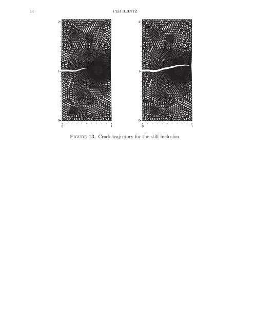
14 PER HEINTZ Figure 13. Crack trajectory for the stiff inclusion.
QUASI-STATIC CRACK GROWTH IN FRACTURE MECHANICS 15 6.3. Mixed mode conditions. The described strategy is applied to model the propagation of a crack initiated at the lower boundary of a beam, see Figure 14. The three holes disturb the stress/strain field and give rise to curvilinear crack trajectories. This problem has also been used by other researchers, see [1] and [2], who compared their computational results with experiments. The crack paths were found to be highly dependent on the position of the initial crack. Therefore two different initial configurations were selected for the two examples considered here. The plate is simply supported near the lower corners and subjected to a concentrated load at the center of the upper edge. As in example 1, the material parameters where set to E = 1 and ν = 0.3. A pointload P = (0, −1) was applied at the center of the upper boundary. Figure 14. Crack propagation trajectories for two different starting positions of the crack Figure 14 shows the crack trajectories for two different starting positions of the crack. The crack was initiated as a straight line cutting through five elemets before the simulation started. The trajectories shows similar results as in [2]. However, the material parameters in their paper was not presented.
- Page 1: FINITE ELEMENT CENTER PREPRINT 2005
- Page 4 and 5: On the numerical modeling of quasi-
- Page 6 and 7: 2 PER HEINTZ but seems to give the
- Page 8 and 9: 4 PER HEINTZ Figure 2. The cracktip
- Page 10 and 11: 6 PER HEINTZ Figure 4. Small FE mes
- Page 12 and 13: 8 PER HEINTZ 5.1.3. Evaluation of t
- Page 14 and 15: 10 PER HEINTZ 6. Numerical examples
- Page 16 and 17: 12 PER HEINTZ 14 12 analytic comput
- Page 20 and 21: 16 PER HEINTZ 7. Concluding remarks
- Page 23 and 24: QUASI-STATIC CRACK GROWTH IN FRACTU
- Page 25: 2004-12 Multi-adaptive Galerkin met
14 PER HEINTZ<br />
Figure 13. Crack trajectory for the stiff inclusion.


