Chalmers Finite Element Center - FEniCS Project
Chalmers Finite Element Center - FEniCS Project
Chalmers Finite Element Center - FEniCS Project

Create successful ePaper yourself
Turn your PDF publications into a flip-book with our unique Google optimized e-Paper software.
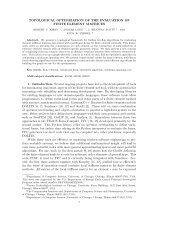
10 PER HEINTZ<br />
6. Numerical examples<br />
In this section we present three numerical examples that demonstrate the crack propagation<br />
algorithm, implemented as described in the previous sections. First, we consider<br />
a simple model problem of a single edged crack for which we compute and compare the<br />
energy release rate with the analytical value. Secondly, a weak and a stiff inclusion problem<br />
are considered. The final example demonstrates a more complicated loading case, taken<br />
from the litterature, where a simply supported beam is subjected to a pointload.<br />
In all examples, the parameter α is chosen such that the normal tractions are evaluated<br />
from the uncracked element ahead of the cracktip. The parameter δ must be chosen high<br />
enough to ensure stability of the method. In all examples δ was set to δ = C · (2µ + 3λ)<br />
where C depends on the approximation order of the basis functions. For linear triangles<br />
C = 2 was sufficient in all examples. If the material properties are different between the<br />
last cracked element and the element ahead of the cracktip, we simply use the highest value<br />
obtained from the two different materials. For an in depth discussion and mathematical<br />
proofs concerning the choice of the parameter δ see [6], [8] and references therein. The<br />
elastic properties are given in terms of Youngs modulus E and poissons ratio ν and we use<br />
the relations<br />
Eν<br />
(6.1)<br />
λ =<br />
(1 + ν)(1 − 2ν)<br />
Eν<br />
(6.2)<br />
λ =<br />
1 − ν 2<br />
E<br />
(6.3)<br />
µ =<br />
2(1 + ν)<br />
where (6.1) and (6.2) are for plane strain and plain stress problems respectivily.<br />
In example 2 and 3 we use a simple mesh refinement algorithm to increase the accuracy<br />
of the computed kink angle. The elements that are marked with indicator 1, see Figure<br />
7, are subdivided into four new triangles in two steps. Thus the original elements with<br />
indicator 1 are subdivided into 16 new triangles. Due to the properties of the refinement<br />
algorithm, the refinement is diffused through the grid such that no hanging nodes and no<br />
sharp corners are obtained.<br />
6.1. Single edged crack. Consider the single edged crack in Figure 9 subjected to a<br />
modus I load with n · σ · n = σ 0 = 1. The body is in plane stress and the elastic<br />
parameters are E = 1.0 Pa and ν = 0.3. The dimensions of the body are W = 1.0 m and<br />
h = 2.0 m. The stress intensity factor K I , representing the strength of the singularity at<br />
the cracktip, is now obtained from<br />
(6.4)<br />
K I = √ πa · f(a,W),<br />
where f(a,W) is a geometry factor. The relation between the stress intensity and the<br />
energy release rate is<br />
(6.5)<br />
J = K2 I<br />
E