Machine Manual - Production Tool Supply
Machine Manual - Production Tool Supply
Machine Manual - Production Tool Supply

You also want an ePaper? Increase the reach of your titles
YUMPU automatically turns print PDFs into web optimized ePapers that Google loves.
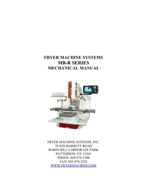
FRYER MACHINE SYSTEMS<br />
MB-R SERIES<br />
MECHANICAL MANUAL<br />
FRYER MACHINE SYSTEMS, INC.<br />
70 JON BARRETT ROAD<br />
ROBIN HILL CORPORATE PARK<br />
PATTERSON, NY 12563<br />
PHONE: 845-878-2500<br />
FAX: 845-878-2525<br />
WWW.FRYERMACHINE.COM
MECHANICAL DRAWINGS....................................................................................................................................................3<br />
HEAD ASSEMBLY..................................................................................................................................................................4<br />
Z AXIS COLUMN ....................................................................................................................................................................5<br />
Z AXIS RAM.............................................................................................................................................................................6<br />
X AXIS TABLE ........................................................................................................................................................................7<br />
X AXIS BALL SCREW ............................................................................................................................................................8<br />
Y AXIS SADDLE .....................................................................................................................................................................9<br />
Y AXIS BALL SCREW ..........................................................................................................................................................10<br />
TOOL CHANGER ..................................................................................................................................................................11<br />
BED AND COLUMN .............................................................................................................................................................12<br />
COUNTER WEIGHT..............................................................................................................................................................13<br />
RETENTION KNOBS ............................................................................................................................................................14<br />
maintenance MB R SERIES 2 OF 14
MECHANICAL DRAWINGS<br />
maintenance MB R SERIES 3 OF 14
HEAD ASSEMBLY<br />
maintenance MB R SERIES 4 OF 14
Z AXIS COLUMN<br />
maintenance MB R SERIES 5 OF 14
Z AXIS RAM<br />
maintenance MB R SERIES 6 OF 14
X AXIS TABLE<br />
maintenance MB R SERIES 7 OF 14
X AXIS BALL SCREW<br />
maintenance MB R SERIES 8 OF 14
Y AXIS SADDLE<br />
maintenance MB R SERIES 9 OF 14
Y AXIS BALL SCREW<br />
maintenance MB R SERIES 10 OF 14
TOOL CHANGER<br />
maintenance MB R SERIES 11 OF 14
BED AND COLUMN<br />
maintenance MB R SERIES 12 OF 14
COUNTER WEIGHT<br />
maintenance MB R SERIES 13 OF 14
FRYER PART NUMBERS<br />
CAT 40<br />
TOL-5450<br />
BT 40<br />
TOL-5456<br />
CAT 50<br />
TOL-5454<br />
NOTE:<br />
IF THRU COOLANT IS NEEDED, PLEASE CALL FOR PROPER<br />
PART NUMBER<br />
RETENTION KNOBS<br />
maintenance MB R SERIES 14 OF 14
FRYER MACHINE SYSTEMS<br />
ELECTRICAL &<br />
PROCEDURES MANUAL<br />
ANILAM 3000 CONTROL<br />
FRYER MACHINE SYSTEMS, INC.<br />
70 JON BARRETT ROAD<br />
ROBIN HILL CORPORATE PARK<br />
PATTERSON, NY 12563<br />
PHONE: 845-878-2500<br />
FAX: 845-878-2525<br />
WWW.FRYERMACHINE.COM<br />
Electrical manual 3000.doc 1 OF 38 4/30/07
SAFETY RULES.........................................................................................................................................................................3<br />
STARTUP PROCEDURE FOR FRYER MB SERIES MILLS..............................................................................................4<br />
UNPACK MACHINE.....................................................................................................................................................................4<br />
LINE VOLTAGE CHECK................................................................................................................................................................4<br />
MACHINE POWER-UP PROCEDURE ..............................................................................................................................................4<br />
VOLTAGE CHECKS (ALL VOLTAGES +/- 10%): ...........................................................................................................................5<br />
ADDITIONAL CHECKS:................................................................................................................................................................5<br />
STARTUP REPORT - ANILAM 3000 CONTROL.................................................................................................................6<br />
INITIAL START-UP QUALITY SURVEY.............................................................................................................................6<br />
MB-R SERIES ELECTRICAL DRAWINGS...........................................................................................................................8<br />
PANEL LAYOUT.....................................................................................................................................................................9<br />
3000 OPTIONS .......................................................................................................................................................................10<br />
3000 OPTIONS .......................................................................................................................................................................11<br />
3000 OPTIONS .......................................................................................................................................................................12<br />
MB Q SERIES ELECTRICAL DRAWINGS.........................................................................................................................13<br />
PANEL LAYOUT...................................................................................................................................................................14<br />
3000 OPTIONS .......................................................................................................................................................................16<br />
3000 OPTIONS .......................................................................................................................................................................17<br />
ANILAM ELECTRICAL DRAWINGS..................................................................................................................................18<br />
3000 CABLE LAYOUT..........................................................................................................................................................19<br />
CABINET WIRING DIAGRAM............................................................................................................................................20<br />
CONSOLE WIRING DIAGRAM...........................................................................................................................................21<br />
MB SERIES M CODES............................................................................................................................................................22<br />
MAINTENANCE SCHEDULE................................................................................................................................................23<br />
ADJUSTMENTS FOR ANILAM 3000 CONTROL ..............................................................................................................24<br />
SETUP AND TESTING..........................................................................................................................................................25<br />
YASKAWA GPD 315 SPINDLE DRIVE................................................................................................................................26<br />
-BALDOR VECTOR SPINDLE DRIVE PARAMETERS-....................................ERROR! BOOKMARK NOT DEFINED.<br />
INSTRUCTIONS FOR SETTING PARAMETERS...............................................ERROR! BOOKMARK NOT DEFINED.<br />
ANILAM 3000 SOFTWARE UPDATE INSTRUCTIONS ...................................................................................................29<br />
ANILAM 3000 SERVICE PROCEDURE FOR SAVING CONFIGURATION FILES.....................................................30<br />
RENISHAW TOOL PROBE INSTALLATION ..................................................................................................................................31<br />
DIAGNOSTICS OF ANILAM MB PLC.................................................................................................................................32<br />
ANILAM HARD DRIVE INSTALLATION ..........................................................................................................................33<br />
LOADING IPI FILE .................................................................................................................................................................35<br />
USER SETUP FOR ANILAM NETWORKING....................................................................................................................36<br />
FRYER OPTIONAL CHILLER INSTRUCTIONS...............................................................................................................38<br />
Electrical manual 3000.doc 2 OF 38 4/30/07
SAFETY RULES<br />
READ BEFORE OPERATING MACHINE<br />
1. PREVENT LOOSE CLOTHING, HAIR, JEWELRY FROM CONTACTING SPINDLE<br />
2. NEVER: CHANGE TOOLS, HANDLE SPINDLE, CHANGE PARTS OR PERFORM WORK<br />
ON MILL UNLESS CNC IS IN EMERGENCY STOP OR TOOL CHANGE MODES<br />
3. ALWAYS WEAR EYE PROTECTION WHEN OPERATING MILL.<br />
4. DO NOT OPERATE MILL WITHOUT AXIS MOTOR COVERS OR AXIS WAY COVERS IN<br />
PLACE.<br />
5. DO NOT PLACE OBJECTS OR HANDS BETWEEN COLUMN AND TABLE/SADDLE<br />
ASSY, UNLESS CNC IS IN EMERGENCY STOP POSITION.<br />
6. DO NOT MODIFY EQUIPMENT WITHOUT APPROVAL FROM FRYER MACHINE<br />
SYSTEMS. DOING SO MAY VOID YOUR WARRANTY.<br />
7. ELECTRICAL ENCLOSURES CONTAIN HIGH VOLTAGE. DISCONNECT EQUIPMENT<br />
FROM POWER SOURCE BEFORE OPENING CABINETS.<br />
8. CHECK LUBRICANT FILL LEVELS BEFORE OPERATING.<br />
9. DO NOT OPERATE POWER DRAWBAR UNIT WHILE SPINDLE IS IN MOTION.<br />
10. EMERGENCY STOP MILL WHEN NOT IN USE<br />
11. KEEP VISES, CLAMPS, FIXTURE OR WORKPIECE FROM EXTENDING BEYOND BACK<br />
EDGE OF TABLE.<br />
12. TURN OFF POWER IF:<br />
POWER PROBLEMS DEVELOP<br />
IN THE EVENT OF ELECTRICAL STORMS.<br />
AMBIENT TEMPERATURES EXCEED 105 DEGREES FARENHEIT.<br />
Electrical manual 3000.doc 3 OF 38 4/30/07
STARTUP PROCEDURE FOR FRYER MB SERIES MILLS<br />
WITH ANILAM 3000 MK CONTROLLERS<br />
Unpack <strong>Machine</strong><br />
1. Remove plastic wrap. Carefully inspect for any damage.<br />
2. Install leveling pads and level machine. (This is usually the responsibility of the rigger or customer)<br />
3. Remove Wooden counterweight SPIKE at top of machine.<br />
Assistance will be necessary to perform the following steps:<br />
4. Using a socket or suitable wrench (Pliers are not recommended) turn the Z<br />
ballscrew clockwise from the top of the screw enough to remove wooden shipping block on table. Be careful not<br />
to let the ratchet/wrench slip backwards.<br />
5. Turn the ratchet/wrench counter clockwise until counterweight chains are taut, and counterweight bar<br />
is free.<br />
6. Remove counterweight bar. At this time you must remove the ratchet/wrench otherwise serious damage could<br />
occur.<br />
7. Install the Z-Axis motor and drive belt, and any other items that may have been removed for shipping purposes.<br />
8. Check that front panel with swivel arm is clear of Z-Axis head motion.<br />
Line voltage check<br />
1. Verify 220/440vac. (+/- 10%) is wired to the main disconnect correctly.<br />
2. Verify 110vac plug is in a 20 amp minimum dedicated receptacle, or the warranty will be voided.<br />
3. The breaker for the 110vac must be a high magnetic breaker. An example is a Square D PN:Q0BHM-20<br />
4. Check all wire connections, relays, contacts and plugs to be sure nothing has become loose. If so, reseat or<br />
tighten before turning on main power.<br />
5. All voltage checks should be recorded on the STARTUP REPORT form.<br />
<strong>Machine</strong> power-up procedure<br />
1. The electrical cabinet door should remain open until this startup is completed. The switch on the back of the<br />
console (MANUAL/AUTO) should be in the AUTO position.<br />
2. Turn on the main disconnect switch on the electrical cabinet to power up 220/440vac. A pair of pliers may be<br />
used to turn the disconnect rod ¼ turn CW.<br />
3. On the side of the electrical cabinet, the switch marked CONTROL POWER (0/1) should be in the 1 position to<br />
power up 110vac.<br />
4. Press F10 to continue, press ENTER to boot into software.<br />
5. Rotate the E-stop button CW, then press SERVO RESET to engage servo drives.<br />
Electrical manual 3000.doc 4 OF 38 4/30/07
Voltage checks (All voltages +/- 10%):<br />
1. Check for +160VDC at the large blue capacitor in the electrical cabinet.<br />
2. Check for 110VAC at the Corcom EMI line filter in the electrical cabinet.<br />
3. Check for +5VDC between pins 1 & 4 (common) on the P2 connector of the power supply in the console.<br />
4. Check for +12VDC between pins 8 & 4 (common) on the P2 connector of the power supply in the console.<br />
5. Check for –12VDC between pins 11 & 4 (common) on the P2 connector of the power supply in the console.<br />
6. Check for +5VDC between pins 1 & 3 (common) on the P2 connector of the power supply in the electrical<br />
cabinet. Refer to the Panel Layout drawing for more detail.<br />
7. Check for +15VDC between pins 6 & 3 (common) on the P2 connector of the power supply in the electrical<br />
cabinet. Refer to the Panel Layout drawing for more detail.<br />
8. Check for –15VDC between pins 5 & 3 (common) on the P2 connector of the power supply in the electrical<br />
cabinet. Refer to the Panel Layout drawing for more detail.<br />
9. Check for +24VDC at the 24volt power supply (blue & yellow wires). Refer to the Panel Layout drawing for<br />
more detail.<br />
Additional Checks:<br />
1. Make sure way surfaces are receiving sufficient oil from pump.<br />
2. Make sure air pressure to power drawbar unit (if so equipped) is set at 85psi minimum.<br />
All information should be recorded on a Fryer <strong>Machine</strong> Startup Form with any unusual conditions<br />
listed and returned to Fryer <strong>Machine</strong> Service Dept. If any problems are encountered or if you<br />
have any questions, please contact FRYER MACHINE SYSTEMS Service Department at (845)<br />
878-2500.<br />
Electrical manual 3000.doc 5 OF 38 4/30/07
STARTUP REPORT - ANILAM 3000 Control<br />
CUSTOMER: ____________________________________________DATE:____________________<br />
MODEL #: ____________________ SERIAL #: _________________ CONTROL SN#: ____________________<br />
DISTRIBUTOR: _______________________________ SERVICE TECH: _________________________________<br />
SHOPCONTACT:___________________________TITLE:__________________________________<br />
ATTENTION:<br />
ITEMS CAN BECOME LOOSE DURING SHIPPING CAUSING A LOSS OF CONNECTIONS. THIS MAY RESULT IN<br />
IMPROPER MACHINE FUNCTION AND/OR DAMAGE TO THE MACHINE OR COMPONENTS. BEFORE INITIAL<br />
POWER-UP:<br />
• TIGHTEN ALL SCREWS AND ELECTRICAL CONNECTIONS IN THE ELECTRICAL CABINET .<br />
• CHECK TO ENSURE THAT ALL ELECTRICAL COMPONENTS ARE PROPERLY SEATED AND SECURED.<br />
70 Jon Barrett Road<br />
Robin Hill Corporate Park<br />
Patterson, N.Y. 12563<br />
Phone: (845) 878-2500<br />
Fax: (845) 878-2525<br />
E-mail: service@fryermachine.com<br />
ELECTRICAL CONNECTIONS AND COMPONENTS CHECKED: _________<br />
COMPUTER POWER SUPPLY (+5, +/- 12 VDC) (in consol)<br />
SERVO POWER SUPPLY (+5, +/-15 VDC)<br />
+5 VDC: ________ P2-1 +5 VDC: ___________ P2-1<br />
+12 VDC: ________ P2-8 +15 VDC: ___________ P2-6<br />
• -12 VDC: ________ P2-11 -15 VDC: ___________ P2-5<br />
(COMMON P2-4)<br />
(COMMON P2-3)<br />
24VDC POWER SUPPLY- 24VDC: ________<br />
220/440 VAC (MAIN DISCONNECT)<br />
L1-L2 _________ L2-L3 _________ L1-L3 _________ L1-GND _________ L2-GND _________ L3-GND _________<br />
110 VAC (CORCOM LINE FILTER) 110VAC _________ 160 VDC (DRIVE BUS CAPACITOR) 160VDC_________<br />
WAYLUBE: PRESENT AT X, Y & Z BOX WAY SURFACES: __________<br />
AIR PRESSURE: _________PSI<br />
HOUR METER READING ______________<br />
INITIAL START-UP QUALITY SURVEY<br />
At Fryer <strong>Machine</strong> Systems, we strive to continuously improve the quality of our products and services.<br />
As a qualified machine tool technician, your feedback is an essential part of this ongoing process.<br />
Please take a moment to fill out the following information. It will be greatly appreciated.<br />
Please circle the appropriate response (1=worst, 5=best) for each question. Feel free to add any comments.<br />
INITIAL IMPRESSIONS<br />
Was machine received in satisfactory condition? ................................................................Yes No<br />
If no, what was lacking?<br />
____________________________________________________________________________<br />
Electrical manual 3000.doc 6 OF 38 4/30/07
MACHINE SERIAL NO.______________________<br />
DATE ____________<br />
Please rate the overall appearance of the machine: ...........................................................1 2 3 4 5<br />
Comments:<br />
____________________________________________________________________________<br />
____________________________________________________________________________<br />
PERFORMANCE<br />
Please rate the mechanical systems of the machine: ..........................................................1 2 3 4 5<br />
____________________________________________________________________________<br />
____________________________________________________________________________<br />
Please rate the electrical systems of the machine: ..............................................................1 2 3 4 5<br />
Comments:<br />
____________________________________________________________________________<br />
____________________________________________________________________________<br />
SERVICE<br />
Were there any problems with the machine during start-up? ...............................................Yes No<br />
If yes, please list:<br />
____________________________________________________________________________<br />
____________________________________________________________________________<br />
____________________________________________________________________________<br />
What issues, if any, are still outstanding?<br />
____________________________________________________________________________<br />
____________________________________________________________________________<br />
____________________________________________________________________________<br />
Was our Service Dept. helpful during the start-up? Please rate us:.....................................1 2 3 4 5<br />
GENERAL<br />
Would you recommend this machine to others?................................................................... Yes No<br />
Why?<br />
____________________________________________________________________________<br />
____________________________________________________________________________<br />
____________________________________________________________________________<br />
ADDITIONAL COMMENTS:<br />
________________________________________________________________________<br />
________________________________________________________________________<br />
________________________________________________________________________<br />
Electrical manual 3000.doc 7 OF 38 4/30/07
MB-R SERIES ELECTRICAL DRAWINGS<br />
Electrical manual 3000.doc 8 OF 38 4/30/07
PANEL LAYOUT<br />
Electrical manual 3000.doc 9 OF 38 4/30/07
Ω−<br />
3000 OPTIONS<br />
Electrical manual 3000.doc 10 OF 38 4/30/07
3000 OPTIONS<br />
Electrical manual 3000.doc 11 OF 38 4/30/07
3000 OPTIONS<br />
Electrical manual 3000.doc 12 OF 38 4/30/07
MB Q SERIES ELECTRICAL DRAWINGS<br />
Electrical manual 3000.doc 13 OF 38 4/30/07
PANEL LAYOUT<br />
Electrical manual 3000.doc 14 OF 38 4/30/07
FRYER MB PART LIST<br />
DRAWING REF. – PANEL LAYOUT<br />
SERIES B<br />
ITEM PART NO. PART NAME QTY SPECIFICATION<br />
1 DRV-1010 SPINDLE DRIVE 1<br />
2 CMB-2320 SERVO CONTROL BOARD 1<br />
3 MSE-1930 24VDC POWER SUPPLY 1<br />
4 MSE-1950 5/15VDC POWER SUPPLY 1<br />
5 DRV-1185 SERVO DRIVE BOARD 3<br />
6 SWT-5190 DISCONECT SWITCH 1<br />
7 MSE-1016 CORCOM FILTER 1<br />
8 MSE-1185 OMRON RELAY 24VDC 2<br />
9 MSE-1954 BRIDGE RECTIFIER 1<br />
MISC. ITEMS NOT IN DRAWING<br />
SCA-1010 COUPLED QUILL SCALE 1<br />
SWT-5014 MICRO SWITCH 4<br />
MSE-1460 AIR FILTER 1<br />
MTR-3050 AXIS MOTOR W/ CABLE 3<br />
SWT-5180 OVERRIDE SWITCH 2<br />
SWT-5200 E-STOP BUTTON 1<br />
SWT-5170 E-STOP BLOCK 1<br />
CMB-2168 FLOPPY DRIVE 1<br />
CMD-2164 HARD DRIVE (PART STORAGE) 1<br />
CMB-2290 F-KEY STRIP 1<br />
CMB-2280 MAIN KEY BOARD (3000 CONTROL) 1<br />
CMB-2286 MAIN KEY BOARD (5000 CONTROL) 1<br />
Electrical manual 3000.doc 15 OF 38 4/30/07
3000 OPTIONS<br />
Electrical manual 3000.doc 16 OF 38 4/30/07
3000 OPTIONS<br />
Electrical manual 3000.doc 17 OF 38 4/30/07
ANILAM ELECTRICAL DRAWINGS<br />
Electrical manual 3000.doc 18 OF 38 4/30/07
DWG REF.#302008516<br />
3000 CABLE LAYOUT<br />
Electrical manual 3000.doc 19 OF 38 4/30/07
DWG REF.#302008517<br />
CABINET WIRING DIAGRAM<br />
Electrical manual 3000.doc 20 OF 38 4/30/07
DWG REF. #D000775<br />
CONSOLE WIRING DIAGRAM<br />
Electrical manual 3000.doc 21 OF 38 4/30/07
MB SERIES M CODES<br />
M00 Program stop<br />
M01 Optional stop(Optional hardware is required)<br />
M02 End of program and rewind<br />
M03 Spindle clockwise (an “s” code must also be present to specify RPM)<br />
M04 Spindle counter-clockwise (an “s” code must also be present to specify RPM)<br />
M05 Spindle stop<br />
M06 Turn off spindle and does tool change( a “T” number must be present to specify tool requested)<br />
M07 Mist coolant on(optional)<br />
M08 Flood coolant on(optional)<br />
M09 Mist and flood coolant off<br />
M10 Optional indexer interface, will cause cycle start on indexer and wait for finish pulse<br />
M11 Spare “M” function turns on output bit 0<br />
M12 Spare “M” function turns off output bit 0<br />
M9293x1 will display following error on screen<br />
ATC M-CODES<br />
M12<br />
M13<br />
M14<br />
M15<br />
M16<br />
M50<br />
M51<br />
M52<br />
M53<br />
M54<br />
M55<br />
M58<br />
M59<br />
M61<br />
MISC MCODE OFF (CHIP AUGER OR BRAKE ETC)<br />
U BRAKE ON<br />
U BRAKE OFF<br />
W BRAKE ON<br />
W BRAKE OFF<br />
SPINDLE ORIENT<br />
ORIENT OFF<br />
ATC CAROUSEL IN<br />
ATC CAROUSEL OUT<br />
DRAWEAR ON<br />
DRAWEAR OFF<br />
ATC INDEX FWD<br />
ATC INDEX REV<br />
HOME ATC<br />
Electrical manual 3000.doc 22 OF 38 4/30/07
MAINTENANCE SCHEDULE<br />
FRYER MB SERIES MILLING MACHINES<br />
fill oil cups 1<br />
fill lube pump 2<br />
fill drawbar lube 3<br />
grease head 4<br />
grease drawbar 5<br />
check coolant level<br />
change coolant 6<br />
check head tram<br />
check machine level<br />
check gibs<br />
check backlash<br />
check belt tension<br />
daily weekly monthly 3 months 6 months yearly as req’d.<br />
X<br />
check servo cabinet<br />
and console fans,<br />
clean filters<br />
replace servo cabinet<br />
and console filters 7 X<br />
X<br />
X<br />
X<br />
X<br />
X<br />
X<br />
X<br />
X<br />
X<br />
X<br />
X<br />
X<br />
1 -Mobil Velocite #10 (ISO VG 22) or equivalent<br />
2 -Mobil Vactra #2 (ISO 68) or equivalent<br />
3 -Break-Free Synthetic Air <strong>Tool</strong> Oil (5W) or equivalent<br />
4 -Mobil 1 Universal Synthetic Grease (ISO VG 220) or equivalent<br />
5 -Mobil XHP 220 Special Moly Grease or equivalent<br />
6 -Valenite Turn Tech Blue Metalworking Fluid or equivalent<br />
7 -See Anilam <strong>Manual</strong><br />
Electrical manual 3000.doc 23 OF 38 4/30/07
ADJUSTMENTS FOR ANILAM 3000 CONTROL<br />
FOR MB MACHINES<br />
PART 1<br />
GLENTEK SMA 7215-2 DRIVE CARD PRESETS<br />
1. E-stop machine in the middle of its travel X-Y-Z. Make sure parameters for DSP motion are as follows:<br />
DSP Motion Gain Tables:<br />
(All axis)<br />
FEED RAPID NO MOTION<br />
Kp 10 7 10<br />
Ki 0 0 5<br />
Kd 10 10 10<br />
Kf 0 0 0<br />
Il 0 0 10<br />
Ds 5 2 5<br />
2. Turn power off.<br />
3. Disconnect the J1 connector on all drive cards.<br />
4. Set DVM to thousand OHMs scale. Connect black lead to the J2-1 common test lead on drive card. This<br />
is the common to set all potentiometers.<br />
5. Adjust as follows: (NOTE: Look at diagram on side of drive card for correct position)<br />
TEST POINT ADJUST POTOTENTIOMETER OHM VALUE<br />
J2-1 (Common)<br />
J2-2 (Signal Input)<br />
J2-3 (Tach Input)<br />
J2-4 (Diff Sig Gain) (1) Diff Gain 0 or Full CCW<br />
J2-5 (Signal Gain) (2) Sig Gain 2.18K<br />
J2-6 (Tach Gain) (4) Tach 4.60K<br />
J2-7 (Comp) (5) Comp 3.40K<br />
(6) Fldbk Full CW (20 turn pot)<br />
(7) ILIM Full CW (20 turn pot)<br />
LOOP GAIN<br />
Full CW ( 1 turn pot)<br />
6. For your reference, DIP switch settings should be:<br />
ON (Towards circuit board) 1-5-6-7-9<br />
OFF(Away form circuit board) 2-3-4-8-10<br />
7. Reconnect all J1 connectors.<br />
Electrical manual 3000.doc 24 OF 38 4/30/07
PART II ADJUSTMENTS FOR ANILAM 3000/5000 CONTROL ON MB MACHINES – MOTION<br />
SETUP AND TESTING<br />
8. Once the drives are pre-adjusted, turn on power to machine, make sure all axis are in the middle of their<br />
travel. Go to machine setup and disable home requirement.<br />
9. Go to motion setup and testing.<br />
10. Leave drives off.<br />
11. Press axis you wish to test (X or Y or Z).<br />
12. Press balance, this will cause the DSP board to output 0 mV and START.<br />
13. Inside the CRT box is the DSP board. Set your DVM to mV scale, connect the black lead to the Glentek<br />
drive card you are setting at the J2-1 test point (common) and the red lead to J2-2 test point (Signal<br />
Input). Adjust the appropriate POT on the DSP board (labeled on card) to obtain 0 mV.<br />
14. Now you can remove the DVM leads. Press manual and then turn on the drives , then go to balance. On<br />
the screen under the “X-Y-Z” readout is an “F”. Adjust the balance POT (3) on the Glentek drive card for 0<br />
feed rate. This will stop the axis from drifting.<br />
15. Now press manual to cancel the balance test.<br />
16. Press signal gain to activate the signal gain test. It will ask for a time period = 2, and press start. This will<br />
cause the control to output .9 VDC and the axis will move positive and negative.<br />
17. Adjust the signal gain POT on the appropriate Glentek drive card to obtain 10% of the rapid feed rate<br />
(usually 20 IPM).<br />
18. Press manual and you are done with the test. Repeat steps 11 through 18 until all axis are adjusted.<br />
Electrical manual 3000.doc 25 OF 38 4/30/07
YASKAWA GPD 315 SPINDLE DRIVE<br />
PARAMETERS FOR MILLS<br />
TO RUN MACHINE IN LOCAL MODE:<br />
1. Turn servos on.<br />
2. Make sure the spindle is off<br />
3. The run light should be blinking on the PC7 drive<br />
4. Press the “ DSPL “ key 5 times so the “ LO/RE “ is illuminated in red.<br />
5. Use the “ ∧ ” or “ ∨ ” arrow buttons to display “ Lo “<br />
6. Press the “DSPL “ key to illuminate “F/R”, use the “ ∧ ” or “ ∨ ” arrows to select forward or reverse spindle rotation.<br />
7. Press the “ DSPL “ key to illuminate “FREF”<br />
8. Press the “RUN” button and adjust the min/max knob to desired frequency (RPM)<br />
PROCEDURE TO PROGRAM PC7 PARAMETERS:<br />
1. Turn the drives on<br />
2. Make sure the spindle is off<br />
3. The run light should be blinking on the PC7 drive<br />
4. Press the “ DSPL “ key 6 times until “PRGM” is illuminated in red<br />
5. Use the “ ∧ ” or “ ∨ ” arrow buttons to select the parameter that must be edited<br />
6. Press “ DATA/ENTER “ key to view the value of the parameter<br />
7. This parameter can now be changed with the “ ∧ ” or “ ∨ ” arrow buttons<br />
8. Once the change has been made press the “ DATA/ENTER “ key. The display will change to display the parameter<br />
number (ex. “ N001 “ )<br />
9. Repeat this procedure for all parameters that must be modified.<br />
TO INITIALIZE ALL PARAMETERS: (Warning this will reset all parameters in the PC7)<br />
1. Follow the above procedure to set parameter N001=10<br />
2. Once N001 is set recheck the value it should equal 1, this confirms that all parameters have been reset to factory default<br />
3. Change the parameters specified below: (Warning do not change any other values!)<br />
N001=4<br />
N002=1 (Vector control mode)<br />
N011=Depends on the machine. Standard machines settings MB15=150 , MB14=121<br />
This sets the maximum frequency to limit the RPM of the machine. To accurately set this:<br />
Follow the procedure above to run the machine in Local mode.<br />
Press the “ DSPL “ button once to move the green light to “ FOUT “<br />
Adjust the Min/Max knob to make the display reads 60 HZ ±.5<br />
Use a tachometer and record the RPM<br />
Use this formula to calculate the RPM / HZ= recorded rpm / 60 HZ<br />
Now divide the maximum RPM desired by the RPM/HZ this is the value that should be entered for N011.<br />
N019=3 (Accel time may have to be increased if fault occurs during accel to max speed.)<br />
N020=3 (Decel time may have to be increased if fault occurs during decel from max speed to stop)<br />
N022=2 (Emergency stop decel time)<br />
N036=(motor rated current-read motor tag) MB15/16=20 MB11/14=14 *440 VAC use ½ values<br />
N037=1<br />
N052=19<br />
N058=3 ( ZERO SPEED )<br />
NO59=1 (DURING RUNNING)<br />
N092=1<br />
N096=2<br />
N106=2.7<br />
N107=( 220VAC=.235) (440VAC= .924)<br />
N110=(MB15/16=59) (MB11/14=39)<br />
4. When complete make sure unit is in “rE” (remote mode) press “DSPL” until “FREF”is illuminated.<br />
Dip switch settings: SW1=NPN SW2= 1=off 2=off<br />
Refer to manual for any further information.<br />
Electrical manual 3000.doc 26 OF 38 4/30/07
BALDOR H2 VECTOR SPINDLE DRIVE PARAMETERS<br />
MB-10<br />
Instructions for setting parameters and tuning drive.<br />
1. Make sure the software version is 1.06 or newer. If it is not update to the latest software version.<br />
2. Make sure motor is securely bolted down, as the auto tuning will cause the motor to rotate.<br />
3. In order to set the parameters press the program button, use the up-down arrow keys to cursor to the correct parameter<br />
level. Once the correct parameter is selected press enter this will enter into this parameter. Use the right arrow key to<br />
go to the next parameter. Press enter to modify the parameter, use the left and right arrow key to select the digit and<br />
the up and down key to change the value. Once the correct value is displayed press enter to save the change. Press<br />
status to exit the parameter edit field.<br />
4. Set the following parameters:<br />
LEVEL 2 BLOCKS →DRIVE CONFIGURE →FACTORY SETTINGS=1-YES<br />
LEVEL 2 BLOCKS→DRIVE CONFIGURE→SPEED UNITS=1-RPM<br />
LEVEL 2 BLOCKS→DRIVE CONFIGURE→POWER INPUT=2-THREE PHASE<br />
(Note: use single phase only if ordered.)<br />
=0-SINGLE PHASE<br />
LEVEL 2 BLOCKS →DRIVE PROTECT→OVERLOAD=0-FAULT<br />
LEVEL 2 BLOCKS→MISCELLANEOUS→HOMING SPEED=200RPM.<br />
SPEEDS 2-15=0<br />
LEVEL 2 BLOCKS→MISCELLANEOUS→HOMING OFFSET=1024 (Note: change this value to adjust spindle orient<br />
position)<br />
LEVEL 2 BLOCKS→MOTOR CONTROL→CONTROL TYPE=2-CLOSED VECTOR<br />
LEVEL 2 BLOCKS→MOTOR DATA→MOTOR RATED VOLT=220(see motor tag)<br />
LEVEL 2 BLOCKS→MOTOR DATA→MOTOR RATED AMP=22(see motor tag)<br />
LEVEL 2 BLOCKS→MOTOR DATA→MOTOR RATED SPEED=1750(see motor tag)<br />
LEVEL 2 BLOCKS→MOTOR DATA→MOTOR RATED FREQ=60(see motor tag)<br />
LEVEL 2 BLOCKS→MOTOR DATA→ENCODER COUNTS=1024(see encoder)<br />
LEVEL 2 BLOCKS→BRAKE ADJUST→RESISTOR OHMS=15(check resistor)<br />
LEVEL 2 BLOCKS→BRAKE ADJUST→RESISTOR WATTS=1000(check resistor)<br />
LEVEL 1 BLOCKS→INPUT SETUP→OPERATING MODE=14-BIPOLAR<br />
LEVEL 1 BLOCKS→INPUT SETUP→COMMAND SOURCE=2-ANALOG IN2<br />
LEVEL 1 BLOCKS→OUTPUT SETUP→DIGITAL OUTPUT1=8-AT ZERO SPEED<br />
LEVEL 1 BLOCKS→OUTPUT SETUP→DIGITAL OUTPUT2=25-AT POSITION<br />
LEVEL 1 BLOCKS→OUTPUT SETUP→RELAY OUTPUT1=17-FAULT<br />
LEVEL 1 BLOCKS→OUTPUT SETUP→ZERO SPEED SET POINT=50<br />
LEVEL 1 BLOCKS→PRESET SPEED 1=200RPM<br />
LEVEL 1 BLOCKS→RAMP RATES→ACCEL TIME 1=5 SEC<br />
LEVEL 1 BLOCKS→RAMP RATES→DECEL TIME 1=7 SEC<br />
5. Once these values are set enable the drive by either commanding a M50 on the Anilam control or placing a jumper<br />
wire on the Baldor terminal strip between J2-8 and J3-21. Then put the drive in local mode.<br />
LEVEL 2 BLOCKS→AUTOTUNE→ONE STEP TUNING=1-YES. Follow the directions on the BALDOR screen. This will go through the auto<br />
tuning procedure which will run the motor and set parameters automatically.<br />
6. Once the auto tuning is complete set :<br />
LEVEL 2 BLOCKS→DRIVE LIMITS→MAXIMUM OUTPUT SPEED=6000 ( if this requires a higher spindle<br />
speed change this parameter)<br />
7. Remove temporary jumper and put drive in remote mode, install all covers.<br />
Electrical manual 3000.doc 27 OF 38 4/30/07
NOTES<br />
NOTE 1: The drive must be programmed for maximum RPM through the control. Cycle the drive forward and reverse<br />
allowing the spindle to obtain the extreme RPM ranges, if an error occurs during accel or decel the appropriate value should be<br />
enlarged.<br />
NOTE 2: The homing offset (LEVEL 2 BLOCKS→MISCELLANEOUS→HOMING OFFSET) is used only on machines<br />
equipped with Automatic <strong>Tool</strong> Changers. This will be adjusted from its original factory set value of 1024. After doing an<br />
M50 (orient spindle) command, adjust accordingly to correct the spindle home position.<br />
NOTE 3: Auto-tune values are set by following the instructions above. No manual entry is required.<br />
Electrical manual 3000.doc 28 OF 38 4/30/07
Anilam 3000 software update instructions<br />
1. Press E-stop and plug in an external keyboard<br />
2. Press F10 exit<br />
3. Press clear then type password “Z48” ↵ (enter)<br />
4. Now you are in DOS at the C:\P3M prompt *<br />
5. Type “cd..” ↵ You will now be in the root directory c:\<br />
6. Type “md old”↵ This will create an old directory<br />
7. Type “cd P3M” (*) This will return you to the P3M directory<br />
8. Type “copy *.* c:\old”↵ This will copy all files to the old directory for backup purposes. If there is a<br />
problem with the software installation you can get your machine back to original operating software<br />
by copying all the files in the old directory back to the P3M directory. To do this type “cd..”↵ - “cd<br />
old” - “copy *.* c:\P3M” say yes to overwrite files. Power down to restore when completed copying<br />
files.<br />
9. Now you can install the software update disk . (If you received the software via E-mail please copy<br />
all attached files to a clean 3.5” disk ) Type “a:”↵<br />
10. Type “install”↵ this will start the installation process follow the directions on the screen.<br />
11. Once you have completed the installation process and your machine is functioning properly you must<br />
backup your configuration file onto the floppy disk in the electrical cabinet (usually mounted on the<br />
door). See the Anilam manual for directions.<br />
* When updating a 5000 control the directory is c:\P5M<br />
Electrical manual 3000.doc 29 OF 38 4/30/07
ANILAM 3000 Service Procedure for Saving Configuration files.<br />
Copy Configuration<br />
This feature enables the user to make copies of the configuration and save the copies to a floppy<br />
diskette.<br />
NOTE: FRYER MACHINE recommends that you copy your Configuration file before any changes<br />
are made to the system. Such as, software updates, backlash adjustments, console swap etc. (↵<br />
= ENTER)<br />
1. Go to the Software Options Menu.<br />
2. #2 Setup Utility ↵<br />
3. #3 Utilities ↵<br />
4. #2 Copy Configuration ↵<br />
5. Enter the password Z48 ↵<br />
6. Highlight A: to copy the configuration to a floppy diskette. The configuration will be saved as<br />
A:\P3MCFG.CFG ( 3000 ) OR A:\P5MCFG.CFG ( 5300 )<br />
Restore from Copy<br />
Use this feature to restore a copy of the configuration from the A drive (A:\P3MCFG.CFG) and<br />
save it as the new configuration file.<br />
NOTE: If you restore your configuration file from a copy or a backup you will need to reboot when<br />
the system prompts to do so. You will prompt for an automatic reboot.<br />
1. Go to the software Options Menu.<br />
2. #2 Setup Utility ↵<br />
3. #3 Utility ↵<br />
4. #3 Restore From Copy ↵<br />
5. Enter the password Z48 ↵<br />
6. Highlight A: to restore the configuration from a floppy diskette. The configuration will be<br />
restored from A:\P3MCFG.CFG ( 3000 ) OR A:\P5MCFG.CFG ( 5300 )<br />
Print configuration<br />
Use this feature to save a copy of the configuration to diskette as a text file. P3CFG.TXT ( 3000 )<br />
OR P5CFG.TXT ( 5300 ) may then be taken to desktop P.C. and printed as a readable text file.<br />
1. Go to the Software Options Menu.<br />
2. #2 Setup Utility ↵<br />
3. #3 Utility ↵<br />
4. #6 Printer Configuration ↵<br />
5. #2 Text File (A:) ↵<br />
6. F1 Yes Print Anilam 3000 M/MK CNC VER.XXX to A:\P3MCFG.TXT? OR 5300 M/MK CNC<br />
VER. XXX TO A:\ P5MCFG.TXT?<br />
Electrical manual 3000.doc 30 OF 38 4/30/07
Renishaw <strong>Tool</strong> Probe Installation<br />
This will assist you in setting up and installing your Renishaw TS-27R tool probe on your Fryer milling machine with Anilam<br />
control. Make sure you read the instruction manual that came with the Renishaw probe and the Anilam manual pertaining to<br />
probing cycles.<br />
The probe has been pre-wired and tested on the Fryer machine at the factory. The manuals also can be downloaded in PDF<br />
format from either Renishaw.com or Anilam.com Installation should be completed at the customer’s facility. Follow these<br />
basic instructions referring to the manufacturers manuals for further details:<br />
1. Find a suitable mounting location for the probe ( most common is the far right hand corner of the table ) The probe<br />
should be mounted with the stylus pointing up and towards the left, this will exit the cable to the right. The Stylus<br />
should be approximately ½ the largest tool diameter used from the positive limit in x axis and at the rearmost t-slot(as<br />
long as it is a couple inches from the y limit). A t-nut can be used to mount the probe base with a ½-13 socket head<br />
cap screw. Make sure the cable will not interfere with anything during machine operation.<br />
2. Once the probe is securely mounted tram the probe within .0002” perpendicular and parallel to the machine slides.<br />
See Renishaw installation manual for further details.<br />
3. Follow the Anilam instructions to set the parameters according to your installation.<br />
4. Now you will need a tool with a known diameter to preset the tool presetter. You should use the Anilam G150 or tool<br />
probe calibration cycle. See the Anilam manual for further details.<br />
5. Once the G150 cycle is accomplished a G53 fixture offset should be activated and set to the top of the part so that all<br />
other tool to be set with the G151 cycle will be referenced to the top of the part.<br />
Electrical manual 3000.doc 31 OF 38 4/30/07
Diagnostics of Anilam MB PLC<br />
Refer to the Anilam <strong>Manual</strong>-Integral Programmable Intelligence User’s Guide for more information, included is the<br />
page on “Viewing the IPI Monitor” for your reference.<br />
An example of the input and output bits:<br />
Can 0 input bit 0<br />
Can 0 input bit 1<br />
Can 0 input bit 2<br />
Can 0 input bit 3<br />
Can 0 input bit 4<br />
Can 0 input bit 6<br />
Can 0 input bit 7<br />
Can 0 input bit 8<br />
Can 0 output bit 0<br />
Can 0 output bit 1<br />
Can 0 output bit 2<br />
Can 0 output bit 3<br />
Can 0 output bit 4<br />
Can 0 output bit 5<br />
Can 1 input bit 0<br />
Can 1 input bit 1<br />
Can 1 input bit 2<br />
Can 1 input bit 3<br />
Can 1 input bit 4<br />
Can 1 input bit 5<br />
Can 1 input bit 6<br />
Can 1 input bit 7<br />
X axis Home Switch 0=on trip dog 1=off trip dog (nc switch)<br />
Spindle drive fault 0=drive ok 1=spindle drive fault<br />
Y axis Home Switch 0= on trip dog 1=off trip dog (nc switch)<br />
Low Way Lube 0=low lube level 1=good oil level (no float switch)<br />
Z axis Home Switch 0=on trip dog 1=off trip dog (nc switch)<br />
Index complete cycle<br />
Spindle zero speed 0=spindle on 1=spindle not running<br />
Spindle in orient position 0=not orient 1=spindle in orient position<br />
Spare M-code M11=on M12=off<br />
Indexer start command (enables wait state)<br />
Mist coolant 1=on M7 0=off M9<br />
Spindle Enable 1=run the spindle or orient (power to spindle motor)<br />
Spindle Orient 1=orient the spindle for tool changeM50 0=off M51<br />
Flood coolant 0=off M9 1=on M8<br />
Drawbar off switch 0=tool not clamped 1=tool clamped (no sw on dbar air cyl)<br />
Drawbar on switch 0=tool locked 1=tool released (no switch on dbar air cyl)<br />
Low air pressure switch 0=low air pressure 1=good air pressure (no switch)<br />
ATC carousel in under spindle 0=not in 1=under spindle (no prox switch)<br />
ATC carousel out 0=not out 1=normal position (no prox switch)<br />
ATC Geneva drive prox 0=at pocket 1=not at pocket (no prox switch)<br />
ATC home prox 0=not at home pocket 1=at pocket 1 (no prox switch)<br />
<strong>Manual</strong> <strong>Tool</strong> in/out button on head 0=not pressed 1=pressed(no momentary sw)<br />
Can 1 output bit 0<br />
Can 1 output bit 1<br />
Can 1 output bit 3<br />
Can 1 output bit 4<br />
ATC index direction<br />
ATC index 1=spin the ATC geneva drive motor M58 or M59<br />
ATC carousel in under head M52=1 move under head 0=retract M53<br />
Drawbar on 1=drawbar on to release the tool (also airblast on)M54=off M55<br />
Electrical manual 3000.doc 32 OF 38 4/30/07
MATERIALS REQUIRED:<br />
-Hard Drive<br />
-<strong>Machine</strong> Parameter Disk<br />
-Blank, Formatted 3.5” Floppy Disk<br />
ANILAM HARD DRIVE INSTALLATION<br />
PROCEDURE:<br />
1. Install the hard drive into the control. Depending on the machine model, the hard drive will be located<br />
either in the operator console or the computer chassis in the electrical cabinet.<br />
2. If you received a DSP and/or keyboard chip with your new software, please install it following the<br />
directions provided with the chip(s).<br />
3. Plug a standard keyboard into the control. Start the computer. If the computer boots into the Anilam<br />
software, proceed to Step 3. Otherwise, proceed as follows: During the initial boot sequence, enter the<br />
BIOS setup menu by pressing the key specified by the message “press __ to enter setup” (usually or<br />
). You will need to enter the “Main” or “Standard CMOS Setup” menu. Now you must auto-detect<br />
the hard drive. Due to variations in the BIOS versions used by Anilam, it is difficult to provide one exact<br />
procedure to cover all controls. Call for assistance if you run into any problems. NOTE: For non-Pentium<br />
computers using large hard drives, check the auto-detected information for “no. of heads”. If this field<br />
says 16, it needs to be changed to 15. Highlight the field with the cursor and use the minus key to<br />
change. Now proceed to the “Exit” menu. Choose “Save changes and exit”- if prompted, answer “Y”<br />
.<br />
4. The computer should reboot and start the Anilam software. Press until you get to the Software<br />
Options menu. Press +. When prompted for the password, type the password corresponding to<br />
your control from the list below, followed by .<br />
-“Y10” for 1100 controls<br />
-“SERVICE” for 1400 controls<br />
-“Z48” for 3X00 5X00 controls<br />
5. You should see a black screen with the DOS prompt:<br />
-S1100\> for 1100 controls<br />
-S1400\> for 1400 controls<br />
-P3M\> for 3X00 controls<br />
-P5M\> for 5X00 controls<br />
6. Insert the machine’s original parameter disk into the floppy drive.<br />
7. Type “cd\” . Then, type “A:” . Then, type:<br />
“COPY *.* C:\_____” , inserting the directory name that corresponds to your control from the list<br />
below:<br />
S1100 for 1100 controls<br />
S1400 for 1400 controls<br />
P3M for 3X00 controls<br />
P5M for 1100 controls<br />
This will copy your original parameter file and machine files into the control software. If you are asked,<br />
“File exists, replace?” Press . You should get a<br />
“_ file(s) copied” message.<br />
8. Now you will need to re-install the Anilam software onto the hard drive in order to update the parameter<br />
file. To do this, insert the Anilam software disk into the floppy drive and reboot the computer. The<br />
Anilam software installation utility should start automatically (If it does not, type “A:\install”). Follow the<br />
prompts on the screen, performing a normal software installation.<br />
9. At the end of the software installation, remove the floppy disk and press to reboot the computer. It<br />
should boot from the hard drive and automatically start the Anilam software. The machine should be<br />
ready to run. Test the machine to ensure that it is functioning properly.<br />
Electrical manual 3000.doc 33 OF 38 4/30/07
Once you are satisfied with the machine’s operation, you will need to make a new parameter disk. To do<br />
this, perform the following procedure:<br />
For 3X00 and 5X00 Controls:<br />
Press in the E-stop button and exit the CNC software .<br />
Use the cursor to highlight #2, Setup Utility, press .<br />
Go to #3, Utilities, press .<br />
Go to #2, Copy Configuration, press .<br />
Enter the password “Z48”, .<br />
Go to A:, press .<br />
When copying is complete, remove the floppy disk and store it in a safe place.<br />
Press until you get back to the Software Options menu.<br />
Go to Control Software, press .<br />
10. You are done! If you need help, please call our Service Department at (845) 878-2500.<br />
Electrical manual 3000.doc 34 OF 38 4/30/07
Loading IPI file<br />
Anilam 3000 Control<br />
This procedure goes through a step by step process to put a new PLC program into the hard drive of the<br />
machine in the P3M directory. Then you must compile the file through the IPI interface section. The<br />
“particular plc file.DBO” is________________________ the file made for your machine on the floppy<br />
disk with the .DBO extension.<br />
Do the following steps from the main screen (<strong>Manual</strong>) with the drives off:<br />
(F2) program<br />
(F8) display<br />
keep pressing (F8) until ..\ is in the upper left of the screen<br />
move cursor to (..\) (enter)<br />
cursor to (p3m\) or (p5m) (enter)<br />
(F7) log<br />
cursor to (A:) (enter) (make sure the floppy is in the drive)<br />
move cursor to (particular plc file .DBO)<br />
(MBMENG.TXT) (enter) this is the message file (optional)<br />
(F9) utilities<br />
cursor to (copy) (enter)<br />
cursor to (c:) (enter) *this will copy file to machines hard drive<br />
(F7) log<br />
cursor to (c:) (enter)<br />
(F10) exit<br />
get back to the main screen (manual)<br />
(F10) exit *this will exit out of the cnc software<br />
cursor to (2.setup utility) (enter)<br />
cursor to (1.builder setup) (enter)<br />
cursor to (3.prog. I/O interface)<br />
enter password (IPI) (enter)<br />
cursor to (2.select program) (enter)<br />
cursor to (particular plc file .DBO) (enter) *this is the program loaded from the disk<br />
cursor to (4.load) (enter) *this will compile file<br />
(F10) exit two times.<br />
you are now done with the installation so keep exiting back to the cnc software saving the changes. If<br />
you get an error of block 90 not found during a tool change, you must power down to eliminate this error,<br />
this may take more than one reboot cycle.<br />
Make sure you put the floppy disk in a safe place.<br />
Electrical manual 3000.doc 35 OF 38 4/30/07
User Setup For Anilam Networking<br />
Upon receiving your Fryer machine networking will be setup for TCPIP protocol. We only support this method of<br />
networking. If you need to use a different protocol, like Novel, the system will need to be reconfigured. For those using TCPIP<br />
you will only need to edit two files to configure to your network. The proticol.ini and system.ini files are located in the c:\net<br />
directory. Below are examples of these files.<br />
You will first boot up your machine and get to the control software menu. At this point, you will need<br />
to plug in an external keyboard and press the escape key. A password box will now be displayed. The password<br />
is Z48. Once you type in the password press enter and you will be in Dos. To edit the files you can use XTG<br />
utility that is installed in your machine. Once you are exited the Anilam software and at the c:\> prompt, type<br />
XTG and then press enter. This will get you into the XTG dos utility. To use this software the cursor keys will<br />
move the highlighted box. The enter key will access the highlighted box which must be a directory. Once you are<br />
in the proper directory select the file you wish to edit and press the letter “E” then enter to edit the file. Once you<br />
finished editing press the “ESC” key and then select “save file and quit”.<br />
Proticol.ini – in the C:\net directory<br />
[network.setup]<br />
version=0x3110<br />
netcard=smc9000,1,SMC9000,1<br />
transport=tcpip,TCPIP<br />
lana0=smc9000,1,tcpip<br />
[TCPIP]<br />
NBSessions=6<br />
SubNetMask0=255 255 255 0<br />
defined by the network tech.<br />
IPAddress0=100 100 100 2<br />
defined by the network tech.<br />
DisableDHCP=1<br />
DriverName=TCPIP$<br />
BINDINGS=SMC9000<br />
LANABASE=0<br />
[protman]<br />
DriverName=PROTMAN$<br />
PRIORITY=MS$NDISHLP<br />
[SMC9000]<br />
DriverName=SMC9X$<br />
Interrupt=9<br />
IOBase=0x300<br />
MaxTransmits=1<br />
System.ini – in the C:\net directory<br />
[network]<br />
sizworkbuf=1498<br />
filesharing=yes<br />
printsharing=yes<br />
autologon=yes<br />
computername=MINIMILL<br />
defined by network tech.<br />
lanroot=C:\NET<br />
username=MINIMILL<br />
defined by network tech.<br />
workgroup=CNC<br />
defined by network tech.<br />
reconnect=yes<br />
dospophotkey=N<br />
lmlogon=1<br />
logondomain=CNC<br />
defined by network tech.<br />
preferredredir=full<br />
autostart=full<br />
maxconnections=8<br />
[Password Lists]<br />
*Shares=C:\NET\Shares.PWL<br />
MACHINE=C:\NET\MACHINE.PWL___________delete this line, the next boot-up<br />
will allow you to store a new network password.<br />
Electrical manual 3000.doc 36 OF 38 4/30/07
FURTHER INSTRUCTIONS<br />
Once the two files are edited and stored turn off the main disconnect switch wait 30 seconds and turn<br />
back on to reboot the system.<br />
1. Watch closely the boot process once you see “starting MS-DOS” hold down F8 key on keyboard. This will ask<br />
you yes or no for each line of the autoexec file. You will answer yes (type the letter “y” and ↵) to each question<br />
until the line that asks you to type your username.<br />
2. Type “network administrator supplied user name” for username and when asked for the password enter “network<br />
administrator supplied user password” press the enter key. When prompted to create a password list for this<br />
username type “y↵” and when asked to confirm password re-enter “network administrator supplied user<br />
password” press the enter key.<br />
3. When prompted for a domain password enter “domain password supplied by the network administrator” and<br />
press the enter key. This will create a stored password file in the system.ini<br />
4. Continue to enter “y” (type the letter “y” and ↵) for each line of the Autoexec file until the line that states<br />
“c:\touch\elodev ####,#,…” type “n↵” for the rest of the questions. You will then be at the c:\>_ (c prompt).<br />
5. At the C:\>_ type “netshare.exe↵” This will bring up a blue window, instructions how to maneuver the cursor are<br />
on the bottom of the screen.<br />
6. Type in the SHARE NAME as “network administrator supplied sharename” this is the name of the CNC control.<br />
7. Type in the PATH as “c:\user”<br />
8. Move cursor to SHARE and press↵. This should put the name and path in the current share window if everything<br />
is done correctly.<br />
9. Exit Netshare<br />
10. Type “cd net↵”<br />
11. Type “net↵” This will bring up a blue window, instructions on how to maneuver the cursor are on the bottom of<br />
the screen. Sometimes you will not see where the cursor is, so just keep using the tab button until you can change<br />
the value you desire.<br />
12. DRIVE should be already set at G: if not type it in.<br />
13. Type in the PATH as “network administrator supplied path”<br />
14. Make sure the box for reconnect on startup is “x” ed.<br />
15. Move the cursor to connect and press↵<br />
16. Repeat steps 12-16 to map additional drives. Now you can exit net.exe and reboot the machine<br />
17. You now should be completed with the installation. Verify that you can see the machine on the network and<br />
make sure that you have drive G and any other mapped drive listed when you are in Program and log (use the<br />
shift key ) If you cannot see drive G you may have to repeat step 12 through 16.<br />
Notes on NT systems<br />
1. Limits of Microsoft DOS client 3.0 do not allow for digital signatures.<br />
2. Using windows XP the network neighborhood GUI (Graphic User Interface) will not allow explorer to access a<br />
DOS shared drive. The workaround is done by using the command prompt (under start-programs-accessoriescommand<br />
prompt) type: “net use (drive letter): \\ (computer name) \ (share name) “ then enter . Example: net use<br />
M: \\machine\test. On DOS systems it may take some time to map.<br />
3. Microsoft 2003 server requires all machines on the network to have digital signing. In order for the CNC to<br />
function with this, the digital signing must be turned off, which would cause a security issue. In order to work<br />
around this problem the machine can be mapped to a intermediary that has an XP operating system. This can be<br />
done by using the command prompt (under start-programs-accessories-command prompt) type: “net use (drive<br />
letter): \\ (computer name) \ (share name) “ then enter . Example: net use M: \\machine\test. On DOS systems it<br />
may take some time to map.<br />
Electrical manual 3000.doc 37 OF 38 4/30/07
Fryer Optional Chiller Instructions<br />
Used on all optional high speed spindles and automatic gearbox<br />
INSTALLATION: The chiller has been wired and tested at the factory. The reservoir is filled with ISO#32 spindle oil. At<br />
installation check the level at the tank sight glass and top off as necessary. The ambient temperature to run the chiller must be<br />
between 41°-104° Fahrenheit (5-40°Celsius). The working range of the chiller is between 77°-95° Fahrenheit (25-35° Celsius).<br />
The factory preset is to run at 77° F. This is the optimal setting for most applications. The chiller must be located in a clean<br />
dry area with good ventilation and level.<br />
WIRING: The chiller is pre-wired at the factory. Incoming 3 phase power is applied at terminals R-S-T. Ground is connected<br />
to E. Terminals 93 and 95 are fault contacts going back to the CNC control. Terminals 224 and 225 are the remote start inputs.<br />
Do not turn the chiller off or on with the on switch on the chiller operator panel. This will bypass the remote on from the CNC<br />
and cause an alarm on the CNC.<br />
ADJUSTMENT: The display on the chiller normally shows the oil temperature. To adjust the preset temperature when the<br />
refrigeration will cycle on press the left arrow button. The display will now show the preset value. This should be set at 25°<br />
Celsius (77°Fahrenheit). Use the right and left arrow keys to adjust. Wait for 5 seconds and the display should revert back to<br />
displaying the liquid temperature.<br />
TROUBLESHOOTING:<br />
1. Alarm on CNC control “Spindle chiller alarm”: Look at the chiller for any alarms. If the display is blank press the<br />
ON button on the chiller. If there still is no display check the fuses in the CNC electrical cabinet (normally fuses D1-<br />
D2_D3).<br />
2. If there is an alarm displayed on the chiller,here is a brief listing:<br />
AL-1 REV: Phase failure or out of phase, The is not three phase present or line is out of phase. Switch any two lines<br />
at the terminal strip in the chiller R-S or T. Check the fuses in the CNC cabinet.<br />
AL-2 PUMP: The pump motor is not functioning properly.<br />
-Check that there is no obstruction in lines<br />
-Reverse red and white wire of thermal relay 51P in chiller<br />
-Replace pump<br />
-Add recirculating oil to the reservoir<br />
-Adjsut the oil pressure switch to .3kgf/cm2 under .5-.8cmHg<br />
-Reset the thermal overload<br />
AL-3 COMP: The compressor motor is not functioning properly.<br />
-Reset the thermal overload<br />
-Replace the compressor<br />
AL-4 RA: Temperature probe of the room is not functioning properly<br />
-Replace the RA room temperature probe<br />
AL-5 RO: Temperature probe of oil is abnormal<br />
-Replace the RO liquid temperature sensor<br />
AL-6 OT: The cooling oil is overheating<br />
-Shut down the coller and wait until the temperature drops to acceptable levels.<br />
-Recharge Freon.<br />
-Check level of oil<br />
MAINTENANCE:<br />
-Clean the filter net periodically as required.<br />
-Replace oil as required and make sure there is no blockage in the lines.<br />
Electrical manual 3000.doc 38 OF 38 4/30/07