diFFerentiAl Probes
diFFerentiAl Probes
diFFerentiAl Probes

You also want an ePaper? Increase the reach of your titles
YUMPU automatically turns print PDFs into web optimized ePapers that Google loves.
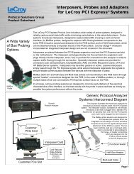
Oscilloscope <strong>Probes</strong> and<br />
PMS 300<br />
Probe Accessories
Probe selection guide<br />
LeCroy has a wide variety of world class probes and amplifiers to<br />
compliment its product line. From the ZS high impedance active<br />
probes to the WaveLink differential probing system which offers<br />
bandwidths up to 25 GHz, LeCroy probes and probe accessories<br />
provide optimum mechanical connections for signal measurement.<br />
2<br />
Front Cover:<br />
Dxx10-PT Differential Positioner Tip for the WaveLink 4-6 GHz <strong>Probes</strong>.<br />
WaveAce Oscilloscopes<br />
WaveJet 300A Oscilloscopes<br />
WaveSurfer MXs-B / MSO<br />
MXs-B Oscilloscopes<br />
HRO 12-bit Oscilloscopes<br />
WaveRunner 6 Zi<br />
Oscilloscopes<br />
WaveRunner Xi-A / MXi-A<br />
Oscilloscopes<br />
Vehicle Bus Analyzers<br />
WavePro/SDA/DDA/7 Zi/7 Zi-A<br />
Oscilloscopes<br />
WaveMaster/SDA/DDA/8 Zi/Zi-A<br />
Oscilloscopes<br />
LabMaster 9 Zi-A Oscilloscopes<br />
Active Voltage <strong>Probes</strong> - p. 4 - 7<br />
ZS1000 ✓ ✓ ✓ ✓ ✓ ✓ ✓ ✓<br />
ZS1500 ✓ ✓ ✓ ✓ ✓ ✓ ✓ ✓<br />
ZS2500 ✓ ✓ ✓ ✓ ✓ ✓<br />
Current <strong>Probes</strong> - p. 8 -11<br />
AP015 ✓ ✓ ✓ ✓ ✓ ✓ ✓ ✓<br />
CP030 ✓ ✓ ✓ ✓ ✓ ✓ ✓ ✓<br />
CP031 ✓ ✓ ✓ ✓ ✓ ✓ ✓ ✓<br />
CP150 ✓ ✓ ✓ ✓ ✓ ✓ ✓ ✓<br />
CP500 ✓ ✓ ✓ ✓ ✓ ✓ ✓ ✓<br />
Differential <strong>Probes</strong> - p. 12 - 23<br />
ZD200 ✓ ✓ ✓ ✓ ✓ ✓ ✓<br />
ZD500 ✓ ✓ ✓ ✓ ✓ ✓ ✓ ✓<br />
ZD1000 ✓ ✓ ✓ ✓ ✓ ✓ ✓ ✓<br />
ZD1500 ✓ ✓ ✓ ✓ ✓ ✓ ✓ ✓<br />
AP033 ✓ ✓ ✓ ✓ ✓ ✓ ✓ ✓<br />
AP034 ✓ ✓ ✓ ✓ ✓ ✓ ✓ ✓<br />
D410 ✓ ✓ ✓ ✓ ✓ ✓<br />
D410-PT ✓ ✓ ✓ ✓ ✓ ✓<br />
D420 ✓ ✓ ✓ ✓ ✓ ✓<br />
D420-PT ✓ ✓ ✓ ✓ ✓ ✓<br />
D500PT ✓ ✓ ✓ ✓<br />
D300A-AT ✓ ✓ ✓ ✓ ✓ ✓<br />
D600A-AT ✓ ✓ ✓ ✓<br />
D610 ✓ ✓ ✓ ✓<br />
D610-PT ✓ ✓ ✓ ✓<br />
D620 ✓ ✓ ✓ ✓<br />
D620-PT ✓ ✓ ✓ ✓<br />
Dxx05-PT-KIT ✓ ✓<br />
D830 ✓ ✓<br />
D830-PS ✓ ✓<br />
D1030 ✓ ✓<br />
D1030-PS ✓ ✓<br />
D1330 ✓ ✓<br />
D1330-PS ✓ ✓<br />
WL-PLink-A ✓ ✓ ✓<br />
LPA-2.92 ✓ ✓ ✓<br />
WL-2.92MM ✓ ✓ ✓<br />
D1305-A ✓ ✓ ✓<br />
D1305-A-PS ✓ ✓ ✓<br />
D1605-A ✓ ✓ ✓<br />
D1605-A-PS ✓ ✓ ✓<br />
D2005-A ✓ ✓ ✓<br />
LabMaster 10 Zi Oscilloscopes
Differential <strong>Probes</strong> - p. 12 - 23 (cont’d)<br />
D2005-A-PS ✓ ✓ ✓<br />
D2505-A ✓ ✓ ✓<br />
D2505-A-PS ✓ ✓ ✓<br />
High Voltage Differential <strong>Probes</strong> - p. 24 - 27<br />
ADP300 ✓ ✓ ✓ ✓ ✓ ✓ ✓ ✓<br />
ADP305 ✓ ✓ ✓ ✓ ✓ ✓ ✓ ✓<br />
AP031 ✓ ✓ ✓ ✓ ✓ ✓ ✓ ✓ ✓ ✓<br />
Differential Amplifiers - p. 28 - 31<br />
WaveAce Oscilloscopes<br />
WaveJet 300A Oscilloscopes<br />
WaveSurfer MXs-B / MSO<br />
MXs-B Oscilloscopes<br />
HRO 12-bit Oscilloscopes<br />
WaveRunner 6 Zi<br />
Oscilloscopes<br />
WaveRunner Xi-A / MXi-A<br />
Oscilloscopes<br />
Vehicle Bus Analyzers<br />
WavePro/SDA/DDA/7 Zi/7 Zi-A<br />
Oscilloscopes<br />
WaveMaster/SDA/DDA/8 Zi/Zi-A<br />
Oscilloscopes<br />
DXC200 ✓ ✓ ✓ ✓ ✓ ✓ ✓ ✓<br />
DA101 ✓ ✓ ✓ ✓ ✓ ✓ ✓ ✓<br />
DA1855A ✓ ✓ ✓ ✓ ✓ ✓ ✓ ✓<br />
DA1855A-PR2 ✓ ✓ ✓ ✓ ✓ ✓ ✓ ✓<br />
DA1855A-PR2-RM ✓ ✓ ✓ ✓ ✓ ✓ ✓ ✓<br />
DA1855A-RM ✓ ✓ ✓ ✓ ✓ ✓ ✓ ✓<br />
DXC-5100 ✓ ✓ ✓ ✓ ✓ ✓ ✓ ✓<br />
DXC100A ✓ ✓ ✓ ✓ ✓ ✓ ✓ ✓<br />
High Voltage <strong>Probes</strong> - p. 32 - 35<br />
PPE1.2KV ✓ ✓ ✓ ✓ ✓ ✓ ✓ ✓ ✓ ✓<br />
PPE20KV ✓ ✓ ✓ ✓ ✓ ✓ ✓ ✓ ✓ ✓<br />
PPE2KV ✓ ✓ ✓ ✓ ✓ ✓ ✓ ✓ ✓ ✓<br />
PPE4KV ✓ ✓ ✓ ✓ ✓ ✓ ✓ ✓ ✓ ✓<br />
PPE5KV ✓ ✓ ✓ ✓ ✓ ✓ ✓ ✓ ✓ ✓<br />
PPE6KV ✓ ✓ ✓ ✓ ✓ ✓ ✓ ✓ ✓ ✓<br />
Optical <strong>Probes</strong> - p. 36 - 39<br />
OE425 ✓ ✓ ✓ ✓ ✓ ✓ ✓<br />
OE455 ✓ ✓ ✓ ✓ ✓ ✓ ✓<br />
OE525 ✓ ✓ ✓<br />
OE555 ✓ ✓ ✓<br />
OE695G ✓ ✓ ✓<br />
Passive <strong>Probes</strong> - p. 40 - 43<br />
PP005A<br />
✓<br />
PP006A<br />
✓<br />
PP-007-WR-1<br />
✓<br />
PP008-1 ✓ ✓<br />
PP009-1 ✓ ✓ ✓<br />
PP010-1<br />
✓<br />
PP011-1<br />
✓<br />
PP016<br />
✓<br />
Transmission Line <strong>Probes</strong> - p. 44 - 47<br />
PP065 ✓ ✓ ✓ ✓ ✓ ✓ ✓<br />
PP066 ✓ ✓ ✓<br />
Note: Some probes require purchase of the amplifier and platform/cable assembly separately – Reference detailed literature for more infomation.<br />
LabMaster 9 Zi-A Oscilloscopes<br />
LabMaster 10 Zi Oscilloscopes<br />
3
Active voltage <strong>Probes</strong><br />
4
Active voltage <strong>Probes</strong><br />
Engineers must commonly probe high-frequency signals with<br />
high signal fidelity. Typical passive probes with high input R and C<br />
provide good response at lower frequencies, but inappropriately<br />
load the circuit, and distort signals, at higher frequencies. Active<br />
voltage probes feature both high input R and low input C to reduce<br />
circuit loading across the entire probe/oscilloscope bandwidth.<br />
With low circuit loading, and a form factor that allows probing in<br />
confined areas, the active voltage probe becomes the everyday<br />
probe for all different types of signals and connection points.<br />
LeCroy Active<br />
Voltage <strong>Probes</strong><br />
Model Numbers:<br />
ZS1000<br />
ZS1500<br />
ZS2500<br />
Opposite page:<br />
ZS Series High Impedance Active Probe<br />
5
ZS sERIES ACTIVE PROBES<br />
The ZS Series probes provide high impedance and an extensive set of<br />
probe tips and ground accessories to handle a wide range of probing<br />
scenarios. The high 1 MΩ input resistance and low 0.9 pF input<br />
capacitance mean this probe is ideal for all frequencies. The ZS Series<br />
probes provide full system bandwidth for all LeCroy oscilloscopes having<br />
bandwidths of 2 GHz and lower.<br />
LeCroy<br />
Active Voltage Probe<br />
Model Numbers:<br />
ZS1000<br />
ZS1500<br />
ZS2500<br />
High Impedance Reduces Circuit Loading Across<br />
Full Oscilloscope Bandwidth<br />
Engineers must commonly probe high frequency signals with high signal<br />
fidelity. Typical passive probes with high input R and C provide good<br />
response at lower frequencies, but inappropriately load the circuit, and<br />
distort signals, at higher fre quencies. The ZS Series features both high<br />
input R (1 MΩ and low input C (0.9 pF) to reduce circuit loading across the<br />
entire probe/oscilloscope bandwidth. With low circuit loading, and a form<br />
factor that allows probing in confined areas, the ZS Series becomes the<br />
everyday probe for all different types of signals and connection points. The<br />
ZS1000 is ideal for 200–600 MHz oscilloscopes. The ZS1500 is ideal for<br />
1 GHz oscilloscopes and the ZS2500 is ideal for 2 GHz oscilloscopes.<br />
PK-ZS-010<br />
Marker Bands<br />
4 colors<br />
PACC-MS005<br />
2 Footer black<br />
PK-ZS-012<br />
2.54 mm Square Pin<br />
Adapter<br />
PK-ZS-005<br />
Y-Lead<br />
Adapter<br />
PK-ZS-004<br />
Single Lead -<br />
Long<br />
PK-ZS-003<br />
Single Lead -<br />
Short<br />
PAAC-LD003<br />
Right Angle<br />
Lead - Short<br />
PAAC-LD004<br />
Right Angle<br />
Lead - Long<br />
PK-ZS-011<br />
Ground Blade - Wide<br />
PK-ZS-002<br />
Offset Ground<br />
PK-ZS-008<br />
Ground Blade - Narrow<br />
PAAC-CD008<br />
Pogo Ground Lead<br />
PAAC-CD009<br />
Pogo Ground<br />
Leaf Assembly<br />
Qty: 2<br />
PK-ZS-006<br />
Right Angle Adapter<br />
PAAC-PT005<br />
Probe Bent Tip<br />
PAAC-PT003<br />
Probe Tip IC Lead<br />
PK-ZS-013<br />
Pogo Tip<br />
PK-ZS-001<br />
Probe Tip - Standard<br />
Qty: 3<br />
PK-ZS-009<br />
Copper Pad<br />
Qty: 2<br />
PK-ZS-007R<br />
Microclip Sprung<br />
Hook, Red<br />
PK-ZS-007B<br />
Microclip Sprung<br />
Hook, Black<br />
6
ZS sERIES ACTIVE PROBES<br />
Specifications ZS1000 ZS1500 ZS2500<br />
Electrical Characteristics<br />
Bandwidth (Probe Only) 1 GHz 1.5 GHz 2.5 GHz<br />
Bandwidth (System)<br />
600 MHz at probe tip with<br />
600 MHz oscilloscope<br />
1 GHz at probe tip with<br />
1 GHz oscilloscope<br />
2 GHz at probe tip with<br />
2 GHz oscilloscope<br />
Input Capacitance<br />
0.9 pF<br />
DC Input Resistance<br />
1 MΩ<br />
Probe Offset Range N/A ±12 V<br />
Attenuation ÷10<br />
Input Dynamic Range<br />
±8 V<br />
Non-destruct Voltage<br />
20 V<br />
General Characteristics<br />
Cable Length<br />
1.3 m<br />
Ordering Information<br />
Product Description<br />
Set of 4 ZS2500, 2.5 GHz, 0.9 pF, 1 MΩ<br />
High Impedance Active <strong>Probes</strong><br />
Set of 4 ZS1500, 1.5 GHz, 0.9 pF, 1 MΩ<br />
High Impedance Active <strong>Probes</strong><br />
Set of 4 ZS1000, 1 GHz, 0.9 pF, 1 MΩ<br />
High Impedance Active <strong>Probes</strong><br />
2.5 GHz, 0.9 pF, 1 MΩ<br />
High Impedance Active Probe<br />
1.5 GHz, 0.9 pF, 1 MΩ<br />
High Impedance Active Probe<br />
1 GHz, 0.9 pF, 1 MΩ<br />
High Impedance Active Probe<br />
Product Code<br />
ZS2500-QUADPAK<br />
ZS1500-QUADPAK<br />
ZS1000-QUADPAK<br />
ZS2500<br />
ZS1500<br />
ZS1000<br />
Product Description<br />
Product Code<br />
Included with Standard Configuration (cont’d)<br />
Copper Tape (Qty 2)<br />
PK-ZS-009<br />
Pogo Tip (Qty 1)<br />
PK-ZS-013<br />
2.54mm Square Pin Adapter<br />
PK-ZS-012<br />
Channel ID Clips (Set of 4 Colors)<br />
PK-ZS-010<br />
Freehand Probe Holder<br />
PACC-MS005<br />
Bent Tip (Qty 1)<br />
PACC-PT005<br />
IC Tip (Qty 1)<br />
PACC-PT003<br />
Pogo Ground Lead (Qty 1)<br />
PACC-CD008<br />
Pogo Leaf Ground Assembly (Qty 2)<br />
PACC-CD009<br />
Included with Standard Configuration<br />
Instruction Manual, English<br />
Certificate of Calibration<br />
1-Year Warranty<br />
Straight Pin Lead – Short (Qty 1)<br />
Straight Pin Lead – Long (Qty 1)<br />
Right Angle Pin Lead – Short (Qty 1)<br />
Right Angle Pin Lead – Long (Qty 1)<br />
Y Lead Adapter (Qty 1)<br />
Micro-Grabber Pair<br />
Ground Blade – Wide<br />
Probe Tip – Standard (Qty 3)<br />
Right Angle Socket (Qty 1)<br />
Offset Ground – Z lead (Qty 1)<br />
Ground Blade – Narrow (Qty 1)<br />
PK-ZS-003<br />
PACC-LD004<br />
PACC-LD003<br />
PACC-LD004<br />
PK-ZS-005<br />
PK-ZS-007R<br />
and PK-ZS-007B<br />
PK-ZS-011<br />
PK-ZS-001<br />
PK-ZS-006<br />
PK-ZS-002<br />
PK-ZS-008<br />
Available Accessories<br />
Discrete SMD Tip<br />
Solder-In Ground<br />
Ground Spring Hook<br />
Square Pin Ground Spring<br />
PACC-PT004<br />
PACC-CD007<br />
PACC-LD001<br />
PACC-LD002<br />
7
CURRENT <strong>Probes</strong><br />
8
CURRENT <strong>Probes</strong><br />
Measuring AC and DC Currents<br />
LeCroy current probes do not require the breaking of a circuit or the<br />
insertion of a shunt to make accurate and reliable current measurements.<br />
Based on a combination of Hall effect and transformer technology, LeCroy<br />
current probes are ideal for making accurate AC, DC, and impulse current<br />
measurements.<br />
Fully Integrated with Oscilloscope<br />
Many current probes require external power supplies or amplifiers to<br />
display a waveform on the oscilloscope screen. All LeCroy current probes<br />
are powered through the LeCroy ProBus connection and require no<br />
additional hardware. Along with providing power, the ProBus connection<br />
allows the current probe and oscilloscope to communicate, resulting in<br />
current waveforms automatically displayed on screen in Amps, and<br />
calculated power traces scaled correctly in Watts. This full integration also<br />
allows for Degauss and Autozero functions to be done directly from the<br />
oscilloscope with a single button press.<br />
LeCroy<br />
Current <strong>Probes</strong><br />
Model Numbers:<br />
AP015<br />
CP030<br />
CP031<br />
CP150<br />
CP500<br />
Applications<br />
LeCroy current probes are available in a wide range of models for a wide<br />
range of applications. The full range of LeCroy current probes includes<br />
models with bandwidths up to 100 MHz, peak currents up to 700 A and<br />
sensitivities to 10 mA/div. Multiple current probes can be used together to<br />
make measurements on three-phase systems, or a single current probe<br />
can be used with a voltage probe to make accurate instantaneous power<br />
measurements. LeCroy current probes are often used in applications such<br />
as the design and test of switching power supplies, motor drives, electric<br />
vehicles, and uninterruptible power supplies.<br />
Opposite page:<br />
CP031, 30A, 100 MHz Current Probe.<br />
9
CURRENT PROBES<br />
LeCroy Current <strong>Probes</strong><br />
Model Numbers:<br />
CP031<br />
CP030<br />
AP015 / DCS015<br />
CP150<br />
CP500<br />
CP031 – 30A, 100 MHz<br />
The CP031 is LeCroy’s highest<br />
bandwidth current probe. Along<br />
with the high 100 MHz bandwidth<br />
the CP031can probe continuous<br />
currents of 30 A rms and peak<br />
currents up to 50 A. The CP031<br />
features a small form factor<br />
making it easier to probe on a<br />
crowded, compact board.<br />
CP030 – 30 A, 50 MHz<br />
The CP030 was designed with<br />
a small form factor for today’s<br />
crowded boards. The small jaw<br />
can probe currents in tight spaces<br />
and still clamp onto conductors up<br />
to 5 mm in diameter. Continuous<br />
currents of 30 A rms and peak<br />
currents of 50 A can be measured<br />
by the CP030, which also features<br />
a 50 MHz bandwidth.<br />
AP015 – 30 A, 50 MHz<br />
The AP015 current probe can<br />
measure continuous current of 30<br />
A rms and peak pulses of up to 50<br />
A for durations up to 10 seconds.<br />
This probe also features an overheating<br />
protection circuit, which<br />
will display an on-screen warning<br />
to the user to prevent damage. A<br />
probe unlock detection feature is<br />
also built in to the AP015 to<br />
ensure accurate measurements.<br />
DCS015 – Deskew<br />
Calibration Source for<br />
AP015<br />
The DCS015 calibration source has<br />
both voltage and current timealigned<br />
signals, which enables the<br />
precise deskew of voltage and current<br />
probes. Most voltage probes<br />
along with the CP031, CP030 and<br />
AP015 are compatible with the<br />
DCS015.<br />
10
CURRENT PROBES<br />
CP150 – 150 A, 10 MHz<br />
Features:<br />
• 150 Arms continuous current<br />
• 500 Apeak<br />
• 10 MHz bandwidth<br />
CP500 – 500 A, 2 MHz<br />
Features:<br />
• 500 Arms continuous current<br />
• 700 Apeak<br />
• 2 MHz bandwidth<br />
Specifications CP031 *† CP030 *† AP015 CP150 CP500<br />
Electrical Characteristics<br />
Max. Continuous Input Current 30 A 150A 500 A<br />
Bandwidth 100 MHz 50 MHz 50 MHz 10 MHz 2 MHz<br />
Max. Peak Current at Pulse Width 50 A ≤ 10 µs 50 A ≤ 10 s 500 A ≤ 30 µs 700 A<br />
Rise Time (typical) ≤ 3.5 ns ≤ 7 ns < 35 ns < 175 ns<br />
Minimum Sensitivity 20 mA/div 10 mA/div 20 0mA/div<br />
Max. In-Phase Current - 500 A 1150 A<br />
Low-Frequency Accuracy 1%<br />
AC Noise ≤ 2.5 mA - ≤ 25 mA 25 mA<br />
Coupling<br />
AC, DC, GND<br />
General Characteristics<br />
Cable Length 1.5 m 2 m 6 m<br />
Weight 240 g 300 g 500 g 630 g<br />
Max. Conductor Size (diameter) 5 mm 20 mm<br />
Interface ProBus, 1 MΩ only ‡<br />
Usage Environment<br />
Indoor<br />
Operating Temperature<br />
0˚ C to 40˚ C<br />
Max. Relative Humidity 80%<br />
Max. Altitude<br />
2000 m<br />
Maximum Insulated Wire Voltage 300 VCAT I,<br />
150 V CAT II<br />
300 VCAT I 600 VCAT I, 300 V CAT II<br />
* Guaranteed at 23 °C ±3 °C<br />
† The CP031 and CP030 are compatible with LeCroy X-Stream oscilloscopes running firmware version 4.3.1.1 or greater.<br />
‡ Requires AP-1M for use with 50 Ω input only oscilloscopes<br />
Ordering Information<br />
Product Description<br />
Product Code<br />
Product Description<br />
Product Code<br />
30 A; 100 MHz Current Probe - AC/DC; 30 A rms;<br />
50 A peak Pulse<br />
30 A; 50 MHz Current Probe - AC/DC; 30 A rms;<br />
50 A peak Pulse<br />
30 A; 50 MHz Current Probe - AC/DC; 30 A rms;<br />
50 A peak Pulse<br />
CP031<br />
CP030<br />
AP015<br />
150 A; 10 MHz Current Probe - AC/DC; 150 A rms;<br />
500 A peak Pulse<br />
500 A; 2 MHz Current Probe - AC/DC; 500 A rms;<br />
700 A peak Pulse<br />
Deskew Calibration Source for AP015<br />
CP150<br />
CP500<br />
DCS015<br />
11
12<br />
Differential <strong>Probes</strong>
Differential <strong>Probes</strong><br />
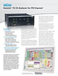
Differential active probes are like two probes in one.<br />
Instead of measuring a test point in relation to a ground<br />
point (like single-ended active probes), differential probes<br />
measure the difference in voltage of a test point in relation<br />
to another test point.<br />
LeCroy<br />
Differential <strong>Probes</strong><br />
Model Numbers:<br />
200 MHz - 1.5 GHz<br />
ZD200<br />
ZD500<br />
ZD1000<br />
ZD1500<br />
AP033<br />
AP034<br />
3 GHz - 6 GHz<br />
D300A-AT<br />
D410<br />
D420<br />
D500PT<br />
D600A-AT<br />
D610<br />
D620<br />
8 GHz - 13 GHz<br />
D830<br />
D1030<br />
D1330<br />
11 GHz - 25 GHz<br />
D1305-A<br />
D1605-A<br />
D2005-A<br />
D2505-A<br />
Opposite page:<br />
WaveLink ® High Bandwidth Differential Probing System<br />
(13 GHz – 25 GHz)<br />
13
ZD Series differential PROBES<br />
The ZD Series probes provide wide dynamic range, excellent noise and<br />
loading performance and an extensive set of probe tips, leads, and ground<br />
accessories to handle a wide range of probing scenarios. The low 1 pF<br />
capacitance means this probe is ideal for all frequencies. The ZD Series<br />
differential probes provide full system bandwidth for all LeCroy Oscilloscopes<br />
1.5 GHz and lower.<br />
LeCroy<br />
Differential Probe<br />
Model Numbers:<br />
ZD200<br />
ZD500<br />
ZD1000<br />
ZD1500<br />
Fully Integrated<br />
With the ProBus interface, the ZD500, 1000, and 1500 becomes an integral<br />
part of the oscilloscope. All probe gain and offset controls are transparent to<br />
the user, making it easier to probe the circuit without concern for which gain<br />
setting to choose. When used with a LeCroy digital oscilloscope, no external<br />
power supply is required.<br />
Wide Dynamic Range<br />
The ZD500, 1000, 1500 probes provides transparent probe attenuation so<br />
signals are always optimized for the display. The differential range is 18 Vp-p<br />
with a differential offset of ±8 and common mode range of ±10 V, making<br />
this versatile for every probing application.<br />
Wide Applications<br />
The wide dynamic range of 16 Vp-p and offset range of ±8 suit this probe to<br />
a wide range of applications and signal types. The ZD differential probes are<br />
ideally suited for Automotive, Serial Data, power, and general purpose use.<br />
PACC-MS001<br />
Hands Free Probe Holder<br />
ZD1500 / ZD1000 / ZD500 Probe<br />
PCF200<br />
Probe Calibration Fixture<br />
PACC-ZD001<br />
Y Lead<br />
Adapter<br />
PACC-ZD002<br />
Solder-In-Lead<br />
Qty: 2<br />
PACC-ZD003<br />
Spring-loaded<br />
Ground (Long)<br />
Qty: 2<br />
PACC-ZD004<br />
Tip Saver<br />
Qty: 2<br />
PACC-ZD005<br />
Swivel Tip Adapter<br />
PACC-ZD006<br />
Small IC Adapter<br />
Qty: 2<br />
PACC-PT001<br />
Straight Tip<br />
Qty: 4<br />
PACC-CD008<br />
Spring-loaded<br />
Ground (Short)<br />
Qty: 2<br />
PACC-LD003<br />
Right Angle<br />
Connector (Short)<br />
Qty: 2<br />
PK006-4<br />
Micro-Grabber<br />
Qty: 2<br />
PACC-CL001<br />
Mini-Grabber<br />
Qty: 2<br />
14<br />
PACC-LD004<br />
Right Angle<br />
Connector (long)<br />
Qty: 2
Zd series differential PROBES<br />
Specifications ZD1500 ZD1000 ZD500 ZD200<br />
Electrical Characteristics<br />
Bandwidth (Warranted) 1500 MHz 1000 MHz 500 MHz 200 MHz<br />
Bandwidth (Typical) 1700 MHz 1200 MHz 650 MHz -<br />
Risetime 10–90% (Typical) 270 ps 375 ps 650 ps 1.75 ns<br />
Risetime 20–80% (Typical) 200 ps 280 ps 500 ps -<br />
LF Attenuation Accuracy (Warranted) 2% 1%<br />
Zero Offset (Typical)<br />
(within 15 minutes after autozero)<br />
5 mV<br />
-<br />
System Noise (Typical) 1.75 mVrms 1.75 mVrms 1.3 mVrms -<br />
Probe Noise Density (Typical) 38 nV/rt (Hz) 3 mV rms<br />
Input Differential Range (Nominal) ±8 V (16 Vp-p) ± 20 V<br />
Differential Offset Range (Nominal) ±18 V -<br />
Offset Gain Accuracy (Typical) 2% -<br />
Common Mode Range (Nominal) ±10 V ± 60 V<br />
Maximum Non-destruct Voltage<br />
30 V<br />
(Nominal)<br />
-<br />
CMRR (Typical)<br />
DC Input Resistance (Nominal)<br />
Differential Input Capacitance<br />
(Typical)<br />
60 dB 50/60 Hz<br />
30 dB 20 MHz<br />
25 dB @ 1500 MHz<br />
60 dB 50/60 Hz<br />
30 dB 20 MHz<br />
25 dB @ 1000 MHz<br />
50 kΩ (Common Mode)<br />
120 kΩ (Differential Mode)<br />
60 dB 50/60 Hz<br />
30 dB 20 MHz<br />
25 dB 500 MHz<br />
80 dB @ 60 Hz<br />
50 dB@10 MHz<br />
250 kΩ (Common Mode)<br />
1 MΩ (Differential Mode)<br />
< 1.0 pF 3.5 pF<br />
Ordering Information<br />
Product Description<br />
Product Code<br />
Product Description<br />
Product Code<br />
200 MHz, 3.5 pF, 1 MΩ Active Differential Probe ZD200<br />
500 MHz, 1.0 pF, 1 MΩ Active Differential Probe ZD500<br />
1 GHz, 1.0 pF, 1 MΩ Active Differential Probe ZD1000<br />
1.5 GHz, 1.0 pF, 1 MΩ Active Differential Probe ZD1500<br />
Standard Accessories<br />
Y Lead Adapter, Qty 1<br />
Solder-In Lead, Qty 2<br />
Long Spring Loaded Bendable Ground, Qty 2<br />
Tip Saver, Qty 2<br />
Swivel Tip Adapter<br />
Small IC Adapter, Qty 2<br />
Replacement Accessory Kit for ZD200<br />
Replacement Leadset for ZD200<br />
Straight Tip, Qty 4<br />
Right Angle Connector Short, Qty 2<br />
PACC-ZD001<br />
PACC-ZD002<br />
PACC-ZD003<br />
PACC-ZD004<br />
PACC-ZD005<br />
PACC-ZD006<br />
PACC-ZD007<br />
PACC-ZD008<br />
PACC-PT001<br />
PACC-LD003<br />
Right Angle Connector Long, Qty 2<br />
Micrograbber, Qty 2<br />
Minigrabber, Qty 2<br />
Short Spring Loaded Bendable Ground, Qty 2<br />
Probe Calibration Fixture, Qty 1<br />
ZD Replacement Kit<br />
Hands Free Probe Holder, Qty1<br />
PACC-LD004<br />
PK006-4<br />
PACC-CL001<br />
PACC-CD008<br />
PCF200<br />
PK111<br />
PACC-MS001<br />
15
WAVelink LOw bandwidth differential PROBES<br />
-PT<br />
GHz<br />
AL<br />
0-PT-KIT<br />
LeCroy WaveLink<br />
Low Bandwidth Differential<br />
Probe and Accessory<br />
Model Numbers:<br />
D410<br />
D410-PT<br />
D420<br />
D420-PT<br />
D500PT<br />
D300A-AT<br />
D600A-AT<br />
D610<br />
D620-PT<br />
6 GHz<br />
D610-PT<br />
6 GHz<br />
D620-PT<br />
6 GHz<br />
D610-PT<br />
D620<br />
D620-PT<br />
WL-PBus<br />
WL-PLink<br />
Dx20-PT-KIT<br />
Dx20-SP<br />
Dx20-QC<br />
Dx20-PT-KIT<br />
Dx20-SI<br />
Dx10-PT-KIT<br />
IT<br />
)<br />
WaveLink ® probes provide industry leading technology for wideband signal<br />
connection to test instruments. The first differential probes to employ SiGe<br />
technology, they deliver full system bandwidth when used with WaveRunner, ®<br />
WavePro, ® WaveMaster, ® DDA and SDA oscilloscopes up to 6 GHz.<br />
WaveLink probes:<br />
• Maintain good loading characteristics across the frequency span<br />
• Optimized for gain, noise and bandwidth for optimal performance<br />
• Offer broad range of dynamic range and noise over gain settings by<br />
incorporating automatic probe attenuation changes<br />
DDA ≥ 4 GHz<br />
WaveLink is the first differential probe to use a unique calibration process<br />
WavePro ≥ 4 GHz<br />
to achieve superb waveform fidelity for routine voltage measurements.<br />
Calibration coefficients “fine tune” COLORED the frequency DWGS FOR response DATASHEET of each WaveLink<br />
probe and are individually determined ProLinkduring factory calibration and programmed<br />
into the probe. The SDA, WaveLink DDA, WaveMaster, WaveRunner, or<br />
WL-PLink<br />
SDA ≥ 4 GHz<br />
WavePro Series oscilloscopes read this data and use it to digitally compensate<br />
WaveMaster<br />
DDA ≥ 4 GHz<br />
the entire system response WavePro for ≥ superior 4 GHz fidelity.<br />
D500PT<br />
(compatible D600A-AT with oscilloscopes<br />
D500PT-Tip D500PT<br />
D600A-AT<br />
Dx10-HITEMP<br />
(Optional)<br />
SDA ≥ 4 GHz<br />
WaveMaster<br />
D610<br />
6 GHz<br />
4 GHz–6 GHz WaveLink configurations<br />
from 4 GHz to 6 GHz)<br />
COLORED DWGS FOR DATASHEET<br />
Dx10-SI<br />
Dx10-PT-KIT<br />
(Optional)<br />
ProLink<br />
WL-PLink<br />
WaveLink<br />
D610<br />
6 GHz Dx10-SP<br />
Dx10-QC<br />
Dx20-HiTemp<br />
(Optional)<br />
D500PT-Tip<br />
Dx10-SP<br />
SDA ≤ 4 GHz Dx10-QC<br />
DDA ≤ 4 GHz<br />
Dx10-HITEMP WavePro ≤ 4 GHz<br />
Dx10-SI Dx20-HiTemp<br />
(Optional) Dx10-PT-KIT<br />
(Optional)<br />
WaveRunner (Optional)<br />
WaveSurfer<br />
D620<br />
6 GHz<br />
D610-PT<br />
6 GHz<br />
D620<br />
D610-PT<br />
6 GHz Dx20-SP 6 GHz<br />
Dx20-QC<br />
Dx20-SI<br />
Dx20-PT-Kit<br />
(Optional)<br />
Dx10-PT-Kit<br />
D620-PT<br />
6 GHz<br />
D620-PT<br />
6 GHz<br />
Dx20-PT-Kit<br />
Dx20-SP<br />
Dx20-QC<br />
Dx20-SI<br />
Dx20-PT-Kit<br />
Dx20-PT-Kit<br />
Dx10-PT-Kit<br />
(Optional)<br />
≤ 4 GHz WaveLink configurations<br />
(compatible with oscilloscopes<br />
up to and including 4 GHz)<br />
SDA ≤ 4 GHz<br />
DDA ≤ 4 WavePro ≤ 4 GHzProBus<br />
WaveRunner WL-PBus<br />
WaveSurfer WaveLink<br />
-PT<br />
GHz<br />
D420-PT<br />
4 GHz<br />
D500PT<br />
D410<br />
4 GHz<br />
ProBus<br />
WL-PBus<br />
WaveLink<br />
D420<br />
4 GHz<br />
D410-PT<br />
4 GHz<br />
D420-PT<br />
4 GHz<br />
D300A-AT<br />
D410-PT<br />
4 GHz<br />
D420-PT<br />
4 GHz<br />
D500PT<br />
D410<br />
4 GHz<br />
D420<br />
4 GHz<br />
D410-PT<br />
4 GHz<br />
D420-PT<br />
4 GHz<br />
D300A-AT<br />
Dx20-PT-KIT<br />
D500PT-Tip<br />
Dx10-SP<br />
Dx10-SI<br />
Dx20-SP<br />
Dx20-SI<br />
Dx20-PT-Kit<br />
0-PT-KIT<br />
16<br />
Dx20-SP<br />
Dx20-SI<br />
Dx20-PT-KIT<br />
Dx10-HiTemp<br />
(Optional)<br />
D500PT-Tip<br />
Dx10-PT-Kit<br />
(Optional)<br />
Dx20-HiTemp<br />
(Optional)<br />
Dx10-SP<br />
Dx10-SI<br />
Dx20-PT-Kit<br />
(Optional)<br />
Dx20-SP<br />
Dx20-SI<br />
Dx10-PT-Kit<br />
Dx20-PT-Kit<br />
-KIT<br />
AL)<br />
Dx10-PT-KIT<br />
Dx10-HiTemp<br />
(Optional)<br />
Dx10-PT-Kit<br />
(Optional)<br />
Dx20-HiTemp<br />
(Optional)<br />
Dx20-PT-Kit<br />
(Optional)<br />
Dx10-PT-Kit
WAVelink Low bandwidth differential PROBES<br />
Specifications d610 d620 d410 d420 D600A-AT D300A-AT D500PT<br />
Bandwidth, System DC to -3 dB<br />
PT Positioner Lead 6 GHz 1 4 GHz 1 6 GHz 3 GHz 5 GHz<br />
SI Solder-In Lead 6 GHz 1 4 GHz 1 N/A<br />
QC Interconnect Lead 4 GHz N/A<br />
SP Interconnect Lead 3 GHz N/A<br />
HiTemp Solder-In Lead 6 GHz 4 GHz N/A N/A N/A<br />
Rise Time (10–90)<br />
PT Positioner Lead < 75 ps < 112 ps < 75 ps 1 < 130 ps 1 < 90 ps 1<br />
SI Solder-In Lead < 75 ps < 112 ps N/A<br />
QC Interconnect Lead < 122.5 ps N/A<br />
SP Interconnect Lead < 150 ps N/A<br />
HiTemp Solder-In Lead < 75 ps < 112 ps N/A N/A N/A<br />
LF Attenuation Accuracy 1<br />
2% < 1.25 Vp-p<br />
5% 1.25 Vp-p<br />
to 2.5 Vp-p<br />
2% < 2.25 Vp-p<br />
5% 2.5 Vp-p<br />
to 5 Vp-p<br />
2% < 1.25 Vp-p<br />
5% 1.25 Vp-p<br />
to 2.5 Vp-p<br />
2% < 2.25 Vp-p<br />
5% 2.5 Vp-p<br />
to 5 Vp-p<br />
2% 0±1.2 V (with 0 V common mode)<br />
5% ±1.2 V ±2.4 V (with 0 V common mode)<br />
Zero Offset<br />
(within 15 minutes after autozero)<br />
< 2.5 mV 1 < 5 mV 1 < 2.5 mV 1 < 5 mV 1 < 10 mV 1<br />
Offset Gain Accuracy 1% of offset value 1 N/A<br />
Input Differential Range 2.5 Vp-p 5 Vp-p 2.5 Vp-p 5 Vp-p 4.8 Vp-p<br />
Differential Offset Range ±3 V 0 V<br />
Common Mode Range<br />
(max. peak voltage ±4 V ±2.4 V<br />
either input to ground)<br />
DC Input Resistance 100 kΩ differential 4 kΩ differential<br />
50 kΩ single-ended 2 kΩ single-ended<br />
AC Loading (differential Zmin) 200 Ω 200 Ω 200 Ω 200 Ω 120 Ω 600 Ω 200 Ω<br />
CMRR > 30 dB@10 MHz > 30 dB@10 MHz > 40 dB@1 MHz > 25 dB@ 1 GHz<br />
> 26 dB@ 6 GHz > 26 dB@ 3.5 GHz > 30 dB@3 GHz > 19 dB@ 3 GHz<br />
> 20 dB@ 6 GHz (D600A-AT only) > 16 dB@ 5 GHz<br />
Differential Input<br />
Capacitance@1 GHz<br />
SI Solder-In Lead 210 fF 120 fF 210 fF 120 fF N/A<br />
PT Positioner Lead 290 fF 290 fF 290 fF 290 fF 170 fF<br />
QC Interconnect Lead 550 fF 530 fF 550 fF 530 fF N/A<br />
SP Interconnect Lead 980 fF 980 fF 980 fF 980 fF N/A<br />
HiTemp Solder-In Lead 210 fF 120 fF 210 fF 120 fF N/A<br />
Noise<br />
(System referred to probe input)<br />
2.8 mV<br />
rms<br />
4.8 mV<br />
rms<br />
2.3 mV<br />
rms<br />
4.3 mV<br />
rms<br />
5.8 mV<br />
rms<br />
5.0 mV<br />
rms<br />
5.8 mV<br />
rms<br />
1 Warranted specification.<br />
Ordering Information<br />
Product Description<br />
Product Code<br />
Product Description<br />
Product Code<br />
Probe Tip Modules<br />
WaveLink 6 GHz 2.5 Vp-p Differential Amplifier Small Tip Module D610*<br />
WaveLink 4 GHz 2.5 Vp-p Differential Amplifier Small Tip Module D410*<br />
WaveLink 6 GHz 5 Vp-p Differential Amplifier Small Tip Module D620*<br />
WaveLink 4 GHz 5 Vp-p Differential Amplifier D420*<br />
Small Tip Module<br />
WaveLink 6 GHz Differential Amplifier Module with Adjustable Tip D600A-AT*<br />
WaveLink 3 GHz Differential Amplifier Module with Adjustable Tip D300A-AT*<br />
WaveLink 5 GHz Differential Amplifier Module with Positioner Tip D500PT*<br />
WaveLink 6 GHz, 2.5 Vp-p Differential Positioner Tip<br />
D610-PT*<br />
WaveLink 6 GHz, 5 Vp-p Differential Positioner Tip<br />
D620-PT*<br />
WaveLink 4 GHz, 2.5 Vp-p Differential Positioner Tip<br />
D410-PT*<br />
WaveLink 4 GHz, 5 Vp-p Differential Positioner Tip<br />
D420-PT*<br />
* For a complete probe, order a WL-PLink, or WL-PBus Platform/Cable Assembly<br />
with the probe tip module.<br />
Probe Bodies<br />
WaveLink ProLink Platform/Cable Assembly (4 – 6 GHz)<br />
WaveLink ProBus Platform/Cable Assembly (4 GHz)<br />
WL-PLink<br />
WL-PBus<br />
Probe Leads and Accessories<br />
Differential Positioner Tip with Accessories<br />
(for use with D610 or D410)<br />
Differential Positioner Tip with Accessories<br />
(for use with D620 or D420)<br />
WaveLink Temperature Extension Cables for Dx10.<br />
Includes (1) Set of Matched 30” High Temperature Cables,<br />
(1) Solder-In Lead Set<br />
WaveLink Temperature extension cables for Dx20.<br />
Includes (1) Set of Matched 30” High Temperature Cables,<br />
(1) Solder-In Lead Set<br />
Service Options<br />
NIST Traceable Calibration with Test Data †<br />
(one module)<br />
† CCNIST NIST traceable calibration with test data is an available option<br />
for D610, D620, D410, D420, D500PT, D600A-AT, or D300A-AT only<br />
when ordered with either a WL-PLink or WL-PBus.<br />
Dx10-PT-Kit<br />
Dx20-PT-Kit<br />
Dx10-HiTemp<br />
Dx20-HiTemp<br />
D600A-AT-CCNIST<br />
D300A-AT-CCNIST<br />
D500PT-CCNIST<br />
D610-CCNIST<br />
D620-CCNIST<br />
D410-CCNIST<br />
D420-CCNIST<br />
17
WAVelink medium bandwidth differential PROBEs<br />
General Purpose Probe with Range of Capabilities<br />
LeCroy’s WaveLink 8-13 GHz Differential <strong>Probes</strong> are a medium bandwidth,<br />
general purpose probing solution with high input dynamic range and<br />
offset range capability. These probes support solder-in, positioner<br />
(browser), square pin and SMA/SMP cabled tip/lead connections. The range<br />
of capabilities is ideal for a variety of high speed DDR signals where high<br />
dynamic range and large offset requirements are common.<br />
LeCroy WaveLink<br />
Medium Bandwidth Differential<br />
Probe and Accessory<br />
Model Numbers:<br />
D830<br />
D1030<br />
D1330<br />
Dxx30-PT-KIT<br />
Dxx30-SMA-SMP-LEADS<br />
WL-PLINK-CASE<br />
COLOR DWG FOR DATASHEET<br />
Features and Benefits<br />
• Choice of 8, 10, or 13 GHz bandwidth models<br />
• 3.5 Vpk-pk dynamic range<br />
• ±4 V offset range<br />
• Ideal for DDR3, DDR4, LPDDR3<br />
• Deluxe soft carrying case<br />
• Wide variety of tips and leads<br />
– Solder-In Lead<br />
– Positioner (Browser) Tip<br />
– SMA/SMP Lead<br />
– Square Pin Lead<br />
• SMA/SMP lead set accessory does not require purchase<br />
of a different amplifier<br />
• Deluxe Soft Carrying Case<br />
LabMaster 9 Zi-A/10 Zi<br />
WaveMaster/SDA/<br />
DDA 8 Zi/Zi-A ≥ 8 GHz<br />
WL-PLINK-CASE<br />
Platform/Cable Assembly<br />
(Included in Dxx30-PS)<br />
D830<br />
8GHz<br />
Differential<br />
Amplifier<br />
D1030<br />
10GHz<br />
Differential<br />
Amplifier<br />
D1330<br />
13GHz<br />
Differential<br />
Amplifier<br />
Dxx30-SMA-SMP<br />
SMA/SMP Lead Set<br />
(Optional)<br />
Dxx30-PT<br />
Positioner Tip Browser<br />
(Included in Dxx30-PS)<br />
Dxx30-SI<br />
Solder-In Lead (Qty. 2)<br />
Dxx30-SP<br />
Square Pin<br />
18
WAVelink medium bandwidth differential PROBEs<br />
Specifications D830, D830-PS D1030, D1030-PS D1330, D1330-PS<br />
Bandwidth<br />
Dxx30-SI, Dxx30-SMA-SMP, and Dxx30-PT Tips<br />
8 GHz (probe only, guaranteed)<br />
8 GHz (system bandwidth,<br />
when used with 808Zi/Zi-A, typical)<br />
Dxx30-SI, Dxx30-SMA-SMP, and Dxx30-PT Tips<br />
10 GHz (probe only, guaranteed)<br />
10 GHz (system bandwidth,<br />
when used with 813Zi/Zi-A, typical)<br />
Dxx30-SI and Dxx30-SMA-SMP Tips<br />
13 GHz (probe only, guaranteed)<br />
13 GHz (system bandwidth,<br />
when used with 813Zi/Zi-A, typical)<br />
Dxx30-SP Tip<br />
3 GHz (probe only, guaranteed)<br />
3 GHz (system bandwidth,<br />
when used with 808Zi/Zi-A, typical)<br />
Dxx30-SP Tip<br />
3 GHz (probe only, guaranteed)<br />
3 GHz (system bandwidth,<br />
when used with 813Zi/Zi-A, typical)<br />
Dxx30-PT Tip<br />
10 GHz (probe only, guaranteed)<br />
10 GHz (system bandwidth,<br />
when used with 813Zi/Zi-A, typical)<br />
Dxx30-SP Tip<br />
3 GHz (probe only, guaranteed)<br />
3 GHz (system bandwidth,<br />
when used with 813Zi/Zi-A, typical)<br />
Rise Time (10–90%)<br />
Dxx30-SI, Dxx30-SMA-SMP, and Dxx30-PT Tips<br />
50 ps (typical)<br />
System rise time measured<br />
with ≥8 GHz oscilloscope<br />
Dxx30-SI, Dxx30-SMA-SMP, and Dxx30-PT Tips<br />
40 ps (typical)<br />
System rise time measured<br />
with ≥13 GHz oscilloscope<br />
Dxx30-SI and Dxx30-SMA-SMP Tips<br />
35 ps (typical)<br />
System rise time measured<br />
with ≥13 GHz oscilloscope<br />
Dxx30-SP Tip<br />
132 ps (typical) System rise time measured<br />
with ≥8 GHz oscilloscope<br />
Dxx30-SP Tip<br />
132 ps (typical) System rise time measured<br />
with ≥13 GHz oscilloscope<br />
Dxx30-PT Tip<br />
40 ps (typical) System rise time measured<br />
with ≥13 GHz oscilloscope<br />
Rise Time (20–80%)<br />
Dxx30-SI, Dxx30-SMA-SMP, and Dxx30-PT Tips<br />
37.5 ps (typical)<br />
System rise time measured<br />
with ≥8 GHz oscilloscope<br />
Dxx30-SI, Dxx30-SMA-SMP, and Dxx30-PT Tips<br />
30 ps (typical)<br />
System rise time measured<br />
with ≥13 GHz oscilloscope<br />
Dxx30-SP Tip<br />
132 ps (typical) System rise time measured<br />
with ≥13 GHz oscilloscope<br />
Dxx30-SI and Dxx30-SMA-SMP Tips<br />
26 ps (typical)<br />
System rise time measured<br />
with ≥13 GHz oscilloscope<br />
Dxx30-SP Tip<br />
100 ps (typical)<br />
System rise time measured<br />
with ≥8 GHz oscilloscope<br />
Dxx30-SP Tip<br />
100 ps (typical)<br />
System rise time measured<br />
with ≥13 GHz oscilloscope<br />
Dxx30-PT Tip<br />
30 ps (typical)<br />
System rise time measured<br />
with ≥13 GHz oscilloscope<br />
Noise (Probe)<br />
WAVelink high bandwidth differential PROBES<br />
Ultra-wideband Architecture for Superior Signal Fidelity<br />
LeCroy’s WaveLink ® high bandwidth differential probes utilize advanced<br />
differential traveling wave (distributed) amplifier architecture to achieve<br />
superior high frequency true analog broadband performance. Traveling<br />
wave (distributed) amplifiers are commonly used in ultra high frequency<br />
broadband amplifiers. This multi-stage amplifier architecture maximizes<br />
gain per stage and minimizes probe attenuation, which provides very low<br />
probe noise and fast rise times.<br />
LeCroy WaveLink<br />
High Bandwidth Differential<br />
Probe and Accessory<br />
Model Numbers:<br />
D1305-A<br />
D1605-A<br />
D2005-A<br />
D2505-A<br />
LPA-2.92<br />
WL-2.92MM<br />
WL-PLINK-A<br />
Features & Benefits<br />
• Up to 25 GHz bandwidth (probe + oscilloscope)<br />
• System rise time as fast as 13 ps (20–80%)<br />
• Highest bandwidth Solder-In solution (25 GHz)<br />
• Ultra-compact browsertip (22 GHz)<br />
• Superior probe impedance minimizes AC loading on device under<br />
test (DUT)<br />
• Carbon-composite browser tips optimize signal fidelity and loading<br />
• Probe noise as low as 14 nV/√Hz (1.6 Vrms)<br />
• Low probe attenuation<br />
• Large operating voltage range<br />
±4 V common mode range<br />
±2.5 V offset range<br />
2.0 V pk-pk dynamic range<br />
• Long length Solder-In tip with field replaceable resistors<br />
LabMaster 10 Zi<br />
LabMaster 9 Zi-A<br />
WaveMaster 8 Zi/Zi-A<br />
SDA11000<br />
SDA13000<br />
SDA18000<br />
WL-PLINK-A<br />
Platform/Cable<br />
Assembly:<br />
(included in<br />
D1x05-A-PS)<br />
WL-2.92MM<br />
Platform/Cable<br />
Assembly<br />
(included in<br />
D2x05-A-PS)<br />
LPA-2.92<br />
LPA 2.92 to ProLink Adapter:<br />
D1305-A<br />
13 GHz<br />
D1605-A<br />
16 GHz<br />
D2005-A<br />
20 GHz<br />
D2505-A<br />
25 GHz<br />
Differential Amplifier<br />
Dxx05-SI<br />
Solder-In Lead<br />
Dxx05-PT<br />
Positioner Tip<br />
Browser<br />
20
WAVelink high bandwidth differential PROBES<br />
Specifications D1305-A, D1305-A-PS D1605-A, D1605-A-PS D2005-A, D2005-A-PS D2505-A, D2505-A-PS<br />
Bandwidth<br />
Dxx05-SI and Dxx05-PT Tips<br />
13 GHz (probe only, guaranteed)<br />
13 GHz (system bandwidth,<br />
when used with 813Zi, typical)<br />
Dxx05-SI and Dxx05-PT Tips<br />
16 GHz (probe only, guaranteed)<br />
16 GHz (system bandwidth,<br />
when used with 816Zi, typical)<br />
Dxx05-SI and Dxx05-PT Tips<br />
20 GHz (probe only, guaranteed)<br />
20 GHz (system bandwidth,<br />
when used with 820Zi, typical)<br />
Dxx05-SI Lead<br />
25 GHz (probe only, guaranteed)<br />
25 GHz (system bandwidth,<br />
when used with 825Zi, typical)<br />
Rise Time (10–90%)<br />
Rise Time (20–80%)<br />
Dxx05-SI and Dxx05-PT Tips<br />
32.5 ps (typical)<br />
System rise time measured<br />
with ≥ 13 GHz oscilloscope)<br />
Dxx05-SI and Dxx05-PT Tips<br />
24.5 ps (typical)<br />
System rise time measured<br />
with ≥ 13 GHz oscilloscope<br />
Noise (Probe) < 14 nV/√Hz (1.6 mV rms )<br />
(typical)<br />
Referred to input,<br />
13 GHz bandwidth<br />
Noise (System) < 23 nV/√Hz (2.7 mV rms )<br />
(typical) Referred to input,<br />
13 GHz bandwidth<br />
Input<br />
Input Dynamic Range<br />
Input Common Mode Voltage Range<br />
Input Offset Voltage Range<br />
Non-destructive Input Range<br />
Dxx05-SI and Dxx05-PT Tips<br />
28 ps (typical)<br />
System rise time, measured<br />
with ≥ 16 GHz oscilloscope<br />
Dxx05-SI and Dxx05-PT Tips<br />
21 ps (typical)<br />
System rise time measured<br />
with ≥ 16 GHz oscilloscope<br />
< 14 nV/√Hz (1.8 mV rms )<br />
(typical)<br />
Referred to input,<br />
16 GHz bandwidth<br />
< 23 nV/√Hz (2.9 mVrms)<br />
(typical) Referred to input,<br />
16 GHz bandwidth<br />
2.0 V pk-pk , ±1 V (nominal)<br />
±4 V (nominal)<br />
±2.5 V Differential (nominal)<br />
±10 V (nominal)<br />
Dxx05-SI and Dxx05-PT Tips<br />
20 ps (typical)<br />
System rise time measured<br />
with ≥ 20 GHz oscilloscope<br />
Dxx05-SI and Dxx05-PT Tips<br />
15 ps (typical)<br />
System rise time measured<br />
with ≥ 20 GHz oscilloscope<br />
< 18 nV/√Hz (2.5 mV rms )<br />
(typical)<br />
Referred to input,<br />
20 GHz bandwidth<br />
< 28 nV/√Hz (4.0 mV rms )<br />
(typical) Referred to input,<br />
20 GHz bandwidth<br />
Attenuation 3.5x (nominal) 4.5x (nominal)<br />
DC Input Resistance (nominal)<br />
1.1 kΩ Differential<br />
100 kΩ Common mode<br />
Dxx05-PT Tip<br />
22 GHz (system bandwidth,<br />
when used with 825Zi, typical)<br />
20 GHz (probe only, guaranteed)<br />
Dxx05-SI Lead<br />
17.5 ps (typical)<br />
System rise time measured<br />
with ≥ 25 GHz oscilloscope<br />
Dxx05-PT Tip<br />
19 ps (typical)<br />
System rise time measured<br />
with ≥ 25 GHz oscilloscope<br />
Dxx05-SI Lead<br />
13 ps (typical)<br />
System rise time measured<br />
with ≥ 25 GHz oscilloscope<br />
Dxx05-PT Tip<br />
14 ps (typical)<br />
System rise time measured<br />
with ≥ 25 GHz oscilloscope<br />
< 18 nV/√Hz (2.8 mV rms )<br />
(typical)<br />
Referred to input,<br />
25 GHz bandwidth<br />
< 28 nV/√Hz (4.5 mV rms )<br />
(typical) Referred to input,<br />
25 GHz bandwidth<br />
Product Description<br />
Product Code<br />
Product Description<br />
Product Code<br />
Complete Probe Systems<br />
13 GHz Complete Probe System with Solder-In Tip<br />
(13 GHz) and Positioner Tip Browser (13 GHz)<br />
16 GHz Complete Probe System with Solder-In Tip<br />
(16 GHz) and Positioner Tip Browser (16 GHz)<br />
20 GHz Complete Probe System with Solder-In Tip<br />
(20 GHz) and Positioner Tip Browser (20 GHz)<br />
25 GHz Complete Probe System with Solder-In Tip<br />
(25 GHz) and Positioner Tip Browser (22 GHz)<br />
Amplifier and Probe Tip Modules<br />
WaveLink D1305 13 GHz/1.6 V pk-pk Differential Probe<br />
Amplifier with Dxx05-SI Solder-In Tip (Qty. 2)<br />
WaveLink D1605 16 GHz/1.6 V pk-pk Differential Probe<br />
Amplifier with Dxx05-SI Solder-In Tip (Qty. 2)<br />
WaveLink D2005 20 GHz/1.6 V pk-pk Differential Probe<br />
Amplifier with Dxx05-SI Solder-In Tip (Qty. 2)<br />
WaveLink D2505 25 GHz/1.6 V pk-p Differential Probe<br />
Amplifier with Dxx05-SI Solder-In Tip (Qty. 2)<br />
Probe Platform/Cable Assemblies and Adapters<br />
WaveLink ProLink Platform/Cable Assembly Kit<br />
for ≥ 13 GHz WaveLink <strong>Probes</strong><br />
WaveLink 2.92 mm Platform/Cable Assembly Kit<br />
for ≥ 20 GHz WaveLink <strong>Probes</strong><br />
ProLink to 2.92 mm Adapter with Probe Power<br />
and Communication Pass Through<br />
D1305-A-PS<br />
D1605-A-PS<br />
D2005-A-PS<br />
D2505-A-PS<br />
D1305-A<br />
D1605-A<br />
D2005-A<br />
D2505-A<br />
WL-PLINK-A<br />
WL-2.92MM<br />
LPA-2.92<br />
Positioner Tip (Browser) Kits<br />
WaveLink Dxx05-PT (Up to 22 GHz Rating) Adjustable<br />
Positioner Tip Kit. For use with Dxx05 Amplifiers<br />
Accessories<br />
Cascade Microtech EZ-Probe Positioner<br />
Probe Deskew and Calibration Test Fixture<br />
Calibration Options<br />
NIST Calibration for D1305. Includes Test Data<br />
NIST Calibration for D1605. Includes Test Data<br />
NIST Calibration for D2005. Includes Test Data<br />
NIST Calibration for D2505. Includes Test Data<br />
Replacement Parts<br />
Replacement Dxx05-SI 13–25 GHz Solder-In Lead with<br />
Qty. 5 Spare Resistors<br />
Replacement SI Resistor Kit for Dxx05-SI Solder-In Tip<br />
Replacement Dxx05-PT Positioner Tip<br />
Qty. 4 Replacement Carbon Composite Pogo-pin Tips<br />
Replacement Probe Tip Holder Kit<br />
Replacement Platform/Cable Assembly Mounting Kit<br />
Qty. 1 Package of Black Adhesive Pads (10/pkg.) and<br />
Qty. 1 Package of White Adhesive Pads (10/pkg.)<br />
Qty. 1 Package of Adhesive Probe Connection Guides<br />
(200 individual guides/package)<br />
Dxx05-PT-KIT<br />
EZ PROBE<br />
TF-DSQ<br />
D1305-A-CCNIST<br />
D1605-A-CCNIST<br />
D2005-A-CCNIST<br />
D2505-A-CCNIST<br />
Dxx05-SI<br />
Dxx05-SI-RESISTORS<br />
Dxx05-PT<br />
Dxx05-PT-TIPS<br />
PK600ST-3<br />
PK600ST-4<br />
Dxx0-PT-TAPE<br />
Dxx05-PT-GUIDES<br />
21
differential probes<br />
LeCroy<br />
Differential <strong>Probes</strong><br />
Model Numbers:<br />
AP033<br />
AP034<br />
AP033<br />
AP034<br />
AP033 and AP034<br />
High bandwidth, excellent common-mode rejection ratio (CMRR) and low<br />
noise make these active differential probes ideal for applications such as disk<br />
drive design and failure analysis, as well as wireless and data communication<br />
design. With the ProBus interface, the AP034 and AP033 become an integral<br />
part of the oscilloscope, allowing sensitivity, offset and common-mode range<br />
to be displayed on the scope screen. Common mode sensing and input<br />
protection capabilities of the AP033 add additional functionality.<br />
Features for both probes:<br />
• 500 MHz bandwidth (AP033)<br />
• 1 GHz bandwidth (AP034)<br />
• x10 gain to ÷ 10 attenuation range (AP033)<br />
• 10,000:1 DC CMRR<br />
• Low 9 nV/√Hz noise (AP033)<br />
• 1.5 pF/side input C (AP034)<br />
• 200 µV/div (AP033)<br />
• Input ESD protection<br />
• Autozero feature<br />
22
differential probes<br />
Specifications AP034 AP033<br />
Bandwidth 1 GHz 500 MHz<br />
Gain x1 (÷10 and ÷20 with x10, x1, ÷10 (÷100 with<br />
plug-on attenuators)<br />
plug-on ÷10 attenuator)<br />
DC Accuracy 2% typical (probe only) 1% in x1 without<br />
external attenuator<br />
Input Resistance 1 MΩ II 1.5 pF each input to ground 1 MΩ each input to ground<br />
2 MΩ ll 0.85 pF between inputs 2 MΩ differential between inputs<br />
Differential Mode Range ±400 mV (x1) ±400 mV (x1)<br />
±4 V (÷10) ±40 mV (x10)<br />
±8 V (÷20) ±4 V (÷10)<br />
±40 V (÷100)<br />
Offset Range ±1.6 V (x1) ±400 mV (x1, x10)<br />
±16 V (±10) ±4 V (±10)<br />
±32 V (±20) ±40 V (±100)<br />
Common-Mode Range ±16 V (x1) ±42 V peak (±10)<br />
±42 V (±10) +4.2 V peak (±100)<br />
+42 V (±20)<br />
CMRR 70 Hz 10,000:1 (80 dB) 70 Hz 10,000:1 (80 dB)<br />
1 MHz 100:1 (40 dB) 100 kHz 10,000:1 (80 dB)<br />
100 MHz 18.1 (25 dB) 1 MHz 1000:1 (60 dB)<br />
500 MHz 9:1 (19 dB) 10 MHz 100:1 (40 dB)<br />
250 MHz 5:1 (14 dB)<br />
Ordering Information<br />
Product Description<br />
Product Code<br />
500 MHz Differential Probe AP033<br />
1 GHz Differential Probe AP034<br />
23
24<br />
High voltage Differential <strong>Probes</strong>
High voltage Differential <strong>Probes</strong><br />
Differential active probes are like two probes in one. Instead of<br />
measuring a test point in relation to a ground point (like singleended<br />
active probes), differential probes measure the difference<br />
in voltage of a test point in relation to another test point.<br />
LeCroy<br />
High Voltage<br />
Differential Probe<br />
Model Numbers:<br />
AP031<br />
ADP300<br />
ADP305<br />
Opposite page:<br />
ADP305 High Voltage Differential Probe<br />
25
High voltage Differential <strong>Probes</strong><br />
The AP031 is a low cost, battery operated active differential probe intended<br />
for measuring higher voltages. The differential techniques employed permit<br />
measurements to be taken at two points in a circuit without reference to the<br />
ground, allowing the oscilloscope to be safely grounded without the use of<br />
opto-isolators or isolating transformers.<br />
LeCroy<br />
High Voltage<br />
Differential <strong>Probes</strong><br />
Model Numbers:<br />
AP031<br />
ADP300<br />
ADP305<br />
Features<br />
• Safe floating measurements<br />
• 15 MHz bandwidth<br />
• 700 V maximum input voltage<br />
• Works with any 1 MΩ input oscilloscope<br />
AP031 Specifications<br />
Attenuation ÷10 / ÷100<br />
Bandwidth<br />
15 MHz<br />
Input R<br />
4 MΩ<br />
Differential Mode Range<br />
±70 V / ±700 V DC + Peak AC<br />
Common Mode Range<br />
±700 V DC + Peak AC<br />
CMRR<br />
86 dB @ 50 Hz<br />
56 dB @ 200 kHz<br />
Power Requirements: four AA batteries<br />
26
High voltage Differential <strong>Probes</strong><br />
ADP30X high-voltage active probes are safe, easy-to-use, and ideally suited<br />
for measuring power electronics. The ADP300 is designed for troubleshooting<br />
low-frequency power devices and other circuits where the reference potential<br />
is elevated from the ground or the location of the ground is unknown. The<br />
ADP305 is designed for measuring the high-speed floating voltages found in<br />
today’s power electronics.<br />
Features<br />
• 20 MHz and 100 MHz bandwidth<br />
• 1,000 V rms common mode voltage<br />
• 1,400 V peak differential voltage<br />
• EN 61010 CAT III<br />
• 80 dB CMRR at 50/60 Hz<br />
• ProBus system<br />
• Full remote control<br />
ADP30X Specifications<br />
Electrical Characteristics<br />
Bandwidth<br />
20 MHz (ADP300)<br />
100 MHz (ADP305)<br />
Differential Voltage<br />
1,400 V peak<br />
Common Mode Voltage<br />
1,000 V rms CAT III<br />
Low-Frequency Accuracy (probe only)<br />
1% of Reading<br />
CMRR 50/60 Hz 80 dB (10,000:1)<br />
100 kHz 50 dB (300:1)<br />
Max. Slew Rate (referenced to input)<br />
60,000 V/µs (ADP300)<br />
300,000 V/µs (ADP305)<br />
AC Noise (referenced to input)<br />
50 mV rms<br />
Attenuation<br />
÷100/÷1000 (automatically selected by scope)<br />
Input Impedance Between inputs 8 MΩ, 6 pF<br />
Each input to ground 4 MΩ, 1 pF<br />
Sensitivity<br />
1 V/div to 350 V/div (ADP300)<br />
200 mV/div to 350 V/div (ADP305)<br />
Interface<br />
ProBus, 1 MΩ*<br />
General Characteristics<br />
Overall Length<br />
Input Connectors<br />
Operating Temperature<br />
Warranty<br />
*Requires AP-1M for oscilloscopes with 50 Ω only inputs<br />
2 m<br />
4 mm Shrouded Banana Plug<br />
0 ˚C to 50 ˚C<br />
1 year<br />
Ordering Information<br />
Product Description<br />
Product Code<br />
700 V, 15 MHz Differential Probe (÷10, ÷100) AP031<br />
1,400 V, 100 MHz High-Voltage Differential Probe AP305<br />
1,400 V, 20 MHz High-Voltage Differential Probe AP300<br />
27
DIFFERENTIAL AMPLIFIERS<br />
28
DIFFERENTIAL AMPLIFIERS<br />
Differential amplifiers are intended to act as signal conditioning<br />
preamplifiers for oscilloscopes and network and spectrum<br />
analyzers, providing differential measurement capability to<br />
instruments having only a single-ended input. The “-PR2” version<br />
of each amplifier is a dual channel unit. The DXC series<br />
differential input cables are matched to the characteristics<br />
of the amplifier.<br />
LeCroy<br />
Differential Amplifier<br />
and Accessory<br />
Model Numbers:<br />
DA1855A<br />
DA1855-PR2<br />
DA1855A-PR2-RM<br />
DA1855A-RM<br />
DSC5100<br />
DXC100A<br />
DXC200<br />
DA101<br />
Opposite page:<br />
The DA1855A Differential Amplifier can be<br />
used for a complete PowerMeasure System.<br />
29
DiFFERENTIAL AMPLIFIERS<br />
LeCroy<br />
Differential Amplifier<br />
and Accessory<br />
Model Numbers:<br />
DA1855A<br />
DA1855-PR2<br />
DA1855A-PR2-RM<br />
DA1855A-RM<br />
DSC5100<br />
DXC100A<br />
DXC200<br />
DA101<br />
DXC-5100<br />
÷100, 2.5KV Passive High Voltage<br />
Probe Pair. Requires DA101 for full<br />
performance<br />
DXC100A<br />
÷100 or ÷10 Selectable, 250 MHz<br />
Passive Differential Probe Pair<br />
• DC to 100 MHz Bandwidth with<br />
DA1855A DC to 10 MHz Band<br />
width with DA1822<br />
• Max Input Voltage 500 V<br />
• Selectable 10 or 100 Attenuation<br />
Factor<br />
• 1.2 Meter Cable Length<br />
DXC200<br />
÷1, 50 MHz, Passive Differential<br />
Probe Pair<br />
• DC to 50 MHz with DA1855A<br />
DC to 10MHz with DA1822A<br />
• Max Input Voltage<br />
500 V (Limited to Amplifier<br />
Max Input Voltage)<br />
• x1 Differential Probe Pair<br />
• 0.7 Meter Cable Length<br />
DA101<br />
÷10, 1MOhm Passive<br />
Attenuator for DXC series<br />
probes<br />
30
DiFFERENTIAL AMPLIFIERS<br />
DA1855A<br />
The DA1855A is a stand-alone, high-performance 100 MHz<br />
differential amplifier. It is intended to act as a signal conditioning<br />
preamplifier for oscilloscopes, digitizers and spectrum analyzers,<br />
providing differential measurement capability to instruments<br />
having only a single-ended input. When used with a DA1855A,<br />
oscilloscopes can obtain Common Mode Rejection Ratio (CMRR)<br />
and overdrive recovery performance levels previously unobtainable.<br />
Amplifier gain can be set to 1 or 10. A built-in input attenuator can<br />
be separately set to attenuate signals by a factor of 10, providing<br />
gains of 10, 1, or 0.1 and common mode dynamic range of ±15.5 V<br />
(÷1) or ±155 V (÷10). Optional probes increase the maximum input<br />
signal and common mode ranges in proportion to their attenuation<br />
ratio but do not exceed their maximum input voltage rating.<br />
Effective gain of the DA1855A, including probe attenuation, amplifier<br />
gain and attenuator settings, is automatically displayed.<br />
DA1855A-PR2<br />
2 Ch, 100 MHz Differential Amplifier with fast over drive recovery,<br />
calibrated offset, and selectable LP filters.<br />
Ordering Information<br />
Product Description<br />
Product Code<br />
1 Ch, 100 MHz Differential Amplifier DA1855A<br />
with Precision Voltage Source<br />
÷100 or ÷10 Selectable, 250 MHz DXC100A*<br />
Passive Differential Probe Pair<br />
÷1, 50 MHz Passive Differential Probe Pair DXC200*<br />
÷100, 250 MHz 2.5kv, High Voltage Probe Pair DXC-5100*<br />
(requires DA101 for full performance)<br />
÷10 1 MΩ Passive Attenuator for DXC Series <strong>Probes</strong> DA101*<br />
2 Ch,100 MHz Differential Amplifier DA1855A-PR2<br />
with Precision Voltage Source<br />
DA1855A with Rackmount<br />
DA1855A-RM<br />
DA1855A with Rackmount<br />
DA1855A-PR2-RM<br />
(must be ordered at time of purchase, no retrofit)<br />
*Must be used with DA Series Differential Amplifiers<br />
31
High voltage <strong>Probes</strong><br />
32
High voltage <strong>Probes</strong><br />
The PPE series of probes are suitable for a wide range of applications<br />
where high-voltage measurements must be made safely and<br />
accurately. There are five fixed-attenuation probes covering a range<br />
from 2 kV to 20 kV, and one switchable probe providing ÷10/÷100<br />
attenuation for voltage inputs up to 1.2 kV.<br />
LeCroy<br />
High Voltage Probe<br />
Model Numbers:<br />
PPE1.2KV<br />
PPE2KV<br />
PPE4KV<br />
PPE5KV<br />
PPE6KV<br />
PPE20KV<br />
New technology which utilizes hybrid circuitry (and switch reading<br />
for probes with switchable gain/attenuation) minimizes ringing and<br />
overshoot to provide a precise response.<br />
Opposite page:<br />
PPE Series High Voltage Probe<br />
33
High voltage PROBES<br />
The PPE series includes five fixed-attenuation probes covering a range from<br />
2 kV to 20 kV, and one switchable probe providing ÷10/÷100 attenuation<br />
for voltage inputs up to 1.2 kV. All fixed-attenuation, standard probes<br />
automatically rescale compatible LeCroy oscilloscopes for the appropriate<br />
attenuation of the probe.<br />
Features<br />
• Safe, accurate high-voltage measurement<br />
• 1.2 kV to 20 kV<br />
LeCroy<br />
High Voltage Probe<br />
Model Numbers:<br />
PPE1.2KV<br />
PPE2KV<br />
PPE4KV<br />
PPE5KV<br />
PPE6KV<br />
PPE20KV<br />
High-Voltage <strong>Probes</strong> Selection Guide Specifications<br />
Types Bandwidth Input R Input C Attenuation Maximum Probe Cable<br />
(MHz) (Ω) (pF) Voltage Encoding<br />
PPE1.2kV* 400 50 M < 6 ÷10 / ÷100 600 V/1.2 kV No 2 m<br />
PPE2kV* 400 50 M < 6 ÷100 2 kV Yes 2 m<br />
PPE4kV* 400 50 M < 6 ÷100 4 kV Yes 2 m<br />
PPE5kV* 400 50 M < 6 ÷100 5 kV Yes 2 m<br />
PPE6kV* 400 50 M < 6 ÷1000 6 kV Yes 2 m<br />
PPE20kV † 100 50 M < 2 ÷1000 20 kV Yes 3 m<br />
(40 KV peak)<br />
Trimming Tool<br />
Security Ground Lead<br />
Ground Lead<br />
(22 cm)<br />
Flexible 4 mm<br />
Security Adapter<br />
BNC Adapter Insulating Tip IC Insulating Tip Straight Tip<br />
(0.8 mm)<br />
Spring Contact Tip<br />
(0.8 mm)<br />
Sprung Hook<br />
Crocodile Clip (Black)<br />
Crocodile Clip (Red)<br />
34
High voltage PROBES<br />
Ordering Information<br />
Product Description<br />
Product Code<br />
÷10/÷100; 200/300 MHz; 5 MΩ/50 MΩ High-Voltage Probe 600 V/1.2 kV max. Voltage DC PPE1.2KV<br />
÷1000; 100 MHz; 50 MΩ High-Voltage Probe 20 kV (40 kV Peak) max. Voltage DC and Peak AC PPE20KV<br />
÷100; 400 MHz; 50 MΩ High-Voltage Probe PPE2KV<br />
2 kV max. Voltage DC and Peak AC<br />
÷100; 400 MHz; 50 MΩ High-Voltage Probe PPE4KV<br />
4 kV max. Voltage DC and Peak AC<br />
÷100; 400 MHz; 50 MΩ High-Voltage Probe PPE5KV<br />
5 kV max. Voltage DC and Peak AC<br />
÷1000; 400 MHz; 50 MΩ High-Voltage Probe PPE6KV<br />
6 kV max. Voltage DC and Peak AC<br />
Accessory Kit for PPE1.2kV, 2kV, 4kV, 5kV, and 6kV<br />
PK103<br />
Standard Probe Accessory Kit for PPE20kV<br />
PK104<br />
Ground Lead (15 cm)<br />
PK104-1<br />
Hook<br />
PK104-2<br />
Standard Probe Accessory Kit for PPE1.2kV, PPE2kV<br />
PK103<br />
Sprung Hook (red)<br />
PK103-1<br />
Ground Lead (22 cm)<br />
PP005-G22<br />
Crocodile Clip<br />
PK30x-2<br />
Probe Tip to BNC Adapter<br />
PP005-BNC<br />
IC Insulating Tip<br />
Screw Driver<br />
Probe Tip to Banana Plug Adapter<br />
Ground Lead with Banana Plug<br />
Spring Tip (0.8 mm)<br />
PP005-ST8<br />
Rigid Tip V2A<br />
PP005-RT<br />
Standard Accessory Kit for PPE20KV<br />
Ground Lead (15 cm)<br />
Hook<br />
PK104-1<br />
PK104-2<br />
Supplied with probe:<br />
*Probe Kit: Trimming tool, ground lead, rigid tip, IC insulator, BNC adapter, tip insulator, spring hook, red crocodile clip.<br />
4 mm safety ground lead, and green/yellow crocodile clip.<br />
† Probe Kit: trimming tool, and ground lead with a crocodile clip.<br />
35
36<br />
Optical <strong>Probes</strong>
Optical <strong>Probes</strong><br />
LeCroy’s wide-band multi-mode optical-to-electrical converters are<br />
designed for measuring optical communications signals. Their broad<br />
wavelength range and multi-mode input optics make these devices ideal<br />
for applications including Gigabit Ethernet, Fibre Channel, and<br />
ITU telecom standards.<br />
LeCroy<br />
Optical Probe<br />
Model Numbers:<br />
OE695G<br />
OE425<br />
OE455<br />
OE525<br />
OE555<br />
The OE695G is compatible with WaveMaster 8 Zi/Zi-A, LabMaster 9 Zi-A,<br />
and LabMaster 10 Zi oscilloscopes. Connection to a real-time LeCroy<br />
oscilloscope is through the 2.92mm interface, with a provided adapter to<br />
connect to ProLink interfaces.<br />
The OE425 and OE455 are ProBus modules compatible with<br />
WaveRunner Xi/Xi-A, WaveRunner 6 Zi, WavePro 7 Zi/Zi-A<br />
oscilloscopes, as well as WaveMaster 8 Zi/Zi-A and LabMaster 9 Zi-A<br />
when used with an LPA-BNC adapter. The OE525 and OE555 are ProLink<br />
modules compatible with WavePro 7 Zi/Zi-A, WaveMaster 8 Zi/Zi-A, and<br />
LabMaster 9 Zi-A oscilloscopes.<br />
Opposite page:<br />
OE455 Optical Probe.<br />
37
Optical PROBES<br />
OE695G<br />
LeCroy’s OE695G wide-band optical-to-electrical converter is ideal for<br />
measuring optical datacom and telecom signals with data rates from 622 Mb/s<br />
to 12.5+ Gb/s. Connection to a real-time LeCroy oscilloscope is through the<br />
2.92mm interface, with a provided adapter to connect to ProLink interfaces.<br />
LeCroy<br />
Optical Probe<br />
Model Numbers:<br />
OE695G<br />
OE425<br />
OE455<br />
OE525<br />
OE555<br />
Features<br />
• Compatible with LeCroy WaveMaster 8 Zi/Zi-A, LabMaster 9 Zi-A, and<br />
LabMaster 10 Zi oscilloscopes<br />
• Frequency range DC to 9.5 GHz (electrical, -3 dB)<br />
• Reference receiver support from 8GFC to 10GFC FEC, or Custom (
Optical PROBES<br />
OE425/OE455/OE525/OE555<br />
The O/E converters contain calibration data that can be<br />
used to create optical reference receivers for SONET/SDH<br />
(up to OC48/STM16), Fibre Channel, Gigabit Ethernet, and<br />
other optical standards. This feature is available when the<br />
O/E is used on a supported oscilloscope. The universal<br />
reference receiver supports any data rate up to 3 GHz and<br />
remains calibrated on any channel of the oscilloscope.<br />
Features<br />
• Frequency range to 5 GHz (6 GHz optical)<br />
• 62.5 µm or narrower multi-mode or single-mode<br />
fiber input<br />
• Broad wavelength range:<br />
– 500–870 nm (OE425, OE525)<br />
– 950–1630 nm (OE455, OE555)<br />
• High responsivity<br />
• Low noise<br />
• Included Accessories:<br />
Multi-mode optical fiber jumper FC-FC<br />
FC to ST adapter<br />
FC to SC adapter<br />
Specifications OE425/OE525 OE455/OE555<br />
Wavelength Range<br />
500 – 870 nm<br />
460 – 870 nm<br />
(0.1 V/mW)<br />
950 – 1630 nm<br />
800 – 1630 nm<br />
(0.1 V/mW)<br />
Conversion Gain 0.5 V/mW 1.1 V/mW<br />
Bandwidth<br />
5 GHz<br />
(6 GHz optical)<br />
3.5 GHz<br />
(4.5 GHz optical)<br />
Equivalent Noise 2.2 µW rms 1.0 µW rms<br />
Maximum Optical Power<br />
2.2 mW 1.0 mW<br />
(at 5% saturation)<br />
Rise Time 90 ps 108 ps<br />
Maximum Safe Input 5.5 mW 2.5 mW<br />
Temperature Drift 0.00275 dB / °C 0.00275 dB / °C<br />
Frequency Response Ripple 1.1 dB 1.1 dB<br />
Connector Type FC/PC FC/PC<br />
Ordering Information<br />
Product Description<br />
Optical-to-Electrical Converter, 785 to 1550 nm, 2.92 mm connector with ProLink adapter<br />
Optical-to-Electrical Converter, 500–870 nm ProBus BNC Connector<br />
Optical-to-Electrical Converter, 950–1630 nm ProBus BNC Connector<br />
Optical-to-Electrical Converter, 500–870 nm ProLink BMA Connector<br />
Optical-to-Electrical Converter, 950–1630 nm ProLink BMA Connector<br />
Product Code<br />
OE695G<br />
OE425<br />
OE455<br />
OE525<br />
OE555<br />
39
Passive <strong>Probes</strong><br />
40
passive <strong>Probes</strong><br />
Passive probes are the standard probe provided with most<br />
oscilloscopes. Typical passive probes provide a ÷10 attenuation<br />
and feature a high input resistance of 10 MΩ. This high input<br />
resistance means that passive probes are the ideal tool for low<br />
frequency signals since circuit loading at these frequencies is<br />
minimized. Passive probes are designed to handle voltages of at<br />
least 400 V, some as high as 600 V. LeCroy passive probes feature<br />
an attenuation sense pin which tells the oscilloscope to scale the<br />
waveforms automatically requiring no user input.<br />
LeCroy<br />
Passive Probe<br />
Model Numbers:<br />
PP005A<br />
PP006A<br />
PP007-WR-1<br />
PP008-1<br />
PP009-1<br />
PP010-1<br />
PP011-1<br />
PP016<br />
41
passive PROBES<br />
Each passive probe is recommended for a certain oscilloscope, using the<br />
right passive probe with the right oscilloscope means that the probe can<br />
be properly compensated across the entire bandwidth. Using probes with<br />
a different oscilloscope will only let you compensate for low frequencies.<br />
Features<br />
• Bandwidth from 200 MHz to 500 MHz<br />
• Probe encoding ring for automatic scale factor readout on LeCroy<br />
oscilloscopes<br />
LeCroy<br />
Passive Probe<br />
Model Numbers:<br />
PP005A<br />
PP006A<br />
PP007-WR-1<br />
PP008-1<br />
PP009-1<br />
PP010-1<br />
PP011-1<br />
PP016<br />
Passive <strong>Probes</strong> Selection Guide Specifications<br />
Types Bandwidth Input R Input C Attenuation Maximum Diameter<br />
(MHz) (Ω) (pF) Voltage (mm)<br />
PP005A 500 10 M 11 ÷10 500 V 5<br />
PP006A 500 10 M 12 ÷10 600 V 5<br />
PP007-WR-1 500 10 M 9.5 ÷10 400 V 2.5<br />
PP008-1 500 10 M 9.5 ÷10 400 V 2.5<br />
PP009-1 500 10 M 9.5 ÷10 400 V 2.5<br />
PP010-1 500 10 M 9.5 ÷10 400 V 2.5<br />
PP011-1 50 10 M 9.5 ÷10 400 V 5<br />
PP016 300 MHz/ 10 MΩ/ 12 pF/ ÷10/ 600 V 5 mm<br />
10 MHz 1 MΩ 46 pF ÷1<br />
Ordering Information<br />
Product Description<br />
Product Code<br />
÷10, 500 MHz 10 MΩ Passive Probe PP005A<br />
÷10, 500 MHz 10 MΩ Passive Probe PP006A<br />
÷10, 500 MHz 10 MΩ Passive Probe PP007-WR-1<br />
÷10, 500 MHz 10 MΩ Passive Probe PP008-1<br />
÷10, 500 MHz 10 MΩ Passive Probe PP009-1<br />
÷10, 200 MHz 10 MΩ Passive Probe PP010-1<br />
÷10, 500 MHz 10 MΩ Passive Probe PP011-1<br />
÷10, 300 MHz 10 MΩ Passive Probe PP016<br />
42
passive PROBES<br />
Passive Probe Accessories<br />
for PP005, PP009, and PP011 Series<br />
PK1-5MM-105<br />
IC-Cap 5.0<br />
Insulating Cap<br />
PK1-5MM-103<br />
Adjustment Tool<br />
PK1-5MM-108<br />
IC-Cap 5.0<br />
2.54 mm pitch; black<br />
Protection Cap 5.0<br />
black<br />
4.2 [0.17"]<br />
3.5 [0.14"]4 [0,16"]<br />
0.4 [0.02"]<br />
2 [0,08"]<br />
PK1-5MM-107<br />
PCB Adapter 5.0<br />
K1-5MM-106<br />
Set Coding Rings<br />
3x4 colors<br />
PK1-5MM-102<br />
Ground Lead 11 cm<br />
PK1-5MM-101<br />
Sprung Hook II 5.0<br />
black<br />
PK1-5MM-117<br />
Flexible Adapter<br />
5.0 to 5 mm<br />
banana plug<br />
PK1-5MM-104<br />
Rigid Tip 0.8 mm<br />
PK1-5MM-118<br />
Ground Spring 5.0<br />
PK1-5MM-113<br />
Pico hook \U+2122<br />
PK1-5MM-116<br />
Flexible Adapter<br />
5.0 to 2 mm<br />
banana plug<br />
PK1-5MM-109<br />
Spring Tip 0.8 mm<br />
PK1-5MM-123<br />
HF Compensated<br />
Ground Lead 22 cm<br />
PK1-5MM-122<br />
Ground Lead 22 cm<br />
to 4 mm banana plug<br />
PK1-5MM-114Y,<br />
PK1-5MM-114G<br />
QFP IC-Clip 13 mm long<br />
down to 0.5 mm pitch<br />
( X : 4 = yellow; 5 = green )<br />
PK1-5MM-110<br />
BNC Adapter 5.0<br />
PK1-5MM-124<br />
Spring Tip 0.38 mm<br />
PK1-5MM-121<br />
Ground Lead 22 cm<br />
to 2 mm banana plug<br />
PK1-5MM-111<br />
Adapter 5.0 to<br />
0.8 mm socket<br />
PK1-5MM-120<br />
Ground Lead 11<br />
cm to 0.8 mm plug<br />
PK1-5MM-115Y<br />
PK1-5MM-115G<br />
QFP IC-Clip short<br />
down to 0.5 mm pitch<br />
( X : 4 = yellow; 5 = green )<br />
PK1-5MM-112<br />
Dual Adapter<br />
5.0 to 0.8 mm socket<br />
PK1-5MM-119<br />
Ground Lead 11 cm to miniclip<br />
Passive Probe Accessories<br />
for PP007 and PP008 Series<br />
PK007-008<br />
IC Cap<br />
0.5 mm pitch<br />
(green)<br />
PK007-009<br />
IC Cap<br />
0.65 mm pitch<br />
(blue)<br />
PK007-010<br />
IC Cap<br />
0.8 mm pitch<br />
(gray)<br />
PK007-011<br />
IC Cap<br />
1.0 mm pitch<br />
(brown)<br />
PK007-012<br />
IC Cap<br />
1.27 mm pitch<br />
(black)<br />
PK007-007<br />
Insulating Cap<br />
Protection Cap<br />
PK1-5MM-103<br />
Adjustment Tool<br />
PK007-006<br />
Color Coding Rings<br />
(set)<br />
PK007-030<br />
High Frequency<br />
Compensated Ground Lead<br />
PK007-001<br />
Sprung Hook<br />
PK007-005<br />
Spring Tip 0.5 mm<br />
PK007-031<br />
BNC Adapter<br />
PK007-004<br />
Rigid Tip 0.5 mm<br />
PK007-002<br />
Standard Ground Lead<br />
PK007-015<br />
PCB Adapter<br />
PK007-023<br />
Adapter, 4 mm plug<br />
PK007-016<br />
Ground Spring<br />
5,8 [0,228]<br />
1 [0,039]<br />
PK007-014<br />
10 Copper Pads<br />
( 2 x 2 cm )<br />
PK007-013<br />
Ground Blade<br />
PK007-029<br />
Ground Lead with 4 mm plug<br />
1,5 [0,059]<br />
PK007-022<br />
Adapter, 2 mm plug<br />
Device Under<br />
Test<br />
PK007-020<br />
Micro Clip, Long<br />
PK007-017<br />
Single Lead Adapter<br />
PK007-025<br />
Probe Tip Ground Lead<br />
with Alligator Clip<br />
PK007-028<br />
Ground Lead<br />
with 2 mm plug<br />
PK007-021<br />
Micro Clip, Short<br />
PK007-024<br />
Probe Tip Ground Lead<br />
with 0.8 mm Socket<br />
PK007-026<br />
Ground Lead with<br />
mini clip<br />
PK007-018<br />
Dual Lead Adapter<br />
PK007-027<br />
Ground Lead with 8 mm socket<br />
PK007-019<br />
Pico Hook<br />
43
transmission line <strong>Probes</strong><br />
44
Transmission Line <strong>Probes</strong><br />
Transmission line probes are a special type of passive probe<br />
designed for use at very high frequencies. They replace the high<br />
impedance probe cable found in a traditional passive probe with a<br />
precision transmission line, with a characteristic impedance that<br />
matches the oscilloscope input (50 Ω). This greatly reduces the input<br />
capacitance to a fraction of a picofarad, minimizing the loading of<br />
high frequency signals. A matching network at the tip increases<br />
the DC input resistance. While they have lower DC input resistance<br />
than a traditional passive probe (usually 500 Ω) to 5 kΩ), the input<br />
impedance of these probes remains nearly constant over their entire<br />
frequency range. A traditional ÷10 passive probe will have a 10 MΩ)<br />
input impedance at DC, however this impedance drops rapidly with<br />
frequency, passing below the input impedance of a transmission line<br />
probe at less than 100 MHz.<br />
LeCroy<br />
Transmission Line Probe<br />
Model Numbers:<br />
PP066<br />
PP065<br />
In some applications, transmission line probes offer advantages<br />
over active probes. In addition to being less expensive, their passive<br />
design is more robust to over voltage and ESD exposure. They are<br />
useful in applications producing fast rising, narrow pulses with<br />
amplitudes which exceed the dynamic range of active probes. They<br />
also tend to have less parasitic effects on frequency response. A high<br />
BW transmission line probe driving a sampling oscilloscope can be<br />
used as a “golden standard” in situations when the response of an<br />
active probe measurement is questioned.<br />
Opposite page:<br />
PP066 Transmission Line Probe<br />
45
TRANSMISSION LINE PROBES<br />
LeCroy<br />
Transmission Line Probe<br />
Model Numbers:<br />
PP066<br />
PP065<br />
PP066<br />
The PP066 is a high-bandwidth passive probe designed for use with the<br />
WaveMaster and other high-bandwidth oscilloscopes with 50 Ω input<br />
termination. This very low capacitance probe provides an excellent solution<br />
for higher frequency applications, especially the probing of transmission lines<br />
with 20–100 Ω impedance. The PP066 accommodates a wide range of<br />
applications, including probing of analog and digital ICs commonly found in<br />
computer, communications, data storage, and other high-speed designs.<br />
Features:<br />
• Interchangeable attenuator tips<br />
• Signal integrity at high bandwidth<br />
• Standard SMA cable connection<br />
• Ultra low capacitance<br />
PP066 Specifications<br />
Electrical Characteristics<br />
Bandwidth<br />
Risetime<br />
Input Capacitance<br />
Input Resistance<br />
Maximum Voltage<br />
Cable Length<br />
DC to 7.5 GHz<br />
< 47 ps<br />
< 0.20 pF<br />
500 Ω (÷10 cartridge)<br />
1000 Ω (÷20 cartridge)<br />
15 V rms<br />
1 m<br />
Included with PP0066<br />
PACC-AD001<br />
SMA to BNC Adapter<br />
46
TRANSMISSION LINE PROBES<br />
PP065<br />
The PP065 is a transmission line probe designed for use<br />
at very high frequencies. The probe’s input impedance<br />
remains nearly constant over its entire frequency range.<br />
Robust to over voltage and ESD exposure, it is particularly<br />
useful in applications producing fast rising, narrow pulses<br />
with amplitudes, which exceed the dynamic range of<br />
active probes.<br />
Features:<br />
• 1 GHz<br />
• Low capacitance<br />
• ÷100 1 GHz 5 k passive probe<br />
PP065 Specifications<br />
Bandwidth<br />
1 GHz<br />
Input Capacitance<br />
1.5 pF<br />
Input Resistance<br />
500 Ω<br />
Maximum Voltage<br />
22 V<br />
Attenuation ÷100<br />
Ordering Information<br />
Product Description<br />
7.5 GHz Low Capacitance Passive Probe<br />
(÷10, 1 kΩ; ÷20, 500 Ω)<br />
1 GHz Low Capacitance Passive Probe<br />
(÷10, 5 kΩ)<br />
Product Code<br />
PP066<br />
PP065<br />
47
1-800-5-LeCroy<br />
www.lecroy.com<br />
Local sales offices are located throughout the world.<br />
Visit our website to find the most convenient location.<br />
© 2012 by LeCroy Corporation. All rights reserved. Specifications, prices, availability, and delivery subject to change<br />
without notice. Product or brand names are trademarks or requested trademarks of their respective holders.<br />
ProbeCatalog-13july12<br />