Using Thermocouples
Using Thermocouples
Using Thermocouples

You also want an ePaper? Increase the reach of your titles
YUMPU automatically turns print PDFs into web optimized ePapers that Google loves.
OMEGA TAC-Electronic Ice Point and<br />
Thermocouple Preamplifier/Linearizer Plugs<br />
into Standard Connector<br />
OMEGA Electronic Ice Point Built into Thermocouple Connector -”MCJ”<br />
Cu<br />
Fe<br />
Cu<br />
C<br />
OMEGA Ice Point Reference Chamber.<br />
Electronic Refigeration Eliminates Ice Bath<br />
R H<br />
PRACTICAL HARDWARE COMPENSATION<br />
Figure 15<br />
The advantage of the hardware compensation circuit<br />
or electronic ice point reference is that we eliminate the<br />
need to compute the reference temperature. This saves<br />
us two computation steps and makes a hardware<br />
compensation temperature measurement somewhat<br />
faster than a software compensation measurement.<br />
HARDWARE COMPENSATION<br />
Fast<br />
Restricted to one thermocouple<br />
type per card<br />
Voltage-To-Temperature Conversion<br />
We have used hardware and software compensation<br />
to synthesize an ice-point reference. Now all we have to<br />
do is to read the digital voltmeter and convert the<br />
voltage reading to a temperature. Unfortunately, the<br />
temperature-versus-voltage relationship of a<br />
thermocouple is not linear. Output voltages for the more<br />
common thermocouples are plotted as a function of<br />
temperature in Figure 16. If the slope of the curve (the<br />
Seebeck coefficient) is plotted vs. temperature, as in<br />
Figure 17, it becomes quite obvious that the<br />
thermocouple is a non-linear device.<br />
A horizontal line in Figure 17 would indicate a<br />
constant α, in other words, a linear device. We notice<br />
that the slope of the type K thermocouple approaches a<br />
constant over a temperature range from 0ºC to 1000ºC.<br />
Consequently, the type K can be used with a multiplying<br />
voltmeter and an external ice point reference to obtain a<br />
moderately accurate direct readout of temperature. That<br />
is, the temperature display involves only a scale factor.<br />
This procedure works with voltmeters.<br />
By examining the variations in Seebeck coefficient,<br />
3<br />
Refer to Bibliography 4.<br />
TABLE 2<br />
Integrated Temperature<br />
Sensor<br />
SOFTWARE COMPENSATION<br />
Requires more computer<br />
manipulation time<br />
Versatile - accepts any thermocouple<br />
we can easily see that using one constant scale factor<br />
would limit the temperature range of the system and<br />
restrict the system accuracy. Better conversion accuracy<br />
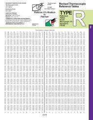
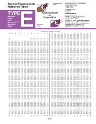
can be obtained by reading the voltmeter and consulting<br />
the National Bureau of Standards Thermocouple<br />
Tables 3 in Section T of the OMEGA TEMPERATURE<br />
MEASUREMENT HANDBOOK - see Table 3.<br />
T = a 0 +a 1 x + a 2 x 2 + a 3 x 3 ...+a n x n<br />
where<br />
T = Temperature<br />
x = Thermocouple EMF in Volts<br />
a = Polynomial coefficients unique to each<br />
thermocouple<br />
n = Maximum order of the polynomial<br />
As n increases, the accuracy of the polynomial<br />
improves. A representative number is n = 9 for ± 1ºC<br />
accuracy. Lower order polynomials may be used over a<br />
narrow temperature range to obtain higher system<br />
speed.<br />
Table 4 is an example of the polynomials used to<br />
convert voltage to temperature. Data may be utilized in<br />
packages for a data acquisition system. Rather than<br />
directly calculating the exponentials, the computer is<br />
programmed to use the nested polynomial form to save<br />
execution time. The polynomial fit rapidly degrades<br />
outside the temperature range shown in Table 4 and<br />
should not be extrapolated outside those limits.<br />
Z-25<br />
Millivolts<br />
80<br />
60<br />
40<br />
20<br />
0°<br />
E<br />
J<br />
K<br />
R<br />
S<br />
500° 1000° 1500° 2000°<br />
Temperature °C<br />
Type<br />
E<br />
J<br />
K<br />
R<br />
S<br />
T<br />
Metals<br />
+ –<br />
Chromel vs. Constantan<br />
Iron vs. Constantan<br />
Chromel vs. Alumel<br />
Platinum vs. Platinum<br />
13% Rhodium<br />
Platinum vs. Platinum<br />
10% Rhodium<br />
Copper vs. Constantan<br />
THERMOCOUPLE TEMPERATURE<br />
vs.<br />
VOLTAGE GRAPH<br />
Figure 16