LNG ship to ship bunkering procedure - Svenskt Marintekniskt Forum
LNG ship to ship bunkering procedure - Svenskt Marintekniskt Forum
LNG ship to ship bunkering procedure - Svenskt Marintekniskt Forum

Create successful ePaper yourself
Turn your PDF publications into a flip-book with our unique Google optimized e-Paper software.
<strong>LNG</strong> <strong>bunkering</strong> Ship <strong>to</strong> Ship <strong>procedure</strong><br />
<strong>LNG</strong> <strong>bunkering</strong> Ship <strong>to</strong> Ship<br />
<strong>LNG</strong> <strong>ship</strong> <strong>to</strong> <strong>ship</strong> <strong>bunkering</strong> <strong>procedure</strong><br />
Swedish Marine Technology <strong>Forum</strong> | Linde Cryo AB | FKAB Marine Design<br />
Det Norske Veritas AS | <strong>LNG</strong> GOT | White Smoke AB
<strong>LNG</strong> <strong>bunkering</strong> Ship <strong>to</strong> Ship <strong>procedure</strong><br />
<strong>LNG</strong> <strong>bunkering</strong> Ship <strong>to</strong> Ship <strong>procedure</strong><br />
Swedish Marine Technology <strong>Forum</strong> | Linde Cryo AB | FKAB Marine Design<br />
Det Norske Veritas AS | <strong>LNG</strong> GOT | White Smoke AB
<strong>LNG</strong> <strong>bunkering</strong> Ship <strong>to</strong> Ship <strong>procedure</strong><br />
Copyright © Swedish Marine Technology <strong>Forum</strong><br />
Publisher<br />
Print No<br />
Swedish Marine Technology <strong>Forum</strong><br />
Museigatan 2, 3rd floor. SE- 451 50 UDDEVALLA<br />
Phone: + 46 522-199 32 | Email: info@smtf.se | Web: www.smtf.se<br />
<strong>LNG</strong>02<br />
Swedish Marine Technology <strong>Forum</strong> funding through member companies and
<strong>LNG</strong> <strong>bunkering</strong> Ship <strong>to</strong> Ship <strong>procedure</strong><br />
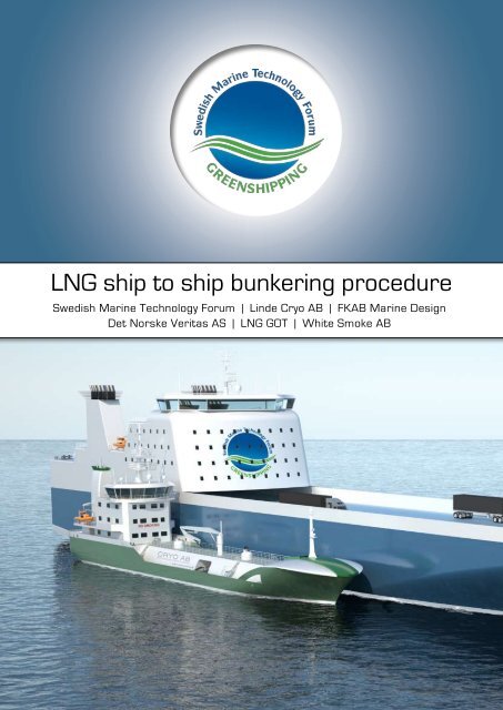
Summary<br />
This document is a procedural description of how <strong>LNG</strong> (liquid natural gas) <strong>bunkering</strong> between two <strong>ship</strong>s<br />
should be done.<br />
The document is the result of the joint venture project “<strong>LNG</strong> <strong>bunkering</strong> Ship <strong>to</strong> Ship”, a technology<br />
development project carried out by Swedish Marine Technology <strong>Forum</strong>, FKAB Marine Design,<br />
Linde Cryo AB, Det Norske Veritas AS (DNV), <strong>LNG</strong> GOT and White Smoke AB.<br />
<strong>LNG</strong> <strong>bunkering</strong> <strong>ship</strong> <strong>to</strong> <strong>ship</strong> in port with demands for short operation time have not been performed before<br />
and this <strong>procedure</strong> has been worked out <strong>to</strong> handle the specific details of this operation in a safe way.<br />
The <strong>procedure</strong> is made for <strong>ship</strong> <strong>to</strong> <strong>ship</strong> <strong>bunkering</strong> of <strong>LNG</strong> in a port environment, with a dedicated bunker<br />
<strong>ship</strong> rapidly delivering the fuel <strong>to</strong> client <strong>ship</strong>s while cargo and passenger handling is still in progress.<br />
The project has developed a <strong>LNG</strong> <strong>bunkering</strong> concept that encompasses both the operational <strong>bunkering</strong><br />
process and technical solutions needed for <strong>ship</strong> <strong>to</strong> <strong>ship</strong> <strong>bunkering</strong> of <strong>LNG</strong>.<br />
The conclusion of this study is that <strong>LNG</strong> <strong>bunkering</strong> <strong>ship</strong> <strong>to</strong> <strong>ship</strong> is indeed a suitable solution <strong>to</strong> provide<br />
environmentally friendly bunker fuel <strong>to</strong> larger <strong>ship</strong>s.<br />
The concept is accepted and approved in principle by DNV.<br />
5
<strong>LNG</strong> <strong>bunkering</strong> Ship <strong>to</strong> Ship <strong>procedure</strong><br />
6
<strong>LNG</strong> <strong>bunkering</strong> Ship <strong>to</strong> Ship <strong>procedure</strong><br />
Table of content<br />
Summary .........................................................................................................................................................5<br />
Project Members.....................................................................................................................................................12<br />
The Working group..................................................................................................................................................12<br />
The Reference group..............................................................................................................................................13<br />
Background ......................................................................................................................................................14<br />
Project objectives.....................................................................................................................................................16<br />
Approval in principle by DNV...............................................................................................................................17<br />
Project Method ......................................................................................................................................................18<br />
Rules and Guidelines...............................................................................................................................................18<br />
The Results ......................................................................................................................................................19<br />
Preface – <strong>LNG</strong> <strong>bunkering</strong> <strong>ship</strong> <strong>to</strong> <strong>ship</strong> <strong>procedure</strong>.................................................................................. 21<br />
Bunkering Timeline...................................................................................................................................................22<br />
Glossary ......................................................................................................................................................23<br />
1 GENERAL PRINCIPLES..............................................................................................................................24<br />
1.1 Scope ......................................................................................................................................................24<br />
1.2 Control of operations..........................................................................................................................24<br />
1.3 Responsibility..........................................................................................................................................24<br />
2 CONDITIONS AND REQUIREMENTS.................................................................................................25<br />
2.1 Approval....................................................................................................................................................25<br />
2.2 Ship Compatibility.................................................................................................................................25<br />
2.3 Transfer Area........................................................................................................................................25<br />
2.4 Weather Conditions............................................................................................................................25<br />
2.5 Light Conditions.....................................................................................................................................25<br />
3 SAFETY ......................................................................................................................................................26<br />
3.1 General ......................................................................................................................................................26<br />
3.2 EX-Zone.....................................................................................................................................................26<br />
3.3 ESD-System.............................................................................................................................................26<br />
3.4 Check-Lists..............................................................................................................................................26<br />
3.5 Instructions (Routines)......................................................................................................................26<br />
3.6 Warning signs.......................................................................................................................................26<br />
3.7 Safety during Bunker..........................................................................................................................27<br />
3.7.1 Smoking and Naked Light................................................................................................27<br />
3.7.2 Earth on switchboard........................................................................................................27<br />
3.7.3 Electrical Currents..............................................................................................................27.<br />
3.7.4 Radio and Communication Equipment......................................................................27<br />
7
<strong>LNG</strong> <strong>bunkering</strong> Ship <strong>to</strong> Ship <strong>procedure</strong><br />
3.7.5 Radar.........................................................................................................................................28<br />
3.7.6 Electrical s<strong>to</strong>rms..................................................................................................................28<br />
3.7.7 Fire-Fighting Equipment....................................................................................................28<br />
3.7.8 Accommodation Openings..............................................................................................28<br />
3.7.9 Safety Zone.............................................................................................................................28<br />
3.7.10 Gas Accumulation...............................................................................................................28<br />
3.8 Maintenance...........................................................................................................................................28<br />
3.9 Redundancy............................................................................................................................................28<br />
3.10 Personnel education and training..............................................................................................29<br />
3.11 Personal protection equipment ..................................................................................................29<br />
3.12 Sharp edges.........................................................................................................................................29<br />
4 COMMUNICATIONS....................................................................................................................................30<br />
4.1 Language..................................................................................................................................................30<br />
4.2 Communication between Ships.....................................................................................................30<br />
4.3 Procedure for Communication Failure ......................................................................................30<br />
5 OPERATIONS BEFORE BUNKERING..................................................................................................31<br />
5.1 Preparations...........................................................................................................................................31<br />
5.1.1 <strong>LNG</strong> Tank System Check................................................................................................................31<br />
5.1.2 Mooring Equipment Check............................................................................................................31<br />
5.1.3 Bunker Hose Check..........................................................................................................................31<br />
5.1.4 Oil Bunkering........................................................................................................................................31<br />
5.2 Check-List Before Bunker.................................................................................................................31<br />
5.3 Call ......................................................................................................................................................32<br />
5.3.1 Safe Communication..........................................................................................................32<br />
5.3.2 Mooring Plan.........................................................................................................................32<br />
5.4 Manoeuvring...........................................................................................................................................32<br />
5.5 Mooring.....................................................................................................................................................32<br />
5.5.1 Fender Positioning..............................................................................................................32<br />
5.5.2 Fender Type and Size.........................................................................................................32<br />
5.5.3 Mooring Operation..............................................................................................................32<br />
5.5.4 Mooring Lines Supervision..............................................................................................33<br />
5.6 Connection Communication Link (Option).................................................................................33<br />
5.7 Connection of Hoses...........................................................................................................................33<br />
5.8 Bunker Hoses........................................................................................................................................34<br />
5.8.1 <strong>LNG</strong> Bunker Hose and Vapour Return Hose..........................................................34<br />
5.8.2 Oil Bunker Hose....................................................................................................................34<br />
5.9 Pre-Transfer Bunker Check List....................................................................................................34<br />
8
<strong>LNG</strong> <strong>bunkering</strong> Ship <strong>to</strong> Ship <strong>procedure</strong><br />
6 OPERATIONS DURING BUNKERING .................................................................................................35<br />
6.1 Return of Documents.........................................................................................................................35<br />
6.1.1 Signed Check-List.................................................................................................................35<br />
6.1.2 Signed document with Agreed Amount and Transfer Rate............................35<br />
6.2 Open Manual Bunker Valves...........................................................................................................35<br />
6.3 Ready Signal Both Ships...................................................................................................................35<br />
6.4 Pump Start Sequence........................................................................................................................35<br />
6.5 Bunkering.................................................................................................................................................36<br />
6.6 Pump S<strong>to</strong>p Sequence.........................................................................................................................36<br />
7 OPERATIONS AFTER BUNKERING.....................................................................................................37<br />
7.1 Purging of Bunker Hoses.................................................................................................................37<br />
7.2 Close Manual and Remote controlled valves..........................................................................37<br />
7.3 Disconnection of Hoses....................................................................................................................37<br />
7.4 Disconnection Communication Link (Option)...........................................................................38<br />
7.5 Delivery Bunker Document..............................................................................................................38<br />
7.6 Unmooring...............................................................................................................................................38<br />
7.7 Manoeuvring...........................................................................................................................................38<br />
7.8 Inerting of Bunker Lines....................................................................................................................38<br />
7.9 Check-list After Bunker......................................................................................................................38<br />
8 EQUIPMEN ......................................................................................................................................................39<br />
8.1 Bunker Hoses........................................................................................................................................39<br />
8.1.1 Hose Standards...................................................................................................................39<br />
8.1.2 Hose Size and Length........................................................................................................39<br />
8.1.3 Hose Handling.......................................................................................................................39<br />
8.1.4 Hose Connection..................................................................................................................39<br />
8.1.5 Hose Inspection and Testing..........................................................................................39<br />
8.1.6 Marking....................................................................................................................................39<br />
8.1.7 Differential Pressure Measuring..................................................................................39<br />
8.2 Bunker Station (Receiving <strong>ship</strong>).....................................................................................................40<br />
8.3 Break-away Coupling...........................................................................................................................41<br />
8.4 Mooring Equipment.............................................................................................................................41<br />
8.5 Personnel Transfers...........................................................................................................................41<br />
8.6 Lighting ......................................................................................................................................................41<br />
8.7 Trays below manifolds........................................................................................................................41<br />
8.8 Gas Detec<strong>to</strong>rs .......................................................................................................................................41<br />
8.9 Fuel Quality Measuring (Option)....................................................................................................41<br />
9
<strong>LNG</strong> <strong>bunkering</strong> Ship <strong>to</strong> Ship <strong>procedure</strong><br />
9 <strong>LNG</strong> CARGO SYSTEM DESCRIPTION................................................................................................42<br />
9.1 General ......................................................................................................................................................42<br />
9.2 Equipment................................................................................................................................................42<br />
9.2.1 General data..........................................................................................................................42<br />
9.2.2 Tanks.........................................................................................................................................42<br />
9.2.3 Pumps.......................................................................................................................................43<br />
9.2.4 Bunker Stations (System)................................................................................................43<br />
9.2.5 Piping System........................................................................................................................43<br />
9.2.6 Vacuum Insulated Pipes...................................................................................................44<br />
9.2.7 Double Trunk Pipes ...........................................................................................................44<br />
9.2.8 Safety Valves..........................................................................................................................44<br />
9.2.9 Vent Mast................................................................................................................................44<br />
9.2.10 ESD System............................................................................................................................44.<br />
9.3 Process.....................................................................................................................................................45<br />
10 ESD PHILOSOPHY........................................................................................................................................46<br />
10.1 Reference..............................................................................................................................................46<br />
10.2 ESD Analysis.........................................................................................................................................46<br />
10.3 The Receiving <strong>ship</strong>.............................................................................................................................46<br />
10.4 The Bunker <strong>ship</strong>..................................................................................................................................46<br />
10.5 Transfer Interface when Bunkering..........................................................................................47<br />
10.6 ESD Philosophy....................................................................................................................................48<br />
11 EMERGENCY OPERATIONS....................................................................................................................49<br />
11.1 Emergency Signal...............................................................................................................................49<br />
11.2 State of Readiness for an Emergency......................................................................................49<br />
11.3 Contingency Planning.......................................................................................................................49<br />
11.4 Emergency Situations......................................................................................................................50<br />
11.5 Safety Drills...........................................................................................................................................50<br />
11.6 Advice on some Emergencies......................................................................................................50<br />
11.6.1 Emergencies during Manoeuvring..............................................................................50<br />
11.6.2 Procedures for Communication Failure...................................................................50<br />
11.6.3 Activation of Emergency Shut-Down Systems (ESD)..........................................50<br />
11.6.4 Procedures for Leakage / Gas Accumulation......................................................51<br />
11.6.5 Accidental <strong>LNG</strong> Bunker Fuel Release ........................................................................51<br />
11.6.6 Accidental Oil Bunker Fuel Release and Oil Pollution Control.........................51<br />
10
<strong>LNG</strong> <strong>bunkering</strong> Ship <strong>to</strong> Ship <strong>procedure</strong><br />
12 GAS HANDLING.............................................................................................................................................52<br />
12.1 General....................................................................................................................................................52<br />
12.2 Safety Information .............................................................................................................................52<br />
12.2.1 Cryogenic Liquids.................................................................................................................52<br />
12.2.2 Risks when inhaling Methane (CH4) Natural Gas................................................52<br />
12.2.3 Risks when inhaling Nitrogen (N2) Gas....................................................................52<br />
12.2.4 Fire..............................................................................................................................................53<br />
12.2.5 Risks when in contact with Cold items and Gas...................................................53<br />
12.2.6 Personal Protection...........................................................................................................53<br />
12.2.7 Vapour Fog, Mist..................................................................................................................53<br />
12.2.8 Trapped Liquid ......................................................................................................................53<br />
12.2.9 Training.....................................................................................................................................54<br />
References ......................................................................................................................................................55<br />
Appendix A CHECK-LIST BEFORE BUNKERING..............................................................................56<br />
Appendix B CHECK-LIST PRE-TRANSFER..........................................................................................57<br />
Appendix C CHECK-LIST AFTER BUNKERING.................................................................................59<br />
Appendix D – Flow Diagram <strong>LNG</strong> Ship <strong>to</strong> Ship <strong>bunkering</strong>........................................................60<br />
Appendix E – <strong>LNG</strong> Cargo System P&ID.............................................................................................61<br />
11
<strong>LNG</strong> <strong>bunkering</strong> Ship <strong>to</strong> Ship <strong>procedure</strong><br />
Project Members<br />
The joint industry project consists of two main groups: The working group and the reference group. This project is funded<br />
by the members in the working group.<br />
The Working group<br />
The working group consists of six different companies: Swedish Marine Technology <strong>Forum</strong>, Linde Cryo AB, FKAB Marine<br />
Design, <strong>LNG</strong> GOT, White Smoke AB.<br />
Swedish Marine Technology <strong>Forum</strong> is a non-profit organization that gathers the maritime industry in Sweden.The organization<br />
is working <strong>to</strong>ward development of new and less environmentally damaging products, efficient production and cooperation<br />
between firms, universities and public representatives. Swedish Marine Technology <strong>Forum</strong> is also working <strong>to</strong> increase<br />
recruitment and enhance regeneration in the maritime industry.<br />
The forum brings <strong>to</strong>gether the entire maritime industry in Sweden and its future challenges. The forum is addressed <strong>to</strong> the<br />
companies that is suppliers for the <strong>ship</strong>ping, offshore and the leisure boat industry. Our members are engineering solutions,<br />
manufacturing, products and services in these areas.<br />
Linde Cryo AB is one of the world’s leading manufacturers of cryogenic equipment for the s<strong>to</strong>rage, transportation and handling<br />
of liquefied gases. We are an independent company belonging <strong>to</strong> the Linde Engineering Division. For more than 50 years<br />
we have put our skills and advanced technology at the service of the gas industry.<br />
We are a speaking partner for most industrial gas companies when it comes <strong>to</strong> selecting the most efficient and economical<br />
cryogenic equipment.<br />
CRYO AB is certified manufacturer of cryogenic pressure vessels with production according <strong>to</strong> several national and international<br />
approvals and standards, e.g. DNV, CE, ASME, ISO 9001.<br />
CRYO AB’s product line includes a large variety of <strong>LNG</strong> equipment, both on-shore and off-shore. The company’s <strong>LNG</strong> programme<br />
includes complete <strong>LNG</strong> receiving terminals, semi-trailer for land transport, fuel tanks for <strong>ship</strong>s and ferries, as well as<br />
gas supply back-up systems and mobile equipment for the testing of gas turbines.<br />
Regarding <strong>LNG</strong> propellant systems for <strong>ship</strong>s, CRYO AB has delivered more than 20 <strong>LNG</strong> fuel tanks with sufficient equipment<br />
in accordance with class rules. Ship types with these systems have been road ferries, PSV’s and coast guard vessels.<br />
FKAB Marine Design is a well recognized international consultancy firm who has delivered successful <strong>ship</strong> designs <strong>to</strong> <strong>ship</strong><br />
owners and <strong>ship</strong>yards since 1961.<br />
Our experience makes us an innovative and reliable design partner for any type of <strong>ship</strong> from the first sketch on a paper <strong>to</strong><br />
complete production drawings.<br />
In our portfolio of proven <strong>ship</strong> designs you find a great variety of designs ranging from a 6 m unmanned cable ferry <strong>to</strong> a 174<br />
000 DWT cape size bulk carrier. We also supply our cus<strong>to</strong>mers with all types of marine design related engineering services such<br />
as conversion design, <strong>ship</strong> stability, structural design, feasibility studies, project management, <strong>ship</strong>yard evaluations etc.<br />
FKAB Marine Design - serving clients World Wide.<br />
12
<strong>LNG</strong> <strong>bunkering</strong> Ship <strong>to</strong> Ship <strong>procedure</strong><br />
<strong>LNG</strong> GOT, owned by Gasnor and Göteborg Energi, introduces <strong>LNG</strong> (liquefied natural gas) as fuel for <strong>ship</strong>s in the port of<br />
Gothenburg. The goal is <strong>to</strong> deliver <strong>LNG</strong> from 2013.<br />
Over the next decade significantly stringent environmental rules are expected for <strong>ship</strong>ping. The emissions will be reduced<br />
significantly and it demands new alternative fuel for <strong>ship</strong>ping. <strong>LNG</strong> is a very interesting alternative <strong>to</strong> current <strong>ship</strong> fuel. <strong>LNG</strong><br />
reduces emissions dramatically compared <strong>to</strong> for example heavy fuel oil.<br />
White Smoke AB is founded on the belief that developed <strong>ship</strong>ping is an important and necessary part of the solution for the<br />
change in<strong>to</strong> a more sustainable society. The company is a combined business development and consultancy company developing<br />
sound sustainable <strong>ship</strong>ping business cases on its own behalf as well as for external clients. As a client <strong>to</strong> White Smoke AB<br />
you get an innovative and flexible business partner with profound knowledge how <strong>to</strong> create <strong>ship</strong>ping solutions that combine<br />
“state of the art” environmental performance with a competitive cost level. White Smoke AB is also main owner of White<br />
Smoke Shipping AB, a recently established <strong>ship</strong>ping company based on the same belief as White Smoke AB.<br />
DNV is a global provider of services for managing risk, helping cus<strong>to</strong>mers <strong>to</strong> safely and responsibly improve their business<br />
performance. As companies <strong>to</strong>day are operating in an increasingly more complex and demanding risk environment, DNV’s<br />
core competence is <strong>to</strong> identify, assess, and advise on how <strong>to</strong> manage risk. Its technology expertise and industry knowledge,<br />
combined with its risk management approach, have been used <strong>to</strong> manage the risks involved in numerous high-profile projects<br />
around the world.<br />
Organised as an independent, au<strong>to</strong>nomous foundation, DNV balances the needs of business and society, based on its independence<br />
and integrity. With its objective of safeguarding life, property and the environment, DNV serves a range of industries,<br />
with a special focus on the maritime and energy sec<strong>to</strong>rs. Established in 1864, the company has a global presence with a network<br />
of 300 offices in 100 countries, and is headquartered in Oslo, Norway. Its prime assets are the knowledge and expertise of its<br />
8,000 employees from 98 nations.<br />
The Reference group<br />
Members of the reference group were specially invited in order <strong>to</strong> give best possible input <strong>to</strong> the project. The Reference<br />
group where summoned at certain occasions, such as workshops, reviews and presentations.<br />
Reference group member companies are as follows:<br />
Viking Line ABP<br />
Göteborgs Hamn<br />
Stena AB<br />
Topoil AB<br />
Fjordtank Rederi AB<br />
I M Skaugen<br />
SSPA Sweden AB<br />
Gasföreningen<br />
Transportstyrelsen<br />
Myndigheten för Samhällskydd och Beredskap<br />
13
<strong>LNG</strong> <strong>bunkering</strong> Ship <strong>to</strong> Ship <strong>procedure</strong><br />
Background<br />
Our globe requires sustainable <strong>ship</strong>ping and cus<strong>to</strong>mers and cargo owners are demanding more environmentally<br />
sound transports. New regulations regarding <strong>ship</strong> emissions are at the horizon. Actions soon<br />
need <strong>to</strong> be taken; the question is only which direction <strong>to</strong> choose.<br />
<strong>LNG</strong> (Liquid Natural Gas) as <strong>ship</strong> fuel is a good option <strong>to</strong> meet future regulations regarding SOx and<br />
NOx emissions set up by international authorities. In 2015 the allowed SOx (Sulphur oxides) emissions<br />
from <strong>ship</strong>s sailing within ECA (Emission Control Area) will drastically be reduced. Since the sulphur<br />
comes purely out of the fuel, a change of fuel away from high sulphur fuels or a change <strong>to</strong> <strong>LNG</strong> will solve<br />
this problem. Low sulphur fuels will then most probably be more sought after and therefore possibly more<br />
costly, which will make <strong>LNG</strong> even more interesting as bunker fuel.<br />
Then in 2016 the new NOx rules are put in<strong>to</strong> force by the IMO (International Maritime Organization),<br />
which means very low levels of NOx emissions are allowed, the so called Tier III levels. This regulation<br />
only concerns <strong>ship</strong>s built after the new regulations are put in<strong>to</strong> force. With <strong>LNG</strong> as fuel it is possible <strong>to</strong><br />
comply with these rules.<br />
The environmental benefits of <strong>LNG</strong> are even higher than the aforementioned requirements. Today, particle<br />
and carbon dioxide emissions are not regulated for <strong>ship</strong>ping. There are though many indications<br />
that restrictions will be introduced even in this area which makes <strong>LNG</strong> an even better alternative fuel for<br />
<strong>ship</strong>ping. Since natural gas has the same components as biogas (a form of natural gas produced from renewable<br />
products), it is possible <strong>to</strong> switch <strong>LNG</strong> for LBG (Liquid Bio Gas). <strong>LNG</strong> can therefore also serve<br />
as a bridge <strong>to</strong> more use of renewable LBG.<br />
Pictures from Gasnor<br />
14
<strong>LNG</strong> <strong>bunkering</strong> Ship <strong>to</strong> Ship <strong>procedure</strong><br />
With <strong>LNG</strong> or LBG as <strong>ship</strong> fuel, there will be almost no emissions of SOx (sulphur oxides) and particles,<br />
very low emissions of NOx (nitrogen oxide) and reduced emissions of CO2 (carbon dioxide). If LBG is<br />
used the CO2 net value levels are very low.<br />
<strong>LNG</strong> is a new product for us in Sweden and a distribution network is not currently structured. However,<br />
an intermediate s<strong>to</strong>rage facility for <strong>LNG</strong> is under construction in the S<strong>to</strong>ckholm region and there are also<br />
plans for a similar <strong>LNG</strong> terminal in the Göteborg harbour.<br />
<strong>LNG</strong> as bunker fuel is not a new invention though; <strong>to</strong>day <strong>LNG</strong> is used as main propulsion fuel for<br />
some Nowegian ferries and offshore vessels. The <strong>bunkering</strong> is done by truck or directly from a shore<br />
based teminal, a proven technology that works well in Norway. This is not an alternative for larger <strong>ship</strong>s<br />
though, where the <strong>LNG</strong> volumes are <strong>to</strong>o large and the supply from a tanker truck would be <strong>to</strong>o timeconsuming.<br />
A build-up of an <strong>LNG</strong> supply chain based on <strong>ship</strong> <strong>to</strong> <strong>ship</strong> <strong>bunkering</strong> instead is therefore of paramount<br />
importance for <strong>LNG</strong> <strong>to</strong> become a real alternative <strong>to</strong> Heavy Fuel oil and other bunker fuels. Nevertheless,<br />
there are no existing international guidelines for the <strong>procedure</strong> of <strong>ship</strong> <strong>to</strong> <strong>ship</strong> <strong>bunkering</strong> of <strong>LNG</strong> <strong>to</strong>day.<br />
This lack of formalities formed the project “<strong>LNG</strong> <strong>bunkering</strong> <strong>ship</strong> <strong>to</strong> <strong>ship</strong>” in order <strong>to</strong> develop an operational<br />
<strong>bunkering</strong> process and the technical solutions needed. The project is initiated by <strong>Svenskt</strong> <strong>Marintekniskt</strong><br />
<strong>Forum</strong> and carried out <strong>to</strong>gether with FKAB Marine Design, Linde Cryo AB, Det Norske Veritas AS<br />
(DNV), <strong>LNG</strong> GOT and White Smoke AB.<br />
<strong>LNG</strong> <strong>bunkering</strong><br />
15
<strong>LNG</strong> <strong>bunkering</strong> Ship <strong>to</strong> Ship <strong>procedure</strong><br />
Project objectives<br />
This project aims at establishing a safe and time efficient <strong>ship</strong> <strong>to</strong> <strong>ship</strong> <strong>bunkering</strong> <strong>procedure</strong> for <strong>LNG</strong>,<br />
encompassing the entire <strong>bunkering</strong> operation, both the operational <strong>bunkering</strong> process and the technical<br />
solutions needed.<br />
Since there are no existing guidelines for <strong>LNG</strong> <strong>bunkering</strong> <strong>ship</strong> <strong>to</strong> <strong>ship</strong>, the project will try <strong>to</strong> establish<br />
a foundation for an international standard and accompanying guideline for safe and time efficient<br />
<strong>bunkering</strong> of <strong>LNG</strong>.<br />
The main objective of this project is for the outcome <strong>to</strong> be accepted and approved in principal by DNV.<br />
Approval in principle by DNV, page 13<br />
16<br />
<strong>LNG</strong> <strong>bunkering</strong>
<strong>LNG</strong> <strong>bunkering</strong> Ship <strong>to</strong> Ship <strong>procedure</strong><br />
17
<strong>LNG</strong> <strong>bunkering</strong> Ship <strong>to</strong> Ship <strong>procedure</strong><br />
Project Method<br />
The bunker scenario<br />
The Ro-Pax vessel sailing in short sea <strong>ship</strong>ping is highlighted as a suitable user of <strong>LNG</strong> as main fuel. The<br />
<strong>bunkering</strong> of such a <strong>ship</strong> is used as reference throughout this project.<br />
It is assumed that the <strong>bunkering</strong> will take place in a port very close <strong>to</strong> urban areas and that the Ro-Pax<br />
<strong>ship</strong> has short turnaround time, approximately one hour. This means that the requirements on the <strong>ship</strong> <strong>to</strong><br />
<strong>ship</strong> <strong>bunkering</strong> are strict both for <strong>bunkering</strong> speed as well as for safety aspects.<br />
For a Ro-Pax <strong>ship</strong> the time schedule is of most importance. Therefore, in order not <strong>to</strong> prolong the stay in<br />
port, the <strong>bunkering</strong> operation has <strong>to</strong> be carried out during unloading and loading.<br />
In most cases the <strong>LNG</strong> fuelled <strong>ship</strong> will need both <strong>LNG</strong> and some type of diesel oil for propulsion. Either<br />
the <strong>ship</strong> has both pure gas engines and pure diesel engines for redundancy issues. Either the <strong>ship</strong> uses<br />
dual-fuel engines, an engine that uses small amounts of diesel <strong>to</strong> ignite the gas. In both cases <strong>LNG</strong> and<br />
diesel oil are used as bunker fuels. Focus has been on providing both bunker fuels at the same time from<br />
one bunker <strong>ship</strong>.<br />
The amount of <strong>LNG</strong> bunker fuel needed for this scenario is set <strong>to</strong> 130 m3 = 65 <strong>to</strong>n. The maximum <strong>bunkering</strong><br />
time including mooring is set <strong>to</strong> 50 minutes.<br />
For other types of <strong>ship</strong>s on different routes other amounts are of course needed.<br />
Risk Assessment<br />
Safety is of great importance for the use of <strong>LNG</strong> as bunker fuel. As a point of departure the project group<br />
carried out a hazard identification workshop (HAZID) led by DNV. The working group as well as the reference<br />
group participated in the workshop. The HAZID workshop identified the different risks that should<br />
be accounted for and taken care of during a <strong>LNG</strong> <strong>ship</strong> <strong>to</strong> <strong>ship</strong> <strong>bunkering</strong> <strong>procedure</strong>. Since this workshop<br />
was conducted early in the project phase, its outcome served as input <strong>to</strong> the concept development.<br />
The purpose of this exercise was <strong>to</strong> identify additional risks by using <strong>LNG</strong> in a port environment. Each<br />
identified risk was rated by frequency and consequence and documented with comments regarding operational<br />
and technical solutions.<br />
When the HAZID was completed and the report delivered from DNV the risk assessment work started<br />
along with the concept study. During the risk assessment work new risks that came up were added and<br />
taken care of. All risks addressed were accounted for and actions how <strong>to</strong> handle these are directly implemented<br />
in the <strong>bunkering</strong> <strong>procedure</strong> and the technical concept development.<br />
In order <strong>to</strong> achieve the complete risk identification for <strong>LNG</strong> <strong>bunkering</strong> in a certain harbour a complete<br />
risk assessment for the harbour needs <strong>to</strong> be conducted. The risk assessment of this project could serve as<br />
input for such an investigation.<br />
Rules and Guidelines<br />
During <strong>bunkering</strong> there are certain regulations <strong>to</strong> consider. Local authorities and the responsible port<br />
need <strong>to</strong> permit <strong>LNG</strong> <strong>bunkering</strong> at the chosen location. In this study the following national rules and<br />
guidelines has been used:<br />
• Port Regulations for the Port of Göteborg<br />
• Sea Regulations from the Swedish Transport Agency, Maritime department<br />
• Land Regulations from the Swedish Civil Contingencies Agency (MSB)<br />
For the two <strong>ship</strong>s involved in the <strong>bunkering</strong> operation there are two set of rules:<br />
18
<strong>LNG</strong> <strong>bunkering</strong> Ship <strong>to</strong> Ship <strong>procedure</strong><br />
• IMO IGC Code – (International Gas Code), Rules for the bunker <strong>ship</strong><br />
• IMO IGF Interim guidelines – (International Gas Fuel), Rules for the receiving <strong>ship</strong><br />
The IMO IGC Code is the international regulation for gas carriers and will therefore be valid for the bunker<br />
<strong>ship</strong>. For the receiving vessel, the <strong>ship</strong> using <strong>LNG</strong> as bunker fuel, the IGF interim guidelines are the<br />
regulations that have <strong>to</strong> be used. The IGF guidelines are called “interim” since they are not yet finalized.<br />
The IGF guidelines will, according <strong>to</strong> plan, be finalized during 2012. Hopefully the content of this work<br />
could supply the IMO via the IGF working group called BLG (Bulk Liquid Gases), with information and<br />
solutions in order <strong>to</strong> implement <strong>bunkering</strong> in the future IGF Code. With international standards about<br />
<strong>ship</strong> <strong>to</strong> <strong>ship</strong> <strong>bunkering</strong>, systems can be more effectively enforced and the <strong>LNG</strong> fuel supply logistics can<br />
be more widely spread.<br />
Ship <strong>to</strong> Ship <strong>bunkering</strong> of <strong>LNG</strong> is a form of <strong>LNG</strong> transfer and therefore SIGGTO, Society of International<br />
Gas Tanker & Terminal opera<strong>to</strong>rs Ltd, guidelines has been considered. The SIGTTO guidelines are focused<br />
on large scale <strong>LNG</strong> transfer from <strong>LNG</strong> carriers, both for transfer <strong>to</strong> terminal and for Ship <strong>to</strong> Ship <strong>LNG</strong><br />
transfer. Though these guidelines are for large scale <strong>LNG</strong>, many of the aspects could be used within the<br />
<strong>LNG</strong> <strong>bunkering</strong> <strong>ship</strong> <strong>to</strong> <strong>ship</strong> project.<br />
The bunker scenario of this study includes transfer of both <strong>LNG</strong> and diesel oil from one <strong>ship</strong> <strong>to</strong> another.<br />
Therefore the SIGGTO as well as the OCIMF, Oil Companies International Marine <strong>Forum</strong>, guidelines<br />
need <strong>to</strong> be accounted for within the work of the study. The set up of the <strong>bunkering</strong> <strong>procedure</strong> described<br />
in the Appendix is based upon the OCIMF guidelines considering oil <strong>bunkering</strong>, in order <strong>to</strong> get an internationally<br />
accepted structure <strong>to</strong> the document.<br />
During the risk assessment and the concept development, DNV has provided the project with vital information<br />
from the class society point of view.<br />
The Results<br />
The main aim with this project has been <strong>to</strong> establish a safe and time efficient <strong>ship</strong> <strong>to</strong> <strong>ship</strong> <strong>bunkering</strong><br />
<strong>procedure</strong> for <strong>LNG</strong>, encompassing the entire <strong>bunkering</strong> operation, with both the operational <strong>bunkering</strong><br />
process and the technical solutions that are needed. The <strong>bunkering</strong> <strong>procedure</strong> presented in the text below<br />
meets this requirement and the complete concept is accepted and approved in principle by DNV.<br />
This procedural description over the <strong>LNG</strong> <strong>ship</strong> <strong>to</strong> <strong>ship</strong> <strong>bunkering</strong> can be used by authorities and others<br />
as input <strong>to</strong> regulation and guideline work concerning <strong>LNG</strong> <strong>bunkering</strong>. The project has already been acknowledged<br />
by Swedish authorities who will use it as input <strong>to</strong> their work. The class society Germanischer<br />
Lloyd (GL) has also showed interest in the project, they will carry on with a similar project called BunGas<br />
which uses the knowledge from the <strong>LNG</strong> <strong>bunkering</strong> <strong>ship</strong> <strong>to</strong> <strong>ship</strong> project.<br />
This study has showed that <strong>LNG</strong> <strong>bunkering</strong> <strong>ship</strong> <strong>to</strong> <strong>ship</strong> is indeed a suitable solution <strong>to</strong> provide environmentally<br />
friendly bunker fuel <strong>to</strong> larger <strong>ship</strong>s which hopefully will open for more utilization of <strong>LNG</strong> or<br />
LBG in <strong>ship</strong>ping.<br />
In order <strong>to</strong> produce a description which was general <strong>to</strong> fit many needs and different <strong>bunkering</strong> cases, certain<br />
technical solutions which have been developed during this project are not included in the <strong>bunkering</strong><br />
<strong>procedure</strong> such as; The hose handling crane and the fact that pumping of <strong>LNG</strong> from the bunker <strong>ship</strong> can<br />
be done without using pumps.<br />
19
<strong>LNG</strong> <strong>bunkering</strong> Ship <strong>to</strong> Ship <strong>procedure</strong><br />
The hose handling crane<br />
Among the first issues that were discussed in the risk assessment, was <strong>LNG</strong> hose handling and the risk for<br />
hose damage. The hose handling needs <strong>to</strong> be very accurate and fast, in order <strong>to</strong> comply with the <strong>bunkering</strong><br />
scenario, therefore a hose handling crane was discussed. The company TTS, which has shown a great<br />
interest <strong>to</strong> this project, promised <strong>to</strong> help us design this hose handling crane.<br />
Picture of TTS Hose Cobra II<br />
This hose crane can handle all hoses described in the <strong>bunkering</strong> <strong>procedure</strong>. The crane connects <strong>to</strong> the hull<br />
side of the receiving <strong>ship</strong> via a vacuum suction system, in that position the hoses are very easily reached<br />
from the bunker port. When the crane is connected <strong>to</strong> the hull side, the hydraulic system is released which<br />
enables the crane <strong>to</strong> follow all <strong>ship</strong> movements.<br />
Pumping of <strong>LNG</strong> using pressure instead of pumps<br />
A <strong>LNG</strong> tank can be emptied using a high pressure inside the tank instead of using a pump. This fact<br />
made CRYO <strong>to</strong> investigate if an increased pressure in the <strong>LNG</strong> cargo tank could transfer the <strong>LNG</strong> at the<br />
same rate as with a normal cryogenic deep-well pump. Technically this is a very interesting solution and<br />
according <strong>to</strong> CRYO, even higher transfer rates can be achieved using the method.<br />
The system demands that both the cargo tank and the receiving bunker tank can handle a high pressure<br />
of approximately 10 bar. There is also an increased risk of unwanted release of methane via the safety<br />
valves due <strong>to</strong> the high pressure. Nevertheless it is a interesting solution which CRYO will investigate more<br />
thoroughly.<br />
20
<strong>LNG</strong> <strong>bunkering</strong> Ship <strong>to</strong> Ship <strong>procedure</strong><br />
Preface – <strong>LNG</strong> <strong>bunkering</strong> <strong>ship</strong> <strong>to</strong> <strong>ship</strong> <strong>procedure</strong><br />
This <strong>procedure</strong> is made for <strong>ship</strong> <strong>to</strong> <strong>ship</strong> <strong>bunkering</strong> of <strong>LNG</strong> in a port environment, with a dedicated bunker<br />
<strong>ship</strong> delivering the fuel <strong>to</strong> client <strong>ship</strong>s. <strong>LNG</strong> <strong>bunkering</strong> <strong>ship</strong> <strong>to</strong> <strong>ship</strong> in port with demands for short<br />
operation time have not been performed before and this <strong>procedure</strong> has been worked out <strong>to</strong> handle the<br />
specific details of this operation in a safe way.<br />
The <strong>procedure</strong> is based on existing guidelines for <strong>LNG</strong> and petroleum <strong>ship</strong>-<strong>to</strong>-<strong>ship</strong> transfers <strong>to</strong>gether with<br />
the result from the HAZID exercise and risk assessment work described above.<br />
This <strong>procedure</strong> is divided in<strong>to</strong> chapters describing different aspects of the process :<br />
• Chapter 1-4 refers <strong>to</strong> conditions for <strong>bunkering</strong> <strong>LNG</strong> and petroleum<br />
• Chapter 5-7 refers <strong>to</strong> the Bunkering process<br />
• Chapter 8-10 refers <strong>to</strong> system and equipment description<br />
• Chapter 11-12 refers <strong>to</strong> emergency operations and Gas handling<br />
The <strong>procedure</strong> is made for both transfer of liquefied gases for propulsion purposes (<strong>LNG</strong>) and petroleum,<br />
simultaneously or one fuel only. The parts of the <strong>procedure</strong> which are specific for <strong>LNG</strong>, or for petroleum,<br />
are clearly marked in the caption <strong>to</strong> each sub-chapter.<br />
This is a general description of a <strong>bunkering</strong> process and can only be used as a guideline for future <strong>bunkering</strong><br />
projects. For dedicated <strong>ship</strong>s there may be additional technical and/or operational solutions which can<br />
enhance safety and shorten the <strong>bunkering</strong> time.<br />
Bunkering <strong>ship</strong> <strong>to</strong> <strong>ship</strong> <strong>to</strong>day<br />
21
<strong>LNG</strong> <strong>bunkering</strong> Ship <strong>to</strong> Ship <strong>procedure</strong><br />
Bunkering Timeline<br />
The timeline used in this project is presented in the picture below.<br />
The time limit for the bunker scenario is set <strong>to</strong> 50 minutes for the complete <strong>bunkering</strong> <strong>ship</strong> <strong>to</strong> <strong>ship</strong><br />
<strong>procedure</strong>. In order <strong>to</strong> more easily distinguish the different actions during the <strong>bunkering</strong> operation the<br />
procedural description is divided in three stages: Before, During and After <strong>bunkering</strong>. These stages are<br />
described more thoroughly in the following text.<br />
<strong>LNG</strong> BUNKERING TIMELINE<br />
TOTAL AVAILABLE BUNKER TIME<br />
50 Min.<br />
EVENT<br />
BEFORE BUNKERING<br />
15 Min.<br />
DURING BUNKERING<br />
25 Min.<br />
AFTER BUNKERING<br />
10 Min.<br />
INERTING<br />
TANK SYSTEM CHECK<br />
EQUIPMENT CHECK<br />
CALL<br />
ARRIVAL<br />
MOORING<br />
CHECKLIST TO RECEIVING SHIP<br />
CONNNECTION LINK / EARTHING<br />
CONNECTION HOSE<br />
RETURN OF SIGNED CHECKLIST<br />
OPEN MANUAL VALVES<br />
READY SIGNAL BOTH SHIPS<br />
PUMP START SEQUENCE<br />
TRANSFER SEQUENCE<br />
PUMP STOP SEQUENCE<br />
PURGING OF CARGO LINES (BOTH SHIPS)<br />
SHUT MANUAL + REMOTE CONTROLLED VALVES<br />
DISCONNECTION HOSES<br />
INERTING OF CARGO LINES (RECEIVING SHIP)<br />
DISCONNECTION LINK / EARTHING<br />
DELIVERY CARGO DOCUMENT<br />
UN-MOORING<br />
DEPARTURE<br />
INERTING OF CARGO LINES (BUNKER SHIP)<br />
Transfer rate = 320 m3/h at 5 m/s<br />
24 min = 130 m3 = 65 <strong>to</strong>nnes<br />
www.fkab.se<br />
22
<strong>LNG</strong> <strong>bunkering</strong> Ship <strong>to</strong> Ship <strong>procedure</strong><br />
Glossary<br />
Bunker Ship<br />
A <strong>ship</strong> which transfers liquefied gases <strong>to</strong> another <strong>ship</strong> for propulsion purposes.<br />
Bunkering Area<br />
Defined area on both <strong>ship</strong>s around <strong>bunkering</strong> station on the receiving <strong>ship</strong> and manifolds on the<br />
bunker <strong>ship</strong>.<br />
ESD<br />
Emergency Shut-Down. The functions of the ESD-system are <strong>to</strong> s<strong>to</strong>p the liquid fuel and vapour flow in<br />
the event of an emergency and <strong>to</strong> bring the bunker handling system <strong>to</strong> a safe static condition.<br />
EX-Zone<br />
Area in which all electrical equipment has increased safety level and the electric energy <strong>to</strong>o low <strong>to</strong> avoid<br />
ignition of <strong>LNG</strong> vapour.<br />
IGC Code<br />
IMO International code for Gas-Carriers<br />
IGF Code (Interim)<br />
IMO International code for Gas-Fuelled <strong>ship</strong>s. Interim version.<br />
IMO<br />
International Maritime Organization.<br />
<strong>LNG</strong><br />
Liquefied Natural Gas. Predominantly methane (CH4) which has been cooled down <strong>to</strong> approx.<br />
-162 deg. C and converted <strong>to</strong> liquid for easier s<strong>to</strong>rage and transportation.<br />
MDO<br />
Marine Diesel Oil is a blended fuel from gasoil and heavy fuel oil.<br />
MGO<br />
Marine Gas Oil is a fuel made from distillates only.<br />
Receiving Ship<br />
A <strong>ship</strong> which receives liquefied gases from another <strong>ship</strong><br />
RPT<br />
Rapid Phase Transition is a phenomenon when <strong>LNG</strong> vaporizes violently in contact with water.<br />
SECA<br />
SOx Emission Control Areas are defined areas with restrictions regarding the amount of sulphur in<br />
the fuel.<br />
Secondary Fenders<br />
Secondary fenders are used for preventing contact between the <strong>ship</strong>s when rolling.<br />
23
<strong>LNG</strong> <strong>bunkering</strong> Ship <strong>to</strong> Ship <strong>procedure</strong><br />
1 GENERAL PRINCIPLES<br />
1.1 Scope<br />
This <strong>procedure</strong> is made for <strong>ship</strong> <strong>to</strong> <strong>ship</strong> <strong>bunkering</strong> of <strong>LNG</strong> in a port environment, with a dedicated bunker<br />
<strong>ship</strong> delivering the fuel <strong>to</strong> client <strong>ship</strong>s. The described bunker operation in this <strong>procedure</strong> is based on<br />
common petroleum and liquefied gas transfers with regards <strong>to</strong> the specific regulations for <strong>LNG</strong> within<br />
IMO IGC codes and interim IGF codes and technical solutions for safe short time <strong>bunkering</strong>.<br />
1.2 Control of operations<br />
On each <strong>ship</strong> there must be one responsible person in charge during the complete bunker operation. This<br />
person is <strong>to</strong> have sufficient education, training and authorization <strong>to</strong> safely perform the <strong>LNG</strong> <strong>bunkering</strong>.<br />
1.3 Responsibility<br />
Each Master is responsible for his own <strong>ship</strong>, personnel and bunker regarding all safety and other issues<br />
for the complete operation. All bunker operations must be agreed upon between the bunker <strong>ship</strong> and the<br />
receiving <strong>ship</strong> before commencing any actions.<br />
<strong>LNG</strong> Bunker Ship (Example)<br />
24
<strong>LNG</strong> <strong>bunkering</strong> Ship <strong>to</strong> Ship <strong>procedure</strong><br />
2 CONDITIONS AND REQUIREMENTS<br />
2.1 Approval<br />
Before commencing any bunker operations it is necessary <strong>to</strong> have Authorities approval for <strong>LNG</strong> <strong>bunkering</strong><br />
and <strong>to</strong> check the local regulations and get approval from the port in which the transfer is planned <strong>to</strong><br />
be carried out.<br />
2.2 Ship Compatibility<br />
It must be clarified that mooring and bunker equipment are compatible in design so that the bunker<br />
operation can be conducted in a safe way before commencing any operations. Following points are <strong>to</strong> be<br />
confirmed by communication :<br />
• Possibility for safe mooring<br />
• The relative freeboard difference (see 6.5 fig.3)<br />
• Type and size of hose connections<br />
• Connection order of the manifolds<br />
Recommendation: Use recommended mooring plan (see 5.3.2) and couplings (see 8.1.4).<br />
2.3 Transfer Area<br />
The transfer area is determined by the local port and approved by authorities (see 2.1). The approaching<br />
bunker <strong>ship</strong> is <strong>to</strong> check and evaluate if the area is suitable for <strong>bunkering</strong> operations. The operation should<br />
be aborted if there are issues that can compromise a safe transfer.<br />
Points <strong>to</strong> be considered are:<br />
• Manoeuvring space<br />
• Tidal conditions<br />
• Traffic density<br />
• Waves, swell and weather conditions (see 2.4)<br />
2.4 Weather Conditions<br />
Weather and current forecast for the area are <strong>to</strong> be studied before commencing <strong>bunkering</strong> operation.<br />
Each Master is responsible for his own <strong>ship</strong> and <strong>bunkering</strong> is only allowed when both Masters agree that<br />
ambient conditions (like wind and weather) are acceptable. Each Master is also responsible <strong>to</strong> determine<br />
restrictions and take actions in case of a sudden change of ambient conditions during a started bunker<br />
transfer.<br />
2.5 Light Conditions<br />
The <strong>bunkering</strong> operation is preferably <strong>to</strong> be conducted during daylight hours.<br />
It is necessary <strong>to</strong> have adequate lighting in case of mooring and <strong>bunkering</strong> operations after daylight hour.<br />
The minimum lighting requirements are the bunker <strong>ship</strong> deck, the receiving <strong>ship</strong> bunker station and the<br />
mooring bollards (see 8.6).<br />
Take notice of weather conditions<br />
25
<strong>LNG</strong> <strong>bunkering</strong> Ship <strong>to</strong> Ship <strong>procedure</strong><br />
3 SAFETY<br />
3.1 General<br />
Each Master is at all time responsible for the bunker operation and should not allow safety issues <strong>to</strong> be<br />
influenced by the actions of others. Each Master is <strong>to</strong> ensure that correct <strong>procedure</strong>s are followed and that<br />
internationally accepted safety standards are maintained and that the <strong>ship</strong> design is according <strong>to</strong> approved<br />
rules and regulations.<br />
3.2 EX-Zone<br />
The <strong>bunkering</strong> areas on both <strong>ship</strong>s are <strong>to</strong> be an EX-classified and restricted area during <strong>bunkering</strong>. Only<br />
authorised personnel is allowed in these areas during <strong>bunkering</strong>. Inside the EX-zone all electrical equipment<br />
requires increased safety level and the electric energy should be <strong>to</strong>o low <strong>to</strong> avoid ignition of <strong>LNG</strong><br />
vapour. The size of the EX-zone shall be according <strong>to</strong> class rules for gas-dangerous space and 10 m horizontally<br />
on each side of the receiving <strong>ship</strong> bunker station + the whole <strong>ship</strong>side vertically.<br />
3.3 ESD-System<br />
Each <strong>ship</strong> is <strong>to</strong> have an independent Emergency Shut-Down system for a quick and safe shut-down in<br />
case of an emergency. The system is described in chapter 10 and 11.6.3.<br />
3.4 Check-Lists<br />
Each <strong>ship</strong> is <strong>to</strong> have internal check-lists for before and after <strong>bunkering</strong>.<br />
For bunker operation there shall be a common check-list which is <strong>to</strong> be filled out and signed by responsible<br />
opera<strong>to</strong>rs on both <strong>ship</strong>s before any operation is commenced.<br />
See 5.2, 5.9, 7.9 and appendix A-C.<br />
3.5 Instructions (Routines)<br />
There shall be written detailed instructions for the <strong>bunkering</strong> process on both <strong>ship</strong>s with regards <strong>to</strong><br />
responsibility and actions <strong>to</strong> be made in case of malfunction or emergency. The instructions are <strong>to</strong> be<br />
quickly available at all times and all personnel involved in <strong>bunkering</strong> operations are <strong>to</strong> be familiar with<br />
the content and location of the instructions. The instructions should cover the following areas:<br />
• Loss of communication or control system (ESD)<br />
• Loss of power<br />
• Safe break-away of <strong>ship</strong>s in case of fire<br />
• Handling of cryogenic and petroleum products including use of personal protection equipment,<br />
ice formation and awareness of sharp edges.<br />
• Waves and weather conditions (see 2.4<br />
3.6 Warning signs<br />
There shall be warning and instruction signs posted around hazardous area on both <strong>ship</strong>s. The signs are <strong>to</strong><br />
be placed clearly visible and according <strong>to</strong> an accepted guideline for placement of warning signs. The warning<br />
signs are <strong>to</strong> cover the risks of handling cryogenic liquid, fire and safety issues and show restricted areas.<br />
26
<strong>LNG</strong> <strong>bunkering</strong> Ship <strong>to</strong> Ship <strong>procedure</strong><br />
3.7 Safety during Bunker<br />
3.7.1 Smoking and Naked Light<br />
Regulations regarding smoking and use of naked light should be strictly enforced. Warning signs and<br />
notices shall be displayed and smoking rooms are <strong>to</strong> be designated and clearly marked.<br />
3.7.2 Earth on switchboard<br />
The main switchboard on the bunker <strong>ship</strong> and the control panel on the receiving <strong>ship</strong> are <strong>to</strong> have earth<br />
indica<strong>to</strong>r lights <strong>to</strong> indicate faulty circuits.<br />
Any indications of faulty circuits are <strong>to</strong> be immediately traced and isolated <strong>to</strong> avoid arcing around<br />
bunker area. The <strong>bunkering</strong> operation is <strong>to</strong> be suspended in case of faulty earth indication during<br />
ongoing transfer.<br />
3.7.3 Electrical Currents<br />
Electrical current and Electrostatic Charge in Bunker Hose<br />
To prevent the occurrence of arcing between the <strong>ship</strong>s the manifolds on both <strong>ship</strong>s are <strong>to</strong> be earthed, all<br />
hoses are <strong>to</strong> be electrically continuous and each hose string shall be fitted with an insulating flange on the<br />
bunker <strong>ship</strong> manifold. It is important that the insulating flange only is fitted <strong>to</strong> one <strong>ship</strong>; otherwise there<br />
may be an electrostatic build-up in the hose between the insulating flanges which can result in arcing.<br />
Electrical Arcing<br />
Other places (besides hose connections) where arcing can occur are:<br />
• Mooring lines (Should be insulated)<br />
• Ladders or gangways between <strong>ship</strong>s (Should be insulated)<br />
• Crane wire runners and hooks (Careful operation)<br />
• Bare wires and chains for fender support (Should be insulated)<br />
3.7.4 Radio and Communication Equipment<br />
The <strong>ship</strong>s main radio transmissions may cause electrical resonance in insulated parts of some <strong>ship</strong> fittings<br />
arcing such as mast stays and this can cause arcing across deck fittings. Radio aerials should be earthed,<br />
but can induce arcing if insula<strong>to</strong>rs are coated with salt, dirt or water. The use of <strong>ship</strong>s main radio equipment<br />
during transfer operations can be dangerous and should be restricted during the process. The equipment<br />
is not <strong>to</strong> be used if there is possibility of flammable gas in the vicinity of the antennas.<br />
Satellite communication equipment normally operates at low power levels and is considered <strong>to</strong> be a low<br />
ignition hazard. The equipment is not <strong>to</strong> be used if there is a possibility for flammable gas in the vicinity<br />
of the antenna.<br />
VHF and UHF communications are low voltage operated and are considered <strong>to</strong> be safe <strong>to</strong> use. Hand-held<br />
VHF or UHF radios are <strong>to</strong> be intrinsically safe (EX-class)<br />
Portable electronic devices such as mobile phones, cameras etc using batteries are not allowed in hazardous<br />
areas unless they are EX-class. It is especially important for personnel working in or visiting such areas<br />
<strong>to</strong> be aware of this.<br />
Warning/notification signs are <strong>to</strong> be posted around these areas.<br />
Recommendation: Use VHF communication (see 4.2 and 5.3)<br />
27
<strong>LNG</strong> <strong>bunkering</strong> Ship <strong>to</strong> Ship <strong>procedure</strong><br />
3.7.5 Radar<br />
The radar equipment is not intrinsically safe and can create potentially hazardous power densities, especially<br />
since the bunker <strong>ship</strong> normally is smaller and the radar will sweep across the receiving <strong>ship</strong> hull at<br />
close range. The radar on the bunker <strong>ship</strong> is <strong>to</strong> be turned off after the mooring sequence and not switched<br />
on before the unmooring sequence starts, unless required by special demands.<br />
3.7.6 Electrical s<strong>to</strong>rms<br />
No bunker operation should be commenced during electrical s<strong>to</strong>rms. In case of sudden electrical s<strong>to</strong>rm<br />
appearance during ongoing transfer, the operation is <strong>to</strong> be suspended and all systems secured until it is<br />
considered safe <strong>to</strong> resume operation.<br />
3.7.7 Fire-Fighting Equipment<br />
Fire-fighting equipment on both <strong>ship</strong>s are <strong>to</strong> be ready for immediate action.<br />
Foam and water moni<strong>to</strong>rs on the bunker <strong>ship</strong> <strong>to</strong> be pointed <strong>to</strong>wards the bunker manifolds in use and the<br />
bunker station fire system should be activated on the receiving <strong>ship</strong>.<br />
3.7.8 Accommodation Openings<br />
All accommodation openings on the bunker <strong>ship</strong> are <strong>to</strong> be closed during transfer.<br />
Personnel transit is only allowed through designated doors which are <strong>to</strong> be closed immediately after use.<br />
Restrictions for receiving <strong>ship</strong> see 3.7.9<br />
3.7.9 Safety Zone<br />
Since the receiving <strong>ship</strong> normally is larger than the bunker <strong>ship</strong> is it important <strong>to</strong> have a safety zone above<br />
the bunker station during <strong>bunkering</strong>. The extent of the safety zone should be 10 metres on each side of<br />
the bunker station manifold.<br />
This safety zone shall be clearly marked and have the following restrictions:<br />
• No unauthorised persons <strong>to</strong> be able <strong>to</strong> access open deck areas directly above the bunker area<br />
• Warning signs <strong>to</strong> be posted around the area<br />
• Access doors <strong>to</strong> be locked and only <strong>to</strong> be opened by trained and authorised personnel<br />
• No overhead crane lifting in this area during <strong>bunkering</strong><br />
• No maintenance work in the area during <strong>bunkering</strong><br />
• No manoeuvring of <strong>ship</strong> equipment in the area during <strong>bunkering</strong><br />
• Ventilation inlets in the area <strong>to</strong> be closed during <strong>bunkering</strong><br />
3.7.10 Gas Accumulation<br />
Transfer operation shall be suspended if there is fuel vapour leaking around manifolds on either <strong>ship</strong>.<br />
Operation is not <strong>to</strong> be resumed until leakage is identified and s<strong>to</strong>pped and all gas has dispersed which is<br />
moni<strong>to</strong>red by gas detec<strong>to</strong>rs at both <strong>ship</strong>s bunker stations (see 8.8).<br />
3.8 Maintenance<br />
Key components in both <strong>ship</strong>s systems are <strong>to</strong> be identified with emphasis on safety <strong>to</strong> avoid leakage and<br />
ignition sources in and around the bunker areas. These components should have a maintenance and replacement<br />
schedule where inspections and actions are documented and s<strong>to</strong>red on board.<br />
3.9 Redundancy<br />
Key components in both <strong>ship</strong>s control and power systems is <strong>to</strong> be identified with emphasis on safety<br />
in case of failure. These components shall have redundancy back-up which can start up within a short<br />
period of time.<br />
28
<strong>LNG</strong> <strong>bunkering</strong> Ship <strong>to</strong> Ship <strong>procedure</strong><br />
Gas-fuelled Ro-Ro Ship (Example)<br />
3.10 Personnel education and training<br />
All personnel working with <strong>LNG</strong> <strong>bunkering</strong> is <strong>to</strong> be educated, trained and authorised for working with<br />
liquefied gases. Non-educated and trained persons are <strong>to</strong> be classified as unauthorised and are therefore<br />
not allowed <strong>to</strong> be inside bunker area during operation. Education and training records of all personnel are<br />
<strong>to</strong> be kept on board and be available if requested by port, authorities or the other <strong>ship</strong>. Regular safety drills<br />
regarding fire, smoke and the handling of loss of communication should be performed and documented<br />
according <strong>to</strong> ISM (International Safety Management) Code 2002 by IMO. (See also 11.5)<br />
3.11 Personal protection equipment<br />
There shall be personal protection equipment, like gloves, eye protec<strong>to</strong>r and protective clothing, for<br />
handling cryogenic products at <strong>bunkering</strong> areas on both <strong>ship</strong>s and the personnel involved are <strong>to</strong> be well<br />
instructed where <strong>to</strong> find the equipment and how <strong>to</strong> use it. There should also be medical treatment facilities<br />
on board and knowledge how <strong>to</strong> handle minor injuries from cryogenic products.<br />
3.12 Sharp edges<br />
Both <strong>ship</strong>s shall be designed not <strong>to</strong> have any sharp edges around the bunker stations due <strong>to</strong> the possibility<br />
<strong>to</strong> damage the hoses during handling. Loose items with potentially sharp edges, like hand <strong>to</strong>ols, are <strong>to</strong> be<br />
s<strong>to</strong>red outside the direct hose handling area.<br />
29
<strong>LNG</strong> <strong>bunkering</strong> Ship <strong>to</strong> Ship <strong>procedure</strong><br />
4 COMMUNICATIONS<br />
4.1 Language<br />
The English language shall be used for communication. Communication phrases should also follow common<br />
standards, for example Standard Marine Communication Phrases (IMO) for the English language.<br />
4.2 Communication between Ships<br />
The communication methods used could be by VHF, hand-held radios, vocally or by a separate communication<br />
link depending on the phase of the operation and availability of equipment. There shall<br />
also be reliable means of communication at all times during mooring and <strong>bunkering</strong>, such as hand-held<br />
VHF. No mooring or transfer operation are <strong>to</strong> begin before effective communication has been confirmed.<br />
Optionally there can be a cable link between the <strong>ship</strong>s containing a wired communication system between<br />
bunker stations (see 5.6)<br />
Recommendation : Use VHF or a communication link (optional) (see 3.7.4 and 5.3)<br />
4.3 Procedure for Communication Failure<br />
Communication failure during approach – Abort approach and re-establish contact before attempting a<br />
new approach.<br />
Communication failure during bunker operations – Sound the emergency signal and suspend all operations<br />
in progress immediately.<br />
Operations shall not be resumed before communications has been re-established.<br />
Communication Equipment (Example)<br />
30
<strong>LNG</strong> <strong>bunkering</strong> Ship <strong>to</strong> Ship <strong>procedure</strong><br />
BUNKER PROCESS CHAPTER 5-7<br />
5 OPERATIONS BEFORE BUNKERING<br />
5.1 Preparations<br />
The following steps shall be made prior <strong>to</strong> start of the operation and noted on the Before bunker check-list:<br />
• Safety zone on receiving <strong>ship</strong> (see 3.7.9) activated and checked.<br />
• Fire equipment on both <strong>ship</strong>s checked and ready for use (see 3.7.7)<br />
• Personal protection equipment on both <strong>ship</strong>s checked and prepared for use (see<br />
12.2.6)<br />
• ESD system on both <strong>ship</strong>s checked and ready for use (see chapter 10)<br />
3.11 and<br />
5.1.1 <strong>LNG</strong> Tank System Check<br />
Both <strong>ship</strong>s must check the <strong>LNG</strong> tanks regarding temperature and pressure prior <strong>to</strong> <strong>bunkering</strong> and note<br />
this on the pre-transfer bunker checklist (see 5.2 and appendix B). If the temperature of the receiving<br />
tank is significantly higher than the bunker tank, there will be an initial vapourisation when starting <strong>to</strong><br />
transfer the <strong>LNG</strong>. This will increase the tank pressure and can trigger the pressure relief valve <strong>to</strong> open if<br />
the pressure exceeds the set limit. The pressure of both tanks must be reduced prior <strong>to</strong> the <strong>bunkering</strong> in<br />
case of a high receiving tank temperature.<br />
The bunker <strong>ship</strong> Master is <strong>to</strong> confirm that both <strong>ship</strong>s combined temperature and pressure range are<br />
within the safety limits before commencing transfer.<br />
Recommendation : The use of a communication link (optional) will make it possible for the bunker <strong>ship</strong> <strong>to</strong><br />
moni<strong>to</strong>r the receiving <strong>ship</strong>’s tank online for increased safety reasons (see 5.6)<br />
5.1.2 Mooring Equipment Check<br />
Lines, fenders, winches and other mooring equipment is <strong>to</strong> be visually checked for wear or damages.<br />
Equipment should be replaced or mooring aborted if there are any doubts about equipment quality and<br />
safety.<br />
5.1.3 Bunker Hose Check<br />
Bunker hoses are <strong>to</strong> be visually checked for wear or damages and that the hose markings are correct for<br />
the actual transfer operation (see 8.1.6). Bunker hoses should be replaced if there are any doubts about<br />
equipment quality and safety.<br />
5.1.4 Oil Bunkering<br />
There are some specific points <strong>to</strong> address before performing <strong>bunkering</strong> oil, such as:<br />
• Deck scuppers in bunker area <strong>to</strong> be closed<br />
• Sea and overboard discharge valves <strong>to</strong> be closed and sealed<br />
• Bunker tank lids <strong>to</strong> be closed<br />
• Ullage ports <strong>to</strong> have proper flame screens<br />
See Appendix B for Check-list “Pre-Transfer Bunker”<br />
5.2 Check-List Before Bunker<br />
Both the bunker <strong>ship</strong> and the receiving <strong>ship</strong> is <strong>to</strong> have a checklist which contains steps <strong>to</strong> be made and<br />
documented specific for each <strong>ship</strong> before the <strong>bunkering</strong> process commences.<br />
See Appendix A for Check-list “Before Bunkering”.<br />
31
<strong>LNG</strong> <strong>bunkering</strong> Ship <strong>to</strong> Ship <strong>procedure</strong><br />
5.3 Call<br />
The discharging <strong>ship</strong> calls by the normal VHF contact channel and request for permission <strong>to</strong> berth. Working<br />
channel for VHF communication, emergency signal (see 11.1) and contingency plan (see 11.3) <strong>to</strong> be<br />
agreed upon.<br />
5.3.1 Safe Communication<br />
Safe communication and the possibility of performing bunker operation, due <strong>to</strong> weather and traffic conditions<br />
according <strong>to</strong> chapter 2, is <strong>to</strong> be confirmed by officers on both <strong>ship</strong>s.<br />
5.3.2 Mooring Plan<br />
The receiving <strong>ship</strong> should be able <strong>to</strong> supply, if requested, a sketch with information about placement and<br />
number of fairleads and mooring bitts and their relative distances <strong>to</strong> the bunker station. A mooring plan,<br />
showing number of lines and fenders and their locations should be agreed upon before making berth.<br />
Recommendation : The receiving <strong>ship</strong> should have mooring bollards placed according <strong>to</strong> 5.5.3 fig.1.and use a<br />
new standardised mooring plan for safety and time saving reasons<br />
5.4 Manoeuvring<br />
After permission <strong>to</strong> berth is granted, the approach manoeuvring can commence.<br />
A constant moni<strong>to</strong>ring of weather conditions (see 2.4), waves and swell (see 2.3), tidal conditions (see<br />
2.3), surrounding traffic positions (see 2.3) and receiving <strong>ship</strong> movement is <strong>to</strong> be performed during approach.<br />
5.5 Mooring<br />
5.5.1 Fender Positioning<br />
Minimum two main fenders <strong>to</strong> be rigged alongside according <strong>to</strong> 5.5.3 fig.1 before berthing with the<br />
receiving <strong>ship</strong>. Secondary fenders <strong>to</strong> be placed <strong>to</strong> the extent that no part of the bunker <strong>ship</strong> can come in<br />
contact with the receiving <strong>ship</strong>.<br />
5.5.2 Fender Type and Size<br />
It is recommended <strong>to</strong> use pneumatic type main fenders with a diameter of approx. 1 metre. Size and type<br />
of secondary fenders <strong>to</strong> be determined due <strong>to</strong> the design of the bunker <strong>ship</strong>. All fenders <strong>to</strong> be approved<br />
by class.<br />
5.5.3 Mooring Operation<br />
When taking weather conditions such as wind and current in account (see chapter 2), the bunker <strong>ship</strong> is<br />
<strong>to</strong> manoeuvre alongside the receiving <strong>ship</strong> in a safe way.<br />
Mooring is completed when all mooring lines are connected according <strong>to</strong> the mooring plan and tensioned<br />
<strong>to</strong> ensure that the bunker <strong>ship</strong> is safely secured <strong>to</strong> the receiving <strong>ship</strong>.<br />
Lines should only be led through class approved closed fairleads.<br />
Two mooring bollards should be placed on a distance within 6-9 metres on each side of the receiving<br />
<strong>ship</strong>’s bunker station, Two more bollards should be placed <strong>to</strong> the forward part of the <strong>ship</strong> and two bollards<br />
<strong>to</strong> the aft. part of the <strong>ship</strong>.<br />
All bollards <strong>to</strong> be at approx.the same height as the receiving <strong>ship</strong>’s manifold. The bunker station should<br />
be placed on the flat part of the shell <strong>to</strong> ensure a good mooring possibility.<br />
Additional lines <strong>to</strong> should be ready for use if needed.<br />
32
<strong>LNG</strong> <strong>bunkering</strong> Ship <strong>to</strong> Ship <strong>procedure</strong><br />
5.5.4 Mooring Lines Supervision<br />
Mooring lines are <strong>to</strong> be under supervision during the operation. Special attention is <strong>to</strong> be given when<br />
<strong>bunkering</strong> a vessel with loading and unloading of heavy vehicles which can cause rapid vertical movement<br />
on the receiving <strong>ship</strong>.<br />
5.6 Connection Communication Link (Option)<br />
Optionally, there can be a separate cable link which is handed over and connected <strong>to</strong> the receiving <strong>ship</strong><br />
(see 4.2). This link could contain a wired communication system with the possibility <strong>to</strong>:<br />
• Have a direct line phone system<br />
• View the level, temperature and pressure of the receiving tanks<br />
• Moni<strong>to</strong>r alarms on both <strong>ship</strong>s.<br />
• Include the emergency s<strong>to</strong>p control instead of a separate box (see 11.2 + 11.6.3)<br />
Both <strong>ship</strong>s must have the same interface <strong>to</strong> be able <strong>to</strong> connect and communicate.<br />
Recommendation : The use of a communication link for increased safety reasons.<br />
5.7 Connection of Hoses<br />
Dedicated bunker <strong>ship</strong>s may be fitted with specialised hose handling equipment, but a rather common<br />
way would be <strong>to</strong> use a hose crane <strong>to</strong> deliver bunker hoses from the bunker <strong>ship</strong> <strong>to</strong> the receiving <strong>ship</strong>.<br />
The hoses are <strong>to</strong> be supported <strong>to</strong> the receiving <strong>ship</strong> (see fig.2), disconnected from the hose crane and<br />
connected (see 8.1.4) <strong>to</strong> the manifold, by trained personnel from the receiving <strong>ship</strong>, before operation<br />
commences.<br />
Each manifold are <strong>to</strong> be earthed and the receiving <strong>ship</strong> shall be equipped with an insulating flange near<br />
the coupling <strong>to</strong> prevent a possible ignition source due <strong>to</strong> electrostatic build-up. The hoses with couplings<br />
should not <strong>to</strong>uch any un-earthed part before connection <strong>to</strong> avoid possible electrical arcing.<br />
The hose connections can, if possible, be of different sizes for increased safety reason.<br />
Fig.1 - Typical Bunkering Mooring Arrangement<br />
33
<strong>LNG</strong> <strong>bunkering</strong> Ship <strong>to</strong> Ship <strong>procedure</strong><br />
5.8 Bunker Hoses<br />
Hose support<br />
Stainless steel<br />
Grating<br />
Fig.2 - Hoses connected for transfer<br />
5.8.1 <strong>LNG</strong> Bunker Hose and Vapour Return Hose<br />
One or two flexible hoses will achieve the connections between the two <strong>ship</strong>s; one liquid filling hose and<br />
one vapour return hose if needed.<br />
The <strong>LNG</strong> bunker hoses are <strong>to</strong> be clearly colour-marked according <strong>to</strong> a defined system so that there will<br />
be no risk of using an incorrect hose type. (see 8.1.6) The hose shall be visually checked and <strong>to</strong> be well<br />
within the last replacement date prior <strong>to</strong> all transfer operations (see 8.1.5). Hoses must be in good condition,<br />
have suitable size and length for each specific transfer and supported <strong>to</strong> avoid overstressing or chafing<br />
during transfer. Preferably the number of different hoses is <strong>to</strong> be kept <strong>to</strong> a minimum.<br />
Normally the hoses are laying in a bow on the bunker <strong>ship</strong> tray grating during the transfer and must not<br />
come in contact with the steel deck.<br />
It is important <strong>to</strong> make sure the hoses does not come in contact with the water if arranging the hoses in<br />
bow overboard (see fig.2)<br />
For bunker hose details – see chapter 8.1<br />
5.8.2 Oil Bunker Hose<br />
The oil bunker hoses are <strong>to</strong> be clearly colour-marked so that there will be no risk of using an incorrect<br />
hose type (see 8.1.6). The hoses must be in good condition, have suitable length for the actual transfer<br />
and supported <strong>to</strong> avoid overstressing or chafing during transfer (see 8.1.5).<br />
For bunker hose details – see chapter 8.1<br />
5.9 Pre-Transfer Bunker Check List<br />
The pre-transfer checklist is a mutual document with steps <strong>to</strong> be made on each <strong>ship</strong> and signed by authorized<br />
persons <strong>to</strong> confirm that all points are addressed. The bunker <strong>ship</strong> opera<strong>to</strong>r is responsible for the<br />
checklist <strong>to</strong> be properly filled in and signed before delivery <strong>to</strong> the receiving <strong>ship</strong>.<br />
(see 6.1.1 + Appendix B)<br />
34
<strong>LNG</strong> <strong>bunkering</strong> Ship <strong>to</strong> Ship <strong>procedure</strong><br />
6 OPERATIONS DURING BUNKERING<br />
6.1 Return of Documents<br />
6.1.1 Signed Check-List<br />
The pre-transfer bunker check-list (see 5.9 and appendix.B) is <strong>to</strong> be filled out, signed by the responsible<br />
opera<strong>to</strong>r on the receiving <strong>ship</strong> and returned <strong>to</strong> the bunker <strong>ship</strong> before starting any transfer. The signed<br />
check-list is <strong>to</strong> be kept on board the bunker vessel for 3 months.<br />
No bunker operation is <strong>to</strong> begin until this check-list is signed and returned <strong>to</strong> the bunker <strong>ship</strong>.<br />
6.1.2 Signed document with Agreed Amount and Transfer Rate<br />
A document, clearly stating the quantities of fuel <strong>to</strong> be transferred, the transfer rate, start and <strong>to</strong>pping up<br />
rate and max. pressure at manifold, is <strong>to</strong> be filled out and signed by the responsible officers on both <strong>ship</strong>s.<br />
This document can be combined with the pre-transfer check-list mentioned above (see appendix.B). The<br />
signed document is <strong>to</strong> be kept on board the bunker vessel for 3 months<br />
6.2 Open Manual Bunker Valves<br />
After receiving signed documents according <strong>to</strong> 6.1 it is allowed <strong>to</strong> first open the manual bunker valves. It<br />
is important <strong>to</strong> check that the remote controlled bunker valves are closed, by visually checking the valve<br />
indica<strong>to</strong>r, prior <strong>to</strong> opening the manual valves.<br />
6.3 Ready Signal Both Ships<br />
When the manual valves are confirmed <strong>to</strong> be opened and the personnel is confirmed <strong>to</strong> be outside the<br />
immediate transfer zone, both <strong>ship</strong>s confirm that they are ready <strong>to</strong> commence <strong>bunkering</strong> by giving a ready<br />
signal by VHF or optional communication link.<br />
6.4 Pump Start Sequence<br />
After ready signals are given and personnel are out of the bunker area, the cargo pumps can be started and<br />
ramped up in a controlled manner until the agreed start transfer rate is achieved. This sequence is <strong>to</strong> be<br />
closely moni<strong>to</strong>red on both <strong>ship</strong>s for possible leaks, hose and equipment behaviour and system functions.<br />
If any problems, or suspicions of problems, are detected, transfer is <strong>to</strong> be shut-down immediately and<br />
not started again until satisfac<strong>to</strong>ry checks and actions are performed. The start sequence transfer rate is <strong>to</strong><br />
be upheld for an agreed time, giving time for moni<strong>to</strong>ring and also cooling down of the system (only for<br />
<strong>LNG</strong>) before the transfer.<br />
This <strong>procedure</strong> is <strong>to</strong> be performed for each tank <strong>to</strong> be filled regardless of fuel type.<br />
35
<strong>LNG</strong> <strong>bunkering</strong> Ship <strong>to</strong> Ship <strong>procedure</strong><br />
6.5 Bunkering<br />
When the pump start sequence is completed without remarks, the cargo pumps can continue <strong>to</strong> ramp<br />
up in a controlled manner until agreed rate (see appendix B) is achieved under constant supervision and<br />
moni<strong>to</strong>ring of the equipment and the system. This rate can be withheld during the transfer until agreed<br />
amount is almost reached. The transfer is <strong>to</strong> be moni<strong>to</strong>red on both <strong>ship</strong>s with regards <strong>to</strong> system pressure,<br />
tank volume and equipment behaviour.<br />
This <strong>procedure</strong> is <strong>to</strong> be performed for each tank regardless of fuel type.<br />
Fig.3 - Max. relative freeboard movement (Example)<br />
6.6 Pump S<strong>to</strong>p Sequence<br />
The cargo pumps shall be ramped down <strong>to</strong> an agreed <strong>to</strong>pping up rate (see appendix.B) when the <strong>to</strong>tal<br />
transfer amount is almost reached. The final filling requires special attention on the receiving <strong>ship</strong> <strong>to</strong><br />
watch tank level and pressure. Note that the max.level for filling the <strong>LNG</strong> tanks is 98% of <strong>to</strong>tal volume<br />
according <strong>to</strong> class rules, but is normally lower for system design reasons. The receiving <strong>ship</strong> opera<strong>to</strong>r is <strong>to</strong><br />
signal, by VHF or optional communication link (see 5.6), <strong>to</strong> the bunker <strong>ship</strong> when the required amount<br />
of fuel is reached. The bunker <strong>ship</strong> will then s<strong>to</strong>p the cargo pumps.<br />
This <strong>procedure</strong> is <strong>to</strong> be performed for each tank regardless of fuel type.<br />
36
<strong>LNG</strong> <strong>bunkering</strong> Ship <strong>to</strong> Ship <strong>procedure</strong><br />
7 OPERATIONS AFTER BUNKERING<br />
7.1 Purging of Bunker Hoses<br />
The liquid that remains in the bunker hoses, after the pumps have s<strong>to</strong>pped, must be drained before disconnection.<br />
Heated <strong>LNG</strong>-vapour (GNG) from the bunker <strong>ship</strong> is <strong>to</strong> be blown through the hose in order<br />
<strong>to</strong> purge the hose. The valves, nearest <strong>to</strong> the manifold connections on both <strong>ship</strong>s, are <strong>to</strong> be closed when<br />
the purging is completed.<br />
7.2 Close Manual and Remote controlled valves<br />
The valves, at both manifolds, are <strong>to</strong> be closed when the hoses are purged.<br />
First the remote controlled valves are <strong>to</strong> be closed and then the manual valves.<br />
7.3 Disconnection of Hoses<br />
The bunker lines and vapour return, on the receiving <strong>ship</strong>, can be disconnected after the lines have been<br />
purged from liquid and valves are closed. With use of protective equipment (gloves and protective clothing),<br />
the quick-connect couplings are <strong>to</strong> be disconnected with attention <strong>to</strong> possible dripping of fuel. The hoses<br />
are <strong>to</strong> be connected <strong>to</strong> the bunker <strong>ship</strong> hose crane and made loose from the support in the receiving <strong>ship</strong>.<br />
The crane returns the hoses <strong>to</strong> the bunker vessel where they are put in their parking position, clamped and<br />
connected <strong>to</strong> ventilation mast. There should not be any sharp edges in the hose handling area (see 3.12).<br />
Hose tray with clamps<br />
Fig.4 - Hoses in parking position on Bunker <strong>ship</strong> (Example)<br />
Hose parking connections<br />
Tray with grating (Stainless steel)<br />
37
<strong>LNG</strong> <strong>bunkering</strong> Ship <strong>to</strong> Ship <strong>procedure</strong><br />
7.4 Disconnection Communication Link (Option)<br />
The communication link, if available, is <strong>to</strong> be disconnected and returned <strong>to</strong> the bunker <strong>ship</strong>.<br />
7.5 Delivery Bunker Document<br />
The bunker <strong>ship</strong> is <strong>to</strong> deliver a document, in 2 copies, clearly stating the quantity and quality of fuel<br />
transferred, signed by the responsible officer. Both copies are <strong>to</strong> be signed by the receiving <strong>ship</strong> personnel.<br />
One signed document is <strong>to</strong> be kept on board the bunker vessel and the other document on board the<br />
receiving <strong>ship</strong> 3 months<br />
7.6 Unmooring<br />
After transferring documents, the unmooring sequence can begin. The mooring lines are loosened, drawn<br />
back and s<strong>to</strong>red, under supervision of the responsible officer while taking wind and current conditions<br />
in<strong>to</strong> account. The fenders are <strong>to</strong> be retracted and s<strong>to</strong>red when the bunker <strong>ship</strong> has safely moved away from<br />
the receiving <strong>ship</strong>. The radar is <strong>to</strong> be activated before departure.<br />
7.7 Manoeuvring<br />
The bunker <strong>ship</strong> must have constant moni<strong>to</strong>ring of surrounding traffic positions during unmooring and<br />
departure.<br />
7.8 Inerting of Bunker Lines<br />
The receiving <strong>ship</strong> must inert the bunker lines before departure, which means that the inerting sequence<br />
is <strong>to</strong> start as soon as the hoses are disconnected from the manifold and run until lines are gas free. The<br />
bunker <strong>ship</strong> does not need <strong>to</strong> inert before departure since the hoses are connected <strong>to</strong> the hose parking and<br />
are ventilated. The inerting process can be done after departure from the receiving <strong>ship</strong>. To avoid the risk<br />
of forgetting <strong>to</strong> inert the bunker hoses, there shall be an inerting section in the after bunker check-list <strong>to</strong><br />
be checked out within 10 minutes after departure and an alarm signal on the main switchboard if inerting<br />
valve has not been activated within 60 minutes from s<strong>to</strong>pping the cargo pumps.<br />
7.9 Check-list After Bunker<br />
Both the bunker <strong>ship</strong> and the receiving <strong>ship</strong> is <strong>to</strong> have a checklist which contains steps <strong>to</strong> be made and<br />
documented specific for each <strong>ship</strong> after the <strong>bunkering</strong> process is completed.<br />
See Appendix C for check-list “After <strong>bunkering</strong>”.<br />
38<br />
Fig.5 - Hoses in Parking position / Side view
<strong>LNG</strong> <strong>bunkering</strong> Ship <strong>to</strong> Ship <strong>procedure</strong><br />
8 EQUIPMENT<br />
8.1 Bunker Hoses<br />
8.1.1 Hose Standards<br />
The hoses used for handling <strong>LNG</strong> and vapour shall be specially designed and constructed for the products<br />
with a s<strong>to</strong>rage temperature of – 196° C.<br />
The hoses used for MDO and MGO are more standard type hoses which are available in a larger scale.<br />
8.1.2 Hose Size and Length<br />
All hose strings must have sufficient length <strong>to</strong> avoid over-stressing and chafing during the <strong>bunkering</strong> process.<br />
To determine the correct hose length, the <strong>ship</strong>s relative freeboard changes and <strong>ship</strong> movements must<br />
be taken in<strong>to</strong> consideration. The hose size is depending on the maximum amount of fuel <strong>to</strong> be transferred<br />
in a defined time frame.<br />
8.1.3 Hose Handling<br />
The hoses shall be handled with great care both during transportation and bunker operations. It is important<br />
<strong>to</strong> keep the hoses sheltered during transportation and <strong>to</strong> support properly when lifting <strong>to</strong> avoid<br />
damage by kinking. The minimum bending radius (MBR) for each hose must be observed.<br />
8.1.4 Hose Connection<br />
The hose connections should be drip free and preferably quick-connect coupling in order <strong>to</strong> have a safe<br />
and fast connection/disconnection <strong>procedure</strong>. This type of coupling has two handles <strong>to</strong> lift, press and rotate<br />
<strong>to</strong> lock position and is designed for the fuel temperature both for functional and operational reasons.<br />
Recommendation : Use drip-free quick-connect couplings for increased safety and time saving reasons.<br />
8.1.5 Hose Inspection and Testing<br />
All hoses shall be part of a specified programme where each hose is <strong>to</strong> follow a predetermined schedule of<br />
inspection, pressure testing and finally replacement (see 5.8). The hoses shall be pressure tested at least every<br />
six months and the retirement age should be determined in consultation with the hose manufacturer.<br />
This schedule is <strong>to</strong> be strictly maintained and all information is <strong>to</strong> be documented and saved on board.<br />
The hoses must also be visually inspected before each transfer <strong>to</strong> detect possible damages during handling.<br />
It is very important <strong>to</strong> moni<strong>to</strong>r the hoses during start-up of the transfer, <strong>to</strong> verify that there is no leakage<br />
which can increase and cause spill.<br />
8.1.6 Marking<br />
Each hose is <strong>to</strong> be marked according <strong>to</strong> a specific system. The marking should contain the following information:<br />
For which fuel the hose is designed for, manufacturer, max. allowable working pressure, month<br />
and year of manufacture, min. bending radius and certification number <strong>to</strong> identify the specific hose in<br />
inspection and testing programme.<br />
Preferably is <strong>to</strong> use colour markings for each type of fuel according <strong>to</strong> EN ISO 14276:2008 <strong>to</strong> minimise<br />
the risk of using incorrect hoses.<br />
8.1.7 Differential Pressure Measuring<br />
Each <strong>LNG</strong> bunker hose shall have a differential pressure measuring system connected <strong>to</strong> the control system.<br />
The pressure will drop quickly in case of a hose leakage which will be detected and the control system<br />
will activate the safe shut-down <strong>procedure</strong> (ESD) which will close down necessary valves and the pump +<br />
give audio and visible signals on the bunker <strong>ship</strong> bridge.<br />
39
<strong>LNG</strong> <strong>bunkering</strong> Ship <strong>to</strong> Ship <strong>procedure</strong><br />
8.2 Bunker Station (Receiving <strong>ship</strong>)<br />
The bunker station on the receiving <strong>ship</strong> is preferably located on lower deck along a flat section according<br />
<strong>to</strong> fig.1 (see 5.5.3)<br />
The layout of the bunker station should be new standardised with placement of manifolds and size/type<br />
of connections <strong>to</strong> make the <strong>bunkering</strong> operation quick and safe (see fig.6- Recommend layout).<br />
The minimum requirement is that class rules are fulfilled and that the hose connection order is same on<br />
both <strong>ship</strong>s, <strong>to</strong> avoiding hoses <strong>to</strong> cross. There shall not be any sharp edges in the hose handling area. If the<br />
receiving vessel has on-board traffic in the vicinity of the bunker station, there should be reinforcements<br />
built-in <strong>to</strong> protect the equipment from traffic impact.<br />
Separate spill tray below oil manifolds acc. <strong>to</strong><br />
class rules<br />
Retractable overboard outlet from spill tray<br />
acc. <strong>to</strong> class rules<br />
Quick-connect drip free couplings + Breakaway<br />
couplings<br />
Foldable safety handrail<br />
Optional link with communication and ESDfunctions<br />
Moving door in shell plating<br />
Ventilated Air lock, acc. <strong>to</strong> class rules, with<br />
control panel and window for visual moni<strong>to</strong>ring<br />
Fig.6 - Recommended Layout of Bunker Station (Receiving <strong>ship</strong>)<br />
40
<strong>LNG</strong> <strong>bunkering</strong> Ship <strong>to</strong> Ship <strong>procedure</strong><br />
8.3 Break-away Coupling<br />
There shall be a break-away (dry-break) coupling on each <strong>LNG</strong> hose, placed on the receiving <strong>ship</strong>’s<br />
manifold <strong>to</strong> ensure that hoses do not break in case of extreme movement or emergency. The function of<br />
this coupling is <strong>to</strong> be the weakest part of the chain and <strong>to</strong> break off if forces exceed the limits. Inside the<br />
coupling, there are two quick-closing shut-off valves, which immediately close and prohibit leakage.<br />
8.4 Mooring Equipment<br />
It is important that the bunker <strong>ship</strong> has good quality mooring lines and winches, well placed and sufficiently<br />
strong fairleads and bollards. Only closed type and class approved fairleads <strong>to</strong> be used on the<br />
bunker <strong>ship</strong>. The mooring equipment is <strong>to</strong> comply with recognised standards, like IMO MSC/Circ.1175.<br />
Use soft mooring lines (or tails) for safety reasons (see 11.2)<br />
8.5 Personnel Transfers<br />
Due <strong>to</strong> safety reasons, it is recommended that transfer of personnel between <strong>ship</strong>s are kept <strong>to</strong> an absolute<br />
minimum. If personnel transfer still is found necessary, there should be an insulated lightweight gangway<br />
with rails and a safety net made available and firmly securedw.<br />
8.6 Lighting<br />
When <strong>bunkering</strong> after daylight hours, it is necessary <strong>to</strong> have adequate lightning (see 2.5).<br />
Normal deck-lighting should in most cases be sufficient, but portable spotlights or bridge wing spotlights<br />
may be useful for night operations. Note that all lights around the bunker area are <strong>to</strong> be of EX-class.<br />
8.7 Trays below manifolds<br />
Both <strong>ship</strong>s must have insulated stainless steel trays, below the <strong>LNG</strong> and vapour return manifolds, <strong>to</strong> prevent<br />
damage <strong>to</strong> the steel hull in case of leakage. The cold <strong>LNG</strong>-liquid will otherwise cause brittle fractions<br />
when contact with mild steel. Each tray should have an outlet overboard which can be a temporary fitted<br />
pipe or hose <strong>to</strong> lead possible spill <strong>to</strong> the water without contact <strong>to</strong> the hull.<br />
Drip trays below petroleum manifolds are <strong>to</strong> be of closed type with sufficient size <strong>to</strong> handle a minor leakage.<br />
8.8 Gas Detec<strong>to</strong>rs<br />
There shall be gas detec<strong>to</strong>rs installed in enclosed or semi-enclosed spaces around the bunker area. The<br />
detec<strong>to</strong>rs are <strong>to</strong> be connected <strong>to</strong> the control system and give both visible and audio signals at the actual<br />
location in case of a detected leakage.<br />
The bunker operation shall be terminated in case of gas detection and not be resumed until it is safe <strong>to</strong><br />
proceed.<br />
8.9 Fuel Quality Measuring (Option)<br />
There may be a need for measuring and documenting the quality and quantity of the <strong>LNG</strong> bunkered,<br />
especially in the case of serving several different cus<strong>to</strong>mers.<br />
The quality could be measured by a Gas Chroma<strong>to</strong>graph, where a small sample is taken and analysed for<br />
its energy value and content.<br />
The quantity could be measured by a mass flow meter which continuously moni<strong>to</strong>rs the amount being<br />
bunkered.<br />
41
<strong>LNG</strong> <strong>bunkering</strong> Ship <strong>to</strong> Ship <strong>procedure</strong><br />
9 <strong>LNG</strong> CARGO SYSTEM DESCRIPTION<br />
9.1 General<br />
This system description describes the design of a <strong>ship</strong> <strong>to</strong> <strong>ship</strong> <strong>bunkering</strong> system, as well as the safety<br />
aspects <strong>to</strong> consider when dealing with <strong>LNG</strong>. The different parts of the <strong>bunkering</strong> system and their function<br />
are presented.<br />
All equipment for handling cryogenic products are <strong>to</strong> be calculated and designed <strong>to</strong> endure the characteristics<br />
of the liquid gas and environmental influences like wave motion and other weather related issues.<br />
9.2 Equipment<br />
9.2.1 General data<br />
Specification<br />
S<strong>to</strong>rage tank<br />
Bunkering <strong>ship</strong><br />
Design code DNV DNV<br />
Media<br />
<strong>LNG</strong>/CH4<br />
Natural gas<br />
Methane<br />
Temperature (°°C) -196 - +50<br />
(-196 for LIN purging)<br />
Working pressure (bar) 3 9<br />
S<strong>to</strong>rage tank<br />
Receiving <strong>ship</strong><br />
<strong>LNG</strong>/CH4<br />
Natural gas<br />
Methane<br />
Gross volume (m³) ~1000 ~30-500<br />
-196 - +50<br />
(-196 for LIN purging)<br />
Specification Inner piping Outer piping<br />
Design code DNV/EN DNV/EN<br />
Media <strong>LNG</strong>/CH4 <strong>LNG</strong>/CH4<br />
Temperature (°°C) -196 - +50 -196 - +50<br />
Design pressure (bar) 16 16<br />
9.2.2 Tanks<br />
The <strong>LNG</strong> bunker <strong>ship</strong> may be equipped with an insulated s<strong>to</strong>rage tank type C for liquefied natural gas<br />
(<strong>LNG</strong>). The tank will be able <strong>to</strong> contain ~1000 m³ at 3 bar(g) and -163°C. The tank and its piping system<br />
will be placed partly exposed on the deck, which ensures good ventilation. Depending on design there<br />
could be more than one tank in the system.<br />
The receiving <strong>ship</strong> may be equipped with at least one cryogenic <strong>LNG</strong> tank type C consisting of two tanks;<br />
an inner vessel which contains the liquid <strong>LNG</strong> and a outer vessel/vacuum jacket which is regarded as a<br />
secondary barrier. The annular space between the inner and outer vessel, which is filled with perlite is<br />
evacuated with vacuum. Compared with other insulants perlite has a good insulating ability even if the<br />
space would have “lost the vacuum level”.<br />
The tanks are moni<strong>to</strong>red and secured as per class requirements.<br />
42
<strong>LNG</strong> <strong>bunkering</strong> Ship <strong>to</strong> Ship <strong>procedure</strong><br />
<strong>LNG</strong> filling of the receiving tank will be performed by spray nozzles in the <strong>to</strong>p of the tank as well as a tube<br />
for filling at the bot<strong>to</strong>m. This allows the opera<strong>to</strong>r <strong>to</strong> balance the tank pressure. Filling at the <strong>to</strong>p allows the<br />
<strong>LNG</strong> <strong>to</strong> cool down and condense the vapour in the tank, which lowers the pressure in the tank.<br />
The principle of level gauging of the tanks is <strong>to</strong> measure the differential pressure between the <strong>to</strong>p and bot<strong>to</strong>m<br />
of the tank. Based on the difference in pressure the amount of liquid in the tanks can be calculated.<br />
Differential level transmitters giving 4 <strong>to</strong> 20 mA are used.<br />
9.2.3 Pumps<br />
The <strong>LNG</strong> tank on the bunker <strong>ship</strong> shall be equipped with at least one pump. For redundancy reasons<br />
there may be two. The pumps are of the type “In-tank Retractable Submerged Mo<strong>to</strong>r Pump”. The pump<br />
is located in a column in the tank, which allows it <strong>to</strong> be cooled down at all times. At service the column<br />
is purged with Nitrogen and the pump is lifted up. The flow will be regulated by frequency converter<br />
<strong>to</strong>gether with flow regulating valves.<br />
9.2.4 Bunker Stations (System)<br />
The bunker stations may have one or two hose <strong>LNG</strong> <strong>bunkering</strong> system. Three pipelines connect the bunker<br />
stations with the <strong>LNG</strong> tanks. One pipeline is for the liquid <strong>LNG</strong>, which is partly routed in a vacuum<br />
insulated pipe. Another pipeline is for the gas return, which is used when <strong>bunkering</strong> with 2 hoses. The<br />
third pipeline is for nitrogen.<br />
In the bunker station on the bunker <strong>ship</strong> there is also a tank for high pressure GNG. By letting <strong>LNG</strong><br />
evaporate in the tank, a higher pressure is achieved in the tank than in the piping system. The pressure<br />
can then be used <strong>to</strong> push the <strong>LNG</strong> in<strong>to</strong> the tanks after <strong>bunkering</strong> (stripping). This method minimizes<br />
Nitrogen contaminating the fuel.<br />
See also 8.2 Bunker Station (Receiving <strong>ship</strong>)<br />
9.2.5 Piping System<br />
The piping for the natural gas system on both systems will be an all welded constitution and manufactured<br />
entirely in austenitic stainless steel. The piping systems are X-rayed <strong>to</strong> the extent required by the<br />
classification society in order <strong>to</strong> verify proper execution of the welds and that no cracks are detected. The<br />
systems will be designed <strong>to</strong> be able <strong>to</strong> withstand pressure pulsation in the case of an e.g. ESD. The piping<br />
system is normally maintenance free under normal operation conditions.<br />
The piping systems (both sides) for <strong>bunkering</strong> consists of a few main systems, the liquid bunker line, the<br />
gas return line and the nitrogen system. The systems are equipped both with manually and pneumatically<br />
operated valves.<br />
The liquid bunker line is equipped with valves and instruments <strong>to</strong> control the flow, pressure and quality<br />
of the transferred liquid.<br />
From the liquid bunker line there is a recirculation line, “kick back line”, leading back <strong>to</strong> the tank<br />
equipped with a control valve. This <strong>to</strong> be able <strong>to</strong> recirculate a part of flow from the pump back in<strong>to</strong> the<br />
<strong>LNG</strong> tank <strong>to</strong> maintain correct pump pressure regardless of the design of the receiving <strong>ship</strong>.<br />
The gas return line is equipped with valves and instruments <strong>to</strong> control the gas flow back <strong>to</strong> the bunker<br />
tank. Mainly the flow is regulated by bunker tank pressure. The purpose of the return line is <strong>to</strong> balance<br />
tank pressure in the discharging and receiving tanks.<br />
There shall be a system for gaseous nitrogen onboard the <strong>ship</strong>s. This is needed for purging the piping<br />
system from <strong>LNG</strong> and natural gas after <strong>bunkering</strong> (inerting). The manually operated valves, which will<br />
introduce nitrogen <strong>to</strong> the <strong>LNG</strong> system, are located in the bunker stations.<br />
43
<strong>LNG</strong> <strong>bunkering</strong> Ship <strong>to</strong> Ship <strong>procedure</strong><br />
There are also equipment for level and pressure measurement and other safety functions.<br />
9.2.6 Vacuum Insulated Pipes<br />
When <strong>bunkering</strong> <strong>LNG</strong> there is an advantage <strong>to</strong> minimize heat transfer <strong>to</strong> the liquid. To eliminate heat<br />
transfer <strong>to</strong> <strong>LNG</strong>, vacuum insulated pipes could be used from the bunker tank <strong>to</strong> the bunker station and<br />
from bunker station <strong>to</strong> the receiving tank.<br />
9.2.7 Double Trunk Pipes<br />
Double pipe envelopes certain natural gas pipes on the <strong>ship</strong>s. In this case they shall be fan ventilated <strong>to</strong><br />
discharge possible natural gas leakage <strong>to</strong> the vent pipe/mast so gas will not be accumulated somewhere<br />
on the <strong>ship</strong>. The manifolds are equipped with gas detec<strong>to</strong>rs giving alarm <strong>to</strong> the <strong>ship</strong>’s IAS in the case of<br />
gas leakage. On the <strong>LNG</strong> <strong>bunkering</strong> <strong>ship</strong> some piping will be on the open deck and have natural ventilation.<br />
9.2.8 Safety Valves<br />
The system includes valves regarded as ordinary safety relief valves as well as so called thermal relief valves.<br />
The tanks’ main safety valves are designed <strong>to</strong> meet requirements for a <strong>LNG</strong> tank. Thermal relief valves are<br />
designed <strong>to</strong> meet capacities in a trapped volume in pipes. A safety valve exhausts/vents <strong>to</strong> a vent mast.<br />
To secure that not both safety valves <strong>to</strong> the <strong>LNG</strong> tanks are out of operation at the same time, the safety<br />
valve system incorporates an “interlock system”. The interlock system consists of lockable valves and a set<br />
of keys that permits only one of the safety valves on each tank <strong>to</strong> be closed.<br />
The bunker <strong>ship</strong> tank is equipped with an overflow valve, which will be able <strong>to</strong> absorb sudden rise in pressure<br />
in the case of e.g. an ESD shut down.<br />
9.2.9 Vent Mast<br />
There will be the possibility <strong>to</strong> divert gas from different parts of the system <strong>to</strong> the atmosphere through a<br />
vent mast. The <strong>LNG</strong> tanks’ safety valves will also exhaust <strong>to</strong> this vent mast, as well as the nitrogen used<br />
for purging.<br />
9.2.10 ESD System<br />
Au<strong>to</strong>matic Emergency Shut Down “ESD” systems are required on both <strong>ship</strong>s. In the case of an ESD trip<br />
different valves and/or pumps will close and shut down parts of the system depending on which alarm<br />
that have been tripped.<br />
For description and example reasons - see chapter 10<br />
Control System<br />
The <strong>LNG</strong> system will be governed by the <strong>ship</strong>’s IAS computer system. The IAS receives signals from instruments<br />
belonging <strong>to</strong> the system and after evaluating these signals the IAS performs activities depending<br />
on which “mode” of operation is chosen.<br />
The pressure of the tanks is governed au<strong>to</strong>matically. Manual mode can be chosen when there is need <strong>to</strong><br />
by-pass au<strong>to</strong>matic valve control in order <strong>to</strong> perform special tests with the system regardless if it is in duty/<br />
operation or not.<br />
The control system should moni<strong>to</strong>r key components for safety issues regarding overload and overheating<br />
and key controls and equipment should have standardised marking.<br />
44
<strong>LNG</strong> <strong>bunkering</strong> Ship <strong>to</strong> Ship <strong>procedure</strong><br />
Electrical & Pneumatic Cabinets<br />
On both the <strong>ship</strong>s there shall be an electric and pneumatic cabinet at the bunker station as well as at the<br />
cold box. In the cabinets there are safety barriers <strong>to</strong> assure that the energy in a cable and instrument always<br />
is lower than what is required <strong>to</strong> ignite a spark. The cabinet has solenoid valves, with a <strong>to</strong>ggle <strong>to</strong> facilitate<br />
manual test possibilities, which provide the actua<strong>to</strong>rs on the valves with air. On the electric/pneumatic<br />
cabinet at the bunker station there are indica<strong>to</strong>rs, which show the tank content and tank pressure in the<br />
tanks. ESD valves are delivered with limit switch and solenoid valve mounted on the valve. Pneumatic<br />
valves are of the type “fail close”. Loss of electrical power or service air will also close pneumatic valves.<br />
9.3 Process<br />
The <strong>bunkering</strong> process starts with the connection of the communication link (optional) between the two<br />
<strong>ship</strong>s. Then the hoses for the transfer of <strong>LNG</strong> between the <strong>ship</strong>s shall be connected; the liquid filling hose<br />
and the gas return hose. The reason there is need for two hoses is <strong>to</strong> be able <strong>to</strong> handle the raise in pressure<br />
that will occur in the receiving tank. Gaseous natural gas is led back <strong>to</strong> the bunker <strong>ship</strong> through the gas<br />
return hose, balancing the pressure in the two tanks.<br />
Note that the gas return is not utilized if the <strong>to</strong>p filling reduces the receiving <strong>ship</strong> tank pressure sufficiently.<br />
The submerged pump in the tank on the <strong>bunkering</strong> <strong>ship</strong> is controlled by a frequency converter. The<br />
frequency converter, <strong>to</strong>gether with the “kick back line” on the piping system, allows the <strong>bunkering</strong> <strong>ship</strong><br />
<strong>to</strong> adapt <strong>to</strong> different design on the receiving <strong>ship</strong> by adjusting the flow of <strong>LNG</strong>. The flow is further controlled<br />
with flow meters flow regulating control valves.<br />
Pressure, flow and temperature transmitters are placed on both the <strong>bunkering</strong> and the receiving <strong>ship</strong> <strong>to</strong><br />
moni<strong>to</strong>r the <strong>bunkering</strong> process. Close by the <strong>bunkering</strong> stations there will be an electric cabinet with<br />
indica<strong>to</strong>rs.<br />
When the level indica<strong>to</strong>r for the receiving <strong>ship</strong> indicates that the required level is reached the <strong>bunkering</strong><br />
shall end. After the <strong>bunkering</strong>, the piping system and hoses must be purged with nitrogen. Both <strong>ship</strong>s<br />
shall have a nitrogen supply <strong>to</strong> be able <strong>to</strong> perform purging. However, before using the nitrogen any residual<br />
liquid in the system shall be pushed back in<strong>to</strong> the tanks. This is performed using the purge tank on<br />
the <strong>LNG</strong> <strong>bunkering</strong> <strong>ship</strong>, which contains natural gas with a higher pressure then the rest of the system.<br />
As that natural gas is released in<strong>to</strong> the system the liquid is flushed from the system in<strong>to</strong> the tanks. Now<br />
the hoses can be disconnected between the <strong>ship</strong>s.<br />
When the hoses are disconnected the nitrogen is let in<strong>to</strong> the piping system close <strong>to</strong> the tanks; any natural<br />
gas is then purged from the system <strong>to</strong> the vent masts.<br />
45
<strong>LNG</strong> <strong>bunkering</strong> Ship <strong>to</strong> Ship <strong>procedure</strong><br />
10 ESD PHILOSOPHY<br />
10.1 Reference<br />
<strong>LNG</strong> Cargo System Description - See chapter 9<br />
P&ID - See Appendix E<br />
10.2 ESD Analysis<br />
The main purpose of the “ESD” Emergency Shut Down system” is <strong>to</strong> shut down ignition sources <strong>to</strong> reduce<br />
the risk for an explosion in case of gas leakage during the <strong>bunkering</strong> process. The <strong>bunkering</strong> process<br />
for the receiving <strong>ship</strong> is regarded as terminated when so according <strong>to</strong> the receiving <strong>ship</strong>’s User Manual.<br />
The <strong>bunkering</strong> process for the bunker <strong>ship</strong> is regarded as terminated when so according <strong>to</strong> the bunker<br />
<strong>ship</strong>’s User Manual.<br />
10.3 The Receiving <strong>ship</strong><br />
The gas system onboard this <strong>ship</strong> is assumed <strong>to</strong> be of the same type as gas systems delivered <strong>to</strong>day for gas<br />
fuelled <strong>ship</strong>s. Procedures are foreseen <strong>to</strong> be enchanted <strong>to</strong> meet refined requirements as available time for<br />
<strong>bunkering</strong>. The following main parts can be identified:<br />
46<br />
-<br />
-<br />
-<br />
-<br />
-<br />
<strong>LNG</strong> tank type “C” with a cold-box (tank room) including product (VAP) and<br />
build up (PBU) vaporizer<br />
bunker station<br />
pipes from bunker station <strong>to</strong> the cold-box<br />
pipes from the cold-box <strong>to</strong> the gas engines<br />
Nitrogen (N2) for inerting s<strong>to</strong>wed or generated onboard or supplied from ashore<br />
p r e s s u r e<br />
This implies that the <strong>ship</strong> and gas system comply with DNV’s rules for gas fuelled <strong>ship</strong>s in all respects<br />
as gas detection, fire detection, ventilation, double piping, trunks, etc. Existing gas fuelled <strong>ship</strong>s bunker<br />
<strong>to</strong>day from ashore based fixed or mobile system according <strong>to</strong> existing <strong>procedure</strong>s described in the User<br />
Manuals for these <strong>LNG</strong> receiving <strong>ship</strong>s. The <strong>LNG</strong> is usually transferred from the supplying tank by a<br />
cryogenic pump or by the pressure in the supplying tank. Power management , redundancy and control<br />
system for the <strong>ship</strong> is fully covered by existing class requirements. See chapter 10 for system description<br />
for receiving <strong>ship</strong>.<br />
10.4 The Bunker <strong>ship</strong><br />
The bunker <strong>ship</strong> is a cargo <strong>ship</strong>. There has not been built a dedicated <strong>LNG</strong> bunker <strong>ship</strong> as <strong>to</strong>day but the<br />
gas system onboard can be assumed <strong>to</strong> include gas systems delivered <strong>to</strong>day for gas fuelled <strong>ship</strong>s and <strong>LNG</strong><br />
carriers. The following main parts can be identified:<br />
-<br />
-<br />
-<br />
-<br />
-<br />
-<br />
-<br />
-<br />
<strong>LNG</strong> tank type “C” with a submerged pump<br />
Cold-box (tank room) with valves and equipment<br />
Bunker station with valves and equipment<br />
Pipes from bunker station <strong>to</strong> the cold-box<br />
Pipes from the cold-box <strong>to</strong> the gas engines<br />
Pump unit for transferring <strong>LNG</strong><br />
Nitrogen (N2) for inerting s<strong>to</strong>wed or generated onboard<br />
Cargo control system
<strong>LNG</strong> <strong>bunkering</strong> Ship <strong>to</strong> Ship <strong>procedure</strong><br />
The gas system has <strong>to</strong> comply with class rules for liquefied gas carriers and gas fuelled <strong>ship</strong>s in all respects<br />
as gas detection, fire detection, ventilation, double piping, trunks, etc. Existing <strong>LNG</strong> carriers bunker<br />
<strong>to</strong>day from ashore based fixed or mobile system according <strong>to</strong> existing <strong>procedure</strong>s described in the User<br />
Manuals for these carriers. The <strong>LNG</strong> can be transferred from the supplying tank by a cryogenic pump or<br />
by the pressure in the supplying tank if it is high enough. The pump alternative requires a more refined<br />
control and shut down system <strong>to</strong> protect the pump. Power management , redundancy and control system<br />
for the <strong>ship</strong> is fully covered by existing class requirements.<br />
See chapter 9 for system description for the bunker <strong>ship</strong>.<br />
10.5 Transfer Interface when Bunkering<br />
<strong>LNG</strong> is transferred from the bunker <strong>ship</strong> <strong>to</strong> receiving <strong>ship</strong> through the liquid fill line. The gas return line<br />
from the receiving <strong>ship</strong> <strong>to</strong> the bunker <strong>ship</strong> serves the purpose <strong>to</strong> equalize the pressure in the receiving <strong>ship</strong><br />
and bunker <strong>ship</strong>. The gas return line can be used if the pressure in the receiving <strong>ship</strong> and bunker <strong>ship</strong><br />
are compatible. This implies that the maximum pressure rating for both tanks are the same. Common<br />
practice <strong>to</strong>day when <strong>bunkering</strong> gas fuelled <strong>ship</strong>s (excluding carriers) is not <strong>to</strong> use a gas return line. The<br />
following <strong>bunkering</strong> interface areas can be identified:<br />
-<br />
-<br />
-<br />
-<br />
-<br />
-<br />
-<br />
-<br />
-<br />
-<br />
The bunker station on the receiving <strong>ship</strong> is a compartment that is closed with an air lock<br />
<strong>to</strong>wards cargo deck or interior but open <strong>to</strong> sea during <strong>bunkering</strong>. If the bunker station<br />
is equipped with a water tight door in the shell plating gas detection is active when not<br />
<strong>bunkering</strong>.<br />
The bunker station on the bunker <strong>ship</strong> is a sheltered area with bunker manifolds that need<br />
not <strong>to</strong> be closed with an air lock. However a sheltered “haven” in case of hazardous situation<br />
is foreseen near the bunker manifold.<br />
The liquid hose connection on the bunker <strong>ship</strong>. The liquid hose is generally permanently<br />
connected with flanges and the hose has a dedicated s<strong>to</strong>wed position when not in use.<br />
The gas return hose connection on the bunker <strong>ship</strong>. The gas return hose is generally<br />
permanently connected with flanges and the hose has a dedicated s<strong>to</strong>wed position when<br />
not in use.<br />
A break away coupling is mounted on all hoses on ends connected <strong>to</strong> the receiving <strong>ship</strong>.<br />
In case of out of limit and/or uncontrolled movements/displacements by the receiving <strong>ship</strong><br />
and bunker <strong>ship</strong> hoses will be released from the hose connection on the receiving <strong>ship</strong>. The<br />
breakaway couplings are drip free.<br />
The receiving <strong>ship</strong> and bunker <strong>ship</strong> have instrumentation on both sides of the <strong>LNG</strong> hose.<br />
Ship movements and displacements between receiving <strong>ship</strong> and bunker <strong>ship</strong>.<br />
Hose handling.<br />
Receiving <strong>ship</strong> and bunker <strong>ship</strong> hull shell plating.<br />
System and control communication.<br />
- Human communication.<br />
Bunkering area and adjacent phenomenon’s are not regarded in this ESD philosophy. They are viewed<br />
elsewhere.<br />
47
<strong>LNG</strong> <strong>bunkering</strong> Ship <strong>to</strong> Ship <strong>procedure</strong><br />
10.6 ESD Philosophy<br />
In case of a hazardous situation concerned systems will be shut down by an “ESD” Emergency Shut Down<br />
system”. The objective is <strong>to</strong> eliminate ignition sources <strong>to</strong> reduce the risk for an explosion in case of gas<br />
leakage during the <strong>bunkering</strong> process. Uncontrolled cold <strong>LNG</strong> flow can cause personnel and structural<br />
damages. Individual documents and plans for both receiving <strong>ship</strong> and bunker <strong>ship</strong> are made indicating<br />
gas hazardous zones with gas detec<strong>to</strong>rs and ventilation. These documents are essential since the receiving<br />
<strong>ship</strong> is unloading and loading at the same time as when <strong>bunkering</strong>. The receiving <strong>ship</strong> is also <strong>bunkering</strong><br />
fuel oil at the same time as when <strong>bunkering</strong> <strong>LNG</strong>. The following can initiate an ESD shutdown:<br />
-<br />
-<br />
-<br />
-<br />
-<br />
-<br />
-<br />
-<br />
-<br />
-<br />
-<br />
pressure<br />
flow<br />
temperature<br />
loss of instrument pressure<br />
loss of electricity<br />
pump failure<br />
gas detection<br />
fire detection<br />
ventilation<br />
out of range receiving <strong>ship</strong> and bunker <strong>ship</strong> drift/displacement<br />
manually initiated shutdown<br />
Levels for alarms can be found in DNV’s “Gas fuelled engine installations” chapter control, moni<strong>to</strong>ring<br />
and safety systems. Gas systems are controlled and moni<strong>to</strong>red by the <strong>ship</strong>s IAS systems. These systems<br />
can generally be moni<strong>to</strong>red and controlled independently at the bridge and engine control room. There<br />
is also an independent ESD panel. At the bunker station on the receiving <strong>ship</strong> there is an emergency s<strong>to</strong>p<br />
but<strong>to</strong>n. The receiving <strong>ship</strong> and bunker <strong>ship</strong> have their own independent ESD philosophy that initiates<br />
ESD shutdowns in addition <strong>to</strong> what is initiated by the transfer interface. To be noted is that generally<br />
there are no gas detec<strong>to</strong>rs in the bunker station area effective during <strong>bunkering</strong>. A water curtain covering<br />
the <strong>bunkering</strong> area <strong>to</strong> mitigate damages in case of <strong>LNG</strong> leakage can be used.<br />
48
<strong>LNG</strong> <strong>bunkering</strong> Ship <strong>to</strong> Ship <strong>procedure</strong><br />
11 EMERGENCY OPERATIONS<br />
11.1 Emergency Signal<br />
There shall be an agreed upon emergency signal between the <strong>ship</strong>s, like in IMO resolution A 830, which<br />
shall be activated in case of an emergency on either <strong>ship</strong>. All personnel should then take actions and proceed<br />
according <strong>to</strong> the contingency plan (see 11.3).<br />
11.2 State of Readiness for an Emergency<br />
Both <strong>ship</strong>s are <strong>to</strong> be at a high state of readiness at all times during <strong>bunkering</strong> operations. Following arrangements<br />
should be made on both <strong>ship</strong>s:<br />
• ESD-system tested and in operation mode (see 11.6.3)<br />
• Emergency s<strong>to</strong>p box (or Link) should be led from bunker <strong>to</strong> receiving <strong>ship</strong> (see 11.6.3)<br />
• Fire-fighting equipment ready for immediate use (see 3.7.7)<br />
• Ships prepared <strong>to</strong> disconnect hoses at short notice<br />
• Axes placed at bunker <strong>ship</strong> mooring stations for quick release of mooring lines<br />
• Soft rope mooring lines (or tails) for easier emergency cutting (see 8.4)<br />
• Ships <strong>to</strong> have main engines ready for immediate use<br />
• Outlet from <strong>LNG</strong> spill trays <strong>to</strong> be led overboard and away from hull (see 8.7)<br />
• There is a possibility <strong>to</strong> have a water curtain system which , in an emergency situation, sprays water<br />
over the <strong>ship</strong> sides around the bunker stations <strong>to</strong> protect the hulls from direct <strong>LNG</strong> contact<br />
11.3 Contingency Planning<br />
Due <strong>to</strong> the risk for accidents and the potential consequences, it is required that each <strong>ship</strong> has contingency<br />
plans for dealing with emergencies. A contingency plan is a summary of individual emergency <strong>procedure</strong>s<br />
and shows emergency duties for all <strong>ship</strong> personnel and plans for taking care of passengers. The contingency<br />
plans should be integrated with port and local authorities and agreed upon between both <strong>ship</strong>s<br />
prior <strong>to</strong> commencing operations.<br />
The following emergencies are example of sections in the contingency plan:<br />
• Fire on either <strong>ship</strong><br />
• <strong>LNG</strong> leakage<br />
• Hose failure<br />
• Hose quick release arrangements<br />
• Mooring line failure<br />
• Communication failure<br />
• Personnel injuries (frost burns, suffocation etc.)<br />
• Emergency departure <strong>procedure</strong><br />
• Oil pollution from additional petroleum <strong>bunkering</strong><br />
• Fender burst<br />
The emergencies are <strong>to</strong> be evaluated <strong>to</strong> see if some of the risk scenarios are more likely <strong>to</strong> occur, which<br />
should be included in the contingency plan.<br />
49
<strong>LNG</strong> <strong>bunkering</strong> Ship <strong>to</strong> Ship <strong>procedure</strong><br />
11.4 Emergency Situations<br />
In an emergency, both <strong>ship</strong>s Masters should evaluate the situation and act accordingly, bearing in mind<br />
that <strong>to</strong>o hasty decisions can make the emergency worse.<br />
The following actions should be made, step by step, in case of an emergency :<br />
1. Sound the agreed emergency signal (see 11.1)<br />
2. Activate ESD-system <strong>to</strong> s<strong>to</strong>p the transfer (see 11.6.3)<br />
3. Initiate emergency <strong>procedure</strong>s (see 11.3)<br />
4. Alert crews on both <strong>ship</strong>s<br />
5. Send mooring personnel <strong>to</strong> stations<br />
6. Notification <strong>to</strong> port<br />
7. Notification <strong>to</strong> authorities, if necessary<br />
8. Purge bunker hoses with nitrogen (see 7.1)<br />
9. Disconnect bunker hoses<br />
10. Confirm that engines are ready for immediate use<br />
11. The bunker <strong>ship</strong> Master is <strong>to</strong> make the decision <strong>to</strong> stay or <strong>to</strong> go<br />
11.5 Safety Drills<br />
Various emergency events can be contained and minimised by using safety drills according <strong>to</strong> a specified<br />
system. The <strong>ship</strong> crews should frequently exercise fire and safety drills with demonstration of equipment.<br />
All personnel should be well informed about their duties and the location of emergency stations and other<br />
points of interest for safety reasons for both crew and passengers.<br />
11.6 Advice on some Emergencies<br />
11.6.1 Emergencies during Manoeuvring<br />
The Master of the bunker <strong>ship</strong> shall always be prepared <strong>to</strong> abort the berthing <strong>procedure</strong>, if necessary.<br />
Both <strong>ship</strong>s are <strong>to</strong> inform each other immediately about any change of actions. The berthing process must<br />
comply with “International Regulations for Preventing Collisions at sea”.<br />
11.6.2 Procedures for Communication Failure<br />
The berthing manoeuvring shall be aborted if there is a communication failure during approach. New<br />
approach shall not be resumed before communication is res<strong>to</strong>red.<br />
Communication breakdown during the transfer should lead <strong>to</strong> immediate suspension of all operations and<br />
sounding of the emergency signal. Operation shall not be resumed before communication is res<strong>to</strong>red.<br />
11.6.3 Activation of Emergency Shut-Down Systems (ESD)<br />
Activation of the ESD-system includes s<strong>to</strong>pping of the pumps on the bunker <strong>ship</strong> and closing of the bunker<br />
valves on both <strong>ship</strong>s. ESD actua<strong>to</strong>rs are <strong>to</strong> be located at strategic locations around the bunker area <strong>to</strong><br />
provide a quick shutdown in case of emergency. The bunker <strong>ship</strong> should preferably provide an emergency<br />
s<strong>to</strong>p (or link - see 5.6) <strong>to</strong> the receiving <strong>ship</strong> in order for both <strong>ship</strong>s <strong>to</strong> be able <strong>to</strong> s<strong>to</strong>p the pumps. The pipe<br />
system is <strong>to</strong> be designed <strong>to</strong> handle quick closing of valves (bypass <strong>to</strong> avoid dangerous pressure surges).<br />
Each <strong>ship</strong>’s fire system should be linked <strong>to</strong> the ESD-system.<br />
For more detailed description: See chapter 10<br />
50
<strong>LNG</strong> <strong>bunkering</strong> Ship <strong>to</strong> Ship <strong>procedure</strong><br />
11.6.4 Procedures for Leakage / Gas Accumulation<br />
Bunker operation is <strong>to</strong> be s<strong>to</strong>pped and ventilation shut off in case of a minor <strong>LNG</strong> leakages. There are<br />
stainless steel spill trays below both manifolds where possible <strong>LNG</strong> spill will vaporize. The vapour cloud<br />
size will depend on the size of the leakage.<br />
Transfer operation shall not be resumed before the leakage is corrected and the vapour cloud has dispersed,<br />
which is moni<strong>to</strong>red by gas detec<strong>to</strong>rs at both <strong>ship</strong>s bunker stations (see 8.8).<br />
11.6.5 Accidental <strong>LNG</strong> Bunker Fuel Release<br />
The bunker operation is <strong>to</strong> be s<strong>to</strong>pped immediately, ventilations on both <strong>ship</strong>s shut off and port officers<br />
notified in case of a major <strong>LNG</strong> release. There are stainless steel spill trays below both manifolds with a<br />
lead overboard <strong>to</strong> direct any possible <strong>LNG</strong> spill away from the hull and in<strong>to</strong> the water where it will vaporize<br />
which can cause RPT (Rapid Phase Transition) if the spill amount is large enough. Depending on the<br />
size of leakage, the vapour cloud size may be significant as <strong>LNG</strong> expands 600 times in volume from liquid<br />
phase <strong>to</strong> vapour. A major leakage may lead <strong>to</strong> hull damages if the cold <strong>LNG</strong> comes in direct contact with<br />
the steel. This is not critical for the <strong>ship</strong>s immediate safety, but will require instant repairs at a <strong>ship</strong>yard.<br />
A <strong>LNG</strong> release must be reported <strong>to</strong> port and authorities. Further transfer shall not be resumed before the<br />
reason of leakage is corrected and no damages are reported. Agreement for continuation is made with port<br />
and authorities.<br />
11.6.6 Accidental Oil Bunker Fuel Release and Oil Pollution Control<br />
The bunker operation is <strong>to</strong> be s<strong>to</strong>pped immediately and reported <strong>to</strong> port and authorities. The transfer<br />
must remain suspended until it is agreed upon with port and authorities.<br />
For an oil leakage or petroleum fuel release, there shall be a contingency plan activated with SOPEP<br />
(Shipboard Oil Pollution Emergency Plan) and VRP (Vessel Response Plan) <strong>to</strong> cover the risks.<br />
Oil Bunkering (Example)<br />
51
<strong>LNG</strong> <strong>bunkering</strong> Ship <strong>to</strong> Ship <strong>procedure</strong><br />
12 GAS HANDLING<br />
12.1 General<br />
This gas handling descriptions explains the properties of <strong>LNG</strong> and natural gas, as well as the dangers of<br />
handling the gas and the precautions needed <strong>to</strong> be taken.<br />
12.2 Safety Information<br />
12.2.1 Cryogenic Liquids<br />
A cryogenic liquid is defined here as a gas that has been liquefied through cooling. A gas is technically defined<br />
as being cryogenic when it has been cooled <strong>to</strong> a temperature below - 160°C at normal atmospheric<br />
pressure and has liquefied. The gases in liquid state dealt with in the <strong>LNG</strong> road tanker loading station are<br />
natural gas (which consist mainly of methane) and nitrogen (for pre-cooling).<br />
Cryogenic liquids are classified as dangerous substances and must be handled according <strong>to</strong> strict rules. It<br />
is of great importance that all personnel receive the appropriate training <strong>to</strong> ensure the safe handling of<br />
cryogenic liquids.<br />
12.2.2 Risks when inhaling Methane (CH4) Natural Gas<br />
Methane, which <strong>LNG</strong> predominantly consists of, is low <strong>to</strong>xic when inhaled and has in general no specific<br />
physiological symp<strong>to</strong>ms. However, the substance is suffocating and the effect is proportional <strong>to</strong> the<br />
decrease of the partial pressure of oxygen in the inhaled air, which is established when mixing methane<br />
and air.<br />
When the oxygen content has decreased <strong>to</strong> three quarter or less of the normal content asphyxia will occur.<br />
The human body will interpret this as oxygen deficiency and reacts (at concentrations 50% by volume<br />
methane in air) with obvious suffocation symp<strong>to</strong>ms like difficulties in breathing and rapid breathing at<br />
the same time as the ability <strong>to</strong> respond deteriorates and mussel coordination weakens. Severe cases (by<br />
concentrations of 75% by volume methane in air) can lead <strong>to</strong> unconsciousness and death.<br />
It is therefore of utmost importance that all confined spaces where someone is <strong>to</strong> enter are sufficiently<br />
and thoroughly purged with air in a planned manner and that the oxygen and hydrocarbon content is<br />
measured before entering the space. This applies for spaces where anunintentional exhaust might have<br />
occurred.<br />
Asphyxia is devious in the sense that it comes sneaking and the victim seldom notices it before <strong>to</strong>o late. By<br />
asphyxia the victim is quickly taken out in<strong>to</strong> fresh air and given oxygen or artificial respiration. Medical<br />
doc<strong>to</strong>r is required immediately.<br />
Note! After a discharge of gas in<strong>to</strong> an confined space it is extremely important <strong>to</strong> effectively flush the area<br />
with air, and measure the oxygen content before personnel entering the area.<br />
12.2.3 Risks when inhaling Nitrogen (N2) Gas<br />
Nitrogen is used for purging of equipment; either before dismounting, <strong>to</strong> get it free from natural gas, or after<br />
it has been opened for maintenance, <strong>to</strong> get it free of air and humidity. It is also used for purging of hoses.<br />
Liquid nitrogen (-196°C) can be used for pre-cooling and low temperature testing of equipment before<br />
taken in<strong>to</strong> use with <strong>LNG</strong>. Release of liquid nitrogen leads <strong>to</strong> formation of a large volume of gas as the<br />
liquid evaporates. If nitrogen is released in quantity in a confined space the oxygen content of the air may<br />
drop radically, causing an acute risk of asphyxiation. Increased N2 content do not affect the respira<strong>to</strong>ry<br />
system, which means that unconsciousness and asphyxiation occur without warning.<br />
Note! After a discharge of gas in<strong>to</strong> a confined space, it is extremely important <strong>to</strong> effectively flush the area<br />
with air, and measure the oxygen content before personnel entering the area.<br />
52
<strong>LNG</strong> <strong>bunkering</strong> Ship <strong>to</strong> Ship <strong>procedure</strong><br />
12.2.4 Fire<br />
Natural gas is highly hazardous for fire and explosion. The explosion limit for natural gas is 5 – 15 percent<br />
by volume in air at 20 °C. Natural gas is odour- and colourless.<br />
For a fire or an explosion <strong>to</strong> occur three conditions have <strong>to</strong> be fulfilled:<br />
• An igniting spark (a certain amount of energy)<br />
• Combustible material<br />
• Oxygen<br />
As natural gas is combustible and there is oxygen in the air, only an igniting spark is required <strong>to</strong> establish<br />
a fire in the event of a natural gas leakage. An igniting spark can be established for instance by a metal<br />
<strong>to</strong>ol hitting a pipe.<br />
12.2.5 Risks when in contact with Cold items and Gas<br />
Methane (<strong>LNG</strong>) or nitrogen (LIN) in liquid state or cold gas can generate severe chill injuries on tissue<br />
and eyes. These chill injuries remind a lot of burn injuries. Bear in mind, that even <strong>to</strong>uching equipment<br />
like pipes that are or have been in contact with <strong>LNG</strong> or LIN, can generate much more severe chill injuries<br />
than the liquid itself. If methane or nitrogen in liquid state comes in contact with objects that have a<br />
higher temperature than the liquid, furious boiling will be encountered and the temperature of the object<br />
will decrease rapidly (Boiling temperature for <strong>LNG</strong> at normal atmospheric conditions is -160 °C and for<br />
LIN it is -196 °C).<br />
Human tissues exposed <strong>to</strong> chill injuries are rinsed in abundance with water of temperature not higher<br />
than that of the human body. Warming up with warm water or rubbing makes the wound worse.<br />
A medical doc<strong>to</strong>r is <strong>to</strong> be consulted soonest.<br />
<strong>LNG</strong> Bunker Ship (Example)<br />
12.2.6 Personal Protection<br />
It’s essential <strong>to</strong> use protective gloves for the hands, goggles for the eyes and cover the skin (face shield)<br />
where the possibility of contact with liquid, cold pipes and cold equipment or cold gas exists. Gloves<br />
should be leather (not rubber). Shoes or boots should not have open metal items as these can cause sparks.<br />
To prevent electrostatic charge build-up in the human body all footwear should be made of conductive or<br />
dissipative material <strong>to</strong> allow continuous grounding. Use ear protection against noise from safety valves.<br />
53
<strong>LNG</strong> <strong>bunkering</strong> Ship <strong>to</strong> Ship <strong>procedure</strong><br />
12.2.7 Vapour Fog, Mist<br />
When exhausting/venting cold gas in air they mix, and as a consequence of the lowered temperature mist<br />
will arise. The mist is often the cause of injuries, as people escaping from compartments stumble over different<br />
objects due <strong>to</strong> lowered visibility.<br />
Release of gas in liquid state leads <strong>to</strong> formation of a large volume of cold gas as the liquid evaporates,<br />
resulting in large formation of mist.<br />
Note! In the case of extensive release, the gas completely replaces the air around the release outlet, which<br />
results in a mist-free zone.<br />
12.2.8 Trapped Liquid<br />
If liquefied gas is trapped in a pipe between two valves or a tank without an exit, the pressure in the tank<br />
or pipe will rise till the pipe or tank bursts. The consequence can be severe injuries on personnel. All pipe<br />
sections and tanks must therefore be secured with thermal relief valves.<br />
If the system is due for modification, you always have <strong>to</strong> bear in mind the possibility of trapped liquid in<br />
a pipe system between two valves. Mistakes can lead <strong>to</strong> fatal consequences (tube cracking).<br />
12.2.9 Training<br />
All personnel shall be well trained for their duties, as faulty operation can cause damage <strong>to</strong> equipment<br />
and above all <strong>to</strong> people’s health. Training in taking care of injured personnel, how <strong>to</strong> take care of damaged<br />
equipment and fire fighting has <strong>to</strong> be attended <strong>to</strong> regularly. Just as vital as <strong>to</strong> perform the training is <strong>to</strong><br />
check the result from the training, and that the training continues till an acceptable level of the training<br />
has been achieved.<br />
54
<strong>LNG</strong> <strong>bunkering</strong> Ship <strong>to</strong> Ship <strong>procedure</strong><br />
References<br />
Reference is made <strong>to</strong> international rules set up by IMO, classification rules and national legislation and<br />
guidelines as applicable:<br />
1. Ship-<strong>to</strong>-Ship Transfer Guide (Liquefied Gases) ICS / OCIMF / SIGTTO<br />
2. Ship-<strong>to</strong>-Ship Transfer Guide (Petroleum) ICS / OCIMF<br />
3. IGC Code IMO<br />
4. IGF Code (Interim) IMO<br />
5. SOLAS IMO<br />
6. MARPOL 73/98 IMO<br />
7. STCW 78/95 STCW<br />
8. Rules for “Gas fuelled Engine Installations” DNV<br />
9. Port Regulations Gothenburg Harbour<br />
10. Standard Marine Communication Phrases IMO<br />
11. ESD arrangements & linked <strong>ship</strong>/shore systems for liquefied gas carriers SIGTTO<br />
12. Swedish Civil contingencies agency – MSB, Swedish regulations on land<br />
13. Swedish transport agency – maritime department, Swedish regulations at sea<br />
55
<strong>LNG</strong> <strong>bunkering</strong> Ship <strong>to</strong> Ship <strong>procedure</strong><br />
Appendix A CHECK-LIST BEFORE BUNKERING<br />
56
<strong>LNG</strong> <strong>bunkering</strong> Ship <strong>to</strong> Ship <strong>procedure</strong><br />
Appendix B CHECK-LIST PRE-TRANSFER Part 1<br />
57
<strong>LNG</strong> <strong>bunkering</strong> Ship <strong>to</strong> Ship <strong>procedure</strong><br />
Appendix B CHECK-LIST PRE-TRANSFER Part 2<br />
58
<strong>LNG</strong> <strong>bunkering</strong> Ship <strong>to</strong> Ship <strong>procedure</strong><br />
Appendix C CHECK-LIST AFTER BUNKERING<br />
59
<strong>LNG</strong> <strong>bunkering</strong> Ship <strong>to</strong> Ship <strong>procedure</strong><br />
Appendix D – Flow Diagram <strong>LNG</strong> Ship <strong>to</strong> Ship <strong>bunkering</strong><br />
<strong>LNG</strong> Bunkering Ship <strong>to</strong> Ship<br />
Flow Diagram<br />
No No No No No No No No<br />
No No<br />
Weather<br />
Light<br />
Preparations<br />
Yes Tank System Yes Equipment Yes<br />
<strong>LNG</strong><br />
Mooring<br />
Ships<br />
Transfer<br />
Bunker<br />
Oil<br />
Approval<br />
Yes Yes Yes Conditions Yes Conditions Yes<br />
Decision <strong>to</strong> bunker<br />
Ok<br />
Compatible<br />
Area Ok<br />
Hose Yes Bunker Yes<br />
Ok<br />
Ok<br />
Ok<br />
Check Ok<br />
Check Ok<br />
2.1<br />
2.2<br />
2.3<br />
Check Ok<br />
Check Ok<br />
2.4<br />
2.5<br />
5.1<br />
5.1.1<br />
5.1.2<br />
5.1.3<br />
5.1.4<br />
No No<br />
System<br />
Amount +<br />
Return<br />
Pre-Transfer<br />
Connection<br />
Yes<br />
Mooring<br />
Working No<br />
Leaks<br />
Pump Start<br />
Open Manual<br />
Ready Signal<br />
Yes Transfer rate Yes<br />
Connection<br />
of signed<br />
Checklist <strong>to</strong><br />
of Com.Link<br />
Detected<br />
Sequence<br />
Valves<br />
of Hoses<br />
Completed<br />
OK<br />
6.3<br />
agreed<br />
Checklist Receiving Ship<br />
(Option)<br />
6.4<br />
6.4<br />
6.2<br />
5.7<br />
6.4<br />
6.1.2<br />
6.1.1<br />
5.9<br />
5.6<br />
No Yes<br />
Start<br />
Yes<br />
Bunkering<br />
6.5<br />
Abort<br />
Close Manual<br />
Correct<br />
Errors No<br />
S<strong>to</strong>p Pump<br />
Bunker<br />
Valves<br />
Errors<br />
Corrected<br />
Operation<br />
Problems<br />
Yes<br />
Detected<br />
6.5<br />
No<br />
Bunkering<br />
Completed<br />
6.6<br />
Detch<br />
Turn<br />
Retract<br />
Mooring<br />
Radar<br />
Fenders<br />
Lines<br />
On<br />
S<strong>to</strong>p Pump<br />
6.6<br />
No No No<br />
Hoses <strong>to</strong><br />
Disconnect<br />
Delivery<br />
Mooring<br />
Close Manual Disconnect<br />
Fenders<br />
Unmooring<br />
Purge Hoses<br />
Parking<br />
Com.Link<br />
Bunker<br />
Lines Yes Yes Radar On Yes<br />
Valves<br />
Hoses<br />
Retracted<br />
Completed<br />
7.1<br />
Position<br />
(Option)<br />
Document<br />
Detached<br />
3.7.5<br />
7.2<br />
7.3<br />
7.6<br />
7.6<br />
7.3<br />
7.4<br />
7.5<br />
7.6<br />
Abort<br />
Bunker<br />
Operation<br />
No<br />
Checklist<br />
Safe<br />
Call<br />
Before Bunker<br />
Communication Yes<br />
(Bunker Ship)<br />
Ok<br />
Confirmed<br />
5.4<br />
2.3<br />
5.3.1<br />
Place<br />
Attach<br />
Turn<br />
Supervising<br />
Mooring<br />
Radar<br />
Personnel<br />
Lines<br />
Off<br />
No No<br />
No<br />
Mooring<br />
Mooring<br />
Yes<br />
Radar<br />
Lines Yes Lines Yes<br />
Off<br />
Superv.<br />
Attached<br />
3.7.5<br />
5.5.4<br />
5.5.3<br />
Inerting<br />
Checklist<br />
Cargo Lines<br />
After Bunker<br />
(Receiving Ship)<br />
7.9<br />
7.8<br />
Short<br />
Manouvering away<br />
Time <strong>to</strong> Next Yes<br />
from Receiving Ship<br />
Bunkering<br />
7.7<br />
7.8<br />
No<br />
Inerting<br />
Cargo Hoses<br />
(Bunker Ship)<br />
7.8<br />
Mooring<br />
Plan<br />
Agreed<br />
5.3.2<br />
No<br />
Agree<br />
on<br />
Mooring<br />
Plan<br />
Yes<br />
Yes<br />
Manouvering<br />
<strong>to</strong>wards<br />
Receiving<br />
Place<br />
Ship<br />
Fenders<br />
5.4<br />
No<br />
Fenders<br />
in Position<br />
5.5.1<br />
Bunkering Operation<br />
Completed<br />
Checklist<br />
After Bunker<br />
7.9<br />
60
<strong>LNG</strong> <strong>bunkering</strong> Ship <strong>to</strong> Ship <strong>procedure</strong><br />
Appendix E – <strong>LNG</strong> Cargo System P&ID<br />
CRYO AB<br />
Göteborg, Sweden<br />
61
<strong>LNG</strong> <strong>bunkering</strong> Ship <strong>to</strong> Ship <strong>procedure</strong><br />
Swedish Marine Technology <strong>Forum</strong><br />
Museigatan 2, 3rd floor<br />
SE- 451 50 UDDEVALLA<br />
Phone + 46 522-199 32<br />
Email info@smtf.se<br />
Web www.smtf.se<br />
Swedish Marine Technology <strong>Forum</strong> funding through member companies and