Technical Bulletin 2011-03: Rules of Timber Joinery Design
Technical Bulletin 2011-03: Rules of Timber Joinery Design
Technical Bulletin 2011-03: Rules of Timber Joinery Design

You also want an ePaper? Increase the reach of your titles
YUMPU automatically turns print PDFs into web optimized ePapers that Google loves.
<strong>Bulletin</strong> No. <strong>2011</strong>‐<strong>03</strong><br />
First Release: 7 December <strong>2011</strong> Revised:<br />
Prepared by: Jim DeStefano, P.E., AIA 1<br />
Title: <strong>Rules</strong> <strong>of</strong> <strong>Timber</strong> <strong>Joinery</strong> <strong>Design</strong><br />
Abstract<br />
The design <strong>of</strong> timber joinery is as much art as science. This <strong>Technical</strong> <strong>Bulletin</strong> will cover the<br />
fundamentals <strong>of</strong> engineering timber joinery.<br />
Introduction<br />
A timber frame structure can be defined as an assembly <strong>of</strong> joints separated by timber beams and<br />
posts. The design <strong>of</strong> timber joinery is certainly the most challenging part <strong>of</strong> engineering a timber<br />
frame.<br />
There is a long tradition associated with the development <strong>of</strong> timber joinery by trial and error that<br />
spans centuries. However, timber joinery has only relatively recently been subject to engineering<br />
scrutiny and the design process is not prescribed in codes or standards. When time-proven<br />
traditional joinery details are utilized, their performance is somewhat predictable and reliable.<br />
However, it is not always practical to utilize traditional joinery details. Architectural design<br />
trends towards more exciting timber structures have put greater demands on the joinery.<br />
While timber joints were once cut predominately with hand tools, the proliferation <strong>of</strong> robust<br />
power tools and automated CNC timber fabrication has made more complex “new age” joinery<br />
details possible and affordable. These “new age” joinery details have not had the benefit <strong>of</strong><br />
centuries <strong>of</strong> trial and error and must be designed based solely on engineering principals with zero<br />
tolerance for failure.<br />
It has become commonplace to engineer timber joints that rely on concealed steel hardware or<br />
proprietary fasteners to transfer structural forces. But that is not the subject <strong>of</strong> this <strong>Technical</strong><br />
<strong>Bulletin</strong>. The topic at hand is the engineering <strong>of</strong> true timber joinery without the aid <strong>of</strong> hardware.<br />
There are a few simple rules to keep in mind.<br />
1 DeStefano & Chamberlain, Inc., Fairfield, CT 06824 – jimd@dcstructural.com<br />
TFEC 1 Tech <strong>Bulletin</strong> No. <strong>2011</strong>‐<strong>03</strong>
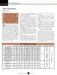
Rule #1<br />
The geometry <strong>of</strong> the joint should have mating surfaces that allow all structural loads to be<br />
transferred in bearing <strong>of</strong> one member against the other. Pegs are best used to hold a joint<br />
together rather than to resist load. Let the geometry <strong>of</strong> the joint do the work, not the pegs.<br />
The truss heel joint shown in Figure 1 illustrates Rule #1.<br />
The compression force in the top chord is transferred to<br />
the bottom chord in bearing on the notch, counteracting<br />
the tension in the bottom chord. The pegs are not resisting<br />
load but have been draw bored to keep the joint tight as<br />
the timbers shrink. The net tension area <strong>of</strong> the bottom<br />
chord has only been reduced slightly (see Rule #2). The<br />
geometry <strong>of</strong> the notch will tend to cause the top chord to<br />
split when the timbers dry and shrink (see Rule #3).<br />
Figure 1 - Truss Heel Joint<br />
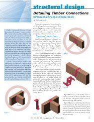
Rule #2<br />
The wood removed to create the joint should not unduly weaken either member. The timber<br />
section <strong>of</strong> both members connected at a joint must be reduced in some fashion to create the joint.<br />
The challenge is to strategically remove wood only from the portion <strong>of</strong> each member that is not<br />
highly stressed. For instance, if a joint occurs at a point <strong>of</strong> maximum moment in a beam, remove<br />
wood near the neutral axis rather than from the extreme<br />
fibers.<br />
The failed butt-cog joint shown in Figure 2 violates<br />
Rule #2. The joists have been deeply notched at the<br />
point <strong>of</strong> maximum shear resulting in a shear failure and<br />
the supporting beam has been notched at the extreme<br />
fibers in bending.<br />
Figure 2 - Failed Butt-Cog Joint<br />
A tusk tenon joint would have been a much better<br />
choice for this situation.<br />
TFEC 2 Tech <strong>Bulletin</strong> No. <strong>2011</strong>‐<strong>03</strong>
Rule #3<br />
The geometry <strong>of</strong> the joint should not be altered by shrinkage <strong>of</strong> the wood and bearing surfaces<br />
should remain in tight contact. This is the rule that is most <strong>of</strong>ten forgotten.<br />
The knee brace joint shown in Figure 3 was tight prior to the<br />
timbers drying and shrinking. The joint is open and the bearing<br />
surfaces are no longer in contact. The mortise should have been<br />
cut deeper than the length <strong>of</strong> the tenon in anticipation <strong>of</strong> the<br />
mortised timber shrinking. The pegs could have been draw bored<br />
to prestress the joint and keep it tight.<br />
Figure 3 - Knee Brace Joint<br />
Rule #4<br />
Anticipate all potential modes <strong>of</strong> failure and provide sufficient strength to resist each potential<br />
failure mode. This is a rule that naturally applies to any structure not just timber joinery.<br />
For example, potential failure modes to consider for the heel joint shown in Figure 1 include:<br />
1. horizontal shear <strong>of</strong> the relish on the bottom chord<br />
2. crushing at the bearing surfaces<br />
3. tension fracture <strong>of</strong> the bottom chord at the notch.<br />
The challenge here is that you must think <strong>of</strong> everything. Failure to anticipate a potential failure<br />
mode can have dire consequences.<br />
Conclusion<br />
The engineering <strong>of</strong> timber joinery is not a cookbook process <strong>of</strong> following overly prescriptive<br />
codes and standards. It requires considerably more ingenuity, creative energy and experience<br />
than the design <strong>of</strong> a typical steel connection. But if you faithfully follow the fundamental rules<br />
described in this technical bulletin, you too can master the art <strong>of</strong> joinery design.<br />
TFEC 3 Tech <strong>Bulletin</strong> No. <strong>2011</strong>‐<strong>03</strong>