Definition and implementation of a global EV ... - Park & Charge
Definition and implementation of a global EV ... - Park & Charge
Definition and implementation of a global EV ... - Park & Charge

Create successful ePaper yourself
Turn your PDF publications into a flip-book with our unique Google optimized e-Paper software.
final report<br />
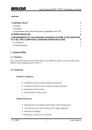
PI+<br />
1 kΩ<br />
R PI U PI<br />
U 0<br />
PI-<br />
Figure 8: Power indicator schematics<br />
To ensure a minimum measuring current, the maximum mains current is coded at 80% <strong>and</strong><br />
above <strong>of</strong> the supply voltage:<br />
I<br />
mainsAC<br />
U<br />
= 20<br />
U<br />
PI<br />
0<br />
, Imax = 16 A, U 0 = open circuit voltage<br />
Special functions <strong>of</strong> the Power Indicator<br />
In some cases it may be required to enable an AC current exceeding the 16A limit. This feature<br />
could be achieved by adding an additional component to the external resistor <strong>and</strong> to process<br />
the impedance:<br />
The internal voltage source becomes a symmetrical bipolar 1kHz square wave generator as it<br />
is used for the Control Pilot. Both the positive <strong>and</strong> the negative voltage at the PI+ is sensed.<br />
The corresponding mains current is to be calculated as follows:<br />
I<br />
mainsAC<br />
U<br />
positive<br />
− U<br />
= 20 ⋅<br />
2 U<br />
0<br />
negative<br />
[A],<br />
, U 0 = open circuit voltage<br />
With a simple resistor, the formula reproduces the same result as the previosly described solution.<br />
By adding a diode, the characteristic will change. There are two possibilities:<br />
17/01/2008 23 Infrastructure for electrical vehicles