Definition and implementation of a global EV ... - Park & Charge
Definition and implementation of a global EV ... - Park & Charge
Definition and implementation of a global EV ... - Park & Charge

You also want an ePaper? Increase the reach of your titles
YUMPU automatically turns print PDFs into web optimized ePapers that Google loves.
final report<br />
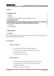
State chart <strong>of</strong> the OMNICHARGE charging station (compatible to SAE1772)<br />
state load condition Reaction <strong>of</strong> the station control pilot signal<br />
O nothing plugged in st<strong>and</strong> by -12V static<br />
trans<br />
0<br />
plugging in<br />
mechanical switch produces<br />
master reset<br />
-12V static<br />
I<br />
any load<br />
An IEC 309-2 connector<br />
was plugged in; detection<br />
by a microswitch<br />
No energization, Reset<br />
<strong>of</strong> the control unit<br />
-12V static<br />
trans<br />
1<br />
unidi<br />
rect<br />
any load<br />
Start signal detected<br />
1. no impedance at the<br />
control pilot<br />
2. all other defined impedances<br />
a wrong impedance<br />
The impedance <strong>of</strong> the<br />
control pilot circuit is<br />
measured.<br />
transition to state A1<br />
(mode 1 with the 16A<br />
path energized)<br />
will cause immediate<br />
transition to the corresponding<br />
state<br />
leads to state X<br />
1kHz, duty cycle depends<br />
on ampacity<br />
positive 12V, pulse<br />
A1<br />
open no Control Pilot communication,<br />
open end<br />
Line current limited to<br />
16A. Mode 1 charging<br />
1kHz, duty cycle depends<br />
on ampacity<br />
still waiting for response<br />
positive 12V, pulse<br />
B<br />
2.7kΩ<br />
+diode<br />
A mode 3 compatible<br />
vehicle has been connected<br />
but is not ready for<br />
energy delivery.<br />
The vehicle is detected<br />
<strong>and</strong> the charging station<br />
waits for transition to C.<br />
1kHz, PWM, 1kΩ internal<br />
resistance<br />
positive 9V, pulse<br />
trans<br />
2<br />
vehicle changes impedance<br />
from 2.7kΩ to<br />
880Ω (240Ω)<br />
Releasing <strong>of</strong> the 32A<br />
path<br />
transition from positive<br />
9V pulse to positive 6V<br />
(3V) pulse<br />
C<br />
880Ω<br />
+diode<br />
A mode 3 compatible<br />
vehicle is connected <strong>and</strong><br />
ready for energy delivery.<br />
The direct transition<br />
from A to C without the<br />
intermediate step B is<br />
also allowed.<br />
Mains will be delivered<br />
to the socket outlet protected<br />
by a 32A line fuse<br />
The continous current is<br />
equal to the ratet value<br />
1kHz, PWM, 1kΩ internal<br />
resistance<br />
positive 6V, pulse<br />
negative -12V, any state<br />
17/01/2008 20 Infrastructure for electrical vehicles