CONNECTIONS
CONNECTIONS
CONNECTIONS

Create successful ePaper yourself
Turn your PDF publications into a flip-book with our unique Google optimized e-Paper software.
Bolted Splices in Compression – Splice Plate Member Checks<br />
Author: Kevin Cowie, Alistair Fussell<br />
Affiliation: Steel Construction New Zealand Inc.<br />
Date: 24 th February 2012<br />
Ref:<br />
CON3101<br />
<strong>CONNECTIONS</strong><br />
Key Words<br />
Splices, Bolted Splice, Compression, Bolted Beam Splice, Bolted Compression Splice<br />
Introduction<br />
The Steel Construction New Zealand publication Steel Connect (SCNZ 14.1 and SCNZ 14.2) provides structural<br />
engineers with a rapid and cost-effective way to specify the majority of structural steelwork connections, in<br />
accordance with accepted fabrication industry norms. Specification of these connections also facilitates the<br />
development of reliable cost estimates by designers, fabricators, consulting quantity surveyors and constructors.<br />
Steel Connect contains bolted beam splice (BBS) and bolted welded beam splice (BWBS) connections. An<br />
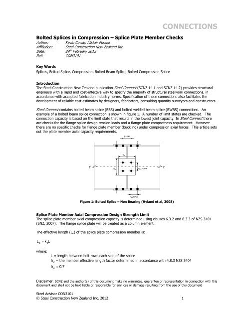
example of a bolted beam splice connection is shown in figure 1. A number of limit states are checked. The<br />
connection capacity is based on the limit state that results in the lowest joint capacity. In Steel Connec there<br />
are checks for the flange splice design tension loads and a flange plate compactness requirement. However<br />
there are no specific checks for flange plate member (buckling) under compression axial forces. This article sets<br />
out the plate member axial capacity requirements.<br />
Figure 1: Bolted Splice – Non Bearing (Hyland et al, 2008)<br />
Splice Plate Member Axial Compression Design Strength Limit<br />
The splice plate member axial compression capacity is determined using clauses 6.3.2 and 6.3.3 of NZS 3404<br />
(SNZ, 2007). The flange splice plate will be treated as a column element.<br />
The effective length (L e ) of the splice plate compression member is:<br />
L<br />
e<br />
k L<br />
e<br />
where:<br />
L = length between bolt rows each side of the splice<br />
k = the member effective length factor determined in accordance with 4.8.3 NZS 3404<br />
e<br />
ke<br />
0.7<br />
Disclaimer: SCNZ and the author(s) of this document make no warrantee, guarantee or representation in connection with this<br />
document and shall not be held liable or responsible for any loss or damage resulting from the use of this document<br />
Steel Advisor CON3101<br />
© Steel Construction New Zealand Inc. 2012 1
The splice plate member axial compression capacity is:<br />
Nic c<br />
N<br />
is<br />
where:<br />
N<br />
is<br />
n<br />
= the design section capacity of the splice plate<br />
L<br />
f<br />
e<br />
yi<br />
kf<br />
r 250<br />
r = radius of gyration<br />
k f = the form factor, taken as 1.0<br />
f yi =plate yield stress (MPa)<br />
Values of the member slenderness reduction factor (<br />
c<br />
) may be obtained directly from table 6.3.3(2) NZS 3404<br />
using the value of the modified member slenderness (<br />
n ) and the appropriate member constant ( b<br />
) given in<br />
table 6.3.3(1) NZS 3404. For splice plates<br />
b<br />
= 0 should be used.<br />
Alternatively,<br />
c<br />
may be calculated as follows.<br />
c<br />
1 1<br />
90<br />
2<br />
90<br />
2<br />
1<br />
2<br />
2 90<br />
n a b<br />
0.00326 13.5 0<br />
a 2<br />
n<br />
2100 13.5<br />
n<br />
15.3 2050<br />
n<br />
Example of Determining Flange Splice Member Axial Compression Design Strength Limit<br />
An 8mm thick flange plate is selected for a bolted splice. The distance between bolt rows is 90mm. The yield<br />
stress (f yi ) is 250 MPa. What is the flange compression splice plate member axial compression capacity<br />
expressed as a percentage of plate section capacity?<br />
Determine modified member slenderness (<br />
n )<br />
n<br />
L<br />
f<br />
e<br />
y<br />
kf<br />
r 250<br />
where:<br />
L k L 0.7 x 90 63mm<br />
e<br />
e<br />
r 0.289t<br />
if<br />
0.289 x 8 2.312<br />
kf<br />
1.0<br />
fy<br />
250MPa<br />
n<br />
63 250<br />
1 27.2<br />
2.312 250<br />
Steel Advisor CON3101<br />
© Steel Construction New Zealand Inc. 2012 2
Determine member slenderness reduction factor (<br />
c )<br />
Using table 6.3.3(2) NZS 3404 for<br />
b<br />
0 :<br />
c<br />
0.95<br />
splice plate member axial compression capacity is 95% of splice plate section capacity<br />
References<br />
Hyland C., Cowie K., Clifton C., Structural Steelwork Connections Guide: Design Procedures, SCNZ 14.1 2007,<br />
Steel Construction New Zealand (Inc), Manukau City, 2008<br />
Hyland C., Cowie K., Bird G., Structural Steelwork Connections Guide: Connection Tables, SCNZ 14.2 2007, Steel<br />
Construction New Zealand (Inc), Manukau City, 2008<br />
SNZ, Steel Structures Standard (Incorporating Amendments 1 and 2), NZS 3404:1997, Standards New Zealand,<br />
Wellington, 2007<br />
Steel Advisor CON3101<br />
© Steel Construction New Zealand Inc. 2012 3