footfall induced vibration in longspan composite steel beams used in ...
footfall induced vibration in longspan composite steel beams used in ...
footfall induced vibration in longspan composite steel beams used in ...

Create successful ePaper yourself
Turn your PDF publications into a flip-book with our unique Google optimized e-Paper software.
Steel Innovations Conference 2013<br />
Christchurch, New Zealand<br />
21-22 February 2013<br />
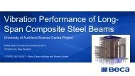
FOOTFALL INDUCED VIBRATION IN LONGSPAN COMPOSITE STEEL BEAMS USED IN TWO<br />
PROJECTS AT THE UNIVERSITY OF AUCKLAND<br />
V.N.Patel 1 and R.J.Built 2<br />
ABSTRACT<br />
Floor <strong>vibration</strong> due to human activity has become <strong>in</strong>creas<strong>in</strong>gly recognised by structural eng<strong>in</strong>eers,<br />
architects, and build<strong>in</strong>g owners as an <strong>in</strong>herent issue <strong>in</strong> long-span <strong>steel</strong> framed floor systems. In the<br />
past, attention was primarily foc<strong>used</strong> on strength and deflection serviceability limits. However, as<br />
designers seek to push the limits on structural spans, grid spac<strong>in</strong>gs and adopt light-weight, low<br />
damp<strong>in</strong>g structural <strong>steel</strong>work floor systems, more detailed consideration is required of the design<br />
tools and processes available to analyse and predict the <strong>vibration</strong> performance of floor systems.<br />
Selection from published criteria of an “acceptable” <strong>vibration</strong> limit is sometimes possible depend<strong>in</strong>g<br />
upon the <strong>in</strong>tended use of the space and the availability of manufacturers’ data for any <strong>vibration</strong><br />
sensitive equipment. Build<strong>in</strong>g Owners and User Groups often have little understand<strong>in</strong>g or<br />
quantitative “feel” for what performance the proposed “acceptable <strong>vibration</strong> limit” actually represents.<br />
The theoretical predication of <strong>vibration</strong> performance aga<strong>in</strong>st actual measured performance can<br />
sometimes vary significantly. This can lead to dispute post-construction as to whether the floor has<br />
an “acceptable” level of <strong>vibration</strong>. Post construction remediation of a space that is deemed to be “too<br />
lively” is often difficult, therefore, it is important that the <strong>vibration</strong> design criteria proposed are<br />
discussed and agreed and the limits of theoretical predications of <strong>vibration</strong> performance are clearly<br />
understood by all parties at the outset.<br />
Beca Carter Holl<strong>in</strong>gs and Ferner Ltd (Beca) are currently <strong>in</strong> the process of design<strong>in</strong>g two projects at<br />
the University of Auckland, utilis<strong>in</strong>g long-span partial-<strong>composite</strong> cellular <strong>steel</strong> <strong>beams</strong>. Both build<strong>in</strong>gs<br />
will utilise exist<strong>in</strong>g structural frame layouts and foundations. As the new structure is to be built on the<br />
exist<strong>in</strong>g foundations, there is a necessity to keep it as lightweight as possible. The question of<br />
<strong>vibration</strong> sensitivity has been raised as a potential issue as both build<strong>in</strong>gs conta<strong>in</strong> research<br />
laboratories. An <strong>in</strong>-depth <strong>in</strong>vestigation has been conducted <strong>in</strong>to the factors affect<strong>in</strong>g <strong>vibration</strong><br />
performance <strong>in</strong> order to give the Client and User Groups confidence that <strong>footfall</strong> <strong><strong>in</strong>duced</strong> <strong>vibration</strong><br />
will not be an issue with the proposed floor structure.<br />
1. Introduction<br />
Client requirements, coupled with architectural and cost constra<strong>in</strong>ts, have demanded new build<strong>in</strong>gs to<br />
provide large un<strong>in</strong>terrupted floor spaces, which are fast to construct with a high degree of adaptability for<br />
build<strong>in</strong>g services. In response to these issues, Eng<strong>in</strong>eers have pushed the limits on column and beam grid<br />
spac<strong>in</strong>gs. Where previously strength and serviceability deflections governed design, it is <strong>in</strong>creas<strong>in</strong>gly the<br />
dynamic performance of floors which require <strong>in</strong>creased consideration. The use of high strength light-weight<br />
cellular <strong>steel</strong> <strong>beams</strong> and <strong>composite</strong> metal-deck floor systems has reduced construction costs through lighter<br />
loads imposed on foundations and reduced craneage requirements. A range of software, <strong>in</strong>clud<strong>in</strong>g f<strong>in</strong>ite<br />
element (FE) tools, are now available to design <strong>composite</strong> long-span floor systems provid<strong>in</strong>g consideration of<br />
both strength and <strong>vibration</strong> issues.<br />
Beca are currently design<strong>in</strong>g two projects at the University of Auckland (UoA) which comprise long-span<br />
partial-<strong>composite</strong> cellular <strong>steel</strong> <strong>beams</strong> and metal-deck floors. The two build<strong>in</strong>gs are to be <strong>used</strong> for<br />
1 Senior Structural Eng<strong>in</strong>eer, Beca Carter Holl<strong>in</strong>gs & Ferner Ltd, Auckland, New Zealand. Email: vijay.patel@beca.com<br />
2 Technical Director, Beca Carter Holl<strong>in</strong>gs & Ferner Ltd, Auckland, New Zealand. Email: richard.built@beca.com
postgraduate research and teach<strong>in</strong>g spaces, as well as office and laboratory areas. Due to the nature of the<br />
<strong>in</strong>tended use, there is a need to m<strong>in</strong>imise <strong>footfall</strong> <strong><strong>in</strong>duced</strong> floor <strong>vibration</strong> effects on occupants and laboratory<br />
equipment.<br />
This paper outl<strong>in</strong>es: the fundamental pr<strong>in</strong>ciples of <strong>vibration</strong> and factors to be considered dur<strong>in</strong>g design,<br />
provides an outl<strong>in</strong>e of the two UoA projects, reviews the analysis and acceptance criteria adopted for the<br />
projects and summarises the on-site test<strong>in</strong>g and validation of the analysis tools <strong>used</strong>.<br />
2. Fundamental Pr<strong>in</strong>ciples of Vibration<br />
To better understand the effect of <strong>footfall</strong> <strong><strong>in</strong>duced</strong> <strong>vibration</strong> on <strong>composite</strong> floor systems, it is necessary to<br />
understand the pr<strong>in</strong>ciples of <strong>vibration</strong>.<br />
2.1 Frequency<br />
The natural frequency of a system, given <strong>in</strong> hertz, Hz (cycles per second), is a measure of the rate at which<br />
the system vibrates 1 . When a cyclic force (e.g. walk<strong>in</strong>g) is applied to a structure, it will beg<strong>in</strong> to vibrate. If the<br />
cyclic force is applied cont<strong>in</strong>uously, the motion of the structure will reach a steady-state (constant amplitude<br />
and frequency).<br />
For floors with a frequency of less than 8Hz, resonance can occur from one of the first four harmonic<br />
components of walk<strong>in</strong>g activity co<strong>in</strong>cid<strong>in</strong>g with the natural frequency of the floor. This is known as resonant<br />
excitation. Conversely, for floors with a sufficiently ‘high frequency’ (such that the first four harmonic<br />
components of the walk<strong>in</strong>g activity do not cause resonance), the response is dom<strong>in</strong>ated by a tra<strong>in</strong> of<br />
impulses correspond<strong>in</strong>g to the heel impacts; which is known as impulsive excitation.<br />
2.2 Modal mass<br />
A mode of <strong>vibration</strong> is characterised by a modal (natural) frequency and a mode shape. Each mode is<br />
<strong>in</strong>dependent of the other modes. All modes have different frequencies and different mode shapes. The<br />
modal mass of a system is a measure of how much mass is <strong>in</strong>volved <strong>in</strong> the particular mode shape. A large<br />
modal mass will require a lot of energy to excite the mode. Systems with larger modal masses will therefore<br />
be less affected by <strong>footfall</strong> <strong><strong>in</strong>duced</strong> <strong>vibration</strong>.<br />
2.3 Excitation<br />
The forc<strong>in</strong>g function from a walk<strong>in</strong>g activity is assumed to be perfectly s<strong>in</strong>usoidal. The excitation imposed to<br />
a floor is affected by the pace frequency, the length of walk<strong>in</strong>g path, and the location of the walk<strong>in</strong>g activity<br />
(excitation) relative to the receiver.<br />
The pace frequency, <strong>used</strong> for design falls <strong>in</strong>to the range 1 :<br />
The excitation po<strong>in</strong>t and response po<strong>in</strong>t should be chosen to produce the maximum response of the floor. In<br />
most cases, the maximum response will be when excitation and receiver are at the po<strong>in</strong>t of maximum modal<br />
displacement.<br />
2.4 Response<br />
Calculation of floor <strong>vibration</strong> response considers the mass,<br />
stiffness and damp<strong>in</strong>g properties of the structure, and by apply<strong>in</strong>g<br />
an appropriate excitation function 2 . For low frequency floors, both<br />
the steady state response and transient response need to be<br />
checked, as the higher frequencies of the floor may result <strong>in</strong> the<br />
transient response be<strong>in</strong>g greater than the steady state 3 . For high<br />
frequency floors only the transient response needs to be checked.<br />
The Response factor of a floor is the ratio between the calculated<br />
weighted RMS (root-mean-square) acceleration, and the base<br />
value given <strong>in</strong> BS6472 4 . This standard covers many <strong>vibration</strong><br />
environments <strong>in</strong> build<strong>in</strong>gs. Limits of satisfactory <strong>vibration</strong><br />
magnitude are expressed <strong>in</strong> relation to a frequency-weighted<br />
‘base curve’ and a series of multiply<strong>in</strong>g response factors. A<br />
Response factor of 1 (R = 1) is the level of <strong>vibration</strong> that can just<br />
be perceived by humans. R=2 is twice as much as can just be felt<br />
(etc).<br />
Figure 1. Build<strong>in</strong>g Vibration Curves<br />
For z-axis Vibrations 4
2.5 Damp<strong>in</strong>g<br />
Damp<strong>in</strong>g describes the amount of energy dissipation that occurs when a structure vibrates. With higher<br />
levels of damp<strong>in</strong>g, more energy is dissipated as sound and heat, which <strong>in</strong> turn, leads to lower levels of<br />
structural <strong>vibration</strong> 5 . The fact that no system will oscillate <strong>in</strong>def<strong>in</strong>itely without an applied load, shows that all<br />
structures conta<strong>in</strong> some level of <strong>in</strong>herent damp<strong>in</strong>g. When calculat<strong>in</strong>g <strong>vibration</strong> responses, it is important to<br />
use a realistic estimate of structural damp<strong>in</strong>g. Experience with floors of similar construction will provide a<br />
more accurate estimate of the likely amount of damp<strong>in</strong>g that may be achieved.<br />
3. University of Auckland Projects<br />
3.1 University of Auckland – Science Centre Build<strong>in</strong>g B302<br />
The proposed new 13 storey Science Centre Tower is located on the<br />
corner of Symonds Street and Wellesley Street East on the University<br />
of Auckland Central City Campus. The new structure is located on the<br />
site of an exist<strong>in</strong>g 3 storey build<strong>in</strong>g and will utilise the exist<strong>in</strong>g build<strong>in</strong>g<br />
grid set-out and foundations. As the new structure is to be built on the<br />
exist<strong>in</strong>g foundations, there is a necessity to keep it as light as possible.<br />
The new structure is a <strong>steel</strong> braced frame build<strong>in</strong>g utilis<strong>in</strong>g Buckl<strong>in</strong>g<br />
Restra<strong>in</strong>ed Braces (BRB’s). The gravity structure consists of <strong>steel</strong><br />
welded I-section columns, support<strong>in</strong>g tapered <strong>steel</strong> primary <strong>beams</strong><br />
spann<strong>in</strong>g 6.4m, partial-<strong>composite</strong> long-span cellular secondary <strong>beams</strong><br />
at 3.2m centres spann<strong>in</strong>g 13.4m and 14.8m, with a 140mm-thick<br />
<strong>composite</strong> re<strong>in</strong>forced-concrete metal deck<strong>in</strong>g. The cellular <strong>beams</strong> are<br />
800mm deep with 500mm diameter penetrations at regular centres, to<br />
allow for services reticulation. These <strong>beams</strong> have been designed as<br />
partial-<strong>composite</strong> members as a layer of visco-elastic material has<br />
been <strong>used</strong> over half the beam-span to provide additional damp<strong>in</strong>g to the<br />
floor system.<br />
Figure 2. UoA Science Centre<br />
Build<strong>in</strong>g B302<br />
3.2 University of Auckland – Faculty of Eng<strong>in</strong>eer<strong>in</strong>g Extension – B403/B404<br />
The Faculty of Eng<strong>in</strong>eer<strong>in</strong>g is located on the corner of Grafton Road and Symonds Street on the University of<br />
Auckland Central City Campus. The exist<strong>in</strong>g School of Eng<strong>in</strong>eer<strong>in</strong>g Build<strong>in</strong>gs B403 and B404 are four level<br />
re<strong>in</strong>forced concrete structures. The proposed extension comprises an additional six new lightweight stories<br />
be built above the exist<strong>in</strong>g.<br />
Figure 3. UoA Eng<strong>in</strong>eer<strong>in</strong>g School Build<strong>in</strong>g<br />
The proposed structure is an exosketetal <strong>steel</strong> frame with<br />
BRB brac<strong>in</strong>g, erected on the outside of the exist<strong>in</strong>g<br />
build<strong>in</strong>g envelope support<strong>in</strong>g the vertical and lateral loads<br />
of the new floors above. The gravity structure consists of<br />
<strong>steel</strong> primary <strong>beams</strong> spann<strong>in</strong>g 6.2m, with partial<strong>composite</strong><br />
long-span cellular secondary <strong>beams</strong> at 3.1m<br />
centres spann<strong>in</strong>g 12.2m and 13.4m, with a 140-thick<br />
<strong>composite</strong> re<strong>in</strong>forced-concrete metal deck<strong>in</strong>g. Like the<br />
proposed Science Centre Tower, the cellular <strong>beams</strong> have<br />
been designed as partial-<strong>composite</strong> members, as a layer<br />
of visco-elastic material has been <strong>used</strong> over half the span<br />
to provide additional damp<strong>in</strong>g to the floor system.<br />
4. Design Assumptions / Considerations for Science Centre Build<strong>in</strong>g B302<br />
Vibration issues aris<strong>in</strong>g from us<strong>in</strong>g long-span <strong>composite</strong> <strong>steel</strong> <strong>beams</strong> can often be m<strong>in</strong>imised and mitigated,<br />
if the result<strong>in</strong>g issues are identified early <strong>in</strong> the design process. Early identification of factors contribut<strong>in</strong>g to<br />
a lively floor enables the Design Team to consider mitigation measures that can be easily <strong>in</strong>corporated <strong>in</strong>to<br />
the design development.<br />
The follow<strong>in</strong>g items were encountered and considered dur<strong>in</strong>g the design of the University of Auckland<br />
Science Centre project:
4.1 Floor Span and Structural Set-Out<br />
The frequency of a floor system is directly related to its stiffness. The stiffness of the structure is <strong>in</strong>versely<br />
related to its span. Therefore, as the span of the floor or support<strong>in</strong>g <strong>beams</strong> <strong>in</strong>crease, the stiffness decreases,<br />
creat<strong>in</strong>g a livelier floor. By provid<strong>in</strong>g a floor system and support<strong>in</strong>g structure that is not too slender for the<br />
required spans, <strong>vibration</strong> characteristics of the system can be controlled.<br />
The University has a requirement to provide large clear-span spaces free of columns, to maximise efficiency<br />
of <strong>in</strong>terior room layouts, and provide flexibility for future space plann<strong>in</strong>g layout changes to meet chang<strong>in</strong>g<br />
User Group needs. The exist<strong>in</strong>g build<strong>in</strong>g structural layout with columns at a grid spac<strong>in</strong>g of 6.2m by 13.4m<br />
and 14.8m, provides architecturally efficient space plann<strong>in</strong>g and enables re-use of exist<strong>in</strong>g build<strong>in</strong>g<br />
foundations; but led to an <strong>in</strong>herently flexible structural system us<strong>in</strong>g <strong>steel</strong> structure.<br />
Alternative grid options with additional columns, to reduce beam spans and stiffen the floor system, were<br />
<strong>in</strong>vestigated at an early stage. The alternative grid layouts resulted <strong>in</strong> a cheaper structure solution, with<br />
better <strong>vibration</strong> performance, however, the University decided that the reduction <strong>in</strong> space plann<strong>in</strong>g flexibility<br />
associated with these alternative layouts out-weighted the reduced cost and improved <strong>vibration</strong> performance.<br />
Floor penetrations and atrium voids create areas of structural discont<strong>in</strong>uity, but are aesthetically pleas<strong>in</strong>g.<br />
There are three ma<strong>in</strong> atrium void configurations up the height of the build<strong>in</strong>g. The <strong>vibration</strong> performance of<br />
the floor adjacent to the voids is found to be more sensitive than areas away from the voids. Special<br />
consideration of the <strong>vibration</strong> response of cantilevered balcony slabs and backspan <strong>beams</strong> at the atriums<br />
was required.<br />
4.2 Floor Mass (Modal Mass Participation)<br />
The amount of mass associated with a floor plate affects its <strong>vibration</strong> response. The mass <strong>used</strong> <strong>in</strong> the<br />
<strong>vibration</strong> analysis needs to accurately represent the mass actually present. For <strong>vibration</strong> assessment, the unfactored<br />
self-weight of the structure, plus super-imposed dead loads of items actually present (such as<br />
ceil<strong>in</strong>gs, floor cover<strong>in</strong>g, services etc.), plus a nom<strong>in</strong>al 10% allowance for imposed live loads is<br />
recommended.<br />
Add<strong>in</strong>g mass to the floor system can reduce <strong>vibration</strong> response. For the Science Centre, the structure needs<br />
to be kept as light as possible so as not to overload the reta<strong>in</strong>ed exist<strong>in</strong>g foundations, from the additional 10<br />
floor levels. A 140-thick ComFlor60 profile metal deck<strong>in</strong>g was adopted given its long-span capability, and low<br />
mass properties.<br />
4.3 Damp<strong>in</strong>g<br />
The amount of damp<strong>in</strong>g assessed to be provided <strong>in</strong> the end state can considerably affect the f<strong>in</strong>al results of<br />
the <strong>vibration</strong> analysis. Guidel<strong>in</strong>es are provided for the amount of damp<strong>in</strong>g that a given structural system and<br />
fit-out may provide; see Table 1, extracted from P354 1 , below:<br />
Table 1. Critical Damp<strong>in</strong>g Ratios for Various Floor Types 1<br />
However, the actual amount of damp<strong>in</strong>g present may vary dur<strong>in</strong>g the life of the build<strong>in</strong>g. The additional<br />
damp<strong>in</strong>g provided by fit-out (such as services, partitions, suspended ceil<strong>in</strong>gs, furniture and fixtures) may be<br />
reduced by future fit-out changes.<br />
On the University projects, the level of damp<strong>in</strong>g provided by the base structure and limited architectural<br />
f<strong>in</strong>ishes was assumed to be 2%. To provide a long-term dependable level of damp<strong>in</strong>g, a viscoelastic layer<br />
(Resotec) was provided between the cellular <strong>beams</strong> top flange and concrete slab. The Resotec provides an<br />
additional 2% damp<strong>in</strong>g, regardless of the level of <strong>in</strong>ternal fit-out. The ‘Base Case’ for the <strong>vibration</strong> analysis of<br />
the structure therefore assumed a total of 4% damp<strong>in</strong>g.
4.4 Support/Restra<strong>in</strong>t Conditions<br />
For the purposes of floor <strong>vibration</strong> response, the <strong>beams</strong> can be assumed to be fixed-end restra<strong>in</strong>ed at<br />
<strong>in</strong>terior supports, even if a nom<strong>in</strong>al structural p<strong>in</strong> connection is provided, as the stra<strong>in</strong>s <strong>in</strong> the floor system<br />
<strong><strong>in</strong>duced</strong> dur<strong>in</strong>g <strong>vibration</strong> are not large enough to overcome the frictional forces <strong>in</strong> the jo<strong>in</strong>ts.<br />
Vertical restra<strong>in</strong>t is also applied to the floor by the façade connections at each floor slab around the perimeter<br />
of the build<strong>in</strong>g and balustrad<strong>in</strong>g around the perimeter of the atriums. Sensitivity of this assumption was<br />
checked by modell<strong>in</strong>g the façade elements and the balustrades <strong>in</strong> a F<strong>in</strong>ite Element (FE) model. P<strong>in</strong>ned<br />
vertical supports were modelled for these elements.<br />
4.5 Effect of Partitions<br />
Internal partitions provide a mechanism to <strong>in</strong>terrupt the <strong>vibration</strong> response of a floor. The partitions can<br />
behave <strong>in</strong> one of two ways, depend<strong>in</strong>g on their detail<strong>in</strong>g and connectivity. An <strong>in</strong>ternal partition wall that spans<br />
from a given floor to the floor above, with direct connection, will connect the floor slabs together and act to<br />
reduce <strong>vibration</strong> by mobilis<strong>in</strong>g the mass of both floors. An <strong>in</strong>ternal partition that does not connect directly to<br />
the floor above, but rather stops at the suspended ceil<strong>in</strong>g will <strong>in</strong>crease the damp<strong>in</strong>g to the floor.<br />
To demonstrate what the system can achieve (as a m<strong>in</strong>imum), a bare floor has been analysed, and this is<br />
considered as the ‘Base Case’. This would be applicable, should open-plan layouts of the floor be required.<br />
A case modell<strong>in</strong>g the variable effect of partitions proposed was considered and it was found that the partition<br />
walls significantly improved the floor <strong>vibration</strong> response.<br />
4.6 Excitation<br />
The response of a floor system differs across its width. Nodal l<strong>in</strong>es form at stiff areas such as column and<br />
beam l<strong>in</strong>es, and these areas will be less responsive than areas <strong>in</strong> the middle of the slab and beam. The<br />
excitation po<strong>in</strong>t and response po<strong>in</strong>t will generally produce the maximum effect when they are <strong>in</strong> the same<br />
location. In reality, these two po<strong>in</strong>ts are not always go<strong>in</strong>g to co<strong>in</strong>cide.<br />
By consider<strong>in</strong>g the location, length and cont<strong>in</strong>uity of corridors and walk<strong>in</strong>g paths, the effect of the response<br />
generated can be controlled. The longer the walk<strong>in</strong>g path, the higher the dose of <strong>vibration</strong> that will be<br />
transmitted to other floor areas. By break<strong>in</strong>g up the walk<strong>in</strong>g paths or corridors <strong>in</strong>to discrete lengths, the<br />
duration of cont<strong>in</strong>uous walk<strong>in</strong>g activity will reduce, and the dose of <strong>vibration</strong> will consequently decrease.<br />
SCI P354 1 recommends that the ‘average’ mass for a human be<strong>in</strong>g, and hence, the assumed mass for the<br />
applied <strong>footfall</strong> source, is 76kg. This document also recommends a walk<strong>in</strong>g frequency of 1.8-2.2Hz to be<br />
<strong>used</strong> dur<strong>in</strong>g design; these excitation masses and frequencies were <strong>used</strong> <strong>in</strong> the analysis of the University of<br />
Auckland projects.<br />
The floors have been <strong>in</strong>dependently checked for <strong>footfall</strong> <strong><strong>in</strong>duced</strong> floor <strong>vibration</strong>, and for <strong>vibration</strong> response<br />
from mechanical plant. Mechanical plant is to be appropriately isolated, either on isolation bear<strong>in</strong>g pads or<br />
positioned <strong>in</strong> areas where it will not cause adverse effect to the build<strong>in</strong>g occupants.<br />
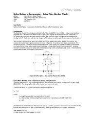
4.7 Composite Beam Action<br />
Structural <strong>steel</strong> <strong>beams</strong> support<strong>in</strong>g metal deck floor slabs have the ability for the <strong>steel</strong> <strong>beams</strong> to be<br />
constructed <strong>composite</strong> with the concrete floor slab through shear stud connection. This <strong>composite</strong> shear stud<br />
connection significantly <strong>in</strong>creases the stiffness of the support beam, improv<strong>in</strong>g the <strong>vibration</strong> characteristics of<br />
the floor system.<br />
Composite design of long-span <strong>steel</strong> <strong>beams</strong> is generally required to provide a cost-effective solution to<br />
withstand ULS loads for strength and SLS loads for deflection. Although, when m<strong>in</strong>imis<strong>in</strong>g the size of the<br />
<strong>steel</strong> beam for strength, this may give rise to susceptibility to dynamic load<strong>in</strong>g, such as <strong>footfall</strong> <strong><strong>in</strong>duced</strong><br />
<strong>vibration</strong>.<br />
Once <strong>vibration</strong> is taken <strong>in</strong>to account, there may be a need to <strong>in</strong>crease the m<strong>in</strong>imum beam size to provide<br />
additional stiffness. Dur<strong>in</strong>g Prelim<strong>in</strong>ary Design of the floor systems, it was found they were relatively lively<br />
us<strong>in</strong>g an 800mm deep <strong>composite</strong> cellular beam with 140mm thick ComFlor60 metal deck<strong>in</strong>g, if a m<strong>in</strong>imum<br />
2% damp<strong>in</strong>g was assumed.<br />
Given that satisfactory <strong>vibration</strong> performance was not able to be obta<strong>in</strong>ed with 2% damp<strong>in</strong>g, it was decided<br />
to provide additional damp<strong>in</strong>g us<strong>in</strong>g a visco-elastic material <strong>in</strong>serted between the slab and <strong>steel</strong> beam. A<br />
proprietary visco-elastic product called Resotec, produced <strong>in</strong> the United K<strong>in</strong>gdom, developed by Arup Group,
and distributed by Richard Lees Steel Deck<strong>in</strong>g, was selected. This product is capable of achiev<strong>in</strong>g an<br />
additional 2% damp<strong>in</strong>g when placed over the outer quarter spans of the <strong>steel</strong> <strong>beams</strong>. Shear studs are<br />
omitted from the Resotec regions and only provided over the middle half of the beam span provid<strong>in</strong>g full<br />
<strong>composite</strong> connection over the maximum moment region.<br />
Figure 4. Partially Composite Beam with Resotec Visco-Elastic Layer<br />
4.8 Acceptance Criteria<br />
Consultation with the Client and User Groups of the build<strong>in</strong>g has been undertaken to ascerta<strong>in</strong> the required<br />
<strong>vibration</strong> characteristics of the various areas with<strong>in</strong> the build<strong>in</strong>g. For example, <strong>vibration</strong> requirements for a<br />
laboratory research space are more str<strong>in</strong>gent than those for an academic office or post-graduate write-up<br />
space. Similarly, <strong>in</strong>creased <strong>vibration</strong> response can be accepted <strong>in</strong> “active” areas such as public foyers and<br />
lobby areas.<br />
To provide a reference datum of the amount of <strong>vibration</strong> currently experienced and deemed acceptable,<br />
various spaces with<strong>in</strong> exist<strong>in</strong>g build<strong>in</strong>gs was subject to <strong>vibration</strong> test<strong>in</strong>g. Test<strong>in</strong>g of exist<strong>in</strong>g spaces <strong>in</strong>cluded<br />
measur<strong>in</strong>g modal properties from various dynamic excitations, and data logg<strong>in</strong>g of background <strong>vibration</strong><br />
levels over a 48 hour period. This provided basel<strong>in</strong>e “acceptance criteria” based on exist<strong>in</strong>g normal usage,<br />
with a reference that was mean<strong>in</strong>gful to the Client and User Groups.<br />
The acceptance criteria f<strong>in</strong>ally adopted, as noted <strong>in</strong> Section 5.2, were based on a comb<strong>in</strong>ation of the desires<br />
of the Client and User Groups, measurement of the <strong>vibration</strong> response of exist<strong>in</strong>g spaces, and guidance from<br />
<strong>in</strong>dustry documentation such as BS6472 4 , SCI P354 1 , ASHRAE 2003 6 and ISO2631 7 and published data for<br />
various items of research equipment.<br />
4.9 Architectural Considerations<br />
Space plann<strong>in</strong>g can affect how much of an issue <strong>vibration</strong> may be. The distribution of corridors, corridor<br />
lengths and relativity of excitation to receptors, will determ<strong>in</strong>e the effect of a given walk<strong>in</strong>g path. If these<br />
walk<strong>in</strong>g paths are conf<strong>in</strong>ed to stiffer areas of floors, such as beam l<strong>in</strong>es and/or columns, then the effect of the<br />
walk<strong>in</strong>g path can be m<strong>in</strong>imised. The location of receptors to mach<strong>in</strong>ery or plant can also determ<strong>in</strong>e the effect<br />
of a cont<strong>in</strong>uous source of <strong>vibration</strong>. If all plant is conf<strong>in</strong>ed to say the roof level plant room or basement, and<br />
typically there is no human occupancy or the floor is a slab on grade (<strong>in</strong> the case of the basement), then the<br />
effect of this plant will be m<strong>in</strong>imised.<br />
Specific users of a build<strong>in</strong>g may have the need to be situated <strong>in</strong> areas of low response, due to the nature of<br />
their work or the equipment they use. If this is the case, rather than try<strong>in</strong>g to employ a solution across the<br />
whole floor plate, or even the entire build<strong>in</strong>g, it may be possible to situate them <strong>in</strong> a location that does not<br />
respond as much as other areas e.g. on a slab on grade, over a nodal zone, or away from sources or<br />
locations of excitation.<br />
4.10 Post Construction Changes<br />
Remedial action once a floor is <strong>in</strong> service is often challeng<strong>in</strong>g and expensive. It may be easier to reconfigure<br />
floors, move people or equipment away from <strong>vibration</strong> sources or walk<strong>in</strong>g paths, or alter the tim<strong>in</strong>g of the<br />
<strong>vibration</strong> activity, rather than look for <strong>in</strong>trusive solutions.<br />
If the floor configuration is not able to be altered, then there may be a need to change the response of the<br />
floor system. This may be achieved by add<strong>in</strong>g mass to the floor, which is not usually very effective and may<br />
affect other structural elements, <strong>in</strong>creas<strong>in</strong>g the stiffness of the floor support members by stiffen<strong>in</strong>g beam<br />
elements, add<strong>in</strong>g additional columns, provid<strong>in</strong>g stiffeners under the floor slab, provid<strong>in</strong>g partition wall<br />
systems to lower deflections, provide damp<strong>in</strong>g mechanisms such as tuned mass dampers or specialist<br />
damp<strong>in</strong>g materials, or isolat<strong>in</strong>g <strong>vibration</strong> sources by us<strong>in</strong>g isolation pads under mechanical plant (etc).
5. Acceptance Criteria for University of Auckland Projects<br />
5.1 Guidel<strong>in</strong>es on Acceptability Limits<br />
Correlation of the physical movement of a floor under excitation to a correspond<strong>in</strong>g acceptance limit is hard<br />
to determ<strong>in</strong>e. The acceptability of movement is based on human perception, and can be subject to an<br />
<strong>in</strong>dividual’s <strong>in</strong>terpretation, unless quantitative values are assigned. As perception and discomfort can vary<br />
between humans, current standards propose criteria that will attract a ‘low probability’ of adverse comment.<br />
Research has been carried out to assess the effect of human response to <strong>vibration</strong>, and is captured <strong>in</strong> a<br />
number of <strong>in</strong>ternational standards. Documents such as BS 6472:1992, BS 6841, ISO 10137, ISO 2631-1<br />
and ISO 2631-2, cover many environments, and look to express the limits of satisfactory <strong>vibration</strong> magnitude<br />
<strong>in</strong> relation to a frequency-weighted ‘base curve’ and series of multiply<strong>in</strong>g factors.<br />
The base curves for <strong>vibration</strong> represent the threshold of human perception, def<strong>in</strong>ed by a ‘base value’, which<br />
is given as a Root Mean Square (RMS) acceleration of 5x10 -3 ms -2 for z-axis <strong>vibration</strong>s and 3.57x10 -3 ms -2 for<br />
x- and y-axis <strong>vibration</strong>s 8 ; see directions of <strong>vibration</strong> and base curves <strong>in</strong> figures 5 and 6 below. The base<br />
value of acceleration that can be perceived depends on the direction of <strong>in</strong>cidence to the human body, where<br />
the z-axis corresponds to the direction of the human sp<strong>in</strong>e. As noted above, the x- or y-axis <strong>vibration</strong> is more<br />
easily perceived (has a lower base value for perception). Each of the base curves are <strong>in</strong>creased by a<br />
multiplication factor (or Response Factor) depend<strong>in</strong>g on the m<strong>in</strong>imum <strong>vibration</strong> perception deemed to be<br />
appropriate for a given environment.<br />
Figure 5. Directions of Vibration<br />
Def<strong>in</strong>ed <strong>in</strong> ISO 2631 7 and BS 6472 4<br />
Figure 6. Base Curves for Perception of Vibration, taken<br />
from BS 6472 4<br />
5.2 Adopted Acceptance Criteria<br />
The follow<strong>in</strong>g tables <strong>in</strong>dicate the proposed acceptance criteria that were established through consultation<br />
with the Client and User Groups, and rationalisation based on test<strong>in</strong>g carried out <strong>in</strong> occupied spaces. This<br />
criterion has been established to attract a ‘low probability’ of adverse comment dur<strong>in</strong>g use of the various<br />
spaces <strong>in</strong> the build<strong>in</strong>g. Vibration sensitive mach<strong>in</strong>es have been positioned on stiffer parts of the floor, and<br />
may have <strong>in</strong>dependent isolators, to prevent adverse effect. Mechanical plant that could cause adverse<br />
excitation will be isolated and/or positioned <strong>in</strong> the basement or plant levels to m<strong>in</strong>imise effects.<br />
Description of Use / Occupancy of Area<br />
BBN Curve [Note 1]<br />
Suggested "Target"<br />
Response factor "R"<br />
Suggested Theoretical<br />
predicted "R" (Max<br />
peak) [Note 2]<br />
Mechanical Plant Space / Plantroom 8 10<br />
Public Circulation Area (no long term seat<strong>in</strong>g) 6 7.5<br />
Atrium Meet<strong>in</strong>g / Break-out Spaces. Seat<strong>in</strong>g with nearby<br />
5 6.5<br />
walk<strong>in</strong>g movements<br />
Academic Office 4 5<br />
PGR Office / Write-up Space 4 5<br />
Computer Laboratory / Teach<strong>in</strong>g Space 4 5<br />
General Post-Grad Research Laboratory Space 4 5<br />
"Sensitive locations" with<strong>in</strong> build<strong>in</strong>g<br />
e.g. Sensitive equipment zones <strong>in</strong> Research Laboratory<br />
Space<br />
2 2.5
Notes:<br />
1. BBN Classification from “The Control of Vibration <strong>in</strong> Build<strong>in</strong>gs” – BBN Laboratories, Cambridge MA, 1988 by C.Gordon.<br />
2. Beca estimate of “target” for Max. Peak values predicted by OASYS GSA F<strong>in</strong>ite Element Program (assumed 25% <strong>in</strong>crease on<br />
ISO2631 criteria).<br />
Table 2. University of Auckland Science Centre Adopted Vibration Criteria<br />
6. Vibration Analysis of B302<br />
6.1 Footfall Induced Vibration Modell<strong>in</strong>g <strong>used</strong> on B302 Science Centre<br />
Dynamic response of the floor structure was highlighted as an issue at the early stages of the project, due to<br />
the grid spac<strong>in</strong>g of columns and lightweight structure proposed. As the design progressed it became<br />
apparent that dynamic response was go<strong>in</strong>g to significantly <strong>in</strong>fluence the design of the gravity floor support<br />
system. A greater degree of certa<strong>in</strong>ty of performance and level of analysis was therefore required.<br />
Prelim<strong>in</strong>ary design of the structure was first analysed us<strong>in</strong>g the proprietary Fabsec and CellBeam software<br />
programs. This was verified us<strong>in</strong>g the Hera NZ Floor Vibration Analysis Program version 2 Microsoft Excel<br />
Spreadsheet and a hand-check us<strong>in</strong>g the guidance of SCI P354 1 . This confirmed that a more <strong>in</strong>-depth<br />
analysis was required, and a F<strong>in</strong>ite Element (FE) model was created us<strong>in</strong>g Oasys GSA 9 Software, to model<br />
the floor plates <strong>in</strong> 3D.<br />
Vibration analysis was completed under the guidance of SCI Publication P354, 2007. Two different methods<br />
of analysis were evaluated, with the first be<strong>in</strong>g a conservative hand-calculation estimate. It was found that<br />
the peak response of the floor system was <strong>in</strong> excess of the prescribed maximum for the given workspace.<br />
The P354 ref<strong>in</strong>ed approach is to assess the floor system us<strong>in</strong>g F<strong>in</strong>ite Element (FE) modell<strong>in</strong>g. FE modell<strong>in</strong>g<br />
takes a cont<strong>in</strong>uous structure and breaks it up <strong>in</strong>to a<br />
number of discrete elements. The relationship<br />
between these elements are then determ<strong>in</strong>ed us<strong>in</strong>g<br />
methods for multi-degree-of-freedom discrete<br />
systems. Oasys GSA software 9 , developed by Arup,<br />
was <strong>used</strong> to model the floor system. Three typical<br />
levels of the Science Centre Tower were assessed;<br />
Levels 2, 5 and 7 (the other floors are similar <strong>in</strong> nature<br />
to these). Floor <strong>vibration</strong> was measured <strong>in</strong> terms of a<br />
Response Factor, R. Response evaluated <strong>in</strong> Oasys<br />
GSA reported values were then evaluated as peak,<br />
average and po<strong>in</strong>t values. The peak value represents<br />
the absolute maximum response factor of the floor<br />
given its chosen parameters. The average response<br />
factor represents a mean peak value across the floor.<br />
The po<strong>in</strong>t value evaluates a chosen po<strong>in</strong>t on the floor<br />
which is the same location for each output, <strong>used</strong> to<br />
compare the response to the variables evaluated.<br />
6.2 Variables <strong>used</strong> dur<strong>in</strong>g modell<strong>in</strong>g and their effect<br />
A ‘Base Case’ was established for each floor, which had an assumed “worst-case” damp<strong>in</strong>g value of 4% for<br />
a bare floor. The 4% comprised a 2% allowance for the floor system itself (re<strong>in</strong>forced concrete, re<strong>in</strong>forced<br />
<strong>steel</strong> deck system, and <strong>steel</strong> <strong>beams</strong>) with no partitions or furniture, and 2% account<strong>in</strong>g for the Resotec viscoelastic<br />
damp<strong>in</strong>g layer provided. As outl<strong>in</strong>ed <strong>in</strong> Section 4.4, façade restra<strong>in</strong>t to the perimeter of the structure<br />
and balustrade restra<strong>in</strong>t to the atrium areas was applied. From this base case, a number of <strong>in</strong>dependent and<br />
concurrent variables were exam<strong>in</strong>ed to determ<strong>in</strong>e their effect on <strong>vibration</strong> performance.<br />
The follow<strong>in</strong>g variables were assessed:<br />
Figure 7. Typical Base case plot for Level 2<br />
6.2.1 Floor Beam Stiffeners<br />
Tertiary 200UB floor stiffeners were placed perpendicular to the castellated <strong>beams</strong> at mid-span, to mobilise<br />
more mass at the location of maximum response. This had a positive effect on reduc<strong>in</strong>g the floor response<br />
by an R factor of about 0.3 to 0.4. This solution was <strong>in</strong>corporated <strong>in</strong>to the design to provide acceptable<br />
response at atrium areas.
6.2.2 Increased Damp<strong>in</strong>g<br />
An <strong>in</strong>creased level of damp<strong>in</strong>g of 5% and 6% was analysed to evaluate the effectiveness of an <strong>in</strong>accuracy <strong>in</strong><br />
the estimate of the actual damp<strong>in</strong>g available. The level of damp<strong>in</strong>g that may be available could <strong>in</strong>crease <strong>in</strong> a<br />
number of ways, <strong>in</strong>clud<strong>in</strong>g, the actual <strong>in</strong>herent damp<strong>in</strong>g from the floor system, from furnish<strong>in</strong>gs, fixtures and<br />
services, or from superior performance from the visco-elastic material (Resotec) to that assumed.<br />
From test results from the AUT-WG build<strong>in</strong>g (which has a floor system similar to the proposed new<br />
structure), it was found that the damp<strong>in</strong>g from a bare floor was 2.2%. This provided validation to the<br />
estimated 2%. From the proposed architectural layouts, furnish<strong>in</strong>gs are <strong>in</strong>dicated <strong>in</strong> all areas, and there is no<br />
current requirement for whole-floor open plan spaces. The presence of fixtures and furnish<strong>in</strong>gs could<br />
potentially <strong>in</strong>crease the damp<strong>in</strong>g available by 1 to 2% from the m<strong>in</strong>imum 4% base case assumption.<br />
6.2.3 Internal Partition Walls<br />
As noted <strong>in</strong> Section 4.5, <strong>in</strong>ternal partitions can have a positive effect by significantly reduc<strong>in</strong>g floor <strong>vibration</strong><br />
response. Sensitivity analysis led us to model the <strong>in</strong>ternal partition walls, by creat<strong>in</strong>g an element with the<br />
same effective stiffness as a 100mm wide timber stud wall with a s<strong>in</strong>gle layer of gib-board either side. This<br />
was deemed appropriate over a blanket <strong>in</strong>crease <strong>in</strong> damp<strong>in</strong>g value applied to the whole floor. An allowance<br />
for doorways was made, by not modell<strong>in</strong>g partitions at these locations. Modell<strong>in</strong>g partition walls reduced the<br />
floor response to <strong>vibration</strong> by a reduction <strong>in</strong> R factor of 2 to 4, depend<strong>in</strong>g on the extent of partition and base<br />
level of damp<strong>in</strong>g assumed. The Client was advised that this improved response might be lost should open<br />
plan office layouts be adopted <strong>in</strong> the future or the full height corridor walls be removed.<br />
6.2.4 Deeper Secondary Beams<br />
Use of a deeper castellated beam was analysed to determ<strong>in</strong>e the cost-effectiveness and change <strong>in</strong> dynamic<br />
response. A 900mm deep member was designed and modelled, <strong>in</strong> lieu of the 800mm deep sections .It was<br />
found that the reduction <strong>in</strong> response was m<strong>in</strong>or with an R value reduction of only 0.1.<br />
6.2.5 Increased Floor Slab Mass<br />
An <strong>in</strong>crease <strong>in</strong> modal mass has been proven to reduce floor <strong>vibration</strong> response. A 140Comflor60 deck was<br />
assumed as the ‘Base Case’ floor system. It was found that by chang<strong>in</strong>g the floor slab system to a 140-flat<br />
deck profile, a 25% <strong>in</strong>crease <strong>in</strong> slab mass can be achieved. The <strong>in</strong>creased modal mass reduced the floor<br />
<strong>vibration</strong> response, with a reduction of R=2.6. However, the cost associated with <strong>in</strong>creased floor mass is not<br />
just the cost of the concrete itself. The additional demand placed on <strong>beams</strong>, columns, foundations and<br />
lateral brac<strong>in</strong>g system meant that this solution was not deemed acceptable.<br />
Figure 8. UoA B302 Base Case, No<br />
Partitions, Resotec, 4% Damp<strong>in</strong>g<br />
Figure 9. UoA B302 Partitions<br />
Modeled, Resotec, 4% Damp<strong>in</strong>g
6.2.6 Other factors<br />
Other factors to be considered <strong>in</strong>clude:<br />
Location of excitation has been assumed to be <strong>in</strong> the worst place for a receiver placed anywhere on the<br />
floor. There are def<strong>in</strong>ed walk<strong>in</strong>g paths, dictated by the corridors and furniture layouts, and this beneficial<br />
effect has not been taken account of <strong>in</strong> the general analysis, but was <strong>used</strong> when consider<strong>in</strong>g the<br />
performance of localised specialist areas.<br />
The nature of <strong>footfall</strong> <strong><strong>in</strong>duced</strong> <strong>vibration</strong> is that the excitation is <strong>in</strong>termittent. In the FE models created,<br />
excitation has been considered as cont<strong>in</strong>uous, and therefore the maximum response experienced by a<br />
receiver would be sporadic, rather than constant. This may affect the users perception of <strong>vibration</strong>, and as a<br />
result, the users may be more accept<strong>in</strong>g of occasional higher <strong>vibration</strong> response.<br />
6.3 Viscoelastic Damp<strong>in</strong>g Layer<br />
As noted above the use of viscoelastic materials is a simple method of <strong>in</strong>creas<strong>in</strong>g the damp<strong>in</strong>g properties of<br />
a slab at the time of construction. Resotec is an example of a commercially available product. The Resotec<br />
system improves the dynamic performance of <strong>composite</strong> floors by dissipat<strong>in</strong>g energy through shear<strong>in</strong>g of the<br />
viscoelastic damp<strong>in</strong>g layer dur<strong>in</strong>g low-level <strong>vibration</strong>s 10 . Viscoelastic materials <strong>used</strong> <strong>in</strong> this application are up<br />
to 3mm thick, consist<strong>in</strong>g of the polymer sandwiched <strong>in</strong> between two th<strong>in</strong> <strong>steel</strong> plates. At the location of<br />
application, <strong>composite</strong> connection is lost between the <strong>steel</strong> beam and re<strong>in</strong>forced concrete, as there can be<br />
no direct connection between the two surfaces to allow the viscoelastic layer to undergo shear deformation.<br />
6.4 Vibration Dose Values [VDV’s]<br />
The nature of <strong>footfall</strong> <strong><strong>in</strong>duced</strong> floor <strong>vibration</strong> is that the excitation is not likely to be cont<strong>in</strong>uous, but rather,<br />
<strong>in</strong>termittent 11 . A cumulative measure of this <strong>in</strong>termittent response can be calculated and benchmarked<br />
aga<strong>in</strong>st the acceptable tolerance level. The Vibration Dose Value (VDV) measures the level of human<br />
perception due to specified occasional <strong>vibration</strong>s for short durations e.g. a person or a group of people<br />
walk<strong>in</strong>g down a hallway.<br />
The analysis of VDV for the Science Centre assumed a peak response factor for cont<strong>in</strong>uous <strong>vibration</strong> of<br />
R=9.4, which is the highest result<strong>in</strong>g response factor from the analysed ‘Base Case’. The analysis results<br />
showed that <strong>in</strong> order to achieve a low probability of adverse comment, any hallway <strong>in</strong> the build<strong>in</strong>g should not<br />
be traversed more than 111 times <strong>in</strong> an hour by an <strong>in</strong>dividual person, or group of people. Given the current<br />
architectural layout and build<strong>in</strong>g usage, this is unlikely to occur.<br />
7. On-Site Test<strong>in</strong>g and Validation of Theoretical Analysis of University of Auckland Projects<br />
To determ<strong>in</strong>e floor <strong>vibration</strong> acceptance criteria and to validate the theoretical analysis of the new floors, it<br />
was decided to test and analyse several exist<strong>in</strong>g floors which were either; of the same construction as the<br />
proposed new floor system, or, were floors hous<strong>in</strong>g similar users to the <strong>in</strong>tended use. The purpose of the<br />
test<strong>in</strong>g was for the Client to be able to physically experience the <strong>vibration</strong> response of various floors so they<br />
could have a physical understand<strong>in</strong>g of the different “R” values.<br />
N<strong>in</strong>e floors across four build<strong>in</strong>gs were tested, provid<strong>in</strong>g a representative sample for the proposed structure<br />
and end use of the new Science Centre and Eng<strong>in</strong>eer<strong>in</strong>g School build<strong>in</strong>gs. The four build<strong>in</strong>gs tested were:<br />
• The exist<strong>in</strong>g B301 Chemistry Research Build<strong>in</strong>g, occupied by staff and students that would end up <strong>in</strong> the<br />
new B302 build<strong>in</strong>g. This provided an ability to benchmark the <strong>vibration</strong> response and damp<strong>in</strong>g achieved<br />
<strong>in</strong> their exist<strong>in</strong>g work areas. The structure is a re<strong>in</strong>forced concrete frame support<strong>in</strong>g precast concrete<br />
floors. Floor spans and frame centres at 6m to 8m are considerablyu less than the new B302 build<strong>in</strong>g.<br />
• The UoA School of Eng<strong>in</strong>eer<strong>in</strong>g Build<strong>in</strong>gs 403/404, aga<strong>in</strong>, occupied by staff and students that would end<br />
up <strong>in</strong> the new build<strong>in</strong>g extension. The exist<strong>in</strong>g structure is re<strong>in</strong>forced concrete frames support<strong>in</strong>g precast<br />
concrete floors, which has a different <strong>vibration</strong> response to the proposed new <strong>steel</strong> frame structure.<br />
• The UoA Property Services Build<strong>in</strong>g which is a 1980’s era build<strong>in</strong>g constructed from <strong>steel</strong> <strong>beams</strong> and<br />
<strong>composite</strong> metal deck<strong>in</strong>g. The Client occupies this build<strong>in</strong>g and considers the floors to be “fairly lively”.<br />
The purpose of test<strong>in</strong>g was to compare the actual performance of these exist<strong>in</strong>g floors to the predicted<br />
performance of the B302 Science Centre which has significantly larger floor spans.<br />
• The Auckland University of Technology WG Build<strong>in</strong>g, which has a structural layout similar to the proposed<br />
new build<strong>in</strong>gs. These similarities <strong>in</strong>clude: <strong>steel</strong> beam spans, <strong>composite</strong> floor construction, <strong>steel</strong> beam<br />
spac<strong>in</strong>g and the use of cellular <strong>beams</strong>. This build<strong>in</strong>g has a mixed office and circulation type usage, which<br />
is similar to some areas of the proposed Science Centre build<strong>in</strong>g. Due to the similar nature of the<br />
structure this provided the Client the ability to see and feel what a similar end product could potentially be<br />
like. Test<strong>in</strong>g was aimed at analyz<strong>in</strong>g the level of <strong>vibration</strong>s felt, and damp<strong>in</strong>g achieved on a floor with
similar structure to the proposed new build<strong>in</strong>gs. Different levels of fit-out and furnish<strong>in</strong>g on each of the<br />
three levels gave a representative result of the different damp<strong>in</strong>g that is achievable.<br />
7.1 Vibration Test<strong>in</strong>g and Data Logg<strong>in</strong>g<br />
Vibration test<strong>in</strong>g was undertaken to provide <strong>in</strong>formation <strong>in</strong> relation to the dynamic performance of each slab,<br />
to quantify the modal properties of the structure, and to measure the response of the slab to a person<br />
walk<strong>in</strong>g on the floor. These properties were required to assess the <strong>in</strong>herent properties of the structure, to<br />
understand the environment that the Users are currently <strong>used</strong> to, to establish the actual amount of damp<strong>in</strong>g<br />
that may be achieved out of the structure, and to give the Client the ability to quantify what a physical floor<br />
<strong>vibration</strong> and proposed acceptance limit response value actually correspond to.<br />
Each floor was subject to a comb<strong>in</strong>ation of up to three different types of tests, depend<strong>in</strong>g on the desired<br />
results:<br />
• Accelerations under normal operat<strong>in</strong>g conditions<br />
• Accelerations under controlled walk<strong>in</strong>g<br />
• Dynamic test<strong>in</strong>g, <strong>in</strong> order to determ<strong>in</strong>e the level of damp<strong>in</strong>g and their natural frequencies<br />
Damp<strong>in</strong>g of the modes, modal frequencies, and critical walk<strong>in</strong>g frequencies likely to <strong>in</strong>duce resonance were<br />
calculated. A controlled walk<strong>in</strong>g test was undertaken, us<strong>in</strong>g a metronome to set the gait and an<br />
accelerometer to record the time history of the walk. Where required, <strong>vibration</strong> data loggers were placed for a<br />
period of 48 hours, to measure accelerations experienced under normal operat<strong>in</strong>g conditions. The data was<br />
extracted and plotted, and a response factor for the given use of the space was calculated.<br />
7.2 Theoretical vs. Measured Floor Vibration Results<br />
An FE model of the AUT-WG floor plates tested was created to determ<strong>in</strong>e the correlation between analytical<br />
prediction and measured floor <strong>vibration</strong> results.<br />
Figure 10. AUT-WG FE Model output<br />
Figure 11. AUT-WG Test<strong>in</strong>g Response output<br />
Figure 11. AUT-WG Test<strong>in</strong>g Frequency output<br />
Figure 12. AUT-WG Measurement location photo
Assumptions made <strong>in</strong> the OASYS GSA model <strong>in</strong>cluded columns and walls fixed at mid-height between the<br />
floor of concern and the floor above and below. Major penetrations modeled, <strong>in</strong>clud<strong>in</strong>g penetrations for lifts,<br />
stairs, escalators and service risers. Restra<strong>in</strong>ts for façades, balustrades and atrium walls have been <strong>used</strong><br />
and all other items have been considered as variables. The variables which were found to provide the<br />
greatest amount of effect on the overall response of the floor is the provision of full-height and partial-height<br />
partitions, and floor damp<strong>in</strong>g.<br />
The OASYS GSA analytical models of AUT <strong>in</strong>dicated a maximum <strong>vibration</strong> response value of R=19.9. This<br />
compares to measured response values <strong>in</strong> the range of R= 10 to R = 6. There is a poor correlation between<br />
the measured response values and the analytical prediction.<br />
The discrepancy between analytical and measured results can be attributed to a variety of factors, <strong>in</strong>clud<strong>in</strong>g;<br />
• Variations <strong>in</strong> analytical model<strong>in</strong>g assumptions such as “effective” span of floor <strong>beams</strong>, effect of partitions,<br />
damp<strong>in</strong>g, restra<strong>in</strong>t conditions, stiffness assumptions of support<strong>in</strong>g elements, variation between analytical<br />
76kg walker excitation force and pace frequency compared to actual etc.<br />
• Excitation of the slab dur<strong>in</strong>g on site test<strong>in</strong>g may not have the receiver <strong>in</strong> the worst place for the given<br />
excitation, but rather a convenient location for test<strong>in</strong>g. Oasys GSA excites the slab from all locations<br />
across the floor plate and provides a contour plot of response values, which gives the maximum response<br />
value for each receiver location with the excitation (walker) <strong>in</strong> the worst place. The analytical model<br />
therefore provides a floor response correspond<strong>in</strong>g to a worst case location for the receiver (occupant) at<br />
each location for the worst case walk<strong>in</strong>g path <strong>in</strong> the critical location. The site measured walk<strong>in</strong>g path and<br />
position of receiver may not correspond to the above “worst” case.<br />
• Damp<strong>in</strong>g reported by site measurements is specific to a mode, while Oasys GSA evaluates all modes of<br />
<strong>vibration</strong>.<br />
• Various levels of construction material were scattered over the floors dur<strong>in</strong>g on-site measurement, which<br />
may affect the mode shapes and provide varied levels of damp<strong>in</strong>g dur<strong>in</strong>g test<strong>in</strong>g.
References<br />
1 Smith, A., Hicks, S. and Dev<strong>in</strong>e, P., Design of floors for <strong>vibration</strong> – a new approach, P354, The Steel<br />
Construction Institute, 2007<br />
2 Allen, D. and Murray, T., Design criterion for <strong>vibration</strong>s due to walk<strong>in</strong>g, American Institute of Steel<br />
Construction Eng<strong>in</strong>eer<strong>in</strong>g Journal, Fourth Quarter, 1993<br />
3 Hicks, S. and Dev<strong>in</strong>e, P., Vibration charachteristics of modern <strong>composite</strong> floor systems, Pacific Steel<br />
Conference 2007, Steel Structure <strong>in</strong> Natural Hazards, Wairakei, New Zealand, 13-16 March 2007<br />
Conference Paper Submission<br />
4 BS 6472-1: 2008, Guide to evaluation of human exposure to <strong>vibration</strong> <strong>in</strong> build<strong>in</strong>gs. Vibration sources other<br />
than blast<strong>in</strong>g, British Standards Institute; 2008<br />
5 Pearce, A. and Cross. J., Structural <strong>vibration</strong>s – a discussion of modern methods, The Structural Eng<strong>in</strong>eer,<br />
Vol. 21 issue No. 12; June 2011<br />
6 Gendreau, M., Mechanical and <strong>footfall</strong> <strong>vibration</strong> impact to healthcare facilities: criterion and design<br />
strategies based on research case studies, ASHRAE, 2003<br />
7 ISO 2631-1:1997, Mechanical <strong>vibration</strong> and shock – Evaluation of human exposure to whole-body <strong>vibration</strong><br />
– Part 1: General requirements, International Organisation for Standardisation, 2005<br />
8 Hicks, S. and Smith, A., Design of floor structres aga<strong>in</strong>st human-<strong><strong>in</strong>duced</strong> <strong>vibration</strong>s, Steel Construction,<br />
Vol. 4 issue No. 2, 2011<br />
9 http://www.oasys-software.com/<br />
10 Saidi, I. et al, 2006, Floor <strong>vibration</strong>s due to human excitation – damp<strong>in</strong>g perspective, Earthquake<br />
Eng<strong>in</strong>eer<strong>in</strong>g <strong>in</strong> Australia, Canberra 24-26 November 2006 Conference Paper Submission<br />
11 Willford, M. et al, 2006, A constra<strong>in</strong>ed layer damp<strong>in</strong>g system for <strong>composite</strong> floors”, The Structural<br />
Eng<strong>in</strong>eer, Vol. 84 issue No. 4; February 2006