Instruction Sheet
Instruction Sheet
Instruction Sheet

Create successful ePaper yourself
Turn your PDF publications into a flip-book with our unique Google optimized e-Paper software.
Emergency Ballast<br />
Specification <strong>Sheet</strong><br />
BALT5-500-ACTD<br />
Installation <strong>Instruction</strong>s<br />
Caution – Before installing, turn off the main circuit breaker to avoid any possible shock.<br />
Also make sure that the inverter connector is disconnected.<br />
1. Mounting the Emergency Ballast: Remove the ballast channel cover. Mount the Emergency Ballast in the<br />
ballast channel at least ½’’ away from the A.C. ballast(s). When battery packs are remote mounted, the remote<br />
distance can not exceed ½ of the distance from ballast to lamp specified by the AC ballast manufacturer. For<br />
example, if the AC ballast manufacturer recommends no more than 25’ remote distance, then the battery pack<br />
should not exceed 12 ½ ‘. Under no circumstances should the battery pack exceed a distance of 50’ from the<br />
lamp.<br />
2. Wiring: Refer to the wiring diagrams page for the appropriate wiring of lamp(s) and ballast. Install in<br />
accordance with the National Electrical Code and local regulations. For additional wiring diagrams consult<br />
Customer Service.<br />
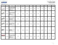
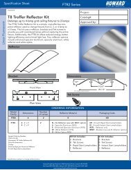
3. Installing the LED COMBO TEST SWITCH (LCTS):<br />
Linear Fixture – Select a convenient location on the fixture so that the LCTS can be seen after installation.<br />
Allow for proper clearance inside the fixture and drill or punch a ½’’ hole. Remove the nut from the LCTS.<br />
Push the LCTS housing into the ½’’ hole and secure with the nut. Connect the wires from the LCTS (VIOLET to<br />
VIOLET, BROWN to BROWN). Refer to figure 1.<br />
Recessed Troffer Fixture – Select a convenient location with proper clearance in the ballast cover and drill<br />
or punch a 7/8’’ bushing into the hole. Push the plastic tube through the bushing. Route the leads of the LED<br />
COMBO SWITCH through the plastic tube. Connect the LED wires from the unit to the switch (Red to Red,<br />
White/Red to White). Push the entire assembly back into the tube until the lens collar rests against the plastic<br />
tube. The plastic tube should be adjusted so that the LED COMBO SWITCH is within ¼’’ of the fixture lens. The<br />
switch must be visible after installation. Refer to figure 2.<br />
Figure 1<br />
Figure 2<br />
Linear Fixture<br />
FIXTURE<br />
LED COMBO<br />
SWITCH<br />
Recessed Troffer Fixture<br />
FIXTURE<br />
EMERGENCY<br />
BALLAST<br />
BALLAST CHANNEL COVER<br />
EMERGENCY BALLAST<br />
BROWN (-)<br />
LEAD<br />
VIOLET (+)<br />
LEAD<br />
OBSERVE PROPER POLARITY<br />
7/8” BUSHING<br />
PLASTIC TUBE<br />
LED COMBO SWITCH<br />
FIXTURE LENS<br />
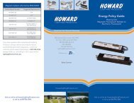
4. Power Supply: The Emergency Ballast and AC ballast must be on the same branch circuit. It requires an<br />
unswitched AC power source of either 120 or 277 volts. Select the proper voltage lead and cap the unused<br />
lead. When the Emergency Ballasts is used with a switched fixture, the AC input to the emergency ballast must<br />
be connected ahead of the fixture switch. Refer to the figure below for switched and unswitched fixture wiring<br />
diagrams.<br />
Figure 3<br />
Ballast Wiring Block Diagram<br />
WALL SWITCH<br />
BLACK<br />
WHITE AC BALLAST<br />
BLACK<br />
WHITE AC BALLAST<br />
LED COMBO SWITCH<br />
HOT AC LINE<br />
COMMON<br />
WHT<br />
*<br />
WHT/BLK<br />
(277V) ORG<br />
(120V) BLK<br />
WHITE<br />
WHT/RED<br />
EMERGENCY<br />
BALLAST<br />
LED COMBO SWITCH<br />
HOT AC LINE<br />
COMMON<br />
WHT<br />
*<br />
WHT/BLK<br />
(277V) ORG<br />
(120V) BLK<br />
WHITE<br />
WHT/RED<br />
EMERGENCY<br />
BALLAST<br />
(+) RED<br />
(+) RED/BLK<br />
OR<br />
RED W/TAG<br />
* Select proper voltage lead. Cap unused lead<br />
(+) RED<br />
(+) RED/BLK<br />
OR<br />
RED W/TAG<br />
* Select proper voltage lead. Cap unused lead<br />
SWITCHED FIXTURE<br />
Specifications subject to change without notice.<br />
UNSWITCHED FIXTURE<br />
Howard Lighting Products | 580 Eastview Drive | Laurel, MS 39443<br />
(toll free) 800.956.3456 | (direct) 601.422.0033 | (fax) 601.422.1652<br />
www.HowardLightingProducts.com