Instruction Sheet
Instruction Sheet
Instruction Sheet

Create successful ePaper yourself
Turn your PDF publications into a flip-book with our unique Google optimized e-Paper software.
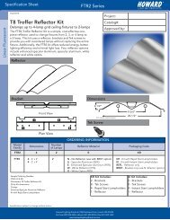
Specification <strong>Sheet</strong><br />
BALT5-500-ACTD<br />
Installation <strong>Instruction</strong>s<br />
Emergency Ballast<br />
When using this lighting device, basic safety precautions should always be followed, including the<br />
following:<br />
READ AND FOLLOW ALL SAFETY INSTRUCTIONS<br />
1. Prior to installation, battery connector must be open to prevent high voltage from being<br />
present on the output leads (red & yellow). It must be connected only after installation is<br />
complete and AC power is supplied to the unit.<br />
2. This device is designed for use with one 2’ to 4’ 8W-28W T5/T5HO, 17W-32W T8, T12 linear<br />
lamp and 4-pin compact fluorescent lamps from 13W-26W. Contact manufacturer for more<br />
information about lamp compatibility.<br />
3. Please ensure the electricity connections conform to the National Electrical Code and local<br />
regulations if applicable.<br />
4. To avoid electrical shock, please disconnect normal and emergency power supplies, and<br />
battery connector of the emergency ballast before servicing.<br />
5. This device is designed for factory or field installation in either the ballast channel or on top<br />
of the fixture, except air handling heated air outlets, sealed and gasketed fixtures, wet or<br />
hazardous location fixtures. Do not install this device near gas or electric heaters.<br />
6. AC Power source of 120 VAC or 277 VAC is required.<br />
7. The battery is sealed, no-maintenance, and is not replaceable in the field. Please contact<br />
manufacturer for information on service. Do not attempt to service the battery.<br />
8. Do not use accessory equipment that is not recommended by manufacturer. Failure to do<br />
so may cause unsafe conditions. Servicing should only be performed by qualified service<br />
personnel.<br />
9. Do not use this product for anything other than it’s intended purpose.<br />
Specifications subject to change without notice.<br />
Howard Lighting Products | 580 Eastview Drive | Laurel, MS 39443<br />
(toll free) 800.956.3456 | (direct) 601.422.0033 | (fax) 601.422.1652<br />
www.HowardLightingProducts.com
Emergency Ballast<br />
Specification <strong>Sheet</strong><br />
BALT5-500-ACTD<br />
Installation <strong>Instruction</strong>s<br />
Caution – Before installing, turn off the main circuit breaker to avoid any possible shock.<br />
Also make sure that the inverter connector is disconnected.<br />
1. Mounting the Emergency Ballast: Remove the ballast channel cover. Mount the Emergency Ballast in the<br />
ballast channel at least ½’’ away from the A.C. ballast(s). When battery packs are remote mounted, the remote<br />
distance can not exceed ½ of the distance from ballast to lamp specified by the AC ballast manufacturer. For<br />
example, if the AC ballast manufacturer recommends no more than 25’ remote distance, then the battery pack<br />
should not exceed 12 ½ ‘. Under no circumstances should the battery pack exceed a distance of 50’ from the<br />
lamp.<br />
2. Wiring: Refer to the wiring diagrams page for the appropriate wiring of lamp(s) and ballast. Install in<br />
accordance with the National Electrical Code and local regulations. For additional wiring diagrams consult<br />
Customer Service.<br />
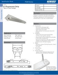
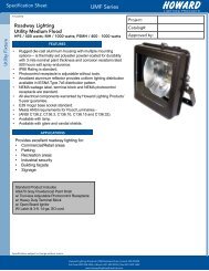
3. Installing the LED COMBO TEST SWITCH (LCTS):<br />
Linear Fixture – Select a convenient location on the fixture so that the LCTS can be seen after installation.<br />
Allow for proper clearance inside the fixture and drill or punch a ½’’ hole. Remove the nut from the LCTS.<br />
Push the LCTS housing into the ½’’ hole and secure with the nut. Connect the wires from the LCTS (VIOLET to<br />
VIOLET, BROWN to BROWN). Refer to figure 1.<br />
Recessed Troffer Fixture – Select a convenient location with proper clearance in the ballast cover and drill<br />
or punch a 7/8’’ bushing into the hole. Push the plastic tube through the bushing. Route the leads of the LED<br />
COMBO SWITCH through the plastic tube. Connect the LED wires from the unit to the switch (Red to Red,<br />
White/Red to White). Push the entire assembly back into the tube until the lens collar rests against the plastic<br />
tube. The plastic tube should be adjusted so that the LED COMBO SWITCH is within ¼’’ of the fixture lens. The<br />
switch must be visible after installation. Refer to figure 2.<br />
Figure 1<br />
Figure 2<br />
Linear Fixture<br />
FIXTURE<br />
LED COMBO<br />
SWITCH<br />
Recessed Troffer Fixture<br />
FIXTURE<br />
EMERGENCY<br />
BALLAST<br />
BALLAST CHANNEL COVER<br />
EMERGENCY BALLAST<br />
BROWN (-)<br />
LEAD<br />
VIOLET (+)<br />
LEAD<br />
OBSERVE PROPER POLARITY<br />
7/8” BUSHING<br />
PLASTIC TUBE<br />
LED COMBO SWITCH<br />
FIXTURE LENS<br />
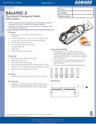
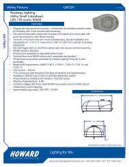
4. Power Supply: The Emergency Ballast and AC ballast must be on the same branch circuit. It requires an<br />
unswitched AC power source of either 120 or 277 volts. Select the proper voltage lead and cap the unused<br />
lead. When the Emergency Ballasts is used with a switched fixture, the AC input to the emergency ballast must<br />
be connected ahead of the fixture switch. Refer to the figure below for switched and unswitched fixture wiring<br />
diagrams.<br />
Figure 3<br />
Ballast Wiring Block Diagram<br />
WALL SWITCH<br />
BLACK<br />
WHITE AC BALLAST<br />
BLACK<br />
WHITE AC BALLAST<br />
LED COMBO SWITCH<br />
HOT AC LINE<br />
COMMON<br />
WHT<br />
*<br />
WHT/BLK<br />
(277V) ORG<br />
(120V) BLK<br />
WHITE<br />
WHT/RED<br />
EMERGENCY<br />
BALLAST<br />
LED COMBO SWITCH<br />
HOT AC LINE<br />
COMMON<br />
WHT<br />
*<br />
WHT/BLK<br />
(277V) ORG<br />
(120V) BLK<br />
WHITE<br />
WHT/RED<br />
EMERGENCY<br />
BALLAST<br />
(+) RED<br />
(+) RED/BLK<br />
OR<br />
RED W/TAG<br />
* Select proper voltage lead. Cap unused lead<br />
(+) RED<br />
(+) RED/BLK<br />
OR<br />
RED W/TAG<br />
* Select proper voltage lead. Cap unused lead<br />
SWITCHED FIXTURE<br />
Specifications subject to change without notice.<br />
UNSWITCHED FIXTURE<br />
Howard Lighting Products | 580 Eastview Drive | Laurel, MS 39443<br />
(toll free) 800.956.3456 | (direct) 601.422.0033 | (fax) 601.422.1652<br />
www.HowardLightingProducts.com
Specification <strong>Sheet</strong><br />
BALT5-500-ACTD<br />
Emergency Ballast<br />
Installation <strong>Instruction</strong>s<br />
5. Labels: Attach the appropriate labels adjacent to the LCTS. Annotate Re-Lamping label for lamp type and<br />
wattage. The ‘Caution’ and the Re-lamping labels must be on the fixture in a readily visible location to anyone<br />
attempting to service the fixture.<br />
6. Completing Installation: When Installation of the ballast is complete, switch the AC power on and join the<br />
emergency ballast’s unit connector.<br />
OPERATION<br />
Normal Mode – When AC power is present, the AC ballast operates the fluorescent lamp(s) as intended. The LCTS<br />
will be lit providing a visual indication that the emergency ballast is being charged.<br />
Emergency Mode – When AC power fails, the LCTS senses the AC power failure and automatically switches to the<br />
Emergency mode. One lamp (or two depending on configuration and ballast) is illuminated, at reduced output, for<br />
a minimum of 90 minutes. When the AC power is restored, the Emergency Ballast switches the system back to the<br />
Normal Mode and resumes battery charging.<br />
TESTING AND MAINTENANCE<br />
Pushing the red lens on the LCTS turns off the light on it, interrupts power to the designated AC ballast and forces<br />
the unit into emergency mode. The emergency lamp(s) is now being lit by the emergency ballast. On releasing the<br />
lens, fixture returns to normal mode after a momentary delay. To simulate a “BLACK OUT” use the circuit breaker<br />
to turn off AC power.<br />
Initial Testing - Allow the unit to charge approximately 1 hour, and then press the LCTS to conduct a short<br />
discharge test. The ballast needs to be charged for at least 24 hours before conducting a 1-1/2 hour test.<br />
This emergency ballast is a maintenance-free unit, however, periodic inspection and testing is required. NFPA 101,<br />
Life Safety Codes, outlines the following schedule:<br />
Monthly – Insure that the LCTS is illuminated. Conduct a 30-second discharge test by depressing the LCTS. One<br />
lamp should operate at reduced output.<br />
Annually - Insure that the LCTS is illuminated. Conduct a full 1-1/2 hour discharge test. The unit should operate as<br />
intended for the duration of the test.<br />
“Written records of testing shall be kept by the owner for inspection by the authority having jurisdiction.”<br />
Specifications subject to change without notice.<br />
Howard Lighting Products | 580 Eastview Drive | Laurel, MS 39443<br />
(toll free) 800.956.3456 | (direct) 601.422.0033 | (fax) 601.422.1652<br />
www.HowardLightingProducts.com
Specification <strong>Sheet</strong><br />
BALT5-500-ACTD<br />
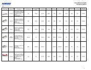
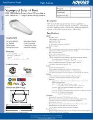
Wiring Diagrams<br />
Contact customer service for wiring diagrams not shown.<br />
Emergency Ballast<br />
1. One Lamp Rapid Start Ballast<br />
BLACK<br />
WHITE<br />
RED<br />
RED<br />
AC<br />
BALLAST<br />
LAMP (emergency)<br />
BLUE<br />
BLUE<br />
BLUE<br />
BLUE/WHT<br />
RED/WHT<br />
RED<br />
YELLOW<br />
EMERGENCY<br />
BALLAST<br />
2 UNIT<br />
CONNECTOR<br />
BROWN (-)<br />
LED<br />
COMBO<br />
SWITCH<br />
VIOLET (+)<br />
3<br />
SWITCHED OR<br />
UNSWITCHED<br />
LINE<br />
ORANGE (277V)<br />
BLACK (120V)<br />
UNSWITCHED 1<br />
WHITE<br />
COMMON<br />
WHT/BLK<br />
1 SELECT PROPER VOLTAGE<br />
LEAD, CAP UNUSED LEAD<br />
2 DO NOT MATE CONNECTOR UNTIL<br />
INSTALLATION IS COMPLETE AND<br />
AC POWER IS SUPPLIED<br />
3 TEST ACCESSORY LEADS,<br />
REFER TO INSTALLATION<br />
INSTRUCTIONS FOR PROPER<br />
POLARITY WIRING<br />
2. Two Lamp Rapid Start Ballast (TypeA)<br />
BLACK<br />
WHITE<br />
YELLOW<br />
YELLOW<br />
AC<br />
BALLAST<br />
LAMP<br />
LAMP (emergency)<br />
BLUE<br />
BLUE<br />
RED<br />
RED<br />
BLUE<br />
BLUE/WHT<br />
RED/WHT<br />
RED<br />
YELLOW<br />
EMERGENCY<br />
BALLAST<br />
UNIT<br />
2 CONNECTOR<br />
BROWN (-)<br />
LED<br />
COMBO<br />
SWITCH<br />
VIOLET (+)<br />
3<br />
SWITCHED OR<br />
UNSWITCHED<br />
LINE<br />
ORANGE (277V)<br />
BLACK (120V)<br />
UNSWITCHED 1<br />
WHITE<br />
COMMON<br />
WHT/BLK<br />
1 SELECT PROPER VOLTAGE<br />
LEAD, CAP UNUSED LEAD<br />
2 DO NOT MATE CONNECTOR UNTIL<br />
INSTALLATION IS COMPLETE AND<br />
AC POWER IS SUPPLIED<br />
3 TEST ACCESSORY LEADS,<br />
REFER TO INSTALLATION<br />
INSTRUCTIONS FOR PROPER<br />
POLARITY WIRING<br />
AC/EMERGENCY<br />
AC/EMERGENCY<br />
3. Two Lamp Rapid Start Ballast (TypeB)<br />
4. Three Lamp Rapid Start Ballast (TypeA)<br />
BLACK<br />
WHITE<br />
YELLOW<br />
YELLOW<br />
AC<br />
BALLAST<br />
BLUE<br />
BLUE<br />
RED<br />
RED<br />
BLUE<br />
BLUE/WHT<br />
RED/WHT<br />
RED<br />
YELLOW<br />
EMERGENCY<br />
BALLAST<br />
SWITCHED OR<br />
UNSWITCHED<br />
LINE<br />
ORANGE (277V)<br />
BLACK (120V)<br />
UNSWITCHED 1<br />
WHITE<br />
COMMON<br />
WHT/BLK<br />
BLACK<br />
WHITE<br />
BLUE<br />
BLUE<br />
YELLOW<br />
YELLOW<br />
AC<br />
BALLAST<br />
BLUE/WHT<br />
BLUE/WHT<br />
RED<br />
RED<br />
BLUE<br />
BLUE/WHT<br />
RED/WHT<br />
RED<br />
YELLOW<br />
EMERGENCY<br />
BALLAST<br />
SWITCHED OR<br />
UNSWITCHED<br />
LINE<br />
ORANGE (277V)<br />
BLACK (120V)<br />
UNSWITCHED 1<br />
WHITE<br />
COMMON<br />
WHT/BLK<br />
LAMP<br />
LAMP (emergency)<br />
UNIT<br />
2 CONNECTOR<br />
BROWN (-)<br />
LED<br />
COMBO<br />
SWITCH<br />
VIOLET (+)<br />
3<br />
1 SELECT PROPER VOLTAGE<br />
LEAD, CAP UNUSED LEAD<br />
2 DO NOT MATE CONNECTOR UNTIL<br />
INSTALLATION IS COMPLETE AND<br />
AC POWER IS SUPPLIED<br />
3 TEST ACCESSORY LEADS,<br />
REFER TO INSTALLATION<br />
INSTRUCTIONS FOR PROPER<br />
POLARITY WIRING<br />
LAMP<br />
LAMP (emergency)<br />
LAMP<br />
UNIT<br />
2 CONNECTOR<br />
BROWN (-)<br />
LED<br />
COMBO<br />
SWITCH<br />
VIOLET (+)<br />
3<br />
1 SELECT PROPER VOLTAGE<br />
LEAD, CAP UNUSED LEAD<br />
2 DO NOT MATE CONNECTOR UNTIL<br />
INSTALLATION IS COMPLETE AND<br />
AC POWER IS SUPPLIED<br />
3 TEST ACCESSORY LEADS,<br />
REFER TO INSTALLATION<br />
INSTRUCTIONS FOR PROPER<br />
POLARITY WIRING<br />
AC/EMERGENCY<br />
AC/EMERGENCY<br />
5. Three Lamp Rapid Start Ballast (TypeB)<br />
6. Four Lamp Rapid Start Ballast<br />
BLACK<br />
WHITE<br />
BLUE<br />
BLUE<br />
BLUE/WHT<br />
BLUE/WHT<br />
AC<br />
BALLAST<br />
LAMP<br />
LAMP (emergency)<br />
LAMP<br />
SWITCHED OR<br />
UNSWITCHED<br />
LINE<br />
RED<br />
BLUE<br />
ORANGE (277V)<br />
RED<br />
BLUE/WHT<br />
BLACK (120V)<br />
UNSWITCHED 1<br />
RED/WHT EMERGENCY<br />
ORANGE<br />
WHITE<br />
ORANGE<br />
RED BALLAST<br />
COMMON<br />
YELLOW<br />
YELLOW<br />
WHT/BLK<br />
YELLOW<br />
BROWN<br />
BROWN 1 SELECT PROPER VOLTAGE<br />
LEAD, CAP UNUSED LEAD<br />
UNIT<br />
2 CONNECTOR<br />
2 DO NOT MATE CONNECTOR UNTIL<br />
INSTALLATION IS COMPLETE AND<br />
AC POWER IS SUPPLIED<br />
LED<br />
3 TEST ACCESSORY LEADS,<br />
COMBO<br />
REFER TO INSTALLATION<br />
SWITCH 3<br />
INSTRUCTIONS FOR PROPER<br />
POLARITY WIRING<br />
BROWN (-)<br />
VIOLET (+)<br />
BLACK<br />
WHITE<br />
BLUE/WHT<br />
BLUE/WHT<br />
ORANGE<br />
ORANGE<br />
AC<br />
BALLAST<br />
LAMP<br />
LAMP<br />
LAMP<br />
LAMP (emergency)<br />
YELLOW<br />
YELLOW<br />
BROWN<br />
BROWN<br />
BLUE<br />
BLUE<br />
RED<br />
RED<br />
BLUE<br />
BLUE/WHT<br />
RED/WHT<br />
RED<br />
YELLOW<br />
EMERGENCY<br />
BALLAST<br />
UNIT<br />
2 CONNECTOR<br />
BROWN (-)<br />
LED<br />
COMBO<br />
SWITCH<br />
VIOLET (+)<br />
3<br />
SWITCHED OR<br />
UNSWITCHED<br />
LINE<br />
ORANGE (277V)<br />
BLACK (120V)<br />
UNSWITCHED 1<br />
WHITE<br />
COMMON<br />
WHT/BLK<br />
1 SELECT PROPER VOLTAGE<br />
LEAD, CAP UNUSED LEAD<br />
2 DO NOT MATE CONNECTOR UNTIL<br />
INSTALLATION IS COMPLETE AND<br />
AC POWER IS SUPPLIED<br />
3 TEST ACCESSORY LEADS,<br />
REFER TO INSTALLATION<br />
INSTRUCTIONS FOR PROPER<br />
POLARITY WIRING<br />
AC/EMERGENCY<br />
AC/EMERGENCY<br />
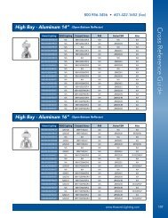
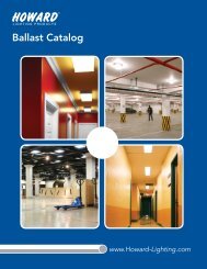
7. One Lamp Instant Start Ballast<br />
8. Two Lamp Instant Start Ballast<br />
BLACK<br />
WHITE<br />
RED<br />
AC<br />
BALLAST<br />
BLUE<br />
3<br />
BLUE<br />
BLUE/WHT<br />
RED/WHT<br />
RED<br />
YELLOW<br />
EMERGENCY<br />
BALLAST<br />
SWITCHED OR<br />
UNSWITCHED<br />
LINE<br />
ORANGE (277V)<br />
BLACK (120V)<br />
UNSWITCHED 1<br />
WHITE<br />
COMMON<br />
WHT/BLK<br />
BLACK<br />
WHITE<br />
RED<br />
AC<br />
BALLAST<br />
BLUE<br />
BLUE<br />
3<br />
BLUE<br />
BLUE/WHT<br />
RED/WHT<br />
RED<br />
YELLOW<br />
EMERGENCY<br />
BALLAST<br />
SWITCHED OR<br />
UNSWITCHED<br />
LINE<br />
ORANGE (277V)<br />
BLACK (120V)<br />
UNSWITCHED 1<br />
WHITE<br />
COMMON<br />
WHT/BLK<br />
LAMP (emergency)<br />
AC/EMERGENCY<br />
UNIT<br />
2 CONNECTOR<br />
BROWN (-)<br />
LED<br />
COMBO<br />
SWITCH<br />
VIOLET (+)<br />
4<br />
1 SELECT PROPER VOLTAGE<br />
LEAD, CAP UNUSED LEAD<br />
2 DO NOT MATE CONNECTOR UNTIL<br />
INSTALLATION IS COMPLETE AND<br />
AC POWER IS SUPPLIED<br />
3 CONNECT BLUE/WHT AND RED/WHT<br />
WIRES TOGETHER<br />
4 TEST ACCESSORY LEADS,<br />
REFER TO INSTALLATION<br />
INSTRUCTIONS FOR PROPER<br />
POLARITY WIRING<br />
LAMP<br />
LAMP (emergency)<br />
AC/EMERGENCY<br />
UNIT<br />
2 CONNECTOR<br />
BROWN (-)<br />
LED<br />
COMBO<br />
SWITCH<br />
VIOLET (+)<br />
4<br />
1 SELECT PROPER VOLTAGE<br />
LEAD, CAP UNUSED LEAD<br />
2 DO NOT MATE CONNECTOR UNTIL<br />
INSTALLATION IS COMPLETE AND<br />
AC POWER IS SUPPLIED<br />
3 CONNECT BLUE/WHT AND RED/WHT<br />
WIRES TOGETHER<br />
4 TEST ACCESSORY LEADS,<br />
REFER TO INSTALLATION<br />
INSTRUCTIONS FOR PROPER<br />
POLARITY WIRING<br />
9. Three Lamp Instant Start Ballast<br />
10. Four Lamp Instant Start Ballast<br />
BLACK<br />
WHITE<br />
RED<br />
AC<br />
BALLAST<br />
BLUE<br />
BLUE<br />
BLUE<br />
3<br />
BLUE<br />
BLUE/WHT<br />
RED/WHT<br />
RED<br />
YELLOW<br />
EMERGENCY<br />
BALLAST<br />
SWITCHED OR<br />
UNSWITCHED<br />
LINE<br />
ORANGE (277V)<br />
BLACK (120V)<br />
UNSWITCHED 1<br />
WHITE<br />
COMMON<br />
WHT/BLK<br />
BLACK<br />
WHITE<br />
YELLOW<br />
YELLOW<br />
AC<br />
BALLAST<br />
BLUE<br />
BLUE<br />
RED<br />
RED<br />
3<br />
BLUE<br />
BLUE/WHT<br />
RED/WHT<br />
RED<br />
YELLOW<br />
EMERGENCY<br />
BALLAST<br />
SWITCHED OR<br />
UNSWITCHED<br />
LINE<br />
ORANGE (277V)<br />
BLACK (120V)<br />
UNSWITCHED 1<br />
WHITE<br />
COMMON<br />
WHT/BLK<br />
LAMP<br />
LAMP<br />
LAMP (emergency)<br />
AC/EMERGENCY<br />
UNIT<br />
2 CONNECTOR<br />
BROWN (-)<br />
LED<br />
COMBO<br />
SWITCH<br />
VIOLET (+)<br />
4<br />
1 SELECT PROPER VOLTAGE<br />
LEAD, CAP UNUSED LEAD<br />
2 DO NOT MATE CONNECTOR UNTIL<br />
INSTALLATION IS COMPLETE AND<br />
AC POWER IS SUPPLIED<br />
3 CONNECT BLUE/WHT AND RED/WHT<br />
WIRES TOGETHER<br />
4 TEST ACCESSORY LEADS,<br />
REFER TO INSTALLATION<br />
INSTRUCTIONS FOR PROPER<br />
POLARITY WIRING<br />
LAMP<br />
LAMP<br />
LAMP<br />
LAMP (emergency)<br />
AC/EMERGENCY<br />
UNIT<br />
2 CONNECTOR<br />
BROWN (-)<br />
LED<br />
COMBO<br />
SWITCH<br />
VIOLET (+)<br />
4<br />
1 SELECT PROPER VOLTAGE<br />
LEAD, CAP UNUSED LEAD<br />
2 DO NOT MATE CONNECTOR UNTIL<br />
INSTALLATION IS COMPLETE AND<br />
AC POWER IS SUPPLIED<br />
3 CONNECT BLUE/WHT AND RED/WHT<br />
WIRES TOGETHER<br />
4 TEST ACCESSORY LEADS,<br />
REFER TO INSTALLATION<br />
INSTRUCTIONS FOR PROPER<br />
POLARITY WIRING<br />
Specifications subject to change without notice.<br />
Howard Lighting Products | 580 Eastview Drive | Laurel, MS 39443<br />
(toll free) 800.956.3456 | (direct) 601.422.0033 | (fax) 601.422.1652<br />
www.HowardLightingProducts.com