PM-7 Operating Manua.. - Voss Associates
PM-7 Operating Manua.. - Voss Associates
PM-7 Operating Manua.. - Voss Associates

You also want an ePaper? Increase the reach of your titles
YUMPU automatically turns print PDFs into web optimized ePapers that Google loves.
. Scintillator Installation<br />
Introduction<br />
Overview<br />
Install the scintillators column by column, being careful to note<br />
their numbered locations. Each scintillator features a number on its<br />
side that corresponds with the number on the detector. For example,<br />
the #5 scintillator would be the bottom right side and corresponds<br />
with #5 on the detector. The next section describes the assembly<br />
procedures for installing lead shielding and scintillators.<br />
Slide the bottom scintillator into its slot with the coaxial connector<br />
on the same side as the coaxial cable. Hold the bottom scintillator<br />
still. Slip a z-bracket, supplied separately (Part No.<br />
610KZ081--01-360 REV AV1), around the back and bottom of the<br />
top scintillator. The hollow portion of the bracket should be<br />
pointing downwards. Place the top pointing and<br />
bracket in the top bay area, such that the<br />
scintillator's bottom edge is high enough to clear the<br />
metal lip at the bottom of its bay. Lower the<br />
scintillator until it rests on the bay ledge. The<br />
z-bracket is held in place by the upper scintillator<br />
and secures the lower detector. Attach the coaxial<br />
cables to the scintillators and ensure that each cable's<br />
service loop is tucked out of the way. Replace the<br />
Lead scintillator access panels and secure the locks.<br />
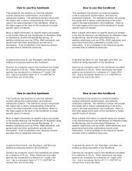
Angle<br />
Bracket<br />
Figure 1.4. Head Detector and Lead Assembly<br />
Scintillator<br />
Foam<br />
3. Installation of the Head Scintillator (#1) and its<br />
Lead Shielding<br />
On the inside of the head scintillator area, you<br />
should see a piece of foam with 2 brackets on its<br />
sides. Loosen the brackets. Place the head scintillator<br />
(#1) flat on the foam, orienting the detector coaxial<br />
connector with the protruding cable. Install the<br />
smallest pieces of lead to the bracket in the same way<br />
that corresponding pieces are installed in the foot<br />
scintillator pan.<br />
Find the two shortest, slotted pieces of lead. Place<br />
these along the longer side of the detector, slot facing<br />
upwards. Put the four separately packaged corner<br />
brackets on the four corners of the lead assembly.<br />
Connect the scintillator's coaxial connector to the<br />
cable. Place the last lead piece, which is the same size<br />
as the larger pieces used in the columns except that it<br />
Thermo Fisher Scientific<br />
<strong>PM</strong> -7 Manager User’s Guide_1-5_