PM-7 Operating Manua.. - Voss Associates
PM-7 Operating Manua.. - Voss Associates
PM-7 Operating Manua.. - Voss Associates

Create successful ePaper yourself
Turn your PDF publications into a flip-book with our unique Google optimized e-Paper software.
<strong>PM</strong>-7.Man<br />
Rev. C<br />
Personnel Monitor-7<br />
<strong>PM</strong>-7<br />
Technical <strong>Manua</strong>l
© 2008 Thermo Fisher Scientific Inc. All rights reserved.<br />
Microsoft is either registered trademarks or trademarks of Microsoft in the United States and/or other countries.<br />
iPod ® is a registered trademark of Apple ® .<br />
Other trademarks and trade names may be used in this document to refer to either the entities claiming the marks<br />
and names or their products.
Definition of Terms<br />
Writing Conventions<br />
This manual follows certain writing conventions that are listed below for<br />
your convenience.<br />
• When a specific operating system command, file name, directory<br />
name or environment variable is used in the text, it is shown in small<br />
caps; for example, C:\NVLAP\NVLAP.EXE<br />
When describing software, such as WinREMS SQL, Thermo Scientific uses<br />
the following conventions:<br />
• Screen Names, Pull-Down Menu Selections, and Field Names are<br />
always capitalized; for example, Main Menu Screen or Input File<br />
Field.<br />
• Data Field Entries and Multiple Choice (pop-up) Field Selections<br />
are enclosed in single quotes; for example, ‘neutron’.<br />
• Graphical User Interface commands and Keyboard keys (other than<br />
letters, numbers, and punctuation) are shown with the “greater<br />
than” symbol(>) followed by the command in Bold text.<br />
Safety Warnings<br />
Thermo Scientific manuals feature safety warnings, cautionary statements,<br />
and other admonitions designed to alert readers. All admonitions begin with<br />
“Note” or “Caution” and end with a triangular slug: ▲<br />
• CAUTION indicates a potentially hazardous situation which, if not<br />
avoided, may result in minor or moderate injury. It may also be used<br />
to alert against unsafe practices. CAUTION notices always appear in<br />
bold, italicized letters.<br />
• NOTE indicates a situation which has the potential for erroneous<br />
data collection, loss of electronic data, or damage to equipment, but<br />
which does not directly affect the safety of the operator with respect<br />
to this product. The responsibility for any safety consequences as a<br />
result of erroneous data lies solely with the operator. Notes always<br />
appear with the word “Note” at the beginning of the paragraph.<br />
Thermo Fisher Scientific Personnel Monitor -7 Techical Guide _ iii
Safety Warnings<br />
European Notice<br />
Products with the CE Marking (Figure 0.2) comply<br />
with the EMC directive (89/336/EEC) issued by the<br />
Commission of the European Community.<br />
Figure CE.1. CE<br />
Compliance Marking<br />
Compliance with the directive implies conformity to the following<br />
European Standards:<br />
EN 55011:1991 Limits and methods of measurement of radio<br />
disturbance characteristics of industrial, scientific and medical (ISM)<br />
radio frequency equipment. (Emission standard)<br />
EN50082-1:1994 Electromagnetic compatibility - Generic immunity<br />
standard.<br />
Table CE-1. Test Procedures and Description<br />
Test Procedure Description<br />
55011 Conducted Emissions<br />
55011 Radiated Emissions<br />
61000-3-3 Voltage Fluctuation and Flicker Tests<br />
61000-3-2 Current Harmonics Test<br />
61000-4-2 Electrostatic Discharge<br />
61000-4-3 Radiated Immunity<br />
61000-4-4 Fast Burst Transients<br />
61000-4-5 Surge<br />
61000-4-6 Conducted Immunity<br />
61000-4-11 Voltage Dips/Interruptions<br />
EN 61010-1: 1990 Safety requirements for electrical equipment for<br />
measurement, control, and laboratory use.<br />
iv _Personnel Monitor -7 Techical Guide<br />
Thermo Fisher Scientific
WEEE Compliance<br />
WEEE Compliance<br />
Note In order for the instrument to comply with the standards, as tested, the<br />
following must be adhered to:<br />
The front panel Access Doors should not be opened while in Read or<br />
Expose Modes. ▲<br />
The following maximum cable lengths must be observed:<br />
• AC Power - 3.0 meters (10 ft.). ▲<br />
• UPS Input - 3.0 meters (10 ft.). ▲<br />
• Serial - 7.5 meters (25 ft.). ▲<br />
• Parallel - 3.0 meters (10 ft.). ▲<br />
Thermo Fisher Scientific has contracted with one or more<br />
recycling/disposal companies in each EU Member State, and<br />
this product should be disposed of or recycled through them.<br />
Further information on Thermo Fisher Scientific’s compliance<br />
with these Directives, the recyclers in your country, and<br />
information on Thermo Fisher Scientific products which may<br />
assist the detection of substances subject to the RoHS Directive are available<br />
at www.thermo.com/WEEERoHS.<br />
Thermo Fisher Scientific Personnel Monitor -7 Techical Guide v_
WEEE Compliance<br />
vi _Personnel Monitor -7 Techical Guide<br />
Thermo Fisher Scientific
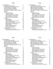
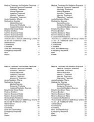
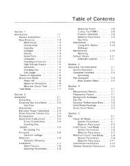
Contents<br />
Definition of Terms .................................................................iii<br />
Writing Conventions..................................................................iii<br />
Safety Warnings .........................................................................iii<br />
European Notice ...................................................................... iv<br />
WEEE Compliance.....................................................................v<br />
Chapter 1<br />
Installation and Setup............................................................1-1<br />
Overview................................................................................. 1-1<br />
Unpacking the <strong>PM</strong>-7 ........................................................... 1-2<br />
Chapter 2<br />
Operational Setup..................................................................2-1<br />
Configuration ......................................................................... 2-1<br />
Optional Remote Annunciator Installation .......................... 2-4<br />
Chapter 3<br />
General Description...............................................................3-1<br />
Overview................................................................................. 3-1<br />
Features................................................................................... 3-2<br />
Specifications .......................................................................... 3-2<br />
Detectors................................................................................. 3-3<br />
Audible Annunciators ............................................................. 3-3<br />
Operational Parameters ........................................................... 3-3<br />
Operation ............................................................................... 3-4<br />
Background Updating Routine................................................ 3-5<br />
Chapter 4<br />
Algorithms.............................................................................4-1<br />
Counting Algorithms .............................................................. 4-1<br />
Statistical Theory .................................................................... 4-2<br />
Guide to Figures 4.2, 4.3 and 4.4............................................ 4-6<br />
Thermo Fisher Scientific<br />
Model 8800 PLUS TLD Reader with WinREMS SQL Operator’s <strong>Manua</strong>l_vii
Chapter 5 PC-Based Calibration/Configuration Program ......................5-1<br />
Windows-Based Software ........................................................ 5-1<br />
MS-DOS or PC-DOS General Description ......................... 5-1<br />
Overview.............................................................................. 5-1<br />
Starting the Program ............................................................ 5-2<br />
General Conventions ........................................................... 5-3<br />
Menu Item Description........................................................ 5-4<br />
Connect ............................................................................ 5-4<br />
Disk Edit........................................................................... 5-9<br />
Reports ........................................................................... 5-10<br />
Quit................................................................................ 5-11<br />
Chapter 6<br />
Maintenance..........................................................................6-1<br />
Preventative Maintenance........................................................ 6-1<br />
Setting Low Voltage ............................................................. 6-1<br />
Batteries ............................................................................... 6-1<br />
Calibration........................................................................... 6-1<br />
Plateaus............................................................................. 6-2<br />
Efficiencies........................................................................ 6-2<br />
Shield Factors.................................................................... 6-3<br />
Documentation................................................................. 6-3<br />
Diagnostics ....................................................................... 6-3<br />
Troubleshooting ...................................................................... 6-5<br />
Instrument is out of service .................................................. 6-5<br />
High Background Condition............................................. 6-5<br />
Communication Failure .................................................... 6-5<br />
Board or Detector Repair ..................................................... 6-6<br />
Loss of AC Power................................................................. 6-6<br />
Recommended <strong>Operating</strong> Parameters...................................... 6-7<br />
Chapter 7 <strong>PM</strong>-7 Microcomputer Hardware Complement Sheet —<br />
Customer Standard Document NO. 17000-A617-1<br />
General Description ................................................................ 7-1<br />
On Board Functions................................................................ 7-1<br />
Theory of Operation............................................................... 7-2<br />
Microcomputer and Associated Circuits............................... 7-2<br />
Serial Communication ......................................................... 7-2<br />
I/O Functions ...................................................................... 7-3<br />
Voltage Supplies and Regulators ........................................... 7-3<br />
Program Running Light ....................................................... 7-3<br />
Routine Maintenance........................................................... 7-4<br />
Calibration.............................................................................. 7-4<br />
viii _Model 8800 PLUS TLD Reader with WinREMS SQL Operator’s <strong>Manua</strong>l<br />
Thermo Fisher Scientific
Troubleshooting ...................................................................... 7-4<br />
EPROM Program ................................................................ 7-4<br />
Remaining Faults - Processor Running ................................. 7-4<br />
Parts List ................................................................................. 7-6<br />
Electronic Items Incorporated in Master Controller Board... 7-6<br />
Chapter 8<br />
General Purpose Detector Board YP11454002......................8-1<br />
General Description ................................................................ 8-1<br />
Theory of Operation............................................................... 8-2<br />
Microcomputer and Associated Circuits............................... 8-2<br />
Detector Control and Associated Circuits ............................ 8-2<br />
Speaker and Alarm Outputs ................................................. 8-3<br />
Maintenance ........................................................................... 8-3<br />
Routine Maintenance........................................................... 8-3<br />
Calibration.............................................................................. 8-3<br />
High Voltage........................................................................ 8-3<br />
Discriminator....................................................................... 8-4<br />
Troubleshooting ...................................................................... 8-5<br />
Parts List ................................................................................. 8-6<br />
Chapter 9 RS-485 Driver Board YP11455002 .......................................9-1<br />
General Description ................................................................ 9-1<br />
Theory of Operation............................................................... 9-1<br />
Maintenance ........................................................................... 9-1<br />
Routine Maintenance........................................................... 9-1<br />
Troubleshooting ................................................................... 9-1<br />
Checkout ............................................................................. 9-1<br />
Parts List ................................................................................. 9-2<br />
Chapter 10 Dual Channel Ultrasonic Ranging Board.............................10-1<br />
General Description .............................................................. 10-1<br />
Theory of Operation............................................................. 10-1<br />
Transmit Circuit................................................................. 10-1<br />
Receive Circuit................................................................... 10-2<br />
Sonar Ranging Control ...................................................... 10-2<br />
Transmit/Receive Device Cycle .......................................... 10-2<br />
Maintenance ......................................................................... 10-3<br />
Routine Maintenance......................................................... 10-3<br />
Calibration......................................................................... 10-3<br />
Troubleshooting ................................................................. 10-3<br />
Parts List ............................................................................... 10-5<br />
Thermo Fisher Scientific<br />
Model 8800 PLUS TLD Reader with WinREMS SQL Operator’s <strong>Manua</strong>l_ix
Chapter 11 RS-232 to RS-485 Converter Board ....................................11-1<br />
General Description .............................................................. 11-1<br />
Theory of Operation............................................................. 11-1<br />
Special Functions .................................................................. 11-2<br />
Parts List ............................................................................... 11-3<br />
Chapter 12 Large Area Plastic Scintillation Detectors ............................12-1<br />
General Description .............................................................. 12-1<br />
Specifications ........................................................................ 12-1<br />
Theory of Operation............................................................. 12-1<br />
Maintenance ......................................................................... 12-2<br />
Chapter 13 Miscellaneous Parts..............................................................13-1<br />
Parts not Specified in Subassembly Sections .......................... 13-1<br />
Chapter 14 Options ...............................................................................14-1<br />
Remote Annunciator............................................................. 14-1<br />
Calibration Computer........................................................... 14-1<br />
Traffic Barrier........................................................................ 14-1<br />
Calibration Jig....................................................................... 14-1<br />
RS-232 Cable........................................................................ 14-1<br />
Parallel/Serial Printer............................................................. 14-2<br />
Chapter 15 Recommended Spare Parts...................................................15-1<br />
Appendix A Technical Support .................................................................. A-1<br />
Technical Support Contact Information..................................A-1<br />
Worldwide ...........................................................................A-1<br />
United Kingdom..................................................................A-1<br />
United States........................................................................A-1<br />
Appendix B Thermo Scientific Sales and Support Contact Information.... B-1<br />
Appendix C Drawings ...............................................................................C-1<br />
x _Model 8800 PLUS TLD Reader with WinREMS SQL Operator’s <strong>Manua</strong>l<br />
Thermo Fisher Scientific
Figures<br />
CE Compliance Marking ...........................................................................................xii<br />
Unpack the monitor and place in intended location ................................................1-1<br />
<strong>PM</strong>-7 shipped in Horizontal Position ........................................................................1-2<br />
Side Column Lead Assembly ....................................................................................1-4<br />
Head Detector and Lead Assembly ..........................................................................1-5<br />
Model for Radiological Movements ........................................................................4-2<br />
Sigma Factor Nomograph, 11468-C176 ...................................................................4-7<br />
<strong>PM</strong>-7 Response to 60Co, 11468-C175 .....................................................................4-8<br />
<strong>PM</strong>-7 Response to 137Cs, 11468-C174A .................................................................4-9<br />
Thermo Fisher Scientific <strong>PM</strong>-7 Calibration Program ...............................................5-3<br />
Thermo Fisher Scientific <strong>PM</strong>-7 Calibration Program (submenu)...............................5-5<br />
Statistical Limits of Counter Reliability ...................................................................6-4<br />
Thermo Fisher Scientific<br />
Model 8800 PLUS TLD Reader with WinREMS SQL Operator’s <strong>Manua</strong>l_xi
Tables<br />
Test Procedures and Description............................................................................. xii<br />
Probability Distribution Channel .............................................................................4-4<br />
<strong>PM</strong>-7 Microcomputer Hardware Complement Sheet Parts List .............................7-6<br />
General Purpose Detector Board YP11454002 Parts List .......................................8-6<br />
Complete Board Assembly, YP11455002 Parts List ...............................................9-2<br />
Dual Channel Ultrasonic Ranging Brd Parts List ........................................................ 10-5<br />
Baud Rate Selection SW1 - 4 .................................................................................10-1<br />
RS 232 to RS 485 Interface, YP11451000 ..............................................................11-3<br />
Large Area Plastic Scintillation Detectors .............................................................12-3<br />
Miscellaneous Parts ...............................................................................................13-1<br />
Option Part Numbers ............................................................................................... 14-2<br />
Recommended Spare Parts ....................................................................................15-1<br />
<strong>PM</strong>-7 Drawings .......................................................................................................C-1<br />
xii _Model 8800 PLUS TLD Reader with WinREMS SQL Operator’s <strong>Manua</strong>l<br />
Thermo Fisher Scientific
Chapter 1 Installation and Setup<br />
Overview<br />
Immediately after unpacking the monitor, inspect it for external damage.<br />
CAUTION <strong>PM</strong>-7 scintillators are delicate and must be handled with care to<br />
prevent jarring. Place the scintillator on a padded surface free of objects or<br />
materials that could damage the protective wrapping. A detector should be laid<br />
flat on a large surface. Do not stack or place anything on the detector. ▲<br />
If the <strong>PM</strong>-7 is shipped in a horizontal position:<br />
-<br />
1. Place the monitor in its<br />
intended location and<br />
unpack it.<br />
2. The monitor ramp must<br />
be installed after the<br />
monitor is in position. All<br />
ramp support pieces are<br />
removable and designed to<br />
allow staff to move the<br />
monitor through a<br />
doorway.<br />
3. If these side pieces must be<br />
removed, begin by taking<br />
off the 1/4-20 hardware<br />
which holds the supports<br />
to the bottom of the<br />
monitor.<br />
Figure 1.1. Unpack the monitor and place it<br />
in the intended location<br />
4. This will be two hex bolts<br />
and two carriage bolts with nuts on each side of the monitor.<br />
5. Once the monitor is in position, reinstall the side support pieces. The<br />
ramp will be installed later.<br />
Thermo Fisher Scientific <strong>PM</strong> -7 Manager User’s Guide_ 1-1
Introduction<br />
Overview<br />
Unpacking the <strong>PM</strong>-7<br />
1. Place the <strong>PM</strong>-7 monitor's<br />
box on its side on a flat<br />
surface, so that its longest<br />
side is parallel to the flat<br />
surface. The box's cover<br />
bolts, 3/8” (96.52 mm) hex<br />
heads by 1 1/2” (38.1 mm)<br />
long, should be located<br />
around the bottom<br />
circumference of the box.<br />
2. Remove all 3/8” (96.52<br />
mm) hex heads.<br />
3. Raise and remove box<br />
cover.<br />
4. A board frame surrounds<br />
the bottom of the monitor.<br />
Find the shorter sided<br />
board attached with the<br />
three 1/4” (6.35 mm) hex<br />
head lag screws.<br />
Figure 1.2. <strong>PM</strong>-7 shipped in Horizontal<br />
Position<br />
5. Remove the 3 bolts and the board.<br />
CAUTION The <strong>PM</strong>-7 monitor shipping weight exceeds 1000 pounds (454 k).<br />
The <strong>PM</strong>-7 using proper lifting techniques approved by your organization’s<br />
safety regulations, safety officer or supervisor. ▲<br />
-<br />
6. Slide the monitor along the bottom of the box through this newly<br />
created hole.<br />
7. Place the monitor top side up.<br />
8. Remove all packing material and inspect the monitor for internal<br />
damage.<br />
9. All scintillators and lead shielding, excluding the foot lead shielding, are<br />
shipped separately from the <strong>PM</strong>-7.<br />
1-2 _<strong>PM</strong> -7 Manager User’s Guide Thermo Fisher Scientific
Introduction<br />
Overview<br />
If the <strong>PM</strong>-7 is shipped in a vertical position:<br />
Move the <strong>PM</strong>-7 with a heavy-duty hand truck (dolly) and strapping.<br />
1. Installation of the Foot Detector<br />
Pull out all the packing material around the lead shielding. Connect the<br />
foot scintillator to its coaxial cable. Place the foot scintillator flat on the<br />
bottom rectangular piece of lead, aligning the scintillator's coaxial<br />
connector with the coaxial cable entry hole. Place the ramp on the<br />
monitor.<br />
2. Installation of the Side Detectors (#4 and #5 bottom, #2 and #3 top)<br />
and their Lead Shielding<br />
The side scintillators will be located behind the large, flat panels that are<br />
between the beveled edges of the <strong>PM</strong>-7 columns. After they are<br />
unlocked, the panels are removed by rotating the top edge away from<br />
the column and raising the bottom off of two locating pins.<br />
a. Lead Installation<br />
The side assembly requires three sizes of lead:<br />
• Long, slender pieces<br />
• Long slender pieces with notches<br />
• Pieces with four mounting holes.<br />
The long, slender pieces of lead are to be mounted at the sides of the<br />
detector bays. Complete the installation of lead shielding in one<br />
side's lower bay before starting the upper bay.<br />
Place the notched edge of the lead shield so that in coincides with<br />
the notch that has the detector cable installed in it, notch pointing<br />
outward.<br />
The scintillator back is shielded with two of the large plates that<br />
have holes drilled in them. Place the first one at the bottom of the<br />
bay, between the side pieces of lead, and so the holes line up with<br />
threaded inserts in the frame. Secure the three pieces of lead with<br />
two of the angle brackets before stacking the second plate with holes<br />
on top of the first. The angle brackets (16 in total) and mounting<br />
screws (1/4-20 x 1-1/4” 1 long flatter supplied in a separate box.<br />
1 1-1/4” is equal to 31.75 mm<br />
Thermo Fisher Scientific<br />
<strong>PM</strong> -7 Manager User’s Guide_1-3_
Introduction<br />
Overview<br />
Secure the second plate with two angle brackets. lead in the upper<br />
bay, then install the lead for the other side in similar fashion. See<br />
Figure 1.3 for a pictorial view of a side's lead assembly.<br />
Lead<br />
Secure Pieces<br />
of Lead with<br />
Angle Bracket<br />
Figure 1.3. Side Column Lead Assembly<br />
1-4 _<strong>PM</strong> -7 Manager User’s Guide Thermo Fisher Scientific
. Scintillator Installation<br />
Introduction<br />
Overview<br />
Install the scintillators column by column, being careful to note<br />
their numbered locations. Each scintillator features a number on its<br />
side that corresponds with the number on the detector. For example,<br />
the #5 scintillator would be the bottom right side and corresponds<br />
with #5 on the detector. The next section describes the assembly<br />
procedures for installing lead shielding and scintillators.<br />
Slide the bottom scintillator into its slot with the coaxial connector<br />
on the same side as the coaxial cable. Hold the bottom scintillator<br />
still. Slip a z-bracket, supplied separately (Part No.<br />
610KZ081--01-360 REV AV1), around the back and bottom of the<br />
top scintillator. The hollow portion of the bracket should be<br />
pointing downwards. Place the top pointing and<br />
bracket in the top bay area, such that the<br />
scintillator's bottom edge is high enough to clear the<br />
metal lip at the bottom of its bay. Lower the<br />
scintillator until it rests on the bay ledge. The<br />
z-bracket is held in place by the upper scintillator<br />
and secures the lower detector. Attach the coaxial<br />
cables to the scintillators and ensure that each cable's<br />
service loop is tucked out of the way. Replace the<br />
Lead scintillator access panels and secure the locks.<br />
Angle<br />
Bracket<br />
Figure 1.4. Head Detector and Lead Assembly<br />
Scintillator<br />
Foam<br />
3. Installation of the Head Scintillator (#1) and its<br />
Lead Shielding<br />
On the inside of the head scintillator area, you<br />
should see a piece of foam with 2 brackets on its<br />
sides. Loosen the brackets. Place the head scintillator<br />
(#1) flat on the foam, orienting the detector coaxial<br />
connector with the protruding cable. Install the<br />
smallest pieces of lead to the bracket in the same way<br />
that corresponding pieces are installed in the foot<br />
scintillator pan.<br />
Find the two shortest, slotted pieces of lead. Place<br />
these along the longer side of the detector, slot facing<br />
upwards. Put the four separately packaged corner<br />
brackets on the four corners of the lead assembly.<br />
Connect the scintillator's coaxial connector to the<br />
cable. Place the last lead piece, which is the same size<br />
as the larger pieces used in the columns except that it<br />
Thermo Fisher Scientific<br />
<strong>PM</strong> -7 Manager User’s Guide_1-5_
Introduction<br />
Overview<br />
doesn't have holes, on top of the 4 corner brackets. See Figure 1.4 for a<br />
pictorial view of the head detector and lead assembly. Replace both the top<br />
cover and the foot cover.<br />
1-6 _<strong>PM</strong> -7 Manager User’s Guide Thermo Fisher Scientific
Chapter 2 Operational Setup<br />
Configuration<br />
Note If the portal monitor is to have power supplied in conduit, install conduit<br />
at this point. Holes are provided at the right-hand rear corner at the top of the<br />
instrument for installation of 3/4” (19.05 mm) nominal conduit fittings. ▲<br />
-<br />
The portal (<strong>PM</strong>-7) is flexible and can be configured in several ways. These<br />
include portal address, walk-thru operation, use of photoelectric switch, use<br />
of ultrasonic occupied signal and the tone-on-start of count cycle.<br />
Each of these items is selected (enabled or disabled), depending upon the<br />
position of the switches (SW1 and SW2) on the Master Annunciator<br />
printed circuit board.<br />
These switches contain eight individual rocker switches (1-8). The functions<br />
are ad indicated in the following figure. These switches are physically<br />
located near one end of the Master Annunciator printed circuit board, SWl<br />
is nearest to the center of the board.<br />
Portal Addressing:<br />
When several portals are installed at one facility, each should be given a<br />
unique address. By doing so the files kept by the portable laptop computer<br />
will be identified to each portal. Set the desired address of the portal by<br />
selecting the binary pattern of SW-1 switches 5 through 8 (SW-15-8).<br />
Walk-through Operation:<br />
The portal may be operated in one of two modes, Walk-through or pause<br />
and be counted. If the operating parameters are compatible with walt-thru<br />
operation, then use of the walk-thru mode is appropriate and switch SW2-1<br />
should be open. If however, the count time is excessive a pause and be<br />
counted mode may be more appropriate.<br />
The count time in the walk-thru mode should be such that the individual<br />
will e counted at least once, if not twice, as the individual walks at a normal<br />
speed through the monitor.<br />
If switch SW2-1 is closed then the monitor operates in a pause and be<br />
counted mode, requiring the individual to remain in the portal for a<br />
complete count cycle. The chime is used in this mode to signal the end of<br />
the count cycle. This notifies the individual that he may exit.<br />
Thermo Fisher Scientific Personnel Monitor -7 Techical Guide_ 2-1
Introduction<br />
Configuration<br />
Photoelectric Switch:<br />
An infrared photoelectric light beam (switch) is located to scan across the<br />
center of the portal at about waist height. The beam goes from one column<br />
diagonally across the other column. This beam detects the physical presence<br />
of the individual but may be disabled by opening SW2-2. If the<br />
photoelectric switch is disabled the ultrasonic occupied signal must be<br />
enabled.<br />
Ultrasonic Occupied Signal<br />
The <strong>PM</strong>-7 uses an ultrasonic ranging device to determine when a person is<br />
near the unit and when the unit is occupied. In some cases the sensor may<br />
not detect an individual when they are within the unit. This is the case with<br />
very tall individuals. The photoelectric light beam was added to ensure an<br />
individual was present in the unit. Non the less, switch SW2-3 maybe closed<br />
to disable the ultrasonic occupied signal. If the ultrasonic occupied signal is<br />
disabled the photoelectric switch must be enabled.<br />
Beginning of Count Cycle Tone<br />
Switch SW2-4 is open to enable a time (chime) at the beginning of a count<br />
cycle. Closing the switch disables this feature.<br />
Connect the laptop computer to the <strong>PM</strong>-7 with the serial interface cable.<br />
The cable will connect to serial port COM1: on the computer and to the<br />
DB-9 connector on one of the four hinged doors of the <strong>PM</strong>-7. For<br />
reference, that door will hereinafter be called the “right-hand aft” door.<br />
Boot the computer up. If the computer used does not have DOS installed in<br />
ROM or on a hard disk, a DOS system disk will be needed in order to boot<br />
the computer. Verify that the correct date is in the system by invoking the<br />
“Date” command. This is very important because the calibration program<br />
reads the date from the operating system's clock and uses that information<br />
to decay-correct calibration source activity. With the <strong>PM</strong>-7 Program disk in<br />
the default drive initiate the calibration program by typing > <strong>PM</strong>-7. To<br />
execute a command from the menu bar on the computer screen either type<br />
the first letter of the command and press > RETURN or > ENTER, or use<br />
the cursor keys (arrows) to move the reverse-video highlight to the desired<br />
command and press > ENTER. Select PASSWORD from the menu bar;<br />
enter the password “Eberline” to access the program. Do not attempt to<br />
connect until the <strong>PM</strong>-7 is powered up.<br />
Note The password is set at the factory to be Eberline. ▲<br />
2-2 _Personnel Monitor -7 Techical Guide Thermo Fisher Scientific
Introduction<br />
Configuration<br />
Select > DISK EDIT from the main menu by scrolling to DISK EDIT and<br />
striking > ENTER. This could have been accomplished by pressing “D”<br />
then > ENTER. In the following text the technique to select commands will<br />
be scrolling to the command then pressing > ENTER. The alternate<br />
method of typing the first key of the command works equally well. This<br />
technique has been omitted to keep the text brief. From the submenu scroll<br />
to SYSTEM and strike > ENTER to display the existing system parameters.<br />
Review the parameters and adjust them as desired. To edit a field, position<br />
the cursor over the field to be editing by moving it with the cursor control<br />
(arrow) keys and then strike > F1. Enter information pertinent to the<br />
calibration sources that will be used in the appropriate fields. The source<br />
activity that is entered should be the activity as of the calibration date that is<br />
entered; the decay-corrected activity is automatically computed. If a source<br />
that is comprised of a mixture of two isotopes will be used, enter the<br />
information for each isotope on a separate line as though they were<br />
individual sources.<br />
When all system parameters are set as desired, strike > F2 to save the<br />
parameters to the disk and exit the routine.<br />
From the submenu, scroll to <strong>PM</strong>-? and strike > ENTER to display the <strong>PM</strong>-7<br />
parameter file. Edit any instrument parameters that differ from those<br />
required by your facility. The Scintillator parameters will be set during<br />
calibration and need not be edited at this time. When the instrument<br />
parameters are set up as desired, strike > F2 to exit the routine. From the<br />
submenu, scroll to QUIT and strike > ENTER to leave the submenu and<br />
return to the main menu.<br />
Plug the <strong>PM</strong>-7 into a source of clean, 110-125 Vac, 60 hz electrical power.<br />
Behind the door adjacent to the AC power cord is the AC POWER switch.<br />
Turn the switch on. Next, turn on the DC POWER switch that is located<br />
behind the left-hand fore door. Exit the portal; <strong>PM</strong>-7 will begin a<br />
background update. The initial background update is indicated by flashing<br />
blue “Out of Service” lamps. At the completion of the update the green<br />
READY light will start flashing. Connect to the portal from the program on<br />
the laptop by scrolling the cursor to CONNECT and striking > RETURN.<br />
If the portal has not completed the initial background update and the<br />
instrument senses that the portal is occupied, the computer will be unable to<br />
connect, the blue lamp will flash, and the horn will sound intermittently.<br />
Thermo Fisher Scientific<br />
Personnel Monitor -7 Techical Guide_2-3_
Introduction<br />
Configuration<br />
After communication is established between the computer and the <strong>PM</strong>-7,<br />
the parameters in the disk file are compared to those in RAM in the portal.<br />
If any of the parameters differ you will be prompted to either strike > F1 to<br />
use the parameters stored on the disk or > F2 to use the parameters on file in<br />
the portal. The comparison is made seven times, once for the master<br />
microprocessor where the instrument parameters are stored and once for<br />
each of the six detector microprocessors where individual detector<br />
parameters are stored. Strike > F2 to use the parameters that are already<br />
resident in the portal if the files do not match.<br />
After verification that the correct parameter files are resident in the portal, a<br />
submenu is displayed on the computer's monitor. The submenu headings<br />
are CAlIBRATE, UTILITIES, EDIT, and QUIT. Select UTILITIES from<br />
the submenu by pressing “U” followed by > ENTER. When the utilities<br />
submenu is presented press “D” followed by > ENTER to select<br />
DIAGNOSTICS. Several items can be diagnosed for proper operation in<br />
this routine.<br />
Press > A followed by > ENTER to access the annunciator diagnostic<br />
subroutine. By pressing any key, the various audible and visual annunciators<br />
will be activated. If the optional remote annunciator box is attached, its'<br />
annunciators will also be activated during the diagnostic test.<br />
Press > S followed by > ENTER to test the operation of the alarm<br />
acknowledge switch. The horn will be activated; pressing the alarm<br />
acknowledge switch will silence the horn. Press > F3 to exit the test. Press<br />
> R followed by > ENTER to test the operation of the range finders. As a<br />
person stands at various locations in the proximity of the portal, the screen<br />
should display the distances to that person relative to the two range finders.<br />
Exit the test routine by pressing > F3.<br />
Exit the <strong>PM</strong>-7 Calibration/Configuration program by pressing > Q three<br />
times and pressing > ENTE to accept the default response of yes to the<br />
prompt: “Exit To DOS? (YES/NO)”.<br />
The <strong>PM</strong>-7 portal monitor is ready for use.<br />
The <strong>PM</strong>-7 is fully calibrated before it is shipped from Thermo Fisher<br />
Scientific’s facility. If the end user's procedures require re-calibration on site,<br />
contact Technical Support. See Appendix A, “Technical Support” .<br />
Optional Remote<br />
Annunciator Installation<br />
If the optional remote annunciator is supplied, refer to Chapter 15:<br />
“Recommended Spare Parts”.<br />
2-4 _Personnel Monitor -7 Techical Guide Thermo Fisher Scientific
Chapter 3 General Description<br />
Overview<br />
The <strong>PM</strong>-7 Personnel Monitor is a gamma-sensitive portal intended for<br />
contamination screening. Its simplicity of operation reduces the amount of<br />
training necessary for users and maintenance personnel. The <strong>PM</strong>-7 uses six<br />
large plastic scintillation detectors to surround the 24" x 78"(60.96 cm x<br />
198.2 cm) portal opening. Each detector is supported by an individual,<br />
microprocessor-based, interface board which controls the detector high<br />
voltage, supplies the amplifier/discriminator circuitry, and supports a serial<br />
communication channel. An annunciator board controls the audible and<br />
visual indicators and also serves as the master with respect to the RS-485<br />
communication bus which interconnects the detector interface boards.<br />
The <strong>PM</strong>-7 requires no complicated displays or keypads and utilizes large<br />
lights, graphics, and audible tones to indicate operational status. An<br />
ultrasonic ranging device detects personnel entering the portal from either<br />
direction. This ranging device may be used alone, or with the photoelectric<br />
switch, to suspend background updating and initiate the contamination<br />
survey. The alarming algorithm in the <strong>PM</strong>-7 ensures the maintenance of a<br />
user selected Reliably Detectable Activity (RDA), regardless of background<br />
radiation level, by continually adjusting count time and verifying user<br />
residence time in the portal.<br />
Checkout and calibration of the <strong>PM</strong>-7 is performed using a portable<br />
computer (PC compatible) executing custom applications software provided<br />
by Eberline. This software performs automatic detector high voltage<br />
plateaus and efficiency checks as well as exercises the visual and audible<br />
annunciators. Miscellaneous other functions are available to the user<br />
including access to current count rates, background averages, channel<br />
parameters, count times, calibration source decay correction, figure of merit<br />
calculations, and statistical variance tests. Calibration reports are stored on<br />
diskette and can be printed out to provide hardcopy documentation of the<br />
calibration.<br />
The instrument is provided with battery backup for continued operation in<br />
the event of a power failure. Optional equipment for the <strong>PM</strong>-7 include a<br />
remote annunciator assembly, calibration computer, interconnecting cables,<br />
printer, and a calibration source jig.<br />
Thermo Fisher Scientific Personnel Monitor -7 Techical Guide_ 3-1
General Description<br />
Features<br />
Features • Bi-directional operation.<br />
• Statistical alarming algorithm with several selectable parameters<br />
including RDA, confidence level, false alarm rate, and shielding<br />
factors.<br />
• Large status indicator lights representing READY, COUNTING,<br />
CONTAMINATED, OUT-OF-SERVICE, and RECOUNT.<br />
• Identification of contamination location through the use of a<br />
silhouette graphic with lights indicating which detector(s) alarmed.<br />
Low level distributed contamination is indicated by a separate light.<br />
• Optional remote indicator unit featuring READY, COUNTING,<br />
CONTAMINATED, OUT-OF-SERVICE, and RECOUNT lights<br />
as well as chime and horn audible annunciators.<br />
• Battery backup for 6 hours.<br />
• RS-232 port for connection to a portable computer.<br />
• Lead shielding (0.75 inch, or 1.905 cm thick) to reduce background<br />
effects.<br />
Specifications • Overall Dimensions: 86.5 inches high x 37 inches wide x 46.5<br />
inches deep (220 cm x 94 cm x 118 cm).<br />
• Weight (without lead shielding): approximately 800 lbs. (364 kg).<br />
• Weight (with lead shielding): approximately 1,800 lbs. (818 kg).<br />
• <strong>Operating</strong> temperature range: 32 to 122 o F (0 to 50 o C).<br />
• Relative humidity: 10 to 95%, non-condensing.<br />
• Power requirements: 90 to 130 Vac, 50 to 70 Hz, 5 amps or 190 to<br />
255V @ 3 amps. (Voltage is jumper selectable. See power supply<br />
section for this procedure.)<br />
3-2 _Personnel Monitor -7 Techical Guide Thermo Fisher Scientific
General Description<br />
Detectors<br />
Detectors<br />
Six 1.5 inch (3.81 cm) thick plastic scintillation detectors surround the<br />
portal opening. The head and foot detectors are 11 inches x 19 inches (27.9<br />
cm x 48.3 cm), and the side detectors are 11 inches x 38 inches (27.9 cm x<br />
96.5 cm).<br />
Typical radiological responses of the side detectors are:<br />
• 137 Cs at 3 inches: 2.9 cps/nCi (7.4%).<br />
• 60 Co at 3 inches: 5.8 cps/nCi (14.8%).<br />
• Omnidirectional background: 100 cps/mR/h (detector behind<br />
cover, without shielding).<br />
Audible Annunciators<br />
Several audible indicators are utilized to simplify portal operation:<br />
• A short tone indicates that a user has started a count cycle by<br />
entering the portal. A user can disable this feature. To disable open<br />
SW2-4 on master annunciator board. Reference drawing<br />
1468-C109 is section 5 and 17000-A61.<br />
• A continuous tone indicates that contamination has been detected.<br />
• An intermittent tone indicates that a user exited the portal before<br />
the count cycle was complete.<br />
• A chime indicates the completion of a count cycle with no<br />
contamination detected. A user can disable this feature if the<br />
sensitivity is such that the instrument will support walk-through<br />
mode. To disable, open SW2-1 on the Master Controller Board.<br />
Refer to Switch Setting drawing No. 11468-C109 in Section 5, also<br />
see 17000-A61.<br />
Operational<br />
Parameters<br />
The <strong>PM</strong>-7 utilizes several operational parameters which can be set directly<br />
by the user or indirectly using the calibration program:<br />
• OVERALL RDA (nCi) is the portal sum zone's reliably detectable<br />
activity (RDA).<br />
• OVERALL EFFICIENCY (%) is the portal sum zone's 4-pi<br />
efficiency to a source placed at its center.<br />
• SIGMA FACTOR controls the portal's false alarm rate. The sum<br />
zone and each of the detector sigma factors may be set individually.<br />
Thermo Fisher Scientific<br />
Personnel Monitor -7 Techical Guide_3-3_
General Description<br />
Operation<br />
• RDA CONFIDENCE LEVEL determines the probability of<br />
detection of the reliably detectable activity for the sum zone and the<br />
individual detectors.<br />
• MAXIMUM COUNT TIME is operator selected; when conditions<br />
require a longer count time than the maximum count time a high<br />
background condition exists and the instrument is placed out of<br />
service.<br />
• ALARM HOLD TIME (sec) determines how long the<br />
contamination and recount alarms remain active before<br />
automatically resetting.<br />
• DETECTOR HIGH VOLTAGE (volts) is the individual channel's<br />
detector bias voltage.<br />
• DETECTOR EFFICIENCY (%) is the individual channel's<br />
detector efficiency at the user selected distance.<br />
• DETECTOR MAXIMUM RDA (nCi) determines at what level<br />
diminished sensitivity caused by high background will cause a high<br />
background alarm. This condition will place the instrument out of<br />
service.<br />
Operation<br />
The <strong>PM</strong>-7 Portal Monitor will update background continuously as long as it<br />
is unoccupied. Upon startup, the monitor will execute a forced background<br />
update. Refer to part H below for more information on this update. During<br />
the routine background update period (not the initial, forced update), the<br />
green READY lamp in the annunciator will be on. When an individual<br />
enters the portal, the background update routine will be suspended. The<br />
green READY lamp will be lit continuously to indicate the suspended<br />
condition. When the individual is in the sensitive zone, a short tone will<br />
sound signifying the start of a count cycle. To disable the short tone at the<br />
start of the count cycle, close switch SW2 - 4 on the master controller board.<br />
Note: This feature is available only in program <strong>PM</strong>7M version 2.8 and later<br />
installed on this board. See Hardware Complement Sheet (17000-A61) for<br />
more information on this and other optional setups of this instrument. The<br />
green lamp will be extinguished and the yellow COUNTING lamp will be<br />
lit. One of three possible actions will follow:<br />
1. If the person being monitored exits the portal before the count cycle is<br />
complete, the white RECOUNT light will be lit in place of the yellow<br />
lamp and the horn will sound intermittently. If the person returns to the<br />
portal within a period of time equal to the selected alarm hold time the<br />
3-4 _Personnel Monitor -7 Techical Guide Thermo Fisher Scientific
General Description<br />
Background Updating Routine<br />
count cycle will resume. Otherwise, the portal will return to the<br />
background update mode at the end of the alarm hold time.<br />
2. If no contamination is detected at the end of the count cycle, the chime<br />
will sound and the green light will be lit. The chime will sound<br />
intermittently. When the portal is clear, the instrument will return to<br />
updating background until another person enters it.<br />
3. If contamination is detected, the yellow COUNT lamp is extinguished,<br />
the red CONTAMINATED lamp is lit and the horn will sound<br />
continuously for the selected alarm hold time or until the ACK button<br />
is pressed. Although the alarm can be posted before the count cycle is<br />
complete, the alarm hold time does not start until the count cycle is<br />
complete. Therefore, if long count times are in effect, the horn may<br />
sound for longer than the selected alarm <strong>PM</strong>-7 hold time. The location<br />
of the alarming detector(s) will be displayed around the graphic image of<br />
a man. If a sum channel alarm occurs, a separate SUM CHANNEL<br />
lamp will be lit if no individual detector channels alarm. The sum<br />
channel alarm indicates the presence of distributed contamination. A<br />
recount may be initiated by exiting and then re-entering the portal.<br />
Background Updating<br />
Routine<br />
When the <strong>PM</strong>-7 is first turned on it will execute a forced background count.<br />
During the initial background count the blue Out-of- Service lamp will<br />
flash. The count will continue until all channels have logged a minimum of<br />
40,000 counts. The resulting counts are divided by the elapsed time to yield<br />
a count rate with an error term of 1% at 95% confidence. Once this initial<br />
background count rate is established, subsequent background averages are<br />
computed using the larger of the following two criteria:<br />
1. The length of time necessary to acquire 40,000 counts.<br />
2. Ten times the current measurement cycle count time.<br />
In order to implement the background updating routine, the <strong>PM</strong>-7<br />
maintains a buffer of the 85 most recent 1 second background<br />
measurements. Thus, the two criteria that determine the length of time used<br />
for the computed background average are bounded by the 85 second<br />
maximum limit.<br />
Thermo Fisher Scientific<br />
Personnel Monitor -7 Techical Guide_3-5_
General Description<br />
3-6 _Personnel Monitor -7 Techical Guide Thermo Fisher Scientific
Chapter 4 Algorithms<br />
Counting Algorithms<br />
The sum channel determines the minimum time required to measure the<br />
specified RDA at the required confidence level while maintaining the<br />
selected false alarm probability. That time is calculated as follows:<br />
T = SF R B + z ( RDA × eff) + R<br />
------------------------------------------------------------------------- B<br />
RDA × eff<br />
Where:<br />
“T” Is the count time, in seconds.<br />
2<br />
Eq. 2.1<br />
“SF” Is the SIGMA FACTOR which sets the false alarm rate. “SF” is the<br />
multiplier of the standard deviation of the average background count<br />
rate.<br />
“R B ” Is the sum channel's average background count rate in counts per<br />
second.<br />
“z” Determines the confidence level, or probability of detection. z is the<br />
multiplier of the standard deviation of the combined average<br />
background and RDA count rate.<br />
“RDA” Is the “Instrument RDA” or sum channel's Reliably Detectable<br />
Activity expressed in units of dps.<br />
“eff” Is the 4-pi efficiency of the sum channel computed as the ratio of<br />
net count rate in counts per second over the decay-corrected source<br />
activity in dps. The efficiency of the sum zone should be measured with<br />
a calibration source of the isotope of interest placed in the center of the<br />
portal.<br />
If the calculated count time in the sum channel exceeds the selected<br />
maximum count time, a high background alarm will occur.<br />
Thermo Fisher Scientific Personnel Monitor -7 Techical Guide_ 4-1
Algorithms<br />
Statistical Theory<br />
The sum channel will post a contamination alarm whenever the count rate<br />
in the sum channel is greater than or equal to R A , where:<br />
“R A ” is the alarm set point in counts per second, computed as follows:<br />
R B<br />
R A = SF -----<br />
Eq. 2.2<br />
T<br />
The sum channel efficiency is quite uniform for contamination located<br />
anywhere within the portal opening. The efficiency of an individual<br />
detector is highest for contamination that is located in close proximity to<br />
that detector. The individual channels are, therefore, most effective when<br />
configured for monitoring localized contamination.<br />
Statistical Theory<br />
Radiological measurements that involve a sufficiently high number of<br />
counts per counting interval can be closely modelled by the Normal<br />
Distribution Function. Mathematically, the Normal Distribution Function<br />
is defined as:<br />
fx ( )<br />
=<br />
e<br />
– x2 ⁄ 2<br />
--------------<br />
2π<br />
Eq. 2.3<br />
The function, described graphically, is the familiar bell curve. It describes<br />
the frequency distribution of the independent variable, “x”, or the<br />
probability of occurrence of “x” for all possible values of x. Of greater<br />
interest is the Cumulative Normal Distribution Function of “x”, defined as:<br />
x<br />
1 x<br />
fx ( ) =<br />
∫<br />
ft () dt<br />
= ---------- e – t2 ⁄ 2d<br />
–∞ 2π∫–∞<br />
t Eq. 2.4<br />
The cumulative function describes the frequency of occurrence of all values<br />
of “t” less than or equal to “x”. This is interpreted graphically as the area<br />
under the normal curve that is to the left of “x”.<br />
Ordinate of Curve = F(x)<br />
0 x<br />
1 - F(x)<br />
Figure 4.1. Model for Radiological Movements<br />
4-2 _Personnel Monitor -7 Techical Guide Thermo Fisher Scientific
Algorithms<br />
Statistical Theory<br />
To use the model for radiological measurements, the average number of<br />
counts expected during a single measurement cycle must be known with<br />
reasonable accuracy. Applying this to background, we would call the<br />
expected number of counts N B(avg) since the measured background average<br />
is the best information available for predicting how many counts will<br />
occur. Another statistical parameter of importance is the standard deviation<br />
or, sigma, of N B(avg) which is defined as the square root of NB(avg). Any<br />
background count, N C , can be scaled to the normal distribution function by<br />
determining how many sigmas N C is away from N B(avg) . The calculation is<br />
shown below. The multiplier of “sigma” will be called SIGMA FACTOR or<br />
“SF”.<br />
–<br />
–<br />
SF<br />
N C<br />
N B( avg)<br />
= -------------------------<br />
sigma<br />
N C<br />
N B<br />
= ----------------- Eq. 2.5<br />
N B( avg)<br />
Because the distribution function is well defined for “x”, the identity of Eq.<br />
2.5 defines the predicted distribution function for background counts.<br />
Suppose that we are interested in finding a number of counts, "N c ", that we<br />
would alarm on in a detector channel such that background alone would<br />
cause an alarm no more than 1 time in 10,000 measurements.<br />
That corresponds to a cumulative distribution of “x” of 0.9999 --<br />
background is expected to be less than “x” 9,999 times in 10,000<br />
measurements for a false alarm rate of 0.0001. Tabulated values for F(x) are<br />
listed in Table 4-1, “Probability Distribution Table”. In this example, F(x) =<br />
0.9999 is known. Entering the table we find that the closest value to 0.9999<br />
corresponds to x=3.72. The alarm set point must then be 3.72 times “sigma”<br />
above N B(avg) . The false alarm rate is determined by SF if the number of<br />
counts above background to alarm on, N A , is determined by Eq. 2.6:<br />
N A<br />
R B<br />
= SF ----- Eq. 2.6<br />
T<br />
Note The false alarm rate of a single detector channel is not equal to the overall<br />
false alarm rate of the portal. As implied by the foregoing, the false alarm rate for<br />
a single channel is equal to 1 - F(SF). For a monitor with “N” independent<br />
channels and the same SF for each channel, the overall probability of false alarm<br />
is equal to 1 - [F(SF)] N . The <strong>PM</strong>-7 has seven independent channels determined<br />
by the six detectors and the sum channel. If different SF's are utilized, the overall<br />
probability of false alarm for “N” channels is equal to<br />
1 - [F(SF) 1 x F(SF) 2 x . . . x F(SF) N ]. ▲<br />
Thermo Fisher Scientific<br />
Personnel Monitor -7 Techical Guide_4-3_
Algorithms<br />
Statistical Theory<br />
Table 4-1. Probability Distribution Channel<br />
4-4 _Personnel Monitor -7 Techical Guide Thermo Fisher Scientific
Algorithms<br />
Statistical Theory<br />
N A could be converted to a count rate, RA, by dividing it by T, the count<br />
time. The right hand side of Eq. 2.6 would, of course, have to be divided by<br />
T also. If the denominator, T, is placed under the radical it would become<br />
T 2 , but N B(avg) divided by time is also a count rate which will be defined as<br />
RB which is equal to the average background count rate. Thus, Eq. 2.6 can<br />
be expressed in terms of count rates by Eq. 2.7:<br />
N A = SF R -----<br />
B Eq. 2.7<br />
T<br />
The <strong>PM</strong>-7 uses Eq. 2.7 to determine the alarm setpoints (above<br />
background) for the individual detector channels. The analogy of the above<br />
example can be applied to a combined count rate produced in a detector<br />
channel by background plus source activity. With RDA being the level of<br />
source activity of interest, the total count rate produced in the detector<br />
channel would be R B + RDA x eff where eff is the 4-pi efficiency of the<br />
detector. The average count rate produced above average background is<br />
RDA x eff (average). For a given probability of detection, or confidence<br />
level, an alarm setpoint must be selected the appropriate number of “sigma”<br />
below RDA x eff. The multiplier of this sigma is called “z”, and by analysis<br />
can produce Eq. 2.8:<br />
R<br />
R A RDA × eff z B + RDA × eff<br />
= – ------------------------------------- Eq. 2.8<br />
T<br />
The individual detector channels in the <strong>PM</strong>-7 calculate their RDA using Eq.<br />
2.9 and compare that value to MAX RDA to verify that the former is the<br />
lower of the two. If this is not true, the instrument is placed out of service<br />
due to a high background condition. Eq. 2.9 is derived by setting Eq. 2.7<br />
equal to Eq. 2.8 and solving for RDA. Note that Eq. 2.9 is iterative in that<br />
RDA exists on both sides of the equal sign.<br />
RDA<br />
=<br />
SF<br />
R B R<br />
----- z B + RDA × eff<br />
+ --------------------------------------<br />
T<br />
T<br />
----------------------------------------------------------------------<br />
eff<br />
Eq. 2.9<br />
Thermo Fisher Scientific<br />
Personnel Monitor -7 Techical Guide_4-5_
Algorithms<br />
Guide to Figures 4.2, 4.3 and 4.4<br />
To maintain the desired false alarm probability at the specified confidence<br />
level, R A as determined by Eq. 2.7 is set equal to RA as defined by Eq. 2.8<br />
and solved for T or, more appropriately, T MIN since the time calculated will<br />
be the minimum time to satisfy the constraints imposed on the<br />
measurement.<br />
T -------------------------------------------------------------------- SF R B + z R B + RDA × eff<br />
2 Eq. 2.10<br />
MIN =<br />
RDA × eff<br />
The sum channel in <strong>PM</strong>-7 uses Eq. 2.10 to set the count time for all<br />
channels in the instrument. If T MIN exceeds the maximum count time<br />
selected by the user, the instrument is placed out of service due to a high<br />
background condition.<br />
Guide to Figures 4.2,<br />
4.3 and 4.4<br />
These figures have been prepared to assist in an overall view of instrument<br />
operation, setup and capability.<br />
1. Figure 4.1 is a nomograph of the relationship between the sigma factor,<br />
number of channels and false alarm probability. A straight edge is placed<br />
across the two variables to obtain the desired third element.<br />
For example:<br />
An instrument has seven channels and a desired false alarm rate of<br />
0.0001 (one false alarm every 10,000 count periods) is desired. The<br />
sigma factor to accomplish this would be approximately 4.19.<br />
Example two:<br />
There are seven channels and the sigma factor has been set to 3.7. The<br />
false alarm rate would be approximately 0.00075.<br />
Note <strong>PM</strong>-7 has seven channels comprised of the six individual detector channels<br />
plus the sum channel.<br />
2. Figures 4.2 and4.3 are nomographs of the response of a <strong>PM</strong>-7 detector<br />
to 60 Co and 137 Cs. The straight edge is again used to determine the<br />
desired setup or capability of a detector.<br />
For example:<br />
Background observed to be 6000 cps and the count time is set to 5<br />
seconds. The RDA for 60 Co is approximately 38 and 76 for 137 Cs.<br />
4-6 _Personnel Monitor -7 Techical Guide Thermo Fisher Scientific
Algorithms<br />
Guide to Figures 4.2, 4.3 and 4.4<br />
Figure 4.2. Sigma Factor Nomograph, 11468-C176<br />
Thermo Fisher Scientific<br />
Personnel Monitor -7 Techical Guide_4-7_
Algorithms<br />
Guide to Figures 4.2, 4.3 and 4.4<br />
Response based on the following parameters:<br />
.001 Probability of false alarm (1:1,000)<br />
90% Probability of detection<br />
12% 4-pi efficiency (sum channel)<br />
Source at portal centerline<br />
Figure 4.3. <strong>PM</strong>-7 Response to 60 Co, 11468-C175<br />
4-8 _Personnel Monitor -7 Techical Guide Thermo Fisher Scientific
Algorithms<br />
Guide to Figures 4.2, 4.3 and 4.4<br />
Response based on the following parameters:<br />
.001 Probability of false alarm (1:1,000)<br />
90% Probability of detection<br />
12% 4-pi efficiency (sum channel)<br />
Source at portal centerline<br />
Figure 4.4. <strong>PM</strong>-7 Response to 137 Cs, 11468-C174 A<br />
Thermo Fisher Scientific<br />
Personnel Monitor -7 Techical Guide_4-9_
Algorithms<br />
Guide to Figures 4.2, 4.3 and 4.4<br />
4-10 _Personnel Monitor -7 Techical Guide Thermo Fisher Scientific
Chapter 5 PC-Based<br />
Calibration/Configuration Program<br />
Windows-Based<br />
Software If your system operates on the Windows® -based <strong>PM</strong>-7 Manager 1.0<br />
software, please refer to the manual MA-<strong>PM</strong>-7Manager. This chapter is a<br />
guide for users with systems operating with the MS-DOS/PC-DOS<br />
software.<br />
MS-DOS or PC-DOS<br />
General Description<br />
Overview<br />
The <strong>PM</strong>-7 is supplied with a software package, provided by Thermo Fisher<br />
Scientific, to facilitate calibration and configuration of the portal monitor.<br />
The software runs under the MS-DOS or PC-DOS operating system on<br />
most IBM-PC/XT/AT or compatible computers with the following<br />
minimum system requirements:<br />
• 512K bytes of random access memory<br />
• RS-232 serial interface<br />
• Parallel interface<br />
• One diskette drive,<br />
• Parallel printer<br />
• Monochrome or color monitor<br />
Several routines can be executed with the program running on the computer<br />
with no connection to a portal monitor. These include:<br />
a. Editing of operating parameters for up to 15 different <strong>PM</strong>-7 portal<br />
monitors.<br />
b. Editing of system parameters.<br />
c. Printing of calibration reports for up to 15 different <strong>PM</strong>-7 portal<br />
monitors.<br />
Thermo Fisher Scientific Personnel Monitor -7 Techical Guide_ 5-1
General Description<br />
Windows-Based Software<br />
d. A simulator mode that allows training on all program features<br />
including those that normally require connection to a <strong>PM</strong>-7 portal<br />
monitor for execution.<br />
By executing the program and establishing communications between the<br />
<strong>PM</strong>-7 and the external computer the following functions are available:<br />
e. Calibration of the monitor including automatic detector high<br />
voltage plateaus, figure-of-merit calculations, shield factor<br />
measurements, efficiency checks, variance/mean measurements, and<br />
false alarm tests. When calibration is complete a calibration report<br />
can be printed.<br />
f. Editing of both the system and instrument parameters.<br />
g. Utilities for monitoring status, displaying background readings,<br />
calculating count times and testing the annunciator indicators and<br />
detector alarm lights. Also available is a scaler mode for test purposes<br />
and an emulate feature to simulate a measurement.<br />
All communications between the <strong>PM</strong>-7 and the computer are error checked<br />
using a high reliability cyclic redundancy check (CRC-16) that assures that<br />
all data transferred has retained its integrity.<br />
Starting the Program<br />
h. The original program diskette should not be used. Prepare a copy of<br />
the program diskette for the working copy and store the original in a<br />
safe place.<br />
i. If the program will be used to download parameters to a <strong>PM</strong>-7 or to<br />
perform any type of calibration, the computer must first be<br />
connected to the portal via the serial cable provided. The cable will<br />
connect to the DB-9 connector in one of the hinged doors of the<br />
<strong>PM</strong>-7 and to serial port #1 (COM1:) on the computer. If necessary,<br />
serial port #2 (COM2:) can be used but the system parameters must<br />
be changed in order to activate COM2:. After connecting the<br />
computer to the portal, verify that the portal is on and running in its<br />
READY mode.<br />
Note Before booting the <strong>PM</strong>-7 program, the calibration computer should have<br />
the correct date stored in its system file, since the system date is used for decay<br />
correcting calibration source activity. If a real time clock is installed in the<br />
computer, verify that the correct date is stored. If a clock is not installed, enter the<br />
correct date when the date prompt is presented. ▲<br />
j. With the computer turned on, insert the program diskette into the<br />
“A” drive and make that the default drive by typing A: and pressing<br />
> ENTER (on some computers it will be identified as<br />
5-2 _Personnel Monitor -7 Techical Guide Thermo Fisher Scientific
General Description<br />
Windows-Based Software<br />
). The program is booted by typing <strong>PM</strong>7 > ENTER.<br />
The main menu should be displayed after a short time with the<br />
selection PASSWORD displayed in reverse video. If a monochrome<br />
monitor is being used and no reverse video is displayed, the “black<br />
and white” switch should be invoked at startup by typing the<br />
command “<strong>PM</strong>7 BW”.<br />
k. If the simulator mode is to be used, initiate the program with the<br />
command: <strong>PM</strong>7 S. If necessary, the black and white switch is<br />
invoked with the simulator mode with the command: “<strong>PM</strong>7 BW<br />
S”.<br />
Note The <strong>PM</strong>-7 simulator utilizes the same disk files and storage areas as the<br />
<strong>PM</strong>-7 portal monitor. Because the actual data files can be overwritten while in<br />
simulator mode it is recommended that a separate copy of the diskette be created<br />
for use in the simulator mode. ▲<br />
When in the simulator mode, "Simulator:ON" is displayed in the<br />
right-hand portion of the menu bar.<br />
General Conventions<br />
When the <strong>PM</strong>-7 calibration/configuration program is first invoked, the<br />
operator is presented with a menu bar at the top of the display as shown in<br />
Figure 5.1. Under each menu item is a submenu which is displayed when an<br />
item is selected. When practical, a menu tree is displayed showing the main<br />
menu and submenu(s) so that the operator is aware of his position in the<br />
menu structure.<br />
Log ON and OFF<br />
04:01:21<br />
>Connect >Disk Edit >Reports >Password >Quit<br />
Figure 5.1. Thermo Fisher Scientific <strong>PM</strong>-7 Calibration Program<br />
The menu item that is highlighted in reverse-video indicates the cursor<br />
position. At startup, the cursor is positioned at the item PASSWORD. To<br />
scroll through the various menu items, depress the space bar or use the<br />
arrow keys until the desired menu item is highlighted. To select or activate a<br />
highlighted menu item, press > ENTER. A more direct method of accessing<br />
a menu item is to press the first uppercase letter of that menu item, e.g.,<br />
press > P for Password or > S for Save/Exit.<br />
Thermo Fisher Scientific<br />
Personnel Monitor -7 Techical Guide_5-3_
General Description<br />
Windows-Based Software<br />
Once a menu item has been activated, pressing > ESC or > Q (for Quit) will<br />
abort that routine or menu and revert to the previous menu. Some of the<br />
submenu functions, such as the edit routines, employ function keys<br />
displayed on the bottom of the screen for miscellaneous operations. For<br />
example, in the EDIT routine, F1=Edit, F2=Save/Exit, F3=Quit are<br />
presented. These operations can be invoked by pressing > F1, > F2, or > F3,<br />
or >E, > S, or > Q, respectively.<br />
When a menu item is highlighted, the top line of the menu bar describes the<br />
main function of that item as shown in Figure 5.1 where “Log ON and<br />
OFF” describes the action of PASSWORD.<br />
Two levels of access security are built into the program. Both levels require<br />
entry of a password for access to certain parts of the program. The lower<br />
level password is required for viewing and/or editing instrument parameters,<br />
as well as calibrating the instrument. The higher level password (called<br />
SYSTEM PASSWORD) provides access to the system parameters for<br />
viewing and/or editing, as well as to the routines secured by the lower level<br />
password. Both passwords can be changed from the system parameter menu.<br />
They can be any alphanumeric string from 1 to 12 characters in length.<br />
Initially, both passwords are set to “EBERLINE”.<br />
Menu Item Description<br />
Connect<br />
The following text describes the operation and function of items that appear<br />
in the menu of the <strong>PM</strong>-7 calibration/configuration program. Executing the<br />
program while referring to this section of the manual will augment<br />
familiarization with the program operation.<br />
This function establishes communication between the PC and the<br />
<strong>PM</strong>-7. It is invoked by typing > C or, if CONNECT is highlighted,<br />
pressing the > ENTER key. The RS-232 cable must be connected<br />
between the PC and the <strong>PM</strong>-7 and the <strong>PM</strong>-7 must be on. Once<br />
activated, communication is attempted and, when established, the PC<br />
takes control of the <strong>PM</strong>-7. If communication is not established within<br />
45 seconds, press > F6 to force the computer onto the <strong>PM</strong>-7 bus.<br />
Provided there are no hardware failures, communication should<br />
commence.<br />
The <strong>PM</strong>-7 instrument and individual detector channel parameters are<br />
compared to the parameter files on the disk. If the two do not match,<br />
they will be displayed with the differences highlighted. The function key<br />
options will be presented to the operator so that he can select the<br />
appropriate parameter set to use. The selected parameters will be<br />
downloaded to both the <strong>PM</strong>-7 and the disk files so that both will match.<br />
When the master and all detector channels have been verified, the<br />
submenu under “Connect” will be presented. The submenu items are as<br />
follows:<br />
5-4 _Personnel Monitor -7 Techical Guide Thermo Fisher Scientific
General Description<br />
Windows-Based Software<br />
a. Calibrate<br />
This function is used to calibrate the monitor. Invoke the calibration<br />
routine by typing > C or > ENTER if “Calibrate” is highlighted.<br />
The operator is prompted for the portal serial number and the<br />
operator ID. The operator ID can be an alphanumeric string of up<br />
to 16 characters. After the responses have been entered, the source<br />
selection, monitor serial number, and operator ID are echoed to the<br />
screen for verification. If incorrect, the operator can edit the<br />
information at this time by first pressing > F1. Striking any other<br />
key accepts the information and presents the operator with another<br />
submenu as shown in Figure 5.2.<br />
04:01:21<br />
Establish PC/<strong>PM</strong>-7 Communications<br />
PASSWORD OK<br />
>Connect >Disk Edit >Reports >Password >Quit<br />
<strong>PM</strong>-7 #1<br />
Calibrate the Connected <strong>PM</strong>-7<br />
>Calibrate >Utilities >Edit >Quit<br />
Run High Voltage Plateaus<br />
>Plateaus >Efficiencies >Shield Factors >Quit<br />
Figure 5.2. Thermo Fisher Scientific <strong>PM</strong>-7 Calibration Program<br />
i. If “Plateaus” is selected, the first prompt that appears allows the<br />
operator to identify the calibration source that will be used. The<br />
source can be selected from a list of up to four sources that can<br />
be defined in the System Parameter file. A composite source<br />
made up of two sources from that list can be identified or a<br />
source not identified in the list can be entered. The <strong>PM</strong>-7<br />
corrects the activity for decay each time calibration is performed.<br />
The computer will first run a background plateau, then a source<br />
plateau, and finally, will calculate figures of merit for each<br />
detector at each highvoltage setting. The range of voltages and<br />
the size of each increment in high voltage is set in the system<br />
parameters. The area should be clear of all radioactive sources<br />
Thermo Fisher Scientific<br />
Personnel Monitor -7 Techical Guide_5-5_
General Description<br />
Windows-Based Software<br />
for the background plateau. The operator will be prompted to<br />
place the calibration source in the portal for the source plateau.<br />
After the plateaus have been run a figure-of-merit vs. voltage<br />
matrix is presented to the operator. The current voltage settings<br />
as well as recommended voltage settings are also displayed. The<br />
voltages can be edited if is first pressed; will set the<br />
voltages to the recommended values, and will exit the<br />
routine without changing the voltage settings.<br />
CAUTION The photomultiplier tubes in the detectors are rated at 1500 volts,<br />
maximum. Do not exceed this value when setting the operating voltages. ▲<br />
ii. The “Efficiencies” option will calculate efficiencies on all<br />
channels. The operator can choose to have the efficiencies<br />
calculated based on the plateau data, or have new efficiencies<br />
measured. If new efficiencies are measured, each detector can<br />
have its own efficiency measured independently; the overall<br />
efficiency (sum channel) can also be measured. Individual<br />
detector efficiencies are usually measured with the source 3"<br />
(7.52 cm) from the detector since they are used individually for<br />
detecting localized contamination. The sum channel efficiency<br />
should always be measured with the source in the center of the<br />
portal since this represents the worst geometry and lowest<br />
efficiency for the sum channel. When the operator responds “Y”<br />
to the prompt: “Calculate New Efficiencies? (Y/N)”, the<br />
operator is presented with the source selection menu. This is<br />
done because individual efficiencies are typically measured with<br />
a source of lower activity than was used for the plateau<br />
generation. The smaller activity source compensates for the<br />
closer proximity of the source to the detector for the efficiency<br />
measurement.<br />
iii. When “Shield Factors” is selected, the operator is first prompted<br />
for the desired count time. After that, two background<br />
measurements are performed. The first measurement is with the<br />
portal unoccupied; the second is with a person in the portal so<br />
that the shielding effect of that person can be evaluated.<br />
Before the first background measurement is performed, the operator<br />
is prompted with the message: “CLEAR THE PORTAL FOR<br />
UNSHIELDED READING”. The command line indicates that<br />
striking a key will begin the reading. Before the second measurement<br />
is taken, the message “PREPARE TO TAKE SHIELDED<br />
READING, Press a Key to Continue, Then Step Into the Portal” is<br />
presented. After the operator strikes a key, he is presented with the<br />
message: “STEP INTO THE PORTAL NOW . . . . YOU HAVE 5<br />
5-6 _Personnel Monitor -7 Techical Guide Thermo Fisher Scientific
General Description<br />
Windows-Based Software<br />
SECONDS”. The results of the two measurements as well as the<br />
shielding factors for each detector, are displayed on the PC's<br />
monitor.<br />
iv. If “Quit” is selected after performing any of the other functions<br />
displayed on the menu, the operator will be presented with the<br />
message: “WARNING: A Save Will Overwrite the Existing<br />
Calibration File for This Portal”. The function key options allow<br />
one of three options:<br />
• Return to Calibration Menu<br />
• Save Calibration<br />
• Quit.<br />
If or “Q” for Quit are pressed without first saving the data, the<br />
message “Calibration Parameters Have NOT Been Saved! Save<br />
Them? (Y/N) will appear”. Pressing > Y, for Yes, will execute a save<br />
to both disk and Portal; > N, for No, will exit to the first sub menu<br />
without a save. After saving the parameters, the operator is given an<br />
opportunity to print a calibration report. A printer must be<br />
connected to LPT1: on the computer before the report can be<br />
printed. If the report is not printed at this time, it can be printed<br />
later, because it is saved as a text file under the name <strong>PM</strong>7xx.REP<br />
where xx is the portal address (01-15).<br />
b. Utilities<br />
When “Utilities” is selected from the first submenu, a lower-level<br />
submenu is displayed that presents “Poll, Diagnostics, Scaler,<br />
Reboot, Quit” to the operator.<br />
i. The “Poll” routine displays the portal number (address) and<br />
count time as well as the following detector parameters:<br />
background count rates, RDA levels, Status (Normal or Failed),<br />
and program name and version number. The count time,<br />
background count rates, and RDA levels are displayed in real<br />
time, updating every second.<br />
ii. The “Diagnostics” routine presents a submenu with selections<br />
“Annun”, “Switch”, “Range”, “Variance”, and “Quit”.<br />
Thermo Fisher Scientific<br />
Personnel Monitor -7 Techical Guide_5-7_
General Description<br />
Windows-Based Software<br />
• “Annun” will activate the various annunciators in the portal,<br />
as well as in the optional remote annunciator, if installed. By<br />
pressing any key, the operator can individually activate the<br />
five status indicator lamps, the horn, chime, sum channel<br />
indicator lamp, or the six local contamination indicator<br />
lamps. The test can be repeated as many times as necessary<br />
by continuing to press any key except , which exits the<br />
routine.<br />
• “Switch” will verify the ACK switch operation. When the<br />
routine is executed, the audible alarm will sound and the<br />
operator is presented with a prompt indicating that pressing<br />
the ACK Switch will silence the alarm.<br />
• “Range” will verify the operation of the range finders. The<br />
distances measured by the two range finders is displayed on<br />
the screen. The test can be repeated by pressing > F1. By<br />
changing the position of the “target”, ideally, a person, the<br />
measurements over a range of distances can be checked.<br />
• “Variance” will perform a statistical variance test and a false<br />
alarm test on the six detector channels. When the routine is<br />
invoked the operator is prompted to enter a count cycle<br />
time. The next screen prompts for a number of cycles for the<br />
test. A background measurement will follow. The results of<br />
the measurement are displayed in real time. After the<br />
background measurement is complete, the test is performed<br />
for the number of cycles selected. While the test is run the<br />
screen will display, for the six channels, the measured<br />
background, number of false alarms encountered, the mean<br />
count rate, and the variance/mean ratio. The overall false<br />
alarm rate is also displayed.<br />
iii. The routine labelled “Scaler” will display the average count rates<br />
for all six detectors. When invoked, the operator will be<br />
prompted to enter the desired count cycle time. At the end of<br />
the cycle the test can be repeated by pressing > F1.<br />
iv. “Reboot” will reinitialize the portal monitor and disconnect the<br />
portal from the calibration program. If the operator selects this<br />
routine, he will be prompted to select either a cold boot or a<br />
warm boot. A cold boot will force a background update and load<br />
default parameters. A warm boot initializes the detector boards<br />
with the current set of parameters.<br />
5-8 _Personnel Monitor -7 Techical Guide Thermo Fisher Scientific
v. Edit<br />
General Description<br />
Windows-Based Software<br />
“Edit” will display and allow editing of Instrument and Detector<br />
parameters. The instrument parameters consist of Instrument RDA,<br />
RDA Confidence Level, Sigma Factor, Overall Efficiency,<br />
Maximum Count Time, and Alarm Hold Time. The detector<br />
parameters include High Voltage, Efficiency, Shield Factor, Sigma<br />
Factor, and Max RDA. After editing, the operator can either save the<br />
parameters and exit or quit without a save. If the parameters are<br />
saved they are saved to both the disk and the portal.<br />
Disk Edit<br />
At the main menu “Disk Edit” is selected when instrument and/or detector<br />
parameters are to be edited. A submenu consisting of “<strong>PM</strong>7, System, and<br />
Quit” is presented.<br />
c. <strong>PM</strong>-7<br />
Parameters for up to 15 different portals can be edited in this<br />
routine. When the routine is first invoked, the operator will be<br />
prompted to enter the monitor number. The parameters are the<br />
same as those described in “Edit” , above. The difference is that the<br />
program is not connected to a portal while in this routine so the<br />
parameters are only saved to disk. Also, multiple portal parameters<br />
can only be edited from this menu selection.<br />
d. System<br />
Access to this routine can only be gained if the<br />
SYSTEMPASSWORD has been correctly entered. Initially, both the<br />
main password and the system password are set to “Eberline”. Both<br />
can be edited from within this routine.<br />
When the system password is different from the main password, two<br />
levels of security exist.<br />
The screen that is presented when this routine is accessed is<br />
separated into three regions. The first region displays headings of<br />
“Password” and “System Password”. If either is to be edited, the<br />
operator must scroll to the desired field and press > F1. The operator<br />
then will be prompted for the current password. After correctly<br />
entering the current password, the operator must press > F1 again<br />
and then enter the new password. The new password is displayed as<br />
it is entered during this session for verification.<br />
The second region of the screen is titled “Communications”. From<br />
this region the active COM port for the computer can be toggled<br />
between 1 and 2. The serial communications protocol (9600 baud,<br />
Thermo Fisher Scientific<br />
Personnel Monitor -7 Techical Guide_5-9_
General Description<br />
Windows-Based Software<br />
No Parity, 8 Data Bits, 1 Stop Bit) is displayed for information only.<br />
A second editable field enables/disables communications<br />
diagnostics. Editing this field will clear the error counters. The third<br />
region of the screen presents the H.V. Plateau Starting Voltage, The<br />
H.V. Plateau Step Size (volts), and information fields for up to four<br />
calibration sources.<br />
When editing the H.V. Plateau Starting Voltage and Step Size, the<br />
operator should keep in mind that there will be nine voltage settings<br />
used and that the maximum high voltage should not exceed 1500<br />
volts.<br />
The calibration source information consists of 5 fields for each<br />
source. The first field, “Source ID”, can hold up to 16<br />
alpha-numeric characters. The second field is Calibration Date, to<br />
be entered in MM/DD/YY format. The third field is Half Life<br />
(years). The fourth field is Activity (mCi). The fifth field is not<br />
editable; it is the Decay Corrected Activity (mCi). The decay<br />
corrected activity is calculated using the date from the DOS system<br />
clock. It is crucial that the correct date be available at boot up either<br />
through a resident, real time clock, or through operator input.<br />
Note Thermo Fisher Scientific uses the information found in ICRP Publication<br />
No. 38, Radionuclide Transformations, and provides the following two half lives<br />
for reference:<br />
137 Cs -- 30.0 years ▲<br />
60 Co -- 5.27 years ▲<br />
Reports<br />
Quit<br />
The “Reports” routine prints out the parameter files and calibration reports<br />
stored on disk. Each time the routine is invoked, the operator is prompted<br />
to enter the portal number. This number must correspond to the address of<br />
the portal set on the Master/Annunciator PC board, which is read by the<br />
program at connect time. For information about the switch settings refer to<br />
the Switch Setting drawing, No. 11468-C109 in Appendix C: “Drawings”<br />
of this manual.<br />
“Quit” is invoked to exit the <strong>PM</strong>-7 calibration/configuration program.<br />
When the command is executed the operator is prompted with the<br />
message “Return to DOS?”. An affirmative response will leave the<br />
program. A negative response will return the operator to the main<br />
menu.<br />
5-10 _Personnel Monitor -7 Techical Guide Thermo Fisher Scientific
Chapter 6 Maintenance<br />
Preventative<br />
Maintenance<br />
Keep the instrument clean and dry. Remove any accumulations of dust from<br />
the electronic components.<br />
Run the diagnostics routines in the <strong>PM</strong>-7 Calibration/Configuration<br />
program on a regular basis to verify proper operation.<br />
The incandescent bulbs have a life rating of 50,000 hours. Replace no less<br />
frequently than once every five years.<br />
The battery has a rated life in float charge operation of four years. Replace at<br />
least once every four years.<br />
Setting Low Voltage<br />
Batteries<br />
Calibration<br />
The low voltage power supply is located in the enclosure at the top of the<br />
portal and is accessed from above. The output voltage should be 6.75 to<br />
6.90 Vdc. The output voltage is adjusted with a potentiometer located at<br />
the front of the power supply in the vicinity of the terminal strip. Access to<br />
the potentiometer can be improved by separating the power supply from the<br />
main chassis of the <strong>PM</strong>-7 and raising it a few inches from the chassis. The<br />
output voltage should be adjusted under load (<strong>PM</strong>-7 running) with the<br />
batteries disconnected.<br />
Many of Eberline's instruments contain batteries, alkaline, carbon, lead or<br />
lithium. All batteries contain small amounts of heavy metals and other<br />
hazardous materials and must be disposed of properly. DO NOT mutilate,<br />
puncture, or dispose of batteries in fire. Alkaline, carbon and lithium<br />
batteries are NOT rechargeable. Thermo Fisher Scientific recommends<br />
taking all batteries to an appropriate recycling center for disposal.<br />
Calibration is performed with the <strong>PM</strong>-7 Calibration/Configuration<br />
program running on the calibration computer. Operation of the program is<br />
explained in Chapter 5: “PC-Based Calibration/Configuration Program”.<br />
Familiarize yourself with the program operation procedure before<br />
proceeding. Connect the calibration computer to the <strong>PM</strong>-7, boot the<br />
computer, invoke the <strong>PM</strong>-7 program, enter the correct password and<br />
connect to the portal. Enter the “Calibrate” submenu.<br />
Thermo Fisher Scientific Personnel Monitor -7 Techical Guide_ 6-1
General Description<br />
Preventative Maintenance<br />
Plateaus<br />
Select “Plateaus” from the Calibrate submenu. Select the source that will be<br />
used for calibration from the list presented or enter the correct information<br />
if the source is not listed. If 137 Cs is to be used, a small disc source of<br />
approximately 10 mCi (370000 becquerel) strength is recommended.<br />
Approximately 5 mCi (185000 becquerel) should be adequate if 60 Co is<br />
used.<br />
Clear the portal of personnel and radioactive sources before the background<br />
plateau is run. The detectors are very sensitive to gamma radiation. Shield or<br />
remove any sources to a distance of at least 10-15 feet (approximately 3 to<br />
4.6 m) from the portal -- further if stronger than recommended calibration<br />
sources are used. The calibration sources may also be shielded by lead sheets,<br />
if this is more convenient.<br />
Run the background plateau.<br />
Place the calibration source in the center of the monitor and run the source<br />
plateau. The optional calibration jig (<strong>PM</strong>7 OPT6) can be used to easily<br />
position the source.<br />
Display the figure-of-merit matrix and select an appropriate operating<br />
voltage. Ideally, that voltage would correspond to the maximum<br />
figure-of-merit and a region of moderate background and source plateau<br />
slope. The suggested voltage is usually optimum but each individual<br />
detector's voltage can be edited to any reasonable value if deemed necessary.<br />
Efficiencies<br />
Enter the “Efficiencies” routine and determine the “overall” efficiency by<br />
measurement using a recommended count time of 60 seconds. Normally, it<br />
is not recommended that the Plateau Data be used during a full calibration<br />
for the overall efficiency measurement because subsequent measurements of<br />
individual channel efficiencies will each require a background update. When<br />
the overall efficiency is measured, a single background measurement is made<br />
for all six detector channels; their sum is the sum channel background. The<br />
value should be about 6% for 137Cs or 12% for 60 Co.<br />
Calculate the efficiencies for each of the six individual channels using a<br />
source of approximately 1/10 the value suggested for the plateaus. The head<br />
detector and the four side detectors should have their efficiencies measured<br />
with the source placed 3"(7.62 cm) away from the detector and along its<br />
centerline. For 137 Cs, the head detector should<br />
exhibit an efficiency of 6%; the side detectors should produce approximately<br />
7% efficiency to 137 Cs. The efficiencies should be about doubled when<br />
60 Co is used.<br />
6-2 _Personnel Monitor -7 Techical Guide Thermo Fisher Scientific
General Description<br />
Preventative Maintenance<br />
Detector #6 (foot) should have its efficiency measured with the source in<br />
contact with the tread plate and centered over the detector. If 137 Cs is used,<br />
an efficiency of approximately 9-11% should result and 60 Co should yield<br />
an efficiency of 18-22%.<br />
Note When facing the portal, with the RS-232 port at the right rear of the<br />
instrument, detector #2 is upper left, #3 is upper right, #4 is lower left, and #5 is<br />
lower left. ▲<br />
These positions are identified on the annunciator panel in the region of the<br />
human figure silhouette.<br />
Shield Factors<br />
Calculate the “Shield Factors” by following the prompts presented on the<br />
computer screen. A background measurement will be made with the portal<br />
unoccupied, followed by a measurement with a person in the portal.<br />
An average size person should occupy the portal for shield factor<br />
measurement.<br />
Documentation<br />
Diagnostics<br />
Save the calibration report to the diskette. If a printer is available at<br />
calibration time, the report can be printed out then. Otherwise, the report<br />
can be printed at a later time using the “Reports” routine from the main<br />
menu.<br />
Verify correct operation of the annunciators, ACK switch, and range finders<br />
by scrolling through the diagnostic routines.<br />
Perform a false-alarm test and variance/mean test. Compare each detector's<br />
false alarm rate to that predicted by Sigma Factor. Enter Figure 6.1 with<br />
variance/mean vs. number of cycles and for each detector, determine if the<br />
performance is within the region bounded by the curves labeled “0.1” and<br />
“0.9”. If any detector exhibits too high a false alarm rate or a variance/mean<br />
ratio that deviates too greatly from 1.00, repeat the test. If the detector fails<br />
either test 3 consecutive times it is probably a noisy detector. Unusual<br />
fluctuations in background will cause the same results. If several detectors<br />
fail the tests check the background characteristics with another instrument<br />
before concluding that the detectors are noisy.<br />
Note During the Statistical Variance/False Alarm Test, the background will be<br />
automatically updated every 10 minutes. ▲<br />
Thermo Fisher Scientific<br />
Personnel Monitor -7 Techical Guide_6-3_
General Description<br />
Preventative Maintenance<br />
P = 0.02<br />
P = 0.10<br />
R.F.<br />
P = 0.90<br />
P = 0.98<br />
Number of Observations<br />
USE<br />
EntrGraph with Number of Observations and<br />
R.F. Corresponding Point Represents Value o<br />
P. If P lies between 0.10 and 0.90, instrumet<br />
operation is probably satisfactory. If P is<br />
Less than 0.02 or greater than 0.98, instruet<br />
is not operating satisfacorily.<br />
Figure 6.1. Statistical Limits of Counter Reliability<br />
6-4 _Personnel Monitor -7 Techical Guide Thermo Fisher Scientific
General Description<br />
Troubleshooting<br />
Troubleshooting<br />
Instrument is out of<br />
service<br />
High Background Condition<br />
The most likely cause for an instrument to be out of service is a high<br />
background condition. In addition to elevated background levels, several<br />
other factors can contribute to the high background condition. Connect to<br />
the portal with the <strong>PM</strong>/7 Calibration/Configuration program and review<br />
the instrument and detector parameters. If possible, obtain a hardcopy of<br />
them. Invoke the Poll routine and review the parameters for each channel.<br />
If the count time exceeds the maximum count time specified in the system<br />
parameter file, then the sum channel is in high background fail. The<br />
maximum count time can be extended or the cause of the increased count<br />
time may be something that can be corrected. An individual detector<br />
channel will be in high background fail if its RDA level exceeds the<br />
maximum RDA specified in the parameter file.<br />
If elevated background is caused by the presence of calibration sources or<br />
contamination that has been deposited on the instrument, remove the<br />
source of high background.<br />
If any channel(s) displays an unusually low efficiency, measure its efficiency.<br />
It is possible that the low efficiency was erroneously entered during an<br />
editing session.<br />
An unusually high or low count rate in one of the channels may point to<br />
detector failure or an electronic problem. Verify that all high voltage cables<br />
are properly seated and that the solder joints between the high voltage cables<br />
and the detector boards are sound.<br />
Swap detectors and detector boards to isolate the faulty component. A low<br />
count rate caused by a faulty detector may be caused by poor optical<br />
coupling between the photomultiplier (<strong>PM</strong>) tube and the plastic or a<br />
degraded <strong>PM</strong> tube. The detector should be replaced or repaired. A high<br />
count rate in a detector can be caused by a poor electrical connection, a<br />
malfunctioning <strong>PM</strong> tube, or a light leak. A light leak can be identified by<br />
observing the count rate when the detector is masked with a dark, opaque<br />
cloth. By masking different areas of the detector the location of a light leak<br />
can be identified. A light leak should be repaired with a piece of heavy,<br />
opaque, vinyl tape.<br />
Communication Failure<br />
A communication failure can place the instrument out of service. If the<br />
calibration computer is unable to connect, try to force a connect by<br />
Thermo Fisher Scientific<br />
Personnel Monitor -7 Techical Guide_6-5_
General Description<br />
Troubleshooting<br />
pressing > F6. If the connect still does not occur, check all cable connections<br />
to the PC boards and verify that they are all seated properly. If no problem is<br />
identified, escape from the connect routine, remove the master board from<br />
the RS-485 communication bus, by removing the connector from J4, and<br />
invoke the connect routine again. A normal connect will not occur with the<br />
master unplugged, but pressing > F7 will force a connect to the individual<br />
detector boards. The prompt: “Poll Individual Detector Boards? (Y/N)” will<br />
be presented. Respond with > Y. The next prompt to be displayed will be:<br />
“Enter Detector Board Address [1..6]”.<br />
Enter > 1. The message: "Detector #1 is Communicating" or "Detector #1<br />
is NOT Communicating!" will be displayed followed by: "Press Any Key to<br />
Select Another Detector". Check the communication status of all detector<br />
boards.<br />
If a detector board will not communicate, reset the detector board RAM by<br />
turning off the <strong>PM</strong>-7 dc power.<br />
• Push and hold down > SW14 on the detector board<br />
• Turn on the <strong>PM</strong>-7 power. SW14 must be held down for a minimum<br />
of 5 seconds after power is turned back on.<br />
A detector board that does not communicate when properly connected to<br />
the wiring harness should be replaced. When this routine is escaped, the<br />
message: "Check Detector Board Status & Parameters? (Y/N)" is presented<br />
to the operator. An affirmative response will cause the program to display<br />
the detector channel parameters in both the disk file and the portal. If the<br />
preceding test indicates that all six detector boards are communicating<br />
properly and connection cannot be established after the master board is back<br />
on the bus, replace the master board.<br />
Board or Detector Repair<br />
The modular assembly of the <strong>PM</strong>-7 makes replacement of failed<br />
components easy. For subsequent repair of a failed module, refer to the<br />
appropriate subassembly section of this manual. If a board is replaced, all<br />
operating parameters for that channel must be downloaded using the<br />
Calibration/Configuration program.<br />
The RAM chips plug into a battery-powered socket that prevents loss of<br />
data.<br />
Loss of AC Power<br />
When AC power to the <strong>PM</strong>-7 is interrupted, the monitor is designed to<br />
continue running on battery backup. Under normal operating<br />
circumstances the instrument can sustain approximately 5 hours of<br />
continuous duty on the reserve battery power.<br />
6-6 _Personnel Monitor -7 Techical Guide Thermo Fisher Scientific
General Description<br />
Recommended <strong>Operating</strong> Parameters<br />
If the batteries are run down, they should be allowed to charge for about 1<br />
hour after AC power is restored before placing the instrument back into<br />
service. When the DC power switch is off, the instrument will not operate<br />
but the batteries will charge, provided that AC power is available and the<br />
AC power switch is turned on.<br />
Recommended<br />
<strong>Operating</strong> Parameters<br />
Listed below are typical system and detector operating parameters for Cs1 37 .<br />
SYSTEM PARAMETERS<br />
HV Start Voltage 1100 Volts<br />
HV Step Size<br />
RDA<br />
75 Volts<br />
200 nCi<br />
RDA Confidence 90%<br />
SF 3.6 (Overall false alarm rate = 0.001)<br />
Max Count Time<br />
Alarm Hold Time<br />
10 sec<br />
10 sec<br />
Overall Efficiency (Measured 5.5% to 7.0%)<br />
DETECTOR PARAMETERS<br />
RDA<br />
200 nCi<br />
SF 3.6<br />
Overall Efficiency (Measured 3.0% to 6.0%)<br />
Shield Factor 1.00<br />
Thermo Fisher Scientific<br />
Personnel Monitor -7 Techical Guide_6-7_
General Description<br />
Recommended <strong>Operating</strong> Parameters<br />
6-8 _Personnel Monitor -7 Techical Guide Thermo Fisher Scientific
Chapter 7 <strong>PM</strong>-7 Microcomputer<br />
Hardware Complement Sheet<br />
Customer Standard Document NO. 17000-A61<br />
Pull current copy from Document Control Area.<br />
MASTER CONTROLLER BOARD<br />
This board assembly is used with several Thermo Fisher Scientific<br />
Instruments. This section is written for the board assembly in general and<br />
may differ slightly from instrument to instrument. The Hardware<br />
Complement Sheet for each individual instrument should be consulted<br />
before an understanding of board function on that instrument can be<br />
realized.<br />
General Description<br />
On Board Functions<br />
This board is a general purpose, microprocessor-based I/O board. The<br />
board has the following general purpose features. These features can be<br />
controlled in any desired way by the on board Microcomputer (80C51 or<br />
80C31), which controls the board functions by executing an EPROM<br />
program.<br />
Microcomputer 80C51 or 80C31<br />
• 32K bytes of RAM<br />
• 32K or 64K bytes of EPROM<br />
• Two 80C52 UARTS<br />
• RS-232 channel<br />
• RS-485 channel<br />
• Two 82C55A I/O control chips<br />
• Eight channels of Power MOS outputs<br />
• Eight channels of Relay contact outputs (optional)<br />
Thermo Fisher Scientific Personnel Monitor -7 Techical Guide_ 7-1
<strong>PM</strong>-7 MICROCOMPUTER HARDWARE COMPLEMENT SHEET<br />
Theory of Operation<br />
• RAM battery backup (optional)<br />
• RAM battery backup and real time clock (optional)<br />
Theory of Operation<br />
Microcomputer and<br />
Associated Circuits<br />
This is a general purpose single board computer with general input/output<br />
capabilities. The on board EPROM program defines its operation. Since<br />
this board may be used in many systems in different applications, the system<br />
in which this board is used will have a description of the software operation<br />
for this board. The board can be divided into the following sections:<br />
Memory<br />
A small portion (128 bytes) of the Random Access Memory (RAM) is<br />
contained within the microcomputer chip (A1). The majority of<br />
memory is in A2 which is a 32k x 8 CMOS RAM. This RAM is located<br />
from address 0000H to 7FFFH due to the connection of A15 to the<br />
chip select. The RAM socket for A2 may incorporate a battery and<br />
power failure detect circuitry to protect against loss of parameter<br />
settings. All of the program memory is stored in A4 which is a 32K (or<br />
64K) x 8 CMOS Erasable Programmable Read Only Memory<br />
(EPROM). This memory is located from program address 0000H to<br />
7FFFH and aliases at 8000H to FFFFH. The connection of PSEN to<br />
the EPROM chip select prevents address conflicts between RAM and<br />
EPROM.<br />
Address Decoding<br />
A9 provides all the address decoding for the peripherals to the<br />
microcomputer including the UART's and output control. The chip<br />
selects occur at 8000H for the RS-485 UART (A12), and 8400H for the<br />
RS-232 UART (A11). Parallel I/O is addressed at 8800H (A5) and<br />
8C00H (A14).<br />
Serial Communication<br />
UART A12<br />
UART A12 provides the parallel to serial conversion and control lines<br />
needed for the RS-485 port. A19 converts the TTL signals from the<br />
UART to the correct differential levels needed for the RS-485<br />
communication lines. J4 is the connector to the RS-485 port.<br />
UART A11<br />
UART A11 provides the parallel to serial conversion and control lines<br />
needed for the RS-232 port. A10 converts the TTL signals from the<br />
UART to the correct voltage levels required by the RS-232<br />
communication lines. J3 is the connector to the RS-232 port.<br />
7-2 _Personnel Monitor -7 Techical Guide Thermo Fisher Scientific
<strong>PM</strong>-7 MICROCOMPUTER HARDWARE COMPLEMENT SHEET<br />
Theory of Operation<br />
I/O Functions<br />
IO Devices<br />
The board has two I/O devices A5 and A14. A5 controls the 16 output<br />
lines. The sixteen output lines consist of eight relays driven by MOS<br />
drivers and 8 lines driven by power MOS FETs. A14 reads in the switch<br />
settings of the two switches SW1 and SW2. These two switches give<br />
configuration information to the program running on this board. The<br />
definition of the switches is determined by the program running on the<br />
board. A14 also allows for 8 lines of programmable input/output on J7.<br />
Integrated Circuits A6 and A7<br />
Integrated circuits A6 and A7 provide the eight MOS drivers for the<br />
isolated relay contacts K1 to K8.<br />
Note A6 and A7 are a part of the optional relay outputs. ▲<br />
Q1 to Q8<br />
Q1 to Q8 are power MOS drivers for the local annunciators. These are<br />
not isolated drive circuits.<br />
J6<br />
J6 is a connector with four I/O lines for controlling the Ultrasonic<br />
Ranging board.<br />
J7<br />
J7 is a connector with 8 lines of programmable I/O.<br />
J5<br />
J5 is a connector with 8 lines of programmable I/O. This connector also<br />
provides a strobe and busy lines for use with certain I/O devices.<br />
Voltage Supplies and<br />
Regulators<br />
Program Running Light<br />
This board receives unregulated input voltage at J1. Three regulated 5 Vdc<br />
supplies are generated for different segments of the board. Regulator A17<br />
provides the 5 volts, referenced as V1 on the schematic, for the computer<br />
section integrated circuits A1, A2, A3, A4, A5, A9, A11, A12 & A13.<br />
Regulator A18, referenced as V2 on the schematic, powers the<br />
communication chips A10 and A19. Regulator A16, referenced as V3 on the<br />
schematic, powers the eight relays K1 to K8.<br />
DS1<br />
DS1 is a LED light driven by Q9. This light will blink at a rate of about<br />
once a second if the program is executing.<br />
Thermo Fisher Scientific<br />
Personnel Monitor -7 Techical Guide_7-3_
<strong>PM</strong>-7 MICROCOMPUTER HARDWARE COMPLEMENT SHEET<br />
Calibration<br />
Routine Maintenance<br />
Calibration<br />
Troubleshooting<br />
EPROM Program<br />
This board does not require any routine maintenance. The input/output<br />
lines are checked during system calibration or checkout of any unit that uses<br />
this board.<br />
This board contains two switches, SW1 and SW2. The switches are set,<br />
depending upon the particular application, to provide configuration<br />
information. Refer to the overall set-up of the unit for details on the use of<br />
these switches.<br />
To reduce down-time, should a repair be necessary, users should consider<br />
maintaining a spare board. This can keep down-time below one hour. The<br />
best approach to repair is to methodically isolate the functional blocks to<br />
determine the location of the fault.<br />
The first step in troubleshooting this board is making sure that the EPROM<br />
program is functioning. The program run light, DS1, should blink about<br />
once per second when the program is running. If the program run light is<br />
not blinking, check the following:<br />
Microcomputer<br />
EPROM<br />
RAM<br />
Decoder<br />
Address latch<br />
A1<br />
A4<br />
A2<br />
A9<br />
A3<br />
Using an oscilloscope to check for changing state of address and data lines is<br />
a good way to see if the processor is running and that input and output of<br />
different chips are changing state. Check that the interrupt line INT0 from<br />
chip A13 is not always low. If INT0 is always low determine which chip,<br />
A12 or A11, is causing the interrupt. It is possible that malfunctioning bus<br />
communications from A19 or A10 are generating false interrupts.<br />
Remaining Faults -<br />
Processor Running<br />
If the processor is running, then the location of remaining faults may be<br />
isolated to the circuit which is malfunctioning.<br />
RS-485 communication<br />
RS-485 communication is controlled by UART A12 and RS-485 drive<br />
chip A19. RS-232 communication is controlled by UART A11 and<br />
RS-232 drive chip A10.<br />
7-4 _Personnel Monitor -7 Techical Guide Thermo Fisher Scientific
<strong>PM</strong>-7 MICROCOMPUTER HARDWARE COMPLEMENT SHEET<br />
Troubleshooting<br />
I/O Control<br />
I/O is controlled by A5 for the local output functions. The local output<br />
functions are driven by MOS drivers Q1 to Q8. The power for these<br />
devices must be supplied at terminal block TB1. The remote output<br />
functions are controlled by relay contacts from K1 to K8. The drive<br />
capacity of these relays are 0.5 amps resistive. High surge currents<br />
and/or inductive loads can cause the contacts to stick. The remote relays<br />
and local output functions are controlled by PIA chips A14 and A5. The<br />
relays are driven by MOS drivers A6 and A7.<br />
Switch Settings<br />
The switch settings are read into the processor from A14. A14 also has 8<br />
lines of Input/Output from connector J5. The STROBE and BUSY<br />
lines of J5 are controlled by A5.<br />
Thermo Fisher Scientific<br />
Personnel Monitor -7 Techical Guide_7-5_
<strong>PM</strong>-7 MICROCOMPUTER HARDWARE COMPLEMENT SHEET<br />
Parts List<br />
Parts List<br />
Electronic Items<br />
Incorporated in the Master<br />
Controller Board<br />
The following table lists the electronic items incorporated in the Master<br />
Controller Board and should contain any part necessary for normal<br />
electronic repair. Unless otherwise specified callouts of manufacturers and<br />
manufacturers' part numbers are to be considered typical examples only and<br />
not restrictions against using equivalent parts with the same operating<br />
characteristics. When ordering parts from Thermo Scientific, specify model<br />
number, serial number, reference designation, value and Thermo<br />
Scientificpart number, or a word description if the part has no reference<br />
designation. Thermo Scientific will automatically substitute equivalent parts<br />
when the one called out by the manufacturers' part number is not available.<br />
Table 7-1. <strong>PM</strong>-7 Microcomputer Hardware Complement Sheet Parts List<br />
Ref Desig Part Description Part Number<br />
A1(std)* I.C. Microprocessor ICCMA80C31<br />
A1(std)* I.C Microprocessor ICXXRM14S<br />
A1(opt) I.C Microprocessor ICCMAC51FA<br />
A2 I.C. RAM,32KX8 CMOS ICCM43C256<br />
A4(opt) a<br />
I.C. CMOS EPROM, 256k x 8 ICCMA27256<br />
A4(opt) b<br />
I.C. CMOS EPROM, 512K x 8 ICCMA27512<br />
A11 & A12 I.C. CMOS UART ICCMA82C52<br />
A5 & A14 I.C. CMOS Parallel I/O ICCMA82C55<br />
A3 I.C. Octal Buffer ICHCA74373<br />
A9 I.C. 3 to 8 Decoder ICHCAHC138<br />
A16-A18 I.C. Voltage Regulator 5VICCMAHC138<br />
A13 I.C. Dual 4-Input NOR GATE ICHCA04002<br />
A6, A7(opt) I.C. N-Chan MOS Array ICXXA1001J<br />
A10 I.C. RS-232 Transmitter/Receiver ICXXA32EPE<br />
A19 I.C. RS-485 Transceiver ICXXAS3695<br />
C1 Capacitor 22pF, 200V, 10% CPCE220P3R<br />
C2 Capacitor 33pF, 100V, 10% or 20% CPCE330P3P<br />
a Either one of these two part numbers may be used for a standard A1.<br />
b Note which type your instrument has.<br />
7-6 _Personnel Monitor -7 Techical Guide Thermo Fisher Scientific
<strong>PM</strong>-7 MICROCOMPUTER HARDWARE COMPLEMENT SHEET<br />
Parts List<br />
Ref Desig Part Description Part Number<br />
C4-C10 Capacitor 22μF, 15V, 20% CPTA220M4H<br />
C11,13,14,15,16,17,19 Capacitor 0.1μF, 50V, 10% CPCE104P3N<br />
C12 Capacitor 10μF, 16VDC, 20% CPTA100M4X<br />
C18 Capacitor 220pF, 3Kv, 10% CPCE221P3Y<br />
J1,2,4,6 Connector 4 pins COMR1404<br />
J3 Connector 5 pins COMR805<br />
J5, J7 Connector 12 Pins COMR112<br />
K1-K8(opt) Relay SPDT, DIP, with Diode R LGP25<br />
Q1-Q8 Transistor N-Channel MOS FET TRMNIRF523<br />
Q9 Transistor Silicon, NPN TRSN2N4401<br />
R1 Resistor 8.2k, 1/4W, 5% RECC822B22<br />
R2-R5 Resistor 10k, 1/4 W, 5% RECC103B22<br />
R6-R13 Resistor 51k, 1/8W, 5% RECC513B21<br />
TB1, TB2 Terminal Board 16 pins (for PC Board) COTB64<br />
X1 Crystal 7.373 MHz Quartz Crystal CYOS12<br />
CR1-CR11 Diode Silicon SI1N4148<br />
DS1 Indicator LED, Green, 5V, Internal Resistor OPLP25<br />
RP1, RP2 Resistor Array 9 resistors, 10k, SIP, one<br />
common<br />
REAR103B21<br />
SA2(opt) IC Socket (for A2) “SMART” socket (with backup special<br />
battery)<br />
SA2(opt) IC Socket Special (for A2) “SMART WATCH” socket (with Special<br />
battery) and Real Time Clock<br />
ICXX27<br />
ICXX26<br />
SW3 Switch PB Switch SWPB17<br />
SW1,SW2 Switch Dip Switch, 8 pos SWMI5<br />
Thermo Fisher Scientific<br />
Personnel Monitor -7 Techical Guide_7-7_
<strong>PM</strong>-7 MICROCOMPUTER HARDWARE COMPLEMENT SHEET<br />
Parts List<br />
7-8 _Personnel Monitor -7 Techical Guide Thermo Fisher Scientific
Chapter 8 General Purpose Detector<br />
Board YP11454002<br />
CAUTION This board assembly is used with several Thermo Scientific<br />
instruments. This section is written for the board assembly in general and<br />
may differ slightly from instrument to instrument. The Hardware<br />
Complement Sheet for each individual instrument should be consulted<br />
before an understanding of board function on that instrument can be<br />
realized. ▲<br />
General Description<br />
This board is a general purpose microprocessor-based detector interface.<br />
Each board provides the detector high voltage, amplifier/discriminator<br />
circuitry, and a microcomputer which controls these functions by executing<br />
an on board EPROM program. Serial RS-232 or RS-485 communications<br />
is supported. RS-485 communication requires an additional printed circuit<br />
board that plugs into sockets J3 and J10 of this board.<br />
The RS-485 communication allows multiple boards to be connected to the<br />
same communication lines. This requires that each board attached to the<br />
common communication bus must have a distinct address. This address is<br />
determined by the switch settings of SW1-1-12 on the board. The EPROM<br />
firmware defines the meaning of the switches.<br />
On power-up, the microcomputer begins to execute the program in<br />
EPROM. As each detector interface board accumulates data, a master<br />
computer, using the appropriate board address, can poll the boards and<br />
monitor their status.<br />
The polling is constant. Should the status change on one of the detector<br />
channels, the master computer becomes aware of it and takes appropriate<br />
action.<br />
Thermo Fisher Scientific Personnel Monitor -7 Techical Guide_ 8-1
General Purpose Detector Board YP11454002<br />
Theory of Operation<br />
Theory of Operation<br />
Microcomputer and<br />
Associated Circuits<br />
This Detector Interface board has the following sections.<br />
Memory<br />
A small portion (128 bytes) of the Random Access Memory (RAM) by the<br />
microcomputer chip (A1) is contained within the microcomputer. The<br />
majority of RAM is in A2 which is a 32k x 8 CMOS RAM. This RAM is<br />
located from address 0000H to 7FFFH due to the connection of A15 to the<br />
chip select. The RAM socket for A2 incorporates a battery and power failure<br />
detect circuitry to protect against loss of parameter settings. All of the<br />
program memory is stored in A3, which is a 32k x 8 CMOS Erasable<br />
Programmable Read Only Memory (EPROM). This memory is located<br />
from program address 0000H to 7FFFH and aliases at 8000H to FFFFH.<br />
The connection of PSEN to the EPROM chip select prevents address<br />
conflicts between RAM and EPROM.<br />
Address Decoding<br />
A7 provides all the address decoding for the peripherals to the<br />
microcomputer including the UART, the high voltage control D/A, and the<br />
DIP switch input latch. The chip selects occur at 1000H blocks from<br />
8000H to F000H.<br />
Serial Communication<br />
UART A9 provides the parallel to serial conversion and control lines needed<br />
for serial communications. The additional RS-485 communication board<br />
provides the drivers required for the RS-485 bus.<br />
5 Volt Supply<br />
The regulated 5 Vdc supply is generated by A17 from the voltage (VB)<br />
supplied by the main system power supply and/or battery. This 5 Vdc is<br />
referred to as +V on the schematic. When the header and R76 are installed<br />
on A19 socket, Q10 is always turned on and the 5Vdc is available any time<br />
VB is present.<br />
Detector Control and<br />
Associated Circuits<br />
High Voltage Supply<br />
The high voltage supply provides the bias voltage to the detector as required<br />
for proper operation. The high voltage is adjustable via the microcomputer<br />
which controls the HV control D/A (A11). A11 provides a reference voltage<br />
to the circuit which generates the high voltage. The high voltage is obtained<br />
by stepping up the oscillator voltage via T1 and doubling, rectifying, and<br />
filtering the output. High voltage is regulated by feeding back the output to<br />
control the oscillator.<br />
8-2 _Personnel Monitor -7 Techical Guide Thermo Fisher Scientific
General Purpose Detector Board YP11454002<br />
Maintenance<br />
Amplifier/PHA<br />
The amplifier is a linear, adjustable, multi-stage design formed primarily by<br />
A16. The discriminator is formed by A15 and arranged as a switch selectable<br />
gross or single channel analyzer which uses A13.<br />
During an alarm condition, the microcomputer activates Q9 which pulls<br />
J5-5 low to turn on the alarm light.<br />
Speaker and Alarm<br />
Outputs<br />
Speaker Output<br />
Speaker output can be driven by two methods. The first method uses the<br />
count frequency from the detector. The detector frequency can be divided<br />
by 1, 16, 64 or 256, using the counter, A14, and switches SW1-9,10,11,12.<br />
The speaker output is driven by A18, Q3 and Q4. The speaker output can<br />
also be enabled with the ALM output from the processor A1. A fixed 1 KHz<br />
signal is generated with the SPKR output from the processor, A1.<br />
Alarm Output<br />
The alarm output is generated by the processor, A1, and is the complement<br />
of the ALM signal. The drive circuit is an open collector transistor, Q9.<br />
Maintenance<br />
Routine Maintenance<br />
Calibration<br />
High Voltage<br />
Routine maintenance is not required for the detector board. During<br />
periodic calibration, proper operation of high voltage and discriminator<br />
should be checked.<br />
Most regulatory agencies require calibration at least once per year. This<br />
detector board has the following adjustments for High Voltage and<br />
Discrimination.<br />
Caution The detector must be disconnected before the high<br />
voltage test can be done. ▲<br />
The high voltage is digitally controlled by the<br />
microcomputer through a D/A converter which has gain<br />
and zero level calibration potentiometers set at the factory. To verify the<br />
high voltage calibration, connect a voltmeter with an input impedance of<br />
1000 Megohms or greater which can read voltages to 2000 Vdc.<br />
Connect the HV probe to the High Voltage terminal on the board. Using<br />
the appropriate communication software, program the board for a desired<br />
output voltage. If the voltage is out of tolerance, adjust R25 for gain (1350 -<br />
1800 V) and R10 for zero level (550 - 700 V). Adjust the calibration at the<br />
high and low voltage range until both ends are closed.<br />
Thermo Fisher Scientific<br />
Personnel Monitor -7 Techical Guide_8-3_
General Purpose Detector Board YP11454002<br />
Calibration<br />
Discriminator<br />
The input sensitivity of the amplifier circuit on each detector interface<br />
board should be set to the proper I.S. To check or adjust, begin by<br />
connecting an external computer to instrument. Invoke the POLL routine<br />
to monitor the background count rate for each detector.<br />
Verify the PHA/Gross switch (S13) is in the Gross position and the<br />
amplifier GAIN pot (S1) set to the full clockwise position. Disconnect the<br />
high voltage cable from the detector and connect a pulse generator (Eberline<br />
model MP-1 or MP-2) to the detector input of the board. NOTE: The<br />
cable between the pulse generator and the detector input of the board must<br />
not be longer than 30 inches. Set the pulser output to proper input<br />
sensitivity and 10k counts per minute. The displayed background count rate<br />
for the detector should be around 166 cps after several reading updates. If<br />
the background reading is low or at zero, adjust the amplifier THLD pot<br />
(R33) until the reading is correct. Wait for several updates in between<br />
adjustments.<br />
8-4 _Personnel Monitor -7 Techical Guide Thermo Fisher Scientific
General Purpose Detector Board YP11454002<br />
Troubleshooting<br />
Troubleshooting<br />
To reduce down-time, should a repair be necessary, users should consider<br />
maintaining a spare board. As with any electronic product, the best<br />
approach to repair is to methodically isolate the functional blocks to<br />
determine the location of the fault.<br />
CAUTION When DC power is applied to the board, the high voltage is being<br />
generated for the detector. Exercise due care when the electronics are exposed<br />
for repair. ▲<br />
Verify dc Voltage<br />
Verify dc voltage: Regulated Voltage (Vc) +4.8 Vdc to +5.2 Vdc<br />
Verify Computer Operation<br />
The next step is to verify operation of the computer and its peripherals,<br />
replacing as necessary in the following order:<br />
• Microcomputer<br />
• EPROM<br />
• RAM<br />
• Decoder<br />
• Address latch<br />
Functional Blocks Components<br />
The following list provides some guidance to the components used in<br />
certain functional blocks.<br />
High Voltage:<br />
Amplifier:<br />
Discriminator:<br />
A11 D/A control<br />
A12 control/feedback<br />
T1 step up<br />
Q2 oscillator<br />
A16 op amps<br />
A15 comparators<br />
A13 PHA/window timing<br />
Thermo Fisher Scientific<br />
Personnel Monitor -7 Techical Guide_8-5_
General Purpose Detector Board YP11454002<br />
Parts List<br />
Parts List<br />
The following table lists the electronic items incorporated in this board and<br />
should contain any part necessary for normal electronic repair. Unless<br />
otherwise specified, call-outs of manufacturers and manufacturers' part<br />
number are to be considered typical examples only and not restrictions<br />
against using equivalent parts with the same operating characteristics. When<br />
ordering parts from Thermo Fisher Scientific, specify model number, serial<br />
number, reference designation, value and Thermo Scientific part number, or<br />
a word description if the part has no reference designation. Thermo<br />
Scientific will automatically substitute equivalent parts when the one called<br />
out by the manufacturers' part number is not available.<br />
Table 8-1. General Purpose Detector Board YP11454002 Parts List<br />
Ref Desig Part Description Mfr. and Mfg. Part No. Thermo Scientific Part<br />
No.<br />
A1(std) a<br />
A1(std) b<br />
I.C. Microprocessor INTEL P80C31BH ICCMA80C31<br />
I.C. Microprocessor Special 80C51 for Thermo<br />
Scientific<br />
ICXXRM14S<br />
A1(opt) I.C. Microprocessor INTEL P80C51FA ICCMAC51FA<br />
A2 I.C. 32k x 8 RAM NEC UPD43256AC-15L ICCM43C256<br />
A3(std) I.C. CMOS EPROM 32k x 8 Intel D27C256 ICCMA27256<br />
A3(opt) I.C. CMOS EPROM 64k x 8 National NMC27C512AQ250 ICCMA27512<br />
A5, A6 I.C. Octal Buffer National 74HC373 ICHCA74373<br />
A7 I.C. 3 to 8 Decoder National MM74HC138l ICCMAHC138<br />
A8 I.C. Nor Gate TI SN74HC02 ICHCA00002<br />
A9 I.C. UART Intel P82510 ICCMA82510<br />
A10(opt) I.C. RS-232 Transmitter/Receiver Maxim MAX232EPE ICXXA32EPE<br />
A11 I.C. 8 Bit D/A Converter Analog Devices ICCMA07524<br />
A12 I.C. Operational Amplifier Motorola MC14573CP ICAOA14573<br />
A13 I.C. BCD Upcounter RCA CD4518BE ICCMA4518B<br />
A14 I.C. 12 Bit Binary Counter RCA CD4040BE or SGS<br />
HFC4040BE<br />
ICCMA4040B<br />
A15 I.C. Comparator National LM339AN ICACA0339N<br />
A16 I.C. Operational Motorola MC14575CP ICAOA14575<br />
A17 I.C. Voltage Regulator, 5V National LP2950CZ-5.0 ICAVA2950C<br />
A18 I.C. Quad 2 input Nor Gate RCA CD4001BE ICCMA4001B<br />
A19(opt) I.C. Dual Flip Flop RCA CD4013BE ICCMA4013B<br />
a Either one of these two part numbers may be used for a standard A1.<br />
b Either one of these two part numbers may be used for a standard A1.<br />
8-6 _Personnel Monitor -7 Techical Guide Thermo Fisher Scientific
General Purpose Detector Board YP11454002<br />
Parts List<br />
Ref Desig Part Description Mfr. and Mfg. Part No. Thermo Scientific Part<br />
No.<br />
C1 Capacitor 0.022 μF, 10%, 80V Sprague 192P2239R8 CPPF223P3O<br />
C2 Capacitor 0.047 μF, 10%, 4KV American Shizuki<br />
X675HV.0474000V10<br />
CPPF503PXY<br />
C3, C4 Capacitor 0.01 μF, 20%, 3 KV Sprague 30GA-S10 Only CPCE103P4Y<br />
C5 Capacitor 0.001 μF, 10%, 3KV Centralab DD30-102 CPCE102P3Y<br />
C6 Capacitor 0.47 μF, 10%, 35V CS13 CPTA474P3L<br />
C7 Capacitor 0.01 μF, 10%, 80V Sprague 192P1039R8 CPPF103P3O<br />
C8 Capacitor 0.27 μF, 20%, 50V Centralab CW30C274M CPCE274P4N<br />
C9, C10 Capacitor 33.0 μF, 10%<br />
10 V, Tantalum<br />
Sprague 199D<br />
CPXX12<br />
C12, C22, C26 Capacitor 100 pF, 50V AVX SP151A101KAA CPCE101P3N<br />
C11, C18, C41,<br />
C42, C43, C44,<br />
C45, C46,<br />
C47, C48, C51<br />
Capacitor 0.1 μF, 10%, 50V Centralab CW20C104K CPCE104P3N<br />
C13, C15 Capacitor 0.01 μF, 10%, 50 V Centralab CK103 CPCE103PXN<br />
C14 Capacitor 1000 μF, 10%, 100 V Centralab CN20A102K CPCE102P3P<br />
C16 Capacitor 0.022 μF, 10%, 100 V Kemet C062C223K1X5CA CPCE223P3P<br />
C17 Capacitor 1 μF, 20%, 100 V CY20A104M CPXX11<br />
C19, C25 Capacitor 150 pF, 10%, 50 V AVX SR151A151KAA CPCE151P3N<br />
C20, C27 Capacitor 0.047 μF, 20%, 50 V Kemet 1C25Z5U CPCE473P4N<br />
C21, C50 Capacitor 10 μF, 20%, 16 V, Tantalum Sprague<br />
199D106X0016CA1<br />
or ITT TAP-B10K35<br />
CPTA100M4X<br />
C24 Capacitor 820 pF, 10%, 100 V 100 V Type CK12 CPCE821P3P<br />
C28 Capacitor 220 pF, 10%, 3 kV Centralab DD30-221 CPCE221P3Y<br />
C29 Capacitor 33 pF, 10%, 100V Type CK12 CPCE330P3P<br />
C30 Capacitor 22 pF, 10%, 220V Kemet C052C220K2X1CA CPCE220P3R<br />
C33, C34, C35, Capacitor<br />
C36, C37<br />
22 μF, 20%, 15 V Sprague 196D CPTA220M4H<br />
C38 Capacitor 15 μF, 10%, 20 V Sprague 196D CPXX10<br />
J4 Header AMP 1-640388-2 COMR612<br />
Thermo Fisher Scientific<br />
Personnel Monitor -7 Techical Guide_8-7_
General Purpose Detector Board YP11454002<br />
Parts List<br />
Ref Desig Part Description Mfr. and Mfg. Part No. Thermo Scientific Part<br />
No.<br />
Q1, Q3, Q4, Q9 Transistor NPN, Silicon 2N4401 TRSN2N4401<br />
Q2 Transistor PNP, Silicon Motorola 2N4234 ONLY TRSP2N4234<br />
Q5 Transistor NPN, Silicon 2N5088 TRSN2N5088<br />
Q10 Transistor P-Channel MOSFET Siliconix VP0300M TRMPVP0300<br />
R1, R59 Resistor 100k, 5%, 1/4W RECC104B22<br />
R2 Voltage Divider 1000M/1M,<br />
10% Resistive<br />
Voltage Divider<br />
TRW/IRC RD5-1KM/1M-5%<br />
SPECIAL<br />
REXX22<br />
R3 Resistor 10 M, 5%, 1/4 W RECC106B22<br />
R4 Resistor 200, 5%, 1/4 W RECC201B22<br />
R6, R7,<br />
R26,R34,R38<br />
R40,R43,R48<br />
Resistor 20k, 1%, 1/4 W RN55D RECE203B12<br />
R9 Resistor 470k, 5%, 1/4 W RECC474B22<br />
R10 Potentiometer 500k, 1/2 W Bourns 3 2 9 9 W PTCE504B33<br />
R11 Resistor 562k, 1%, 1/4 W RN55D RECE564B12<br />
R12, R23 Resistor 30k, 5%, 1/4 W RECC303B22<br />
R13, R66 Resistor 1k, 5%, 1/4 W RECC102B22<br />
R14, R15 Resistor 49.9k, 1%, 1/4 W RN55D RECE493B12<br />
R16, R17 Resistor 536, 1%, 1/4 W RN55D RECE531B12<br />
R18 Resistor 62k, 5%, 1/4 W RECC623B22<br />
R19, R28 Resistor 510k, 5%, 1/4 W RECC514B22<br />
R20 Resistor 47k, 5%, 1/4 W RECC473B22<br />
R21, R29 Resistor 270k, 5%, 1/4 W RECC274B22<br />
R24, R44,<br />
R49, R52<br />
Resistor 150k, 1%, 1/4 W RN55D RECE154B12<br />
R25 Potentiometer 200k Bourns 3299W PTCE204B13<br />
R27 Resistor 470 Ω, 5%, 1/4 W RECC471B22<br />
R30 Resistor 3.3k, 5%, 1/4 W RECC332B22<br />
R31 Resistor 75k, 5%, 1/4 W RECC753B22<br />
R32 Resistor 10k, 1%, 1/4 W RN55D RECE103B12<br />
R33, R35 Potentiometer 10k Bourns 3299W PTCE103B33<br />
R36 Resistor 27k, 5%, 1/4 W RECC273B22<br />
8-8 _Personnel Monitor -7 Techical Guide Thermo Fisher Scientific
General Purpose Detector Board YP11454002<br />
Parts List<br />
Ref Desig Part Description Mfr. and Mfg. Part No. Thermo Scientific Part<br />
No.<br />
R42, R47 Resistor 200k, 1% RN55D RECE204B12<br />
R45 Resistor 100k, 1%, 1/4 W RN55D RECE104B12<br />
R46 Resistor 130k, 1%, 1/ 10 W RN50 RECE134B11<br />
R50 Resistor 68.1k, 1%, 1/4 W RN55D RECE683B12<br />
R51 Potentiometer 100k Bourns 3299W PTCE104B03<br />
R55, R56 R57,<br />
R70,<br />
R71<br />
Resistor 4.7k, 5%, 1/4 W RECC472B22<br />
R58 Resistor 220, 5%, 1/4 W RECC221B22<br />
R60 Resistor 15k, 5%, 1/4 W RECC153B22<br />
R61 Resistor 22, 5%, 1/4 W RECC220B22<br />
R68 Resistor 8.2k, 5%, 1/4 W RECC822B22<br />
R69, R75 Resistor 100, 5%, 1/4 W RECC101B22<br />
R73, R74 Resistor 1 M, 5%, 1/4 W RECC105B22<br />
R76(opt) Resistor 1.5M, 5%, 1/4W RECC155B22<br />
S13 Switch SPDT Slide Switch Alco SSA-12 SWSL8<br />
T1 Transformer MicroTran M8149 TFHV5<br />
X2 Crystal 7.373 MHz M-TRON CYOS12<br />
CR1, CR2, CR3 Diode High Voltage CRSIVA0025<br />
CR4, CR5, CR6,<br />
CR7,<br />
CR8, CR9,<br />
CR10<br />
Diode Silicon Type 1N4148 CRSI1N4148<br />
RP1 Resistor Array 470k, 2%, 1/8 W, SIP A-B 110A474 REAR474B21<br />
SA2(opt)<br />
SA2(opt)<br />
IC Socket,<br />
Special (for A2)<br />
IC Socket,<br />
Special<br />
“Smart” socket (with battery<br />
backup)<br />
Smart-alecky” socket (with<br />
battery and real<br />
time clock)<br />
Dallas DS1213C<br />
Dallas DS1216C<br />
ICXX27<br />
ICXX26<br />
SW1-12 Dip Switch 12 Position Grayhill 765S12 SWMI40<br />
SW14 Switch Pushbutton, NO Alco TPA11CG-PC-0 SWPB17<br />
XA19(opt) Header 14 Pin DIP Samtec AP-314-<br />
G-A<br />
MECO9<br />
Thermo Fisher Scientific<br />
Personnel Monitor -7 Techical Guide_8-9_
General Purpose Detector Board YP11454002<br />
Parts List<br />
8-10 _Personnel Monitor -7 Techical Guide Thermo Fisher Scientific
Chapter 9 RS-485 Driver Board<br />
YP11455002<br />
General Description<br />
Theory of Operation<br />
RS-485 Interface Printed Circuit Board<br />
The RS-485 interface board is plugged into J3 and J10 of a general purpose<br />
detector board. The interface board converts the signals from the UART on<br />
the detector board to the levels required by RS-485 serial communications.<br />
A1 (DS3695) is an RS-485 transceiver that converts TTL level signals to<br />
RS-485 levels for the transmit and vice versa for the receiver. One gate of A4<br />
is used to control whether A1 is transmitting or receiving.<br />
A2 and A3 are used as latches for the input and output DIP sockets J1 and<br />
J2. The remaining gates of A4 control the functions of A2 and A3. Inputs to<br />
A3 are held high with resistor array RP1, then pulled low when inputs are<br />
applied on J2.<br />
A5 provides the regulated +5 Vdc required by this board from the system<br />
power supply/battery voltage VB.<br />
Maintenance<br />
Routine Maintenance<br />
Troubleshooting<br />
Checkout<br />
Maintenance is not required for this board. Keep clean and dry.<br />
To reduce down-time, users should consider maintaining a spare board.<br />
This can keep downtime below one hour.<br />
This board can only be checked by installing it on an operating detector<br />
board. The TxD and RxD data lines at P10 should be checked for valid<br />
TTL levels while the computer or master control board is communicating.<br />
The input and output port on this board can only be checked for proper<br />
operation while the detector board is working. While the board is<br />
functioning, check these ports for proper voltage levels.<br />
Thermo Fisher Scientific Personnel Monitor -7 Techical Guide_ 9-1
General Purpose Detector Board YP11454002<br />
Parts List<br />
Parts List<br />
The following table lists the electronic items incorporated in the RS-485<br />
Driver board and should contain any part necessary for normal electronic<br />
repair. Unless otherwise specified, callouts of manufacturers and<br />
manufacturers' part numbers are to be considered typical examples only and<br />
not restrictions against using equivalent parts with the same operating<br />
characteristics. When ordering parts fromThermo Scientific, specify model<br />
number, serial number, reference designation, value and Thermo Scientific<br />
part number, or a word description if the part has no reference designation.<br />
Thermo Scientific will automatically substitute equivalent parts when the<br />
one called out by the manufacturers' part number is not available.<br />
Table 9-1. Complete Board Assembly, YP11455002 Parts List<br />
Ref Desig Part Description Mfr. and Mfg. Part No. Thermo Scientific Part<br />
No.<br />
A1 I.C RS-485 Transceiver National DS3695N ICCMA485<br />
A2, A3 I.C Octal Buffer National 74HC373 ICHCA74373<br />
A4 I.C CMOS NOR Gate National 74HC02 ICHCA00002<br />
A5 I.C Voltage Regulator, 5V National LP2950CZ 5.0 ICAVA2950C<br />
RP1 Resistor Array 470 k, 9 Resistors, SIP A-B 110A474 REAR474B21<br />
C1 Capacitor 0.1 μF, 50 V, 10% CW20C104K CPCE104P3N<br />
P3, P10 Header 16 pin DIP Samtech AP-316-G-A MECO8<br />
9-2 _Personnel Monitor -7 Techical Guide Thermo Fisher Scientific
Chapter 10 Dual Channel Ultrasonic<br />
Ranging Board<br />
General Description<br />
This board is a dual channel ultrasonic ranging board. The board provides<br />
all the circuits necessary for controlling two 50 kHz electrostatic transducers<br />
such as Polaroid's 604142. The board has the following inputs and outputs:<br />
Power and ground: P1<br />
Select channel 0 or 1, input logic 1,<br />
select channel 1:<br />
P2 pin 3<br />
Start signal input: P2 pin 4<br />
Busy signal output logic, 0 busy: P2 pin 2<br />
Timing signal output is an 11.66 kHz<br />
signal. The duration of this signal is<br />
related to distance to target:<br />
Connections for transducers:<br />
P2 pin 1<br />
P3 & P4<br />
Theory of Operation<br />
This board consists of the following four sections for each channel of the<br />
range finder:<br />
1. Transmit and Receive interface to transducer<br />
2. Sonar Ranging receiver TL852<br />
3. Sonar Ranging control TL851<br />
4. Interface logic<br />
The theory of operation will be discussed by starting with the analog<br />
interface circuit and moving forward to the logic interface. For convenience,<br />
only channel 0 will be discussed. Channel 1 is the same except for some of<br />
the interface logic.<br />
Transmit Circuit The transmit circuit consists of the transducer, CR2, CR3, T1, C8 and Q1.<br />
Transistor Q1 is driven with a square wave signal at the selected transmit<br />
frequency of 49.41 kHz provided by TL851 (pin 2). Thus, the transformer<br />
secondary charges C8 on the half cycle, and the resonant circuit of the<br />
Thermo Fisher Scientific Personnel Monitor -7 Techical Guide_ 10-1
General Purpose Detector Board YP11454002<br />
Theory of Operation<br />
secondary is utilized to transfer charge from C8 to the transducer on the<br />
remaining half cycle. Diodes CR2 and CR3 clamp the lower peak of the AC<br />
output voltage to ground, causing an AC bias to be placed on the transducer<br />
at 1/2 of the peak-to-peak voltage swing. C8 couples the signal from<br />
transformer T1 secondary to the transducer.<br />
Receive Circuit The receive circuit consists of the transducer, CR2, CR3, T1, C8, L1, C7,<br />
C6, R4, R3, R5 and TL852 (A5). Resistor R4 sets up the internal bias<br />
reference for A5. The Amplifier gain is set with resistors (R3 & R5) from<br />
Pin 1 to Pin 3 of the TL852. R5, between pins 1 and 2 of TL852, also<br />
dampens ringing from the transducer. C6 provides coupling between stages<br />
of amplifiers in the TL852. Capacitor C7 and inductor L1 form a filter<br />
tuned to the transmit frequency. L1 is adjustable.<br />
Sonar Ranging Control<br />
Transmit/Receive Device<br />
Cycle<br />
IC TL851 (A4) provides the control for the TL852 (A5) sonar ranging<br />
receiver. A 420 kHz crystal is connected to pins 11 and 12. During the<br />
transmit cycle, the frequency is divided internally by 8.5 to give 16 pulses at<br />
49.4 kHz for the transmit cycle. During the receive cycle, the internal<br />
division changes to 4.5 to give a 93.3 kHz OSC output. The BINH (pin<br />
15) is pulled high. This enables the blanking (pin 16 BLNK). The blanking<br />
allows the interface control logic to determine how long to wait before<br />
accepting data on the Receive line (pin 8 REC) as valid. This time is fixed<br />
and controlled by the one-shot multivibrator, A11, and RC network R15<br />
and C15.<br />
The device cycle begins when the INIT (pin 14) is taken to a logic high by<br />
the interface logic. Sixteen pulses are output from the transmit line (pin 2<br />
XMIT) of the TL851. The TL851 switches to the receive mode and waits<br />
for a pulse to occur on the receive line (pin 8 REC). All receive pulses that<br />
occur before time outs are ignored. The one shot is initiated by the START<br />
and SELECT input lines. The TL852 has a programmable gain circuit that<br />
is controlled by inputs GCA, GCB, GCC, and GCD. The further away the<br />
object is, the lower the return signal and the higher the gain should be. The<br />
TL851 keeps track of the time to the return signal and as that time increases<br />
it clocks output pins GCA, GCB, GCC, and GCD, thus increasing the gain<br />
of the TL852. The TL851 initiated the transmit pulse and on receiving the<br />
REC pulse from the TL852 now knows the time for the sonar pulse to reach<br />
the object and return. The TL851 sets the ECHO line (pin 9) high for a<br />
time proportional to the distance to the object.<br />
Two input lines, the START and SELECT, (pins 3 and 4 of P2) are used to<br />
SELECT channel 0 or channel 1. The inverted START signal is logically<br />
ANDed with the SELECT signal at A7 to provide the INIT signal for<br />
channel 1. The inverted start signal and the inverted select signal are<br />
logically ANDed at A7 to provide the INIT signal for channel 0.<br />
10-2 _Personnel Monitor -7 Techical Guide Thermo Fisher Scientific
General Purpose Detector Board YP11454002<br />
Maintenance<br />
A3 is a dual channel binary counter. The oscillator output (OSC) of the<br />
channel control chips (A9 and A4), are output to the clock inputs of the<br />
counter. The divide by eight output of the counter chip is then used as the<br />
TIMING signal. The TIMING (pin 1 of P2), provides a pulse train of<br />
11.66 kHz for the duration of the ECHO pulse from the related channel.<br />
The TIMING and BUSY signals are generated by a combination of logic<br />
involving the INIT, ECHO and the divide by 8 oscillator signals. Chips A6,<br />
A7, and A8 provide this logic.<br />
Maintenance<br />
Routine Maintenance<br />
Calibration<br />
Very little routine maintenance is required for this board. It is recommended<br />
that a spare board be kept on hand.<br />
This board has two adjustments per channel. It is recommended that the<br />
device only be calibrated if the board has malfunctioned or is being replaced.<br />
Calibration is best done at the factory.<br />
CAUTION The transmit signal generates High Voltages<br />
greater than +400 Volts. Use care in making adjustments<br />
and take appropriate precautions. ▲<br />
Calibration requires that the board be set up in an operating mode using a<br />
power supply, signal generator, oscilloscope, and active transducer. The<br />
signal generator should supply a repeating 5 volt start pulse of 125 ms<br />
duration for both the on and off cycle. The channel to adjust is selected with<br />
Pin 3 of P2. The first adjustment for channel 0 involves the transmit signal.<br />
This is adjusted by placing the oscilloscope on pin 4 of P3 and adjusting T1<br />
for the maximum peak to peak voltage possible, approximately 450 volts.<br />
The second adjustment involves the receive signal. This is adjusted by<br />
placing the scope on pin 4 of A5 and adjusting L1 for a maximum peak to<br />
peak voltage of approximately 5 volts. The above steps are repeated for<br />
channel 1. The first adjustment uses pin 4 of P4 and T2. The second<br />
adjustment uses Pin 4 of A9 and L2.<br />
Troubleshooting<br />
The best approach to repair is to methodically isolate the functional blocks<br />
to determine the location of the fault.<br />
Thermo Fisher Scientific<br />
Personnel Monitor -7 Techical Guide_10-3_
General Purpose Detector Board YP11454002<br />
Maintenance<br />
If the board malfunctions the following points should be checked on the<br />
TL851 (A4, A9) while the board is running:<br />
1. Check for INIT at pin 14.<br />
2. The BLNK line should start high with the INIT line and then go low.<br />
3. The four output lines GCA, GCB, GCC, and GCD should count in a<br />
binary fashion from 0 to 12 with GCA being the low order bit and<br />
GCD the high order bit.<br />
4. The OSC output, pin 10, should be 49.4 kHz during the transmit cycle.<br />
During the receive cycle the OSC output should be 93.3 kHz<br />
The following points can be checked on the TL852:<br />
1. The REC line should output single saw-tooth wave forms with an<br />
amplitude of approximately 1.2 volts.<br />
2. The ECHO line should go high at the start of the REC pulse and<br />
remain for a duration proportional to the distance to the target.<br />
10-4 _Personnel Monitor -7 Techical Guide Thermo Fisher Scientific
General Purpose Detector Board YP11454002<br />
Parts List<br />
Parts List<br />
The following table lists the electronic items incorporated in the Dual<br />
Channel Ultrasonic Ranging board and should contain any part necessary<br />
for normal electronic repair. Unless otherwise specified call-outs of<br />
manufacturers and manufacturers' part number are to be considered typical<br />
examples only and not restrictions against using equivalent parts with the<br />
same operating characteristics. When ordering parts from Thermo<br />
Scientific, specify model number, serial number, reference designation, value<br />
and Thermo Scientific part number, or a word description if the part has no<br />
reference designation. Thermo Scientific will automatically substitute<br />
equivalent parts when the one called out by the manufacturers' part number<br />
is not available.<br />
Table 10-1. Dual Channel Ultrasonic Ranging Board Parts List<br />
Ref Desig Part Description Mfr. and Mfg. Part No. Thermo Scientific Part<br />
No.<br />
A1 I.C. 5 volt regulator National LP2950CZ-5.0 ICAVA2950C<br />
A2 I.C. 5 volt regulator Fairchild<br />
UA7805UC or 7805CP<br />
ICAV7805<br />
A3 I.C. Dual 4 Bit Counter RCA CD74HC393E ICHCA00393<br />
A4, A9 I.C. Sonar Control TI TL851CN ICXX1<br />
A5, A10 I.C. Sonar Receiver TI TL852CN ICXX2<br />
A6 I.C. Quad NAND GATE CD74HC00 ICHCA00<br />
A7 I.C. Quad AND Gate National 74HC08 ICHCA74HC8<br />
A8 I.C. Hex Inverter RCA CD74HC04 ICHCA04<br />
A11 I.C. Dual Monostable Motorola MC74HC4538 ICHCA4538<br />
CR1 - CR5 Diode Diode, Silicon Type 1N4005 CRSI1N4005<br />
C2 Capacitor 500 μF-50V, Alum. Sprague TVA1315 CPAL501MXN<br />
C3, C4, C10 Capacitor 33 μF-10V 10% Sprague 196D CPXX12<br />
C5, C11 Capacitor<br />
0. 0 0 1 μF-200V, 10%<br />
Sprague 192P10292<br />
CPPF102P3R<br />
C6, C12 Capacitor 0.002 μF-1KV, 20% Centralab DD202 CPCE202P4U<br />
C9 Capacitor 0.1 μF-50V, 10% Centralab CW20C104K CPCE104P3N<br />
C1 Capacitor 0.1 μF-50V, 10% Centralab CW20C104K CPCE104P3N<br />
C1 Capacitor 0.047 μF, 50V, 20% 1C25Z5U CPCE473P4N<br />
L1, L2 Variable<br />
Inductor<br />
1 mH Polaroid 614095 INVA1<br />
P1 Connector 2 pins AMP 640388-2 COMR1502<br />
P2, P3, P4 Connector 4 pins AMP 640388-4 COMR1404<br />
Thermo Fisher Scientific<br />
Personnel Monitor -7 Techical Guide_10-5_
General Purpose Detector Board YP11454002<br />
Parts List<br />
Ref Desig Part Description Mfr. and Mfg. Part No. Thermo Scientific Part<br />
No.<br />
R1,R2, R9,R10 Resistor 4.75k, 1% RN55 RECE472B12<br />
R3, R11 Resistor 12k, 1/4W, 5% RECC123B22<br />
R4, R12 Resistor 68.1k, 1% RN55D RECE683B12<br />
R5, R13 Resistor 6.49k, 1% RN55D RECE642B12<br />
R6, R14 Resistor 100 Ω, 1% RN55D RECE101B12<br />
R7, R8 Resistor 470k, 1/4W, 5% RECC474B22<br />
R15 Resistor 180k, 1/4W, 5% RECC184B22<br />
Q1, Q2 Transistor Silicon (NPN) Type 2N4401 TRSN2N4401<br />
T1, T2 Transformer Variable Polaroid 614096 TFVA2<br />
X1, X2 Crystal 420kHz Polaroid 607220 CYOS16<br />
10-6 _Personnel Monitor -7 Techical Guide Thermo Fisher Scientific
Chapter 11 RS-232 to RS-485 Converter<br />
Board<br />
General Description<br />
Theory of Operation<br />
This printed circuit board provides conversion of a RS-232 interface to a<br />
RS-485 interface. It supports bi-directional half duplex communication.<br />
The RS-232 transmit signal is input at J2 pin 2 and converted to TTL by<br />
(A100) MAX233 chip. This signal is then converted to RS-485 levels by<br />
A102 (DS3695). The RS-485 communication protocol requires that if a<br />
device is not transmitting the transmitter must be turned off. This is<br />
accomplished by a comparator (A101 TLC372C) used as a oneshot<br />
multivibrator. Each time a high level character bit is sent by the transmitter<br />
the one-shot will turn on the transmitter for the duration required to send<br />
one character.<br />
The baud rate must be selected by SW1-SW4. Resistors R2 to R7 in<br />
conjunction with C4, provide the time constant during which the<br />
transmitter is turned on. The same comparator that enables the transmitter<br />
also disables the receiver.<br />
Table 11-1. Baud Rate Selection SW1 - 4<br />
SW1 - 4<br />
Closed a<br />
Baud Rate<br />
1 X 4800<br />
2 X 9600<br />
3 X 19.2K<br />
4 X 38.4K<br />
a All others open.<br />
Thermo Fisher Scientific Personnel Monitor -7 Techical Guide_ 11-1
General Purpose Detector Board YP11454002<br />
Special Functions<br />
Special Functions<br />
The RS-485 Transmitter and Receiver chip (A102) is protected by two spark<br />
gaps (GT-1 and GT-2), and surge suppressors CR1-CR4. A high voltage on<br />
either of the RS-485 communication lines is clamped by CR1 to CR4 and<br />
current limited by R12 & R13. GT-1 and GT-2 provide protection after<br />
voltage breakdown has occurred. This board should be connected to a good<br />
earth ground by a 14 gauge copper wire for best operation of the protection<br />
circuit.<br />
If this board is to be used with an unregulated supply, regulator A103 and<br />
C1 may be added and jumper JP-1 cut.<br />
The RS-485 communication protocol defines only voltage levels of<br />
transmission and electrical characteristic of the transmitters and receivers.<br />
The character protocol, baud rate, number character bits, stop bits, and<br />
parity must be selected to match transmitters and receivers.<br />
11-2 _Personnel Monitor -7 Techical Guide Thermo Fisher Scientific
General Purpose Detector Board YP11454002<br />
Parts List<br />
Parts List<br />
The following table list the electronic items incorporated in the RS-232 to<br />
RS-485 Interface board and should contain any part necessary for normal<br />
electronic repair. Unless otherwise specified callouts of manufacturers and<br />
manufacturers' part number are to be considered typical examples only and<br />
not restrictions against using equivalent parts with the same operating<br />
characteristics. When ordering parts from Thermo Scientific, specify model<br />
number, serial number, reference designation, value and Thermo Scientific<br />
part number, or a word description if the part has no reference designation.<br />
Eberline will automatically substitute equivalent parts when the one called<br />
out by the manufacturers' part number is not available.<br />
Table 11-2. RS 232 to RS 485 Interface, YP11451000<br />
Ref Desig Part Description Mfr. and Mfg. Part No. Thermo Scientific Part<br />
No.<br />
A100 I.C. RS-232 to TTL converter Maxim 233CPP I C X XMAX233<br />
A101 I.C. Dual comparator TI TLC372CP ICACA372<br />
A102 I.C RS-485 Transceiver National DS3695N ICCMA485<br />
A103(opt) I.C. Voltage regulator, 5V National LP2950ICN ICAVA2950C<br />
C1(opt) Capacitor 0.047μF, 50V, 20% 1C25Z5U CPCE473P4N<br />
C2 Capacitor 33 μF-10V, 10% Sprague 199D CPXX12<br />
C3 Capacitor 100 pF-500V, 5% C - D C M 15 -FD101J03 C<strong>PM</strong>I101P3X<br />
C4 Capacitor 0.015 μF, 2.5%, 33V Mallory SXK115 CPPF153P1K<br />
C5 Capacitor 0.1 μF 50V, 10% C e n t r a l a b<br />
CW20C104K<br />
CPCE104P3N<br />
J1 Connector 2 pins AMP 640388-2 COMR1502<br />
J2 Connector 9 pins Molex 22-23-2091 COMR809<br />
J3 Connector 12 pins Molex 22-23-2121 COMR112<br />
R1 Resistor 27k, 1/4W, 5% RECC273B22<br />
R2,R3,R8, R9,<br />
11<br />
Resistor 48.7k, 1% RN55D RECE483B12<br />
R4 Resistor 200k, 1%, 1/4W RN55D RECE204B12<br />
R5 Resistor 100k, 1%, 1/4 W RN55D RECE104B12<br />
R6 Resistor 51.1k, 1% RN55D RECE513B12<br />
R7 Resistor 24.9k, 1% RN55D RECE253B12<br />
R10 Resistor 249k, 1%, 1/4 W RN55D RECE244B12<br />
R12,R13 Resistor 4 Ω, 5%, 3W Ohmite 23J REWW040B16<br />
Thermo Fisher Scientific<br />
Personnel Monitor -7 Techical Guide_11-3_
General Purpose Detector Board YP11454002<br />
Parts List<br />
Ref Desig Part Description Mfr. and Mfg. Part No. Thermo Scientific Part<br />
No.<br />
R14 Resistor 100 Ω, 3W, 5% Ohmite 23J REWW101B16<br />
CR1 - CR4<br />
Transient<br />
Suppressor<br />
G e n e r a l<br />
Semiconductors<br />
LCE6.5 or LCE7.0<br />
CRXXLCE65<br />
GT-1,GT-2 Surge Arrestor Clare CG90L VETU2<br />
SW1-4 Switch DIP, SPST, 4 positions Grayhill 76SB04 SWMI47<br />
11-4 _Personnel Monitor -7 Techical Guide Thermo Fisher Scientific
Chapter 12 Large Area Plastic<br />
Scintillation Detectors<br />
General Description<br />
Specifications<br />
The <strong>PM</strong>-7 detectors are large-area scintillation type detectors consisting of a<br />
plastic scintillator coupled to a photomultiplier tube. The detectors are<br />
wrapped in a light tight film and are fitted with a bulkhead MHV<br />
connector.<br />
1. Photomultiplier Tube: Hamamatsu R268 11-stage tube with bialkali<br />
photocathode.<br />
2. High Voltage: Maximum 1500 V, typically in the 900-1300 range.<br />
3. Current: 120 Megohm resistance requires 10 uA at 1200 V.<br />
4. Connection: Single MHV coaxial connector supplies high voltage and<br />
signal connection.<br />
5. Magnetic shield: Included.<br />
6. Scintillation Material: Thermo Scientific BC-408, Plastic.<br />
7. Sizes:<br />
11" x 19" x 1.5" (27.9 cm x 48.3 cm x 3.8 cm) (Head & Foot<br />
Detectors)<br />
11" x 38" x 1.5" (27.9 cm x 96.5 cm x 3.8 cm) (Side Detectors)<br />
8. Temperature: 0 to 140 degrees Fahrenheit (-18 to 60 degrees Celsius).<br />
9. Relative Humidity: 10 to 95%, non-condensing.<br />
Theory of Operation<br />
When radiation interacts in the plastic, light is generated. The light photons<br />
are coupled to the photomultiplier tube where they release electrons from its<br />
photocathode. These electrons are accelerated along the dynode string in the<br />
tube, gaining in number at each dynode, until they reach the anode. The<br />
gain is controlled by the high voltage applied to the tube. The number of<br />
electrons collected (pulse amplitude) for each radiation event in the plastic is<br />
Thermo Fisher Scientific Personnel Monitor -7 Techical Guide_ 12-1
General Purpose Detector Board YP11454002<br />
Maintenance<br />
dependent upon the amount of light generated and the high voltage applied.<br />
The amount of light generated is dependent upon the amount of energy the<br />
radiation deposits in the material. The amount of energy deposited per unit<br />
length of material varies with the type of radiation and the initial energy of<br />
the particle or photon.<br />
Maintenance<br />
Preventive Maintenance<br />
Periodic calibration of the monitor should be performed to verify operation<br />
of the detectors. The detectors should be kept dry and should not contact<br />
abrasive surfaces or sharp edges. Small holes in the membrane will cause<br />
extremely high count rates as the detector is very light sensitive.<br />
Replacing the photomultiplier tube<br />
1. Gain access to the detector and disconnect the coaxial cable at the MHV<br />
connector located on the side of the detector.<br />
2. Carefully slit the vinyl tape that is wrapped around the detector and<br />
remove. Remove the tape, the black plastic membrane and the gasket.<br />
Use caution; do not damage the gasket that is applied about the MHV<br />
connector. Handle the scintillation plastic block with extreme care to<br />
prevent scratching the optically polished surfaces. Carefully remove the<br />
metal side pieces from the plastic; the photomultiplier (<strong>PM</strong>) tube, tube<br />
socket network, and MHV connector are assembled to the metal side<br />
pieces.<br />
3. Separate the <strong>PM</strong> tube from the assembly.<br />
4. Using vinyl electrical tape, attach the magnetic shield to the replacement<br />
tube in the same manner that it was attached to the original tube.<br />
5. Apply adhesive-backed foam strips to the outside of the magnetic shield<br />
similar to those that were on the original assembly.<br />
6. If the aluminum foil that is applied to the scintillation plastic is<br />
damaged, remove and apply two layers of new foil with the shiny side<br />
facing the plastic. Home baking foil works quite well.<br />
7. Plug the <strong>PM</strong> tube into the socket.<br />
8. Apply a small amount of optical coupling compound to the end of the<br />
<strong>PM</strong> tube.<br />
9. Carefully assemble the metal side pieces about the slot in the plastic<br />
block until the <strong>PM</strong> tube can be coupled to the surface at the bottom of<br />
12-2 _Personnel Monitor -7 Techical Guide Thermo Fisher Scientific
General Purpose Detector Board YP11454002<br />
Maintenance<br />
the slot. Press the tube firmly to the plastic so as to spread the coupling<br />
compound evenly across the face of the tube.<br />
10. Wrap the entire detector assembly with two layers of 4-mil black<br />
polyethylene film. Keep wrinkles and bubbles to a minimum.<br />
11. Apply the gasket about the MHV connector.<br />
12. Wrap the entire assembly with 10-mil, black vinyl tape. Apply successive<br />
strips with a half overlap to effectively apply two thicknesses. Avoid<br />
wrinkles and bubbles.<br />
13. Test the detector for light leaks by comparing count rates with the<br />
detector exposed to light and wrapped in a dark, opaque cloth or other<br />
dark environment.<br />
Table 12-1. Large Area Plastic Scintillation Detectors<br />
Line No. Description EIC Part No.<br />
010 <strong>PM</strong> Tube, 1" (2.54 cm), Hamamatsu R268 TU<strong>PM</strong>10(4)<br />
020 Tube Socket Network TSN4(4)<br />
030 #27025 Bulkhead Receptacle CXMH2(7)<br />
040 Magnetic Shield, RDA-XX ZP10661019(2)<br />
050 Foam tape, 1/8” thick x 1" wide (3.2 X 25.4 mm) HDTA16(4)<br />
060 Aluminum foil (household baking foil) ALMI4(1)<br />
070 Calpico 10-mil tape, 2" wide (50.8 mm) HDTA50(1)<br />
080 11" x 19" detector machining (27.94 cm X 48.26 cm) ZP11468098(5)<br />
080 11" x 38" detector machining (27.94 cm X 96.52 cm) ZP11468099(4)<br />
090 Connector plate ZP11468100(1)<br />
100 Detector side plate ZP11468101(0)<br />
110 Detector gasket ZP11468135(0)<br />
Complete 11" x 19" (27.94 cm X 48.26 cm) detector<br />
assembly<br />
YP11468096(9)<br />
Complete 11" x 38" detector assembly<br />
YP11468097(8) (27.94 X 96.52 cm)<br />
Thermo Fisher Scientific<br />
Personnel Monitor -7 Techical Guide_12-3_
General Purpose Detector Board YP11454002<br />
Maintenance<br />
12-4 _Personnel Monitor -7 Techical Guide Thermo Fisher Scientific
Chapter 13 Miscellaneous Parts<br />
Parts not Specified in<br />
Subassembly<br />
Sections<br />
The following lists the items used in the <strong>PM</strong>-7 which are not specified in the<br />
subassembly sections. Unless otherwise specified, callouts of the<br />
manufacturers' part numbers are to be considered typical examples only.<br />
There are no restrictions against using equivalent parts with the same<br />
operating characteristics. When ordering parts from Thermo Scientific,<br />
specify model, serial numbers, value, and Thermo Scientific part number, or<br />
a word description. Thermo Scientific will automatically substitute<br />
equivalent parts when the one called out by the manufacturer's part number<br />
is not available.<br />
Table 13-1. Miscellaneous Parts<br />
Part Description Mfr. and Mfg. Part No. Thermo Scientific Part No.<br />
Chime Mallory SC616CP ADAM10<br />
Alarm PIEZO 2-12VDC ADSS9<br />
Fuse 3-amp, 250V 3AG, Slo-Blo 313003 FUSB11<br />
Fuse 6-amp, 250V Type 3AG FUST7<br />
Battery Gel Cell, 6V, 6AH Globe Union GC660-1 BTGC9<br />
Switch Rocker Switch Alco XR-110A09 + ON/OFF SWMI11<br />
Filter 115/220 RFI Line Filter Corcom, 5VR1 MEVE34<br />
Diode Mounting Kit Keystone 4729 HDMI11<br />
Diode Motorola MR1120 CRSIMR1120<br />
Resistor 2.0 W, 1%, 25W Dale RH-25 REWW201N18<br />
Inrush I 8 Amps Keystone CL-20 RETT130B3X<br />
Limiter<br />
Switch Pushbutton, 2-circuit SWPB1<br />
Photocell<br />
Cable<br />
YP11468166<br />
Lock Cam Lock 0.07" (1.778 mm) HDLA17<br />
Lock Pawl <strong>PM</strong> 7 Locks ZP11468173<br />
Transducer Ultra Sonic MEVE6<br />
Power Switcher Kepco 8.4-13.2<br />
Lampholder 2 bulbs Switchcraft PL-9105 LPLH18<br />
Thermo Fisher Scientific Personnel Monitor -7 Techical Guide_ 13-1
General Purpose Detector Board YP11454002<br />
Parts not Specified in Subassembly Sections<br />
Part Description Mfr. and Mfg. Part No. Thermo Scientific Part No.<br />
Lens Red Switchcraft PL-501 LPLN19<br />
Lens Green Switchcraft PL-503 LPLN20<br />
Lens Blue Switchcraft PL-504 LPLN21<br />
Lens White Switchcraft PL-505 LPLN22<br />
Lens Yellow Switchcraft PL-508 LPLN23<br />
Bulb 6 V, 50K Hrs. SPC Technology ML/381 LPBU24<br />
Annunciator Brd.<br />
Assembly<br />
YP11468056<br />
13-2 _Personnel Monitor -7 Techical Guide Thermo Fisher Scientific
Chapter 14 Options<br />
Listed herein are options that are available for the <strong>PM</strong>-7 Gamma Portal<br />
Monitor.<br />
Remote Annunciator<br />
Calibration Computer<br />
The remote annunciator box is equipped with the five status indicator<br />
lamps, READY, COUNTING, CONTAMINATED, RE-COUNT, &<br />
OUT-OF-SERVICE, the horn, chime, and acknowledge pushbutton<br />
switch. An interconnecting cable to interface the remote annunciator to the<br />
<strong>PM</strong>-7 is available in any length up to 60 ft (18.288 meters).<br />
A Toshiba T1000 portable computer with the <strong>PM</strong>-7<br />
Calibration/Configuration program and RS-232 interface cable (<strong>PM</strong>-7 to<br />
T1000) is available.<br />
<strong>PM</strong>-7 Calibration/Configuration Program<br />
The Calibration/Configuration program is available on a CD Rom. The<br />
program includes the <strong>PM</strong>-7 simulator.<br />
Traffic Barrier<br />
Calibration Jig<br />
RS-232 Cable<br />
A bright yellow, #8 plastic chain (2" x 1-1/8” x 1/4” 1 link) with attachment<br />
hardware and S-hook is available. The traffic barrier blocks access to the<br />
<strong>PM</strong>-7 when the portal is taken out of service.<br />
The calibration jig positions a 1" (25.4 mm) diameter disc source anywhere<br />
within the portal opening. The magnetically attached jig is marked in inches<br />
and is adjustable. Comprised mainly of fabric and velcro, the jig is both<br />
lightweight and folds into a small volume for convenient pocket storage.<br />
Serial cables 80" (203.2 cm) long are available for interfacing the <strong>PM</strong>-7 to<br />
an IBM AT compatible computer (9-pin serial connector) or an IBM PC<br />
compatible computer (25 pin serial connector).<br />
1 50.8 mm X 28.4 mm X 6.35 mm<br />
Thermo Fisher Scientific Personnel Monitor -7 Techical Guide_ 14-1
General Purpose Detector Board YP11454002<br />
Parallel/Serial Printer<br />
Parallel/Serial Printer<br />
Two parallel/serial printers are available. Both are configured with serial and<br />
parallel connectors. The first is an Epson FX-86. The second is a portable<br />
thermal printer that includes a battery power option and uses 4.5" (11.43<br />
cm) thermal paper.<br />
Table 14-1. Option Part Numbers<br />
Description<br />
Remote Annunciator<br />
Remote Annunciator Cable (Specify Length) a<br />
Calibration computer with cable & Calibration/Configuration<br />
p r o g r a m<br />
<strong>PM</strong>-7 Calibration/Configuration program, on one CD-Rom with other<br />
software and manuals<br />
<strong>PM</strong>-7 Calibration/Configuration program, on one CD-Rom with other<br />
software and manuals<br />
<strong>PM</strong>-7 Traffic Barrier<br />
<strong>PM</strong>-7 Calibration Source Jig<br />
RS-232 Cable, 80" (2.032 m) long, <strong>PM</strong>-7 to IBM AT (9-pin) b<br />
RS-232 Cable, 80"(2.032 m) long, <strong>PM</strong>-7 to IBM PC (25-pin) c<br />
Epson FX-86 with serial interface option<br />
EIC Part No.<br />
P M 7 OPT1<br />
CA71XXFT<br />
P M 7 OPT2<br />
P M 7 OPT3<br />
P M 7 OPT4<br />
P M 7 OPT5<br />
P M 7 OPT6<br />
C A - 41-80<br />
CA-42-80<br />
VEMI59<br />
Seiko portable thermal printer with internal battery power option RCDI15<br />
4.5" (11.43 cm) wide thermal paper roll for Seiko printer RCCP16<br />
a Available in lengths from 10 ft. to 60 ft., in 5 ft. increments (Approximately 3 m to 18.3 m, in 1.5 m increments). State cable length in feet. Unless stated otherwise,<br />
cable is 60 ft. long.<br />
b Unless stated otherwise, cable is 80" (2 meters) long. Available up to 50 ft.(15.24 m) long. Specify length in inches.<br />
c Unless stated otherwise, cable is 80" (2 meters) long. Available up to 50 ft.(15.24 m) long. Specify length in inches.<br />
14-2 _Personnel Monitor -7 Techical Guide Thermo Fisher Scientific
Chapter 15 Recommended Spare Parts<br />
Table 15-1. Recommended Spare Parts<br />
Part No. Description Quan.<br />
SP17A <strong>PM</strong>-7 Detector Board 1 ea.<br />
SP18A <strong>PM</strong>-7 Master/Annunciator Board 1 ea.<br />
YP11451000 <strong>PM</strong>-7 Master/Annunciator Board 1 ea.<br />
ADAM10 Chime Sonalert 1 ea.<br />
ADSS1 SC628 Sonalert 1 ea.<br />
YP11471000 Dual Ultrasonic PC Board 1 ea.<br />
SWPB1 Push Button Switch 1 ea.<br />
FUSB11 Fuse, Slo-Blo #313003, 3 amp 5 ea.<br />
FUST7 Fuse, Type 3AG, 6 amp, 250 volt 5 ea.<br />
MEVE6 Transducer, Ultrasonic 1 ea.<br />
BTGC9 6 Volt Gel Cell Battery 2 ea.<br />
MEVE116 Kepco Switching Power Supply 1 ea.<br />
YP11468096 11" x 19" (27.94 cm X 48.26 cm) Detector Assembly 1 ea.<br />
YP11468097 11" x 38" (27.94 cm X 96.52 cm) Detector Assembly 1 ea.<br />
YP11468104 Detector Cable Set 1 ea.<br />
SWMI11 Rocker Switch 1 ea.<br />
MEVE34 Line Filter 1 ea.<br />
CRSIMR1120 Rectifier 1 ea.<br />
HDMI11 Diode Mounting Kit 1 ea.<br />
YP11468102 Annunciator Assembly 1 ea.<br />
LPBU24 6-volt bulb 12 ea.<br />
For Remote Annunciator:<br />
SWPB14 Push Button Switch 1 ea.<br />
Thermo Fisher Scientific Personnel Monitor -7 Techical Guide_ 15-1
General Purpose Detector Board YP11454002<br />
15-2 _Personnel Monitor -7 Techical Guide Thermo Fisher Scientific
Appendix A Technical Support<br />
Technical Support<br />
Contact Information<br />
Please use the following contact information to reach a qualified Thermo<br />
Fisher Scientific technical support representative.<br />
Worldwide Frauenauracher Strasse 96<br />
D 91056 Erlangen, Germany<br />
Voice: +49 (0) 9131 909-0<br />
Fax: +49 (0) 9131 909-205<br />
United Kingdom<br />
United States<br />
Bath Road, Beenham,<br />
Reading RG7 5PR United Kingdom<br />
Voice: +44 (0) 118 971 2121<br />
Fax: +44 (0) 118 971 2835<br />
27 Forge Parkway<br />
Franklin, MA 02038<br />
Voice: +1 (508) 520-2815<br />
Voice: +1 (800) 274-4212 toll-free<br />
Fax: +1 (440) 703-1596<br />
Thermo Fisher Scientific Personnel Monitor -7 Techical Guide_ A-1
Technical Support<br />
Technical Support Contact Information<br />
A-2 _Personnel Monitor -7 Techical Guide Thermo Fisher Scientific
Appendix B Thermo Scientific Sales<br />
and Support Contact Information<br />
AMERICAS<br />
United States:<br />
Serving CT, MA, ME, NH, NJ,NY, PA,RI, and VT:<br />
Bob Thomson<br />
Tel: 603-560-2339<br />
bob.thomson@thermofisher.com<br />
Serving AL, AR, FL, GA, LA, MS, and SC:<br />
David Nice<br />
Tel: 864-630-9703<br />
david.nice@thermofisher.com<br />
Serving AZ, CO, HI, KS, NE, NM, NV, OK, TX, and UT<br />
Denny Cannon<br />
Tel: 303-907-0324<br />
denny.cannon@thermofisher.com<br />
Serving IA, IL, IN, KY, MI, MN, MO, OH, and WI<br />
Dale Lewis<br />
Tel: 440-804-6324<br />
dale.lewis@thermofisher.com<br />
Serving AK, CA, ID, MT, ND, OR, SD, WA, and WY<br />
Dave Frlan<br />
Tel: 253-875-9118<br />
dave.frlan@thermofisher.com<br />
Serving DC, DE, MD, NC, TN, VA, and WV<br />
Bonnie Meilner<br />
Tel: 856-296-7459<br />
bonnie.meilner@thermofisher.com<br />
Thermo Fisher Scientific Personnel Monitor -7 Techical Guide_ B-1
Nuclear Power, Nuclear Fuel Companies (US locations only):<br />
Jim Menge<br />
Tel: 717-269-3418<br />
jim.menge@thermofisher.com<br />
Industrial Monitors & Portals (US Locations only):<br />
Gary Wascovich<br />
Tel: 440-703-1413<br />
gary.wascovich@thermofisher.com<br />
Non-Govermental Security Instrumentation (US Locations only):<br />
Mark Deacon<br />
Tel: 440-487-6427<br />
mark.deacon@thermofisher.com<br />
Serving the US Military and all segments in the Caribbean and Latin<br />
America:<br />
Joe Leon<br />
Tel: 770-521-4500<br />
Fax: +1 508 520-2800<br />
joe.leon@thermofisher.com<br />
CANADA<br />
Gamble Technologies<br />
Tel: 905-812-9200<br />
customerservice.eid@thermofisher.com<br />
EUROPE<br />
Serving Albania, Azerbaijan, Bosnia/Herzegovina, Bulgaria, Croatia,<br />
Cyprus, Greece, Macedonia, Malta, Serbia/Montenegro, Slovenia, and<br />
Turkey:<br />
Irfan Tarhan<br />
Germany<br />
Tel: +49 2191 46380 14<br />
irfan.tarhan@thermofisher.com<br />
B-2 _Personnel Monitor -7 Techical Guide Thermo Fisher Scientific
Serving Armenia, Belarus, Czech Republic, Estonia, Georgia,<br />
Hungary, Latvia, Lithuania, Moldova, Poland, Romania, Russia,<br />
Slovakia, and Ukraine:<br />
Detlef Peters<br />
Germany<br />
Tel: +49 2191 46380 15<br />
detlef.peters@thermofisher.com<br />
Serving Andorra, Belgium, Denmark, Faroe Islands, Finland, France,<br />
Iceland, Italy, Luxembourg, Netherlands, Norway, Portugal, Spain,<br />
Sweden, and Switzerland:<br />
Detlef Peters<br />
Germany<br />
Tel: +49 2191 46380 15<br />
detlef.peters@thermofisher.com<br />
Serving Austria and Liechtenstein:<br />
Reiner Esser<br />
Germany<br />
Tel: +49 2191 46380 31<br />
reiner.esser@thermofisher.com<br />
South Germany<br />
Leo Dederichs<br />
Germany<br />
Tel: +49 9131 909 308<br />
leo.dederichs@thermofisher.com<br />
West Germany:<br />
Wilfried Schiefer<br />
Germany<br />
Tel: +49 2248 3767<br />
wilfried.schiefer@thermofisher.com<br />
North/ East Germany:<br />
Friedhelm Nuerbchen<br />
Germany<br />
Tel: +49 30 9309873<br />
friedhelm.nuerbchen@thermofisher.com<br />
Thermo Fisher Scientific<br />
Personnel Monitor -7 Techical Guide_B-3_
Serving the United Kingdom and Ireland:<br />
Customer Service<br />
United Kingdom<br />
Tel: +44 118 9712121<br />
customerservice.eid.beenham@thermofisher.com<br />
NATO Military<br />
Juergen Boettcher<br />
Germany<br />
Tel: +49 9131 909 324<br />
juergen.boettcher@thermofisher.com<br />
AFRICA<br />
Serving Algeria, Egypt, Lybia, Marocco, Tunisia, South Africa and all<br />
other countries in Sub-Saharan Africa:<br />
Irfan Tarhan<br />
Germany<br />
Tel: +49 2191 46380 14<br />
irfan.tarhan@thermofisher.com<br />
ASIA<br />
Serving China, Hong Kong, Macao:<br />
Ian Smith<br />
China<br />
Tel: +86 10 5850 3588<br />
ian.smith@thermofisher.com<br />
Serving Kazakhstan, Kyrgyzstan, Tajikistan, Turkmenistan and<br />
Uzbekistan:<br />
Detlef Peters<br />
Germany<br />
Tel: +49 2191 46380 15<br />
detlef.peters@thermofisher.com<br />
B-4 _Personnel Monitor -7 Techical Guide Thermo Fisher Scientific
Serving Afghanistan, Bangladesh, Bhutan, Brunei, Cambodia, India,<br />
Indonesia, Japan, Korea, Laos, Malaysia, Mongolia, Myanmar, Nepal,<br />
Pakistan, Philippines, Singapore, Sri Lanka, Taiwan, Thailand and<br />
Vietnam:<br />
Jacky Chan<br />
Singapore<br />
Tel: +65 67781258<br />
jacky.chan@thermofisher.com<br />
OCEANA<br />
Jacky Chan<br />
Singapore<br />
Tel: +65 67781258<br />
jacky.chan@thermofisher.com<br />
MIDDLE EAST<br />
Detlef Peters<br />
Germany<br />
Tel: +49 2191 46380 15<br />
detlef.peters@thermofisher.com<br />
Thermo Fisher Scientific<br />
Personnel Monitor -7 Techical Guide_B-5_
B-6 _Personnel Monitor -7 Techical Guide Thermo Fisher Scientific
Appendix C Drawings<br />
Table C-1. <strong>PM</strong>-7 Drawings<br />
Drawings<br />
<strong>PM</strong>-7 Outline 11468-D02<br />
Power and Communication Harness<br />
Schematic/Wiring Diagram 1 of 2<br />
11468-D145 H<br />
11468-D-60<br />
Schematic/Wiring Diagram 2 of 2 11468-D60<br />
Annunciator PC Board Schematic<br />
General Purpose PCB Component<br />
Layout<br />
<strong>PM</strong>-7 Switch Settings<br />
General Purpose Annunciator PCB<br />
Schematic: 1 of 3<br />
General Purpose Annunciator PCB<br />
Schematic: 2 of 3<br />
General Purpose Annunciator PCB<br />
Schematic: 3 of 3<br />
PC Board Detector Circuit<br />
Schematic: 1 of 2<br />
PC Board Detector Circuit<br />
Schematic: 2 of 2<br />
Detector Interface Board<br />
Component Layout<br />
RS-485 PC Board Schematic<br />
RS-485 PC Board Component<br />
Layout<br />
Dual Ultrasonic Ranging PCB<br />
Schematic, 11471-DO3, Sheet 1 of<br />
2 Rev. B<br />
Dual Ultrasonic Ranging PCB<br />
Schematic<br />
Dual Ultrasonic Ranging<br />
Component Layout<br />
11468-B57 B<br />
11469-DO4 4<br />
11468-C109 Rev. A<br />
11469-C03 F<br />
11469-C03 F<br />
11469-C03 F<br />
11454-D03 F<br />
11454-D03 F<br />
11455-D04 D<br />
11455-CO3<br />
11455-CO4<br />
11471-DO3, Sheet 1 of 2 Rev. B<br />
11471-DO3, Sheet 2 of 2 Rev. B<br />
114710C04<br />
Thermo Fisher Scientific Personnel Monitor -7 Techical Guide_ C-1
General Description<br />
Table C-1. <strong>PM</strong>-7 Drawings<br />
Drawings<br />
RS-232 to RS-485 Interface<br />
Schematic<br />
RS-232 to RS-485 Interface PCB<br />
Assembly<br />
11451-CO3G<br />
11451-CO2 E<br />
<strong>PM</strong>-7 Dynode String Schematic 11468-A59<br />
11 X 19 Detector Assembly 11468-D96 Rev. A<br />
11 X 38 Detector Assembly 11468-D97 A1<br />
Remote Annunciator Schematic &<br />
Wiring Diagram<br />
11468-D131 D<br />
<strong>PM</strong>-7 Remote Annunciator Outline 11468-C140<br />
<strong>PM</strong>-7 Traffic Installation<br />
11468-D130 Rev. A<br />
C-2 _Personnel Monitor -7 Techical Guide Thermo Fisher Scientific
Index: A<br />
Index<br />
A<br />
Algorithms 4-1<br />
Audible Annunciators 3-3<br />
B<br />
Background Updating Routine 3-5<br />
Batteries 6-1<br />
Board or Detector Repair 6-6<br />
C<br />
Calibration 6-1<br />
Calibration (Dual Channel Ultrasonic Ranging Board) 10-3<br />
Calibration (Hardware Complement Sheet) 7-4<br />
Calibration Computer 14-1<br />
Calibration Jig 14-1<br />
Communication Failure 6-5<br />
Configuration 2-1<br />
Connect 5-4<br />
Counting Algorithms 4-1<br />
Customer Standard Document NO. 17000-A61 7-1<br />
D<br />
Definition of Terms iii<br />
Detector Control and Associated Circuits (General Purpose<br />
Detector Board YP11454002) 8-2<br />
Detectors 3-3<br />
Diagnostics 6-3<br />
Discriminator (General Purpose Detector Board YP11454002) 8-4<br />
Disk Edit 5-9<br />
Documentation 6-3<br />
E<br />
Efficiencies 6-2<br />
Electronic Items Incorporated in the Master Controller Board 7-6<br />
EPROM Program 7-4<br />
European Notice CE-iv<br />
F<br />
Features (General Description) 3-2<br />
G<br />
General Conventions 5-3<br />
General Description 3-1<br />
General Description (Dual Channel Ultrasonic Ranging Brd) 10-1<br />
General Description (General Purpose Detector Board<br />
YP11454002) 8-1<br />
General Description (Hardware Complement Sheet) 7-1<br />
General Description (Large Area Plastic Scintillation Detectors) 12-1<br />
General Description (RS-232 to RS-485 Converter Board) 11-1<br />
General Purpose Detector Board YP11454002 8-1<br />
Guide to Figures 4.2, 4.3 and 4.4 4-6<br />
H<br />
High Background Condition 6-5<br />
High Voltage (General Purpose Detector Board YP11454002) 8-3<br />
I<br />
I/O Functions 7-3<br />
Installation and Setup 1-1<br />
Instrument is out of service 6-5<br />
L<br />
Loss of AC Power 6-6<br />
M<br />
Maintenance 6-1<br />
Maintenance (Dual Channel Ultrasonic Ranging Board) 10-3<br />
Maintenance (General Purpose Detector Board YP11454002) 8-3<br />
Maintenance (Large Area Plastic Scintillation Detectors) 12-2<br />
Menu Item Description 5-4<br />
Microcomputer and Associated Circuits 7-2<br />
Microcomputer and Associated Circuits (General Purpose Detector<br />
Board YP11454002) 8-2<br />
Microcomputer Hardware Complement Sheet 7-1<br />
Miscellaneous Parts 13-1<br />
Thermo Fisher Scientific <strong>PM</strong>-7 Manager 1.0 User’s Guide_I - 1_
Index: O<br />
O<br />
On Board Functions 7-1<br />
Operation (General) 3-4<br />
Operational Parameters 3-3<br />
Operational Setup 2-1<br />
Optional Remote Annunciator Installation 2-4<br />
Options 14-1<br />
Overview 1-1<br />
Overview (General Description) 3-1<br />
P<br />
Parallel/Serial Printer 14-2<br />
Parts List (Dual Channel Ultrasonic Ranging Board) 10-5<br />
Parts List (Hardware Complement Sheet) 7-6<br />
Parts List (RS-232 to RS-485 Converter Board) 11-3<br />
Parts not Specified in Subassembly Sections 13-1<br />
PC-Based Calibration/Configuration Program 5-1<br />
Plateaus 6-2<br />
Preventative Maintenance 6-1<br />
Program Running Light 7-3<br />
Q<br />
Quality Acceptance Procedure B-1<br />
Quit 5-11<br />
R<br />
Receive Circuit (Dual Channel Ultrasonic Ranging Board) 10-2<br />
Recommended <strong>Operating</strong> Parameters 6-7<br />
Recommended Spare Parts 15-1<br />
Remaining Faults - Processor Running 7-4<br />
Remote Annunciator 14-1<br />
Reports 5-10<br />
Routine Maintenance 7-4<br />
Routine Maintenance (Dual Channel Ultrasonic Ranging Brd) 10-3<br />
Routine Maintenance (General Purpose Detector Board<br />
YP11454002) 8-3<br />
RS-232 Cable 14-1<br />
Sonar Ranging Control (Dual Channel Ultrasonic Ranging Brd) 10-2<br />
Speaker and Alarm Outputs 8-3<br />
Specifications 3-2<br />
Specifications (General Description) 3-2<br />
Specifications (Large Area Plastic Scintillation Detectors) 12-1<br />
Starting the Program 5-2<br />
Statistical Theory 4-2<br />
T<br />
Technical Support Contact Information A-1<br />
Theory of Operation (Dual Channel Ultrasonic Ranging Brd) 10-1<br />
Theory of Operation (General Purpose Detector Board<br />
YP11454002) 8-2<br />
Theory of Operation (Hardware Complement Sheet) 7-2<br />
Theory of Operation (Large Area Plastic Scintillation Detectors) 12-1<br />
Theory of Operation (RS-232 to RS-485 Converter Board) 11-1<br />
Traffic Barrier 14-1<br />
Transmit Circuit (Dual Channel Ultrasonic Ranging Board) 10-1<br />
Transmit/Receive Device Cycle (Dual Channel Ultrasonic Ranging<br />
Board) 10-2<br />
Troubleshooting 6-5<br />
Troubleshooting (Dual Channel Ultrasonic Ranging Board) 10-3<br />
Troubleshooting (General Purpose Detector Brd YP11454002) 8-5<br />
Troubleshooting (Hardware Complement Sheet) 7-4<br />
U<br />
United Kingdom (Technical Support Contact Information) A-1<br />
United States (Technical Support Contact Information) A-1<br />
Unpacking the <strong>PM</strong>-7 1-2<br />
V<br />
Voltage Supplies and Regulators 7-3<br />
W<br />
WEEE Compliance v<br />
Worldwide (Technical Support Contact Information) A-1<br />
Writing Conventions iii<br />
S<br />
Safety Warnings iii<br />
Serial Communication 7-2<br />
Setting Low Voltage 6-1<br />
Shield Factors 6-3<br />
I - 2 _<strong>PM</strong>-7 Manager 1.0 User’s Guide<br />
Thermo Fisher Scientific