sequential valve gate control (SVGC) - Gammaflux
sequential valve gate control (SVGC) - Gammaflux
sequential valve gate control (SVGC) - Gammaflux

Create successful ePaper yourself
Turn your PDF publications into a flip-book with our unique Google optimized e-Paper software.
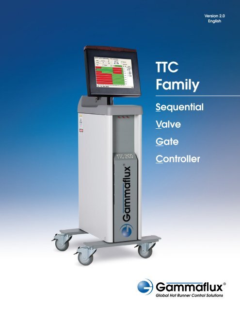
Version 2.0<br />
English<br />
TTC<br />
Family<br />
Sequential<br />
Valve<br />
Gate<br />
Controller
Sequential Valve Gate Control (<strong>SVGC</strong>)<br />
Precisely Control the Material Flow Front<br />
Manufacturers of large, complex or difficult to<br />
fill parts often turn to Sequential Valve Gate<br />
Control to solve molding issues. All <strong>SVGC</strong><br />
applications have hot runner manifold systems<br />
with either pneumatic or hydraulic <strong>valve</strong> <strong>gate</strong>s.<br />
Using <strong>SVGC</strong> the processor has the ability to<br />
selectively open or close each <strong>valve</strong> <strong>gate</strong><br />
individually to precisely <strong>control</strong> the material<br />
flow front. Filling the cavity in a sequence has<br />
the following potential benefits:<br />
• Knit line <strong>control</strong><br />
• Improved straightness<br />
• Lighter weight parts<br />
• Dimension improvement<br />
Diagnostics<br />
Through extensive input from processors using<br />
existing <strong>SVGC</strong> units, <strong>Gammaflux</strong> created a<br />
system that provides a clearer understanding<br />
of the sequence to ease troubleshooting. One of<br />
our graphical screens is shown below, the green<br />
potion of the bar indicates that the <strong>valve</strong> <strong>gate</strong><br />
is open, the red portion shows that the <strong>valve</strong><br />
<strong>gate</strong> is closed before starting the sequence.<br />
Speed<br />
All <strong>SVGC</strong> applications rely on speed, accuracy and repeatability to produce<br />
the best possible part shot after shot. The integrated eight (8) output version<br />
monitors each of the 7 digital and 2 analog inputs every millisecond (1 mSec.).<br />
As a result the <strong>Gammaflux</strong> <strong>SVGC</strong> module has the ability to open or close each<br />
<strong>valve</strong> <strong>gate</strong> every millisecond (1 mSec.).<br />
Hot Runner/<strong>SVGC</strong> Combination<br />
<strong>Gammaflux</strong>, long known for hot runner innovation and superior performance,<br />
can provide both hot runner <strong>control</strong> and <strong>SVGC</strong> in one enclosure with one interface<br />
and one menu for both the hot runner and sequence. The integrated <strong>sequential</strong><br />
hardware can open or close 8, 16 or 32 pneumatic or hydraulic <strong>valve</strong> <strong>gate</strong>s.<br />
Calibration<br />
Each analog input is easily calibrated on the screen for maximum resolution<br />
and accuracy. Set points can be entered in up to four (4) digits. The inputs can<br />
be calibrated to only read a very fine portion of the total range if more setpoint<br />
clarity is required.<br />
Programmable Alarms (Closed Loop Monitoring)<br />
The <strong>control</strong>ler can be programmed to alarm if the event happens too early or<br />
too late based on historical sequences. This time based alarm is selectable and<br />
can provide valuable quality <strong>control</strong> information for a historically open loop<br />
<strong>control</strong> application.<br />
System Rules<br />
Ten (10) system rules clearly define the capabilities and safety requirements<br />
demanded by the system during the sequence.<br />
1. Each output can be opened and closed 3 times during the sequence.<br />
2. The “sequence” does not start until the “Cycle Start” input is activated.<br />
This starts the timer.<br />
3. When cycle start is activated, the <strong>control</strong>ler will force all outputs closed<br />
before starting the sequence.<br />
4. During the “sequence” and after the first <strong>valve</strong> is opened at least one output<br />
must be open at all times. If a close is prevented, it is indicated by a yellow<br />
box (summary page). That opportunity to close is lost and the <strong>gate</strong> will<br />
only close if another close event is programmed and can be satisfied.<br />
5. The “sequence” is over and the timer stops timing when the last event<br />
has occurred.<br />
6. If the “sequence” does not finish (last event completed), the <strong>control</strong>ler will<br />
not restart the “sequence” or the timer with the next “Cycle Start”. To restart<br />
one of the following must occur; loss of enable or e-stop or toggle between<br />
the maintenance and sequence mode.<br />
7. The sequence of each <strong>gate</strong> is independent of the others.<br />
8. Each event in the sequence of a <strong>gate</strong> must occur before the next event is<br />
considered by the <strong>SVGC</strong>.<br />
9. The activation of the E-Stop input or the loss of the enable input causes<br />
all <strong>gate</strong>s to immediately go to the closed states and ends the cycle, regardless<br />
of sequence programming.<br />
10. Warning: At “Injection” all <strong>valve</strong> <strong>gate</strong>s can be programmed to be closed.<br />
Typically one or more outputs are opened with the first stage of the sequence.
Integrated <strong>SVGC</strong> and Hot Runner Control<br />
Configuration shown:<br />
8 output <strong>SVGC</strong><br />
22 zones of hot runner <strong>control</strong> (15 amps per zone)<br />
Configuration<br />
Integrated or Standalone <strong>SVGC</strong><br />
(8 <strong>valve</strong> <strong>gate</strong> outputs)<br />
• 5 slots on heat sink used by <strong>SVGC</strong> (16 total)<br />
• 11 slots on heat sink available for hot runner<br />
temperature <strong>control</strong><br />
• 8 <strong>valve</strong> <strong>gate</strong> outputs (24 VDC; 12.5 amps per 8 outputs)<br />
• 7 digital inputs (24 VDC) (10-32 VDC range)<br />
• 2 analog inputs (0-10 VDC) Optional 24 volt power supply<br />
(excitation voltage)<br />
• 3 connectors on rear of enclosure<br />
• Scan Rate 1 mSec (8 outputs)<br />
Integrated or Standalone <strong>SVGC</strong><br />
(16 or 32 Valve Gate Outputs)<br />
• 16 slots on heat sink (16 total)<br />
• 16 or 32 <strong>valve</strong> <strong>gate</strong> outputs (24 VDC;<br />
20.8 amps per 16 outputs)<br />
• 11 digital inputs (24 VDC) (10-32 VDC range)<br />
• 10 analog inputs (0-10 VDC)<br />
• 3 connectors (typical) on rear of enclosure (16 outputs)<br />
• 5 connectors (typical) on rear of enclosure (32 outputs)<br />
• Scan Rate 2 mSec (16 outputs)<br />
• Scan Rate 2.5 mSec (32 outputs)<br />
Stand Alone <strong>SVGC</strong><br />
Configurations shown:<br />
32 output <strong>SVGC</strong><br />
8 output <strong>SVGC</strong><br />
Customer Input Requirements<br />
• Provide 24 VDC enable signal from machine<br />
• Provide 24 VDC cycle start signal from machine<br />
• Provide Linear Position Transducer (LPT) analog signal to the<br />
<strong>Gammaflux</strong> <strong>control</strong>ler (optional)<br />
Valve Gate Actuation<br />
• <strong>Gammaflux</strong> provides 24 volts DC to open the <strong>valve</strong> <strong>gate</strong><br />
• <strong>Gammaflux</strong> provides 0 volts DC to close the <strong>valve</strong> <strong>gate</strong><br />
• Customer provides pneumatic or hydraulic <strong>valve</strong> <strong>gate</strong><br />
actuation system<br />
• Optional dual solenoid output<br />
• Optional 6 <strong>valve</strong> <strong>gate</strong> open/close per output<br />
Failsafe Design<br />
If the touch screen computer interface is lost (fails), both the<br />
Hot Runner and <strong>SVGC</strong> will continue to operate.<br />
Integrated & Standalone System:<br />
The “Okay to Run” output will not function without the interface.<br />
Standalone <strong>SVGC</strong> System:<br />
The “Resetable” and “Non-Resetable” alarms will not function.<br />
All Other Functions:<br />
Will continue to operate as they would normally without the touch<br />
screen interface.
Start Up Procedure<br />
Maintenance Mode<br />
1. Connect inputs and outputs<br />
2. I/O - Setup - Edit Setup -<br />
Mark used inputs and outputs<br />
3. I/O – Calibrate Analog inputs 4. I/O – Change inputs – Open/Close <strong>valve</strong><br />
<strong>gate</strong>s (test)<br />
Sequence Mode<br />
5. Events – Edit events – Program sequence 6. Summary – Start machine – Review sequence<br />
7. Events or Tool Screens – Edit events 8. Graph – Review cycle 9. Alarms – Program timeout – Learn alarms –<br />
Enable alarms<br />
Global Headquarters<br />
* <strong>Gammaflux</strong> L. P.<br />
113 Executive Drive<br />
Sterling, VA 20166 , USA<br />
) (800) 284-4477, or<br />
) +1-(703) 471-5050<br />
7 +1-(703) 689-2131<br />
8 info@gammaflux.com<br />
www.gammaflux.com<br />
European Headquarters<br />
* <strong>Gammaflux</strong> Europe GmbH<br />
Bahnstrasse 9a<br />
D-65205 Wiesbaden-Erbenheim,<br />
Germany<br />
) +49-(0)-611-973430<br />
7 +49-(0)-611-9734325<br />
8 info@gammaflux.de<br />
www.gammaflux.de<br />
Asia-Pacific Headquarters<br />
* <strong>Gammaflux</strong> Japan<br />
Yamaguchi, Ube, Japan<br />
) 7 +81-(836) 54-4369<br />
<strong>Gammaflux</strong> Singapore<br />
) +65-901-83710<br />
7 +65-656-65249<br />
8 gammafluxjpn@gammaflux.com<br />
Your Local Representative