CE marked fire dampers - Rf-Technologies
CE marked fire dampers - Rf-Technologies
CE marked fire dampers - Rf-Technologies

Create successful ePaper yourself
Turn your PDF publications into a flip-book with our unique Google optimized e-Paper software.
FIRE<br />
DAMPERS<br />
By passing through walls designed to provide a specific degree of <strong>fire</strong>-resistance in a building, the ventilation<br />
system creates a risk of propagation of <strong>fire</strong> and smoke. Fire <strong>dampers</strong> protect a building and its occupants<br />
from this risk by restoring the <strong>fire</strong>-resistance rating of the wall that has been penetrated.<br />
RF-TECHNOLOGIES OFFERS A WIDE RANGE OF FIRE DAMPERS:<br />
• Certified for all types of walls.<br />
• Compliant with the most stringent European standards.<br />
• Easy to install and seal using standard materials.<br />
• With superior air flow characteristics.<br />
RF-TECHNOLOGIES
PRINCIPLE OF OPERATION<br />
The <strong>fire</strong> damper blade is open when the ventilation system is working.<br />
They close automatically thanks to the fusible link when the temperature in the duct exceeds a certain<br />
threshold: generally 72°C. In remote-controlled and motorised models, they can also close upon<br />
receiving a signal sent out by the <strong>fire</strong> safety system when it is activated by a smoke detector, for example.<br />
When closed, the <strong>fire</strong> damper maintains compartmentation during a guaranteed period.<br />
The ventilation system is working<br />
and the <strong>fire</strong> damper is open.<br />
A <strong>fire</strong> breaks out and the temperature<br />
reaches 72°C: the fusible link<br />
melts and the damper blade closes.<br />
The intumescent material expands to<br />
create a seal that stops flames and<br />
smoke.<br />
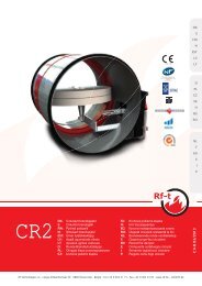
FIRE DAMPER CARTRIDGE<br />
Fire damper cartridges constitute a compact solution for small-diameter circular ducts. They are perfectly<br />
suitable for residential buildings, for example, and are noted for being easy to install. Two versions are available:<br />
the standard SC+ <strong>fire</strong> damper cartridge and the SCV+ equipped with a ventilation valve.<br />
The scope of this solution mainly depends on local regulations, because of the absence of an external<br />
resetting mechanism. A check must remain possible, and access to the fusible link must be guaranteed.<br />
The <strong>fire</strong> damper cartridge is inserted<br />
into a metal ventilation duct of the<br />
same diameter, and is held in position<br />
by its rubber seal.<br />
Both parts of the blade are held in<br />
the open position by the fusible link.<br />
When the temperature in the duct<br />
reaches 72°C, the fusible link melts,<br />
and both parts of the blade close.<br />
Two blocking hooks lock the blade in<br />
the closed position, and the intumescent<br />
material expands, providing<br />
a perfect seal to stop flames and<br />
smoke.
<strong>CE</strong> MARKING<br />
In accordance with the European Construction Products Regulation and the EN 15650:2010 standard, <strong>CE</strong><br />
Marking has been mandatory for <strong>fire</strong> <strong>dampers</strong> since 1 September 2012. <strong>Rf</strong>-<strong>Technologies</strong> <strong>fire</strong> <strong>dampers</strong> have<br />
been tested and declared compliant with European standards, as certified by the <strong>CE</strong> Marking that all<br />
products carry since 1 February 2012.<br />
The <strong>CE</strong> Marking includes technical information in the form of values declared for <strong>fire</strong> resistance criteria,<br />
durability, and air flow performance. With the standard, these declared performance characteristics provide<br />
all the information required by players in the construction market to objectively ascertain whether a product<br />
is suitable for its intended use, in compliance with the national legislation in force.<br />
FIRE RESISTAN<strong>CE</strong><br />
Fire resistance is an indication of a construction element’s capacity to withstand exposure to <strong>fire</strong> and prevent<br />
<strong>fire</strong> propagation from one compartment to another, during a given period.<br />
The <strong>fire</strong> resistance test determines the behaviour of a <strong>fire</strong> damper subject to specified temperature and<br />
pressure conditions, likely to arise during a <strong>fire</strong>. This test determines the <strong>fire</strong> resistance performance of a<br />
combination of elements: the wall in which the opening was created, the <strong>fire</strong> damper, and the material used<br />
to seal the opening. Requirements concerning these elements must be observed in order to guarantee a<br />
<strong>fire</strong>proof installation.<br />
EXAMPLE OF A EUROPEAN CLASSIFICATION<br />
EI 120 (ve i ↔ o)S<br />
(300 Pa)<br />
E – integrity<br />
E<br />
Prevents the propagation of a <strong>fire</strong> due to<br />
the passage of flames and hot gases from the<br />
side affected by <strong>fire</strong> to the non-exposed side.<br />
I – heat insulation<br />
I<br />
The temperature increase on the nonexposed<br />
side remains below a specific value.<br />
Thus, there is no risk of materials at the unexposed<br />
side catching <strong>fire</strong>.<br />
These criteria must be satisfied during a<br />
120<br />
precise classification period of 60, 90, 120,<br />
or 240 minutes.<br />
ve or ho<br />
Ve Product suitable for vertical use (in a wall)<br />
or horizontal use (in a floor).<br />
(i→o) (o→i) (i↔o)<br />
IO<br />
The tested elements satisfy the criteria for a <strong>fire</strong><br />
originating from the inside of the compartment (i)<br />
towards the outside (o), in the other direction, or in both<br />
directions.<br />
S – smoke leakage<br />
S<br />
The passage of smoke and gases remains below<br />
specific values (at ambient temperature and throughout<br />
the test). This type of leakage could cause <strong>fire</strong> propagation<br />
through the ventilation network.<br />
Pa – pressure measured in Pascals<br />
Pa<br />
The criteria are measured by applying a differential<br />
pressure of 300 Pa through the closed <strong>fire</strong> damper.<br />
This pressure level represents a working ventilation fan.<br />
Most <strong>Rf</strong>-<strong>Technologies</strong> <strong>fire</strong> <strong>dampers</strong> are tested at a higher<br />
pressure (500 or even 1500 Pa). This means that our<br />
product range is compliant with the most stringent<br />
European and local regulations.
<strong>Rf</strong>-<strong>Technologies</strong> offers one of the widest ranges of<br />
<strong>CE</strong>-<strong>marked</strong> <strong>fire</strong> <strong>dampers</strong> currently available on the<br />
market. The table below will help you choose the<br />
best <strong>fire</strong> damper for your application.<br />
TECHNICAL SPECIFICATIONS: <strong>CE</strong> MARKED RANGE<br />
Dimensions<br />
(mm)<br />
Standards<br />
(1)<br />
Airtightness<br />
according to<br />
EN 1751<br />
Optimised<br />
(2)<br />
(1)<br />
CR60 Ø 100 → 315<br />
→ EI90S B/C ü<br />
EI 90 (ve i ↔ o)S<br />
(500 Pa)<br />
EI 90 (ve i ↔ o)S<br />
(300 Pa)<br />
CR60-1s Ø 100 → 315 → EI60S B/C ü<br />
EI 60 (ve i ↔ o)S<br />
(500 Pa)<br />
Circular<br />
<strong>fire</strong> damper<br />
CR120 Ø 100 → 315 → EI120S B/C ü<br />
EI 120 (ve i ↔ o)S<br />
(500 Pa)<br />
EI 120 (ve i ↔ o)S<br />
(300 Pa)<br />
CR2 Ø 200 → 630 → EI120S B/C (5)<br />
EI 120 (ve i ↔ o)S<br />
(500 Pa)<br />
EI 90 (ve i ↔ o)S<br />
(300 Pa)<br />
CU-LT<br />
CU-LT-1s<br />
L 200 → 800<br />
H 100 → 600<br />
L 200 → 800<br />
H 100 → 600<br />
EN15650<br />
EN1366-2<br />
EN13501-3<br />
→ EI120S B/C ü<br />
→ EI120S B/C ü<br />
EI 120 (ve i ↔ o)S<br />
(500 Pa)<br />
EI 120 (ve i ↔ o)S<br />
(300 Pa)<br />
EI 120 (ve i ↔ o)S<br />
(500 Pa)<br />
Rectangular<br />
<strong>fire</strong> damper<br />
CU2<br />
CU2/B<br />
L 200 → 1200<br />
H 200 → 800<br />
(4)<br />
→ L x H<br />
2450x1650<br />
→ EI120S B/C (5)<br />
→ EI120S<br />
B/C<br />
EI 120 (ve i ↔ o)S<br />
(500 Pa)<br />
EI 90 (ve i ↔ o)S<br />
(300 Pa)<br />
EI 120 (ve i ↔ o)S<br />
(500 Pa)<br />
CA2<br />
L 200 → 700<br />
H 200 → 700<br />
→ EI60S<br />
B/C<br />
EI 60 (ve i ↔ o)S<br />
(500 Pa)<br />
CU4<br />
L 200 → 1200<br />
H 200 → 800<br />
→ EI240S<br />
B/C<br />
EI 240 (ve i ↔ o)S<br />
(500 Pa)<br />
CU2-15<br />
L 200 → 1200<br />
H 200 → 800<br />
→ EI120S<br />
B/C<br />
EI 120 (ve i ↔ o)S<br />
(1500 Pa)<br />
Circular<br />
<strong>fire</strong> damper<br />
cartridge<br />
SC(V)+ Ø100 → 200 → EI120S<br />
EI 60/90/120<br />
(ve i ↔ o)S<br />
(300 Pa)<br />
• (1) Maximum <strong>fire</strong> resistance. For further information, consult the classification guide on our website,<br />
the declaration of performance, and the classification reports.<br />
• (2) Optimised: lightweight, very little pressure loss, easy to install.<br />
• (3) Other models are available on request (ATEX-certified servomotors for explosive atmospheres, for example).<br />
• (4) Please look at our catalogue or our website for dimensions up to 1500 x 1000 mm.<br />
• (5) Class C available for large sizes only: Ø > 315 mm or L>800 mm / H>600 mm.
(1) (1) (1)<br />
Offset<br />
Automatic<br />
(fusible link)<br />
Motor<br />
(3)<br />
Electromagnetic<br />
coil<br />
CFTH MFUS(P) BF(T) BLF(T) MANO MMAG<br />
SC<br />
Fusible<br />
link<br />
EI 90 (ho i ↔ o)S<br />
(500 Pa)<br />
EI 90 (ho i ↔ o)S<br />
(300 Pa)<br />
EI 60 (ve i ↔ o)S<br />
(500 Pa) ü(1)<br />
EI 90 (ve i ↔ o)S<br />
(300 Pa)<br />
ü ü ü<br />
EI 60 (ho i ↔ o)S<br />
(500 Pa)<br />
EI 60 (ve i ↔ o)S<br />
(500 Pa)<br />
ü ü ü<br />
EI 120 (ho i ↔ o)S<br />
(500 Pa)<br />
EI 120 (ho i ↔ o)S<br />
(300 Pa)<br />
EI 60 (ve i ↔ o)S<br />
(500 Pa)<br />
EI 120 (ve i ↔ o)S<br />
(300 Pa)<br />
ü ü ü<br />
EI 120 (ho i ↔ o)S<br />
(500 Pa)<br />
EI 60 (ve i ↔ o)S<br />
(500 Pa)<br />
EI 90 (ve i ↔ o)S<br />
(300 Pa)<br />
EI 120 (ve i ↔ o)S<br />
(500 Pa)<br />
ü ü ü ü<br />
EI 120 (ho i ↔ o)S<br />
(300 Pa)<br />
EI 90 (ve i ↔ o)S<br />
(300 Pa)<br />
EI 120 (ho i ↔ o)S<br />
(500 Pa)<br />
EI 120 (ho i ↔ o)S<br />
(300 Pa)<br />
EI 90 (ve i ↔ o)S<br />
(500 Pa) ü(1)<br />
EI 120 (ve i ↔ o)S<br />
(300 Pa)<br />
ü ü ü<br />
EI 120 (ho i ↔ o)S<br />
(500 Pa)<br />
EI 90 (ve i ↔ o)S<br />
(500 Pa)<br />
EI 120 (ve i ↔ o)S<br />
(500 Pa)<br />
ü ü ü<br />
EI 120 (ho i ↔ o)S<br />
(500 Pa)<br />
EI 90 (ho i ↔ o)S<br />
(300 Pa)<br />
EI 90 (ve i ↔ o)S<br />
(500 Pa)<br />
EI 90 (ve i ↔ o)S<br />
(300 Pa)<br />
EI 120 (ve i ↔ o)S<br />
(500 Pa)<br />
ü ü ü ü<br />
ü ü ü ü<br />
ü ü ü ü<br />
ü ü ü ü<br />
ü ü ü ü<br />
EI 60/90 (ho i ↔ o)S<br />
(300 Pa)<br />
EI 60/90 (ve i ↔ o)S<br />
(300 Pa)<br />
ü<br />
Many options are available for our <strong>fire</strong> <strong>dampers</strong>. For example, an epoxy coating is available for specialist applications<br />
(laboratories and hospitals) where extreme requirements with regard to dust or corrosion have been established.<br />
A personalised numbering system can be implemented for large-scale projects, to ensure that the elements<br />
delivered match the technical drawings. Please ask us about any special requirements, since this brochure cannot<br />
provide an exhaustive list of all possibilities.
Exceptional air flow characteristics guarantee the energy<br />
and acoustic performance of the network.<br />
Fire <strong>dampers</strong> are a component of the ventilation system. That is why they must be perfectly integrated into the<br />
HVAC environment. The air flow properties of our <strong>dampers</strong> are therefore optimised to minimise both the air<br />
leakage through the tunnel and the pressure loss caused by the presence of the blade in the ventilation duct.<br />
AIRTIGHTNESS<br />
The EN 1751 standard defines different airtightness classes for <strong>fire</strong> <strong>dampers</strong> according<br />
to the extent of leakage. To go to the higher class, a product must have less<br />
leakage by a factor of 3; the leaks in a Class C system are three times smaller than<br />
those in a Class B system. Thanks to a versatile programme, we have optimised<br />
the production process for our <strong>fire</strong> <strong>dampers</strong> in order to satisfy the most stringent<br />
requirements on the market with regard to leakage:<br />
• Product optimisation, by adding rubber seals.<br />
• Test environment: investing in ultra-sensitive calibrated equipment.<br />
• Production processes: random testing of individual <strong>dampers</strong> during production.<br />
<strong>Rf</strong>-t <strong>fire</strong> <strong>dampers</strong> currently guarantee Class B or C airtightness<br />
(C being the highest class).<br />
PRESSURE LOSS<br />
The air passing through a <strong>fire</strong> damper encounters a certain amount of resistance<br />
due to the presence of the blade, the fusible link, and possibly the mechanical<br />
transmission in the damper tunnel.<br />
The new range of <strong>Rf</strong>-<strong>Technologies</strong> <strong>fire</strong> <strong>dampers</strong> guarantees <strong>fire</strong> resistance during<br />
a period of up to 120 minutes, with blades no more than 20 mm thick for circular<br />
<strong>dampers</strong> or 25 mm thick for rectangular <strong>dampers</strong>. The fusible link is in the axis of<br />
the damper blade, and the mechanical transmission is located entirely outside the<br />
tunnel. These characteristics make this range one of the most energy-saving solutions<br />
currently available on the market.<br />
As a supplier of cutting-edge solutions for the HVAC sector, <strong>Rf</strong>-<strong>Technologies</strong> willingly<br />
provides information concerning airtightness in line with the <strong>CE</strong> Marking.<br />
The air flow characteristics of <strong>Rf</strong>-t <strong>fire</strong> <strong>dampers</strong> are therefore tested during initial<br />
testing and all subsequent production checks. This deliberate choice is an additional<br />
guarantee of the air flow properties of our products and of your HVAC networks.
A wide range of certified <strong>dampers</strong> for all types of walls.<br />
To ensure their compliance with the classification documents and to guarantee a specific <strong>fire</strong> resistance<br />
rating, <strong>fire</strong> <strong>dampers</strong> must be installed in accordance with the tested configuration. According to the type of<br />
wall, the installation and sealing procedures described in the classification report must always be observed.<br />
But <strong>fire</strong> <strong>dampers</strong> are installed on construction sites, not in a laboratory. Our R&D team knows that many<br />
participants are involved in the installation of our <strong>fire</strong> <strong>dampers</strong>: engineers, bricklayers, carpenters, plasterboard<br />
installers, electricians, etc. All these professionals have an effect on whether the installation of the<br />
products is compliant.<br />
STANDARD SEALING MATERIALS<br />
To simplify the installation of our <strong>fire</strong> <strong>dampers</strong> as much as<br />
possible whilst guaranteeing compliance with the classification<br />
document, we try to use standard construction<br />
products: mortar, plaster, rock wool, plasterboard, etc.,<br />
to seal off openings. This makes it much easier to ensure<br />
compliance with the tested situation, and thus guarantees a<br />
<strong>fire</strong>proof installation.<br />
1 PRODUCT FOR ALL TYPES OF WALLS<br />
We want to simplify the job of everyone involved in the<br />
construction chain. Engineers, installers, and distributors<br />
all benefit from our basic rule: having one product, which<br />
is tested and certified for all types of walls.<br />
BASTA SEALING<br />
CR60, CR120, CR2, CU-LT and CU2 <strong>fire</strong> <strong>dampers</strong> have<br />
been successfully tested in combination with Basta-B <strong>fire</strong><br />
resistant mineral wool panels and Basta-C endothermic<br />
coating. This solution gives you even more flexibility to<br />
seal off openings in flexible and massive walls and slabs.<br />
OFFSET-MOUNTED DAMPERS<br />
When the damper connected to the duct is not centred in<br />
the wall thickness, it loses its <strong>fire</strong>-resistant properties.<br />
The CU-LT <strong>fire</strong> damper offers 60 to 120 minutes of <strong>fire</strong><br />
resistance when mounted remote from a wall and connected<br />
to a galvanised duct wrapped with rigid panels of<br />
<strong>fire</strong> resistant mineral wool or with staff. Tests for offset<br />
circular <strong>dampers</strong> are currently in progress.<br />
DRY-MOUNTED DAMPERS<br />
We do everything we can to simplify installation, and<br />
that is why we have developed CU-LT-1s and CR60-1s<br />
<strong>fire</strong> <strong>dampers</strong>, which are surface-mounted. These <strong>dampers</strong><br />
are really easy to install in any type of wall. They are<br />
especially suitable for renovation projects and building<br />
sites where access to the damper is<br />
difficult or impossible on one side of<br />
the wall (terminal damper).<br />
• The wall type can be chosen or modified at a later stage<br />
of the design.<br />
• Installation is simplified and consistent, because the<br />
same solution can be applied to the various walls on the<br />
construction site.<br />
• Stock management is simplified for our distribution<br />
partners, which guarantees fast delivery.<br />
ALL DIMENSIONS<br />
Our circular and rectangular <strong>dampers</strong> are available in an<br />
extensive range of sizes: rectangular <strong>dampers</strong> are available<br />
up to 1500 x 1000 mm in increments of 50 mm, and a<br />
battery assembly is available for the largest ducts, up to<br />
2450 x 1650 mm. Our small circular <strong>fire</strong> <strong>dampers</strong> (100 mm<br />
diameter) and rectangular <strong>fire</strong> <strong>dampers</strong> (100 mm high)<br />
provide superior return on the construction volume.<br />
Smaller ventilation ducts also provide better<br />
long-term energy performance,<br />
because ventilation systems can be<br />
appropriately sized.<br />
RF-TECHNOLOGIES PARTICIPATES IN THE BIM<br />
APPROACH TO CONSTRUCTION PROJECTS<br />
The parametric data and models of <strong>Rf</strong>-t <strong>fire</strong> <strong>dampers</strong> are<br />
available on the MEPcontent website of Stabiplan:<br />
https://www.mepcontent.eu<br />
This information is accessible free of charge for<br />
StabiCAD, Revit, ArchiCAD and AutoCAD applications.<br />
The products can thus easily be applied to Building Information<br />
Modelling (BIM).
RF-TECHNOLOGIES OOSTERZELE<br />
RF-TECHNOLOGIES<br />
<strong>Rf</strong>-<strong>Technologies</strong> is a leading European manufacturer of specialist solutions for compartmentation<br />
and smoke evacuation. The company sells its products via a vast network of partners in<br />
more than fifteen European countries. <strong>Rf</strong>-<strong>Technologies</strong> was founded in 1985. It employs 170<br />
people on two sites; one in Belgium (where its company headquarters are located) and the<br />
other in Slovakia. Ongoing investment in research and development testifies to a desire to<br />
continually develop and improve the range of products.<br />
Ref : C-FD-EN-B-2014-03<br />
RF-TECHNOLOGIES<br />
Lange Ambachtstraat 40 • B-9860 Oosterzele<br />
T: +32 9 362 31 71 • F: +32 9 362 33 07 • E: info@rft.be