Oil Burner Manual - Beckett Corp.
Oil Burner Manual - Beckett Corp.
Oil Burner Manual - Beckett Corp.

Create successful ePaper yourself
Turn your PDF publications into a flip-book with our unique Google optimized e-Paper software.
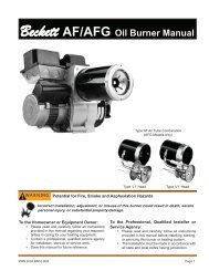
AF/AFG<br />
<strong>Oil</strong> <strong>Burner</strong> <strong>Manual</strong><br />
Potential for Fire, Smoke and Asphyxiation Hazards<br />
RESIDENTIAL BURNERS<br />
Incorrect installation, adjustment, or misuse of this burner could result in death, severe personal<br />
injury, or substantial property damage.<br />
To the Homeowner or Equipment Owner: To the Professional, Qualifi ed Installer or<br />
� Please read and carefully follow all instructions Service Agency:<br />
provided in this manual regarding your<br />
� Please read and carefully follow all instructions<br />
responsibilities in caring for your heating<br />
provided in this manual before installing,<br />
equipment.<br />
starting, or servicing this burner or heating<br />
� Contact a professional, qualifi ed service agency<br />
system.<br />
for installation, start-up or service work.<br />
� The Installation must be made in accordance<br />
� Save this manual for future reference.<br />
with all state and local codes having jurisdiction.<br />
6104BAFG R04 Page 1
Table of Contents<br />
Hazard Defi nitions and Owner’s Information ........................................................................................3<br />
Information To Be Used Only By Qualifi ed Service Technicians<br />
General Information .........................................................................................................................................4<br />
Table 1 <strong>Burner</strong> Specifi cation ................................................................................................................................4<br />
Notice Special Requirements ..............................................................................................................................5<br />
Table 2 Air Tube Combination (ATC) Codes ………………………………………………………….. .....................5<br />
Inspect/Prepare Installation Site .................................................................................................................6<br />
Inspect Chimney or Direct Vent System ..............................................................................................................6<br />
Combustion Air Supply ........................................................................................................................................7<br />
Clearances to burner and appliance ...................................................................................................................7<br />
Combustion chamber - <strong>Burner</strong> Retrofi tting ..........................................................................................................7<br />
Prepare the <strong>Burner</strong> ...........................................................................................................................................8<br />
Low Firing Rate Baffl e .........................................................................................................................................8<br />
<strong>Burner</strong> Fuel Unit ..................................................................................................................................................8<br />
Attach Air Tube ....................................................................................................................................................8<br />
Nozzle and Pump Pressure .................................................................................................................................8<br />
Install <strong>Burner</strong> Nozzle ...........................................................................................................................................8<br />
Check/Adjust Electrodes .....................................................................................................................................9<br />
Servicing nozzle line assembly ...........................................................................................................................9<br />
Check/Adjust ‘Z’ Dimension - F Heads .............................................................................................................10<br />
Check/Adjust ‘Z’ Dimension - L & V Heads ....................................................................................................... 11<br />
Mount burner on appliance ...........................................................................................................................9<br />
Mounting Options ................................................................................................................................................9<br />
Mounting Dimensions ..........................................................................................................................................9<br />
Installing the <strong>Oil</strong> Tank & Supply System ............................................................................................................12<br />
Fuel Line Valves & Filter ....................................................................................................................................12<br />
Wire <strong>Burner</strong> .......................................................................................................................................................13<br />
<strong>Burner</strong> Packaged with Appliance .......................................................................................................................13<br />
<strong>Burner</strong> Installed at Job Site ...............................................................................................................................13<br />
Special Wiring Required with Covered <strong>Burner</strong>s ................................................................................................13<br />
<strong>Burner</strong> Control .................................................................................................................................................14<br />
GeniSys Model 7505 Control ............................................................................................................................14<br />
Wiring ................................................................................................................................................................14<br />
Typical <strong>Burner</strong> Sequence of Operation for GeniSys 7505 Control ....................................................................15<br />
Typical <strong>Burner</strong> Sequence of Operation for R7184P Control ..............................................................................17<br />
Start-up <strong>Burner</strong>/Set Combustion ..............................................................................................................18<br />
Startup/checkout ...............................................................................................................................................19<br />
Set Combustion with Instruments ......................................................................................................................19<br />
Perform Regular Maintenance ...................................................................................................................20<br />
Parts Diagram ...................................................................................................................................................22<br />
<strong>Beckett</strong> Limited Warranty Information ...................................................................................................24<br />
Page 2 6104BAFG R04
Hazard Defi nitions<br />
! DANGER Indicates a hazardous situation,<br />
which, if not avoided,<br />
will result in death or serious injury.<br />
! WARNING<br />
Indicates a hazardous<br />
situation, which, if not<br />
avoided, could result in death or serious<br />
injury.<br />
! CAUTION<br />
Indicates a hazardous<br />
situation, which, if not<br />
avoided, could result in minor or moderate<br />
injury.<br />
Within the boundaries of the hazard warning, there will<br />
be information presented describing consequences if the<br />
warning is not heeded and instructions on how to avoid<br />
the hazard.<br />
NOTICE Intended to bring special attention to<br />
information, but not related to personal injury or property<br />
damage.<br />
General Information<br />
WARNING Owner’s Responsibility<br />
Incorrect installation, adjustment,<br />
and use of this burner could result in<br />
severe personal injury, death, or substantial<br />
property damage from fi re,<br />
carbon monoxide poisoning, soot or explosion.<br />
Contact a professional, qualifi ed service agency for the<br />
installation, adjustment and service of your oil heating<br />
system. This work requires technical training, trade experience,<br />
licensing or certifi cation in some states and the<br />
proper use of special combustion test instruments.<br />
Please carefully read and comply with the following<br />
instructions:<br />
� Never store or use gasoline or other fl ammable<br />
liquids or vapors near this burner or appliance.<br />
� Never attempt to burn garbage or refuse in this<br />
appliance.<br />
� Never attempt to light the burner/appliance by<br />
throwing burning material into the appliance.<br />
� Never attempt to burn any fuel not specifi ed and<br />
approved for use in this burner.<br />
� Never restrict the air inlet openings to the burner<br />
or the combustion air ventilation openings in the<br />
room.<br />
NOTICE This manual contains information that applies to both AF and AFG burners. These burners may<br />
appear to be basically identical, but there are differences in design and performance. Please review the comparison<br />
chart below:<br />
Feature AF AFG<br />
Static Pressure Capability Conventional - Low range Enhanced - Medium range<br />
Blower Wheel Design Standard strip Special tablock<br />
Inlet Airfl ow Design Standard inlet bell Special airguide<br />
UL Air Tube Combinations “F” Series ONLY “F” or “M” Series<br />
Igniter Gaskets Baseplate/Barrier Optional, as specifi ed Required, always specifi ed<br />
Low Firing Rate Baffl e Not required Required, per specifi cation<br />
Figure 1. <strong>Burner</strong> label location<br />
6104BAFG R04 Page 3<br />
!
General Information<br />
To the Owner:<br />
Thank you for purchasing a <strong>Beckett</strong> burner<br />
for use with your heating appliance. Please pay attention<br />
to the Safety Warnings contained within this<br />
instruction manual. Keep this manual for your records<br />
and provide it to your qualifi ed service agency for use<br />
in professionally setting up and maintaining your oil<br />
burner.<br />
Your <strong>Beckett</strong> burner will provide years of effi cient operation<br />
if it is professionally installed and maintained<br />
by a qualifi ed service technician. If at any time the<br />
burner does not appear to be operating properly, immediately<br />
contact your qualifi ed service agency<br />
for consultation.<br />
We recommend annual inspection/service of your<br />
oil heating system by a qualifi ed service agency.<br />
Daily – Check the room in which your burner/appliance<br />
is installed. Make sure:<br />
• Air ventilation openings are clean and unobstructed<br />
• Nothing is blocking burner inlet air openings<br />
• No combustible materials are stored near the heating<br />
appliance<br />
• There are no signs of oil or water leaking around<br />
the burner or appliance<br />
Weekly<br />
• Check your oil tank level. Always keep your oil tank<br />
full, especially during the summer, in order to prevent<br />
condensation of moisture on the inside surface<br />
of the tank.<br />
WARNING Do NOT Alter the Original<br />
!<br />
<strong>Burner</strong> Design<br />
Tampering with or altering the burner design<br />
could seriously impair performance, resulting<br />
in loss of static pressure, damage to the system<br />
components, reduced air volume, heavy smoke,<br />
fl ame impingement, appliance sooting, hot gas<br />
puff-back, and asphyxiation or fi re hazards.<br />
Maintain the design to its original confi guration.<br />
Only use parts specifi ed for AF or AFG <strong>Burner</strong>s<br />
Do NOT remove the air guide from the AFG chassis.<br />
Do NOT use ‘M’ Series air tube combinations on AF <strong>Burner</strong>s.<br />
Never try to convert an AF to an AFG or vice versa<br />
Any design alteration will:<br />
� Void UL Listing<br />
� Void manufacturer’s warranties<br />
� Seriously impact burner performance<br />
� Greatly increase your liability risk<br />
! WARNING<br />
Impaired <strong>Burner</strong> Performance<br />
and Fire Hazard.<br />
Do NOT operate the burner beyond specifi cations<br />
outlined in the following Table.<br />
� For applications beyond these limits, consult<br />
<strong>Beckett</strong> Technical Service at 1-800-645-2876.<br />
� NOTE: Some packaged appliances with burners<br />
may be agency listed as a unit to operate beyond<br />
these limits. Consult the appliance manufacturer’s<br />
specifi cations and agency approvals for<br />
verifi cation.<br />
Capacity<br />
(Note 1)<br />
Certifi cations/<br />
Approvals<br />
Table 1 – <strong>Burner</strong> Specifi cations<br />
‘F’ Head (AF & AFG)<br />
Firing rate range: ..............0.40 – 3.00 GPH<br />
Input: ....................... 56,000 – 420,000 Btu<br />
‘L1’ Head (AFG Only)<br />
Firing rate range: ..................0.40 - 1.10 GPH<br />
Input: ..................... 56,000 – 154,000 Btu/h<br />
‘L2’ Head (AFG Only)<br />
Firing rate range: .................0.50 - 1.00 GPH<br />
Input: ...................... 70,000 – 140,000 Btu/h<br />
‘V1’ Head (AFG Only)<br />
Firing rate range: .................0.75 - 2.75 GPH<br />
Input: .................... 105,000 – 385,000 Btu/h<br />
UL listed to comply with ANSI/UL296 and CSA-B140.0<br />
Fuels U. S No. 1 or No. 2 heating oil only (ASTM D396)<br />
Canada No. 1 stove oil or No. 2 furnace oil only<br />
Electrical Power supply:............ 120 volts AC, 60 Hz single phase<br />
Operating load: .......... Amps max<br />
Motor: .........................1/7 hp, 3450 rpm, NEMA 48M frame<br />
PSC rotation CCW when facing<br />
shaft end<br />
Ignition: ......................Continuous duty solid-state igniter<br />
Fuel pump Outlet pressure: ..................................Note 2<br />
Air tube ATC code: ...................................See Table 2<br />
Dimensions<br />
(with cover)<br />
Ambient<br />
Operating<br />
Temperature<br />
! CAUTION<br />
DO NOT USE GASOLINE, CRANKCASE OIL,<br />
OR ANY OIL CONTAINING GASOLINE.<br />
Height (maximum) ....................... 12.5 inches<br />
Width (maximum) .......................... 15 inches<br />
Depth ......................................... 9.25 inches<br />
Air tube diameter ....................... 4.00 inches<br />
+32o F. (0 C.) Minimum<br />
+115o F. (+46 C.) Maximum<br />
(See above Warning)<br />
Moisture 5% to 95% RH, non-condensing and non-crystallizing<br />
Note 1: Approval agency listed rating for these burners is 0.40 to 3.00<br />
gph. However, the fi ring rate range is limited by the specifi c<br />
air tube combination being used. Refer to Table 2.<br />
Note 2. See appliance manufacturer’s burner specifi cations for recommended<br />
pump discharge pressure.<br />
Page 4 6104BAFG R04
Table 2 – Air Tube Combination (ATC) codes<br />
Firing<br />
Rate<br />
(gph)<br />
(minmax)<br />
Head Static<br />
plate<br />
size<br />
Venturi<br />
Notice Special Requirements<br />
� THE INSTALLATION OF A BURNER SHALL BE<br />
IN ACCORDANCE WITH THE REGULATIONS<br />
OF AUTHORITIES HAVING JURISDICTION.<br />
� For recommended installation practices in the<br />
U.S. refer to the latest edition of NFPA 31. (CSA-<br />
B139 and CSA-B140 in Canada.<br />
� Concealed damage — If you discover damage to<br />
the burner or controls during unpacking, notify the<br />
carrier at once and fi le the appropriate claim.<br />
� When contacting <strong>Beckett</strong> for service information<br />
— Please record the burner serial number (and<br />
have available when calling or writing). You will<br />
fi nd the serial number on the silver label located<br />
on the left rear of the burner. Refer to Figure 1.<br />
ATC Codes for usable air tube lengths<br />
(‘A’ in inches; See Figure 3.)<br />
General Specifi cations<br />
(inches) 4-1/2 5 5-3/8 6-5/8 7 7-1/4 9 10-1/2 13 16<br />
0.50-0.75 F0 3-3/8U None AF44XR - AF53XR AF65XR - AF72XR AF90XR AF104XR AF130XR A160XR<br />
0.75-1.25 F3 2-3/4U None AF44XN - AF53XN AF65XN - AF72XN AF90XN AF104XN AF130XN AF160XN<br />
0.85-1.35 F4 2-3/4U None AF44WH - AF53WH AF65WH - AF72WH AF90WH AF104WH AF130WH AF160WH<br />
0.85-1.65 F6 2-3/4U None AF44YB - AF53YB AF65YB - AF72YB AF90YB AF104YB AF130YB AF160YB<br />
1.10-2.00 F12 2-3/4U None AF44XO - AF53XO AF65XO - AF72XO AF90XO AF104XO AF130XO AF160XO<br />
1.65-2.50 F22 2-3/4U None AF44XP - AF53XP AF56XP - AF72XP AF90XP AF104XP AF130XP AF160XP<br />
2.50-3.00 F31 None None AF44XS - AF53XS AF65XS - AF72XS AF90XS AF104XS AF130XS AF160XS<br />
0.50-1.10 L1 3-3/8U 8hole - AFG50MB - - AFG70MB - AFG90MB - - -<br />
0.50-1.00 L2 2-3/4U 8hole AFG50MP - - AFG70MP - AFG90MP - - -<br />
0.75-2.75 V1 2-3/4U 8hole - AFG50MD - - AFG70MD - AFG90MD - - -<br />
0.40-0.75 F0 3-1/2U None AF44WG - AF53WG AF65WG - AF72WG AF90WG AF104WG AF130WG A160WG<br />
WARNING Professional Service<br />
!<br />
Required<br />
Incorrect installation, adjustment,<br />
and use of this burner could result<br />
in severe personal injury, death, or<br />
substantial property damage from<br />
fi re, carbon monoxide poisoning, soot or explosion.<br />
Please read and understand the manual supplied with<br />
this equipment. This equipment must be installed, adjusted<br />
and put into operation only by a qualifi ed individual<br />
or service agency that is:<br />
� Licensed or certifi ed to install and provide technical<br />
service to oil heating systems.<br />
� Experienced with all applicable codes, standards<br />
and ordinances.<br />
� Responsible for the correct installation and commission<br />
of this equipment.<br />
� Skilled in the adjustment of oil burners using<br />
combustion test instruments.<br />
The installation must strictly comply with all applicable<br />
codes, authorities having jurisdiction and the latest revision<br />
of the National Fire Protection Association Standard<br />
for the installation of <strong>Oil</strong>-burning Equipment, NFPA 31<br />
(or CSA-B139 and CSA-B140 in Canada).<br />
Regulation by these authorities take precedence over<br />
the general instructions provided in this installation<br />
6104BAFG R04 Page 5
Inspect/Prepare Installation Site<br />
!<br />
Inspect Chimney or Direct Vent System<br />
1.<br />
2.<br />
3.<br />
4.<br />
WARNING<br />
�<br />
�<br />
�<br />
�<br />
�<br />
Fire, Smoke & Asphyxiation<br />
Hazard<br />
Carefully inspect the chimney or exhaust vent<br />
system.<br />
Make sure it is properly sized and in good working<br />
condition.<br />
Follow the instructions supplied by the appliance<br />
manufacturer.<br />
The installation must strictly comply with all applicable<br />
codes, authorities having jurisdiction and<br />
the latest revision of the National Fire Protection<br />
Association Standard NFPA 31 for the installation<br />
of chimneys and vent sizing, (or CSA-B139<br />
and CSA-B140 in Canada).<br />
Regulation by these authorities take precedence<br />
over the general instructions provided in this installation<br />
manual.<br />
Starting with minimum gph fi ring rate, the minimum<br />
size recommended is 6” fl ue pipe with 8” X<br />
8” inside chimney, unless specifi ed otherwise by<br />
the appliance manufacturer.<br />
A chimney fl ue shall extend at least 3 feet above<br />
the highest point at which the chimney comes<br />
in contact with the roof, and not less than 2 feet<br />
above the highest roof surface or structure within<br />
10 feet horizontally of the chimney. Refer to Figure<br />
2.<br />
Any accumulation of soot or debris in chimney<br />
offsets should be removed<br />
Any obstructions such as a protruding joint or a<br />
piece of broken tile wedged in the chimney should<br />
be removed.<br />
Figure 2 – Chimney Design - Above the Roof<br />
No other appliance connection should be made to<br />
the same fl ue pipe.<br />
The fl ue pipe should have an upward pitch toward<br />
the chimney of at least 1/4” per foot of length. It<br />
should fi t tightly and should not project into the<br />
chimney.<br />
Any leakage between tiles, around clean-out<br />
doors, or around the vent pipe should be sealed.<br />
INSULATED STAINLESS STEEL CHIMNEY LINERS<br />
The new designs of high effi ciency oil furnaces<br />
and boilers in conjunction with fl ame retention oil<br />
burners are more effi cient. One result of increased<br />
effi ciency is lower fl ue gas temperatures. As<br />
fl ue gases rise in the chimney, they will cool and<br />
condense when they reach the dew point. The<br />
condensation will mix with the sulphur in the fl ue<br />
gases creating sulphuric acid. The acid will attack<br />
the chimney mortar, brick and clay liners causing<br />
corrosion, deterioration and blockage of the<br />
chimney. Eventually the blockage could prevent<br />
exhausting the fl ue gases. Instead, the fl ue gases<br />
could vent out the barometric damper into the living<br />
space.<br />
Therefore, it is strongly recommended that an approved<br />
insulated stainless steel liner be installed.<br />
For those installations not requiring a chimney,<br />
such as through-the-wall vented appliances, follow<br />
the instructions given by the appliance and<br />
power venter (if used) manufacturers.<br />
Page 6 6104BAFG R04<br />
5.<br />
6.<br />
7.<br />
�<br />
NOTE: Correct<br />
chimney design is<br />
shown by dotted<br />
lines. Incorrect<br />
chimney design,<br />
as shown by the<br />
solid lines, may<br />
result in downdrafts.
Combustion air supply<br />
Adequate Combustion<br />
WARNING<br />
!<br />
and Ventilation Air Supply<br />
Required<br />
Failure to provide adequate air supply could<br />
seriously affect the burner performance and result<br />
in damage to the equipment, asphyxiation,<br />
explosion or fi re hazards.<br />
�<br />
�<br />
The burner cannot properly burn the fuel if it is not<br />
supplied with a reliable combustion air source.<br />
Follow the guidelines in the latest editions of the<br />
NFPA 31 and CSA-B139 regarding providing adequate<br />
air for combustion and ventilation.<br />
Appliance located in confi ned space<br />
The confi ned space should have two (2) permanent<br />
openings: one near the top of the enclosure and<br />
one near the bottom of the enclosure. Each opening<br />
shall have a free area of not less than (1) one<br />
square inch per 1,000 BTU’s per hour of the total<br />
input rating of all appliances within the enclosure.<br />
The openings shall have free access to the building<br />
interior, which should have adequate infi ltration<br />
from the outside.<br />
Exhaust fans and other air-using devices<br />
Size air openings large enough to allow for all airusing<br />
devices in addition to the minimum area required<br />
for combustion air. If there is any possibility<br />
of the equipment room developing negative pressure<br />
(because of exhaust fans or clothes dryers, for<br />
example), either pipe combustion air directly to the<br />
burner or provide a sealed enclosure for the burner<br />
and supply it with its own combustion air supply.<br />
Direct air supply and sidewall venting<br />
� Some AFG burners are equipped with combustion<br />
air boots to allow use of outside air for combustion.<br />
� When sidewall venting appliances, carefully follow<br />
appliance and power venter instructions for<br />
installation and wiring.<br />
WARNING Follow the Outside Air Kit<br />
!<br />
Instructions Exactly<br />
Failure to comply could result in impaired combustion,<br />
appliance soot-up, puffback of smoke,<br />
and fi re or asphyxiation hazards.<br />
� Do not attempt to install outside air piping to<br />
the burner without using the outside air kit and<br />
instructions.<br />
Inspect/Prepare Installation Site<br />
Outside air kit applications<br />
Refer to separate instruction sheet supplied with<br />
AF/AFG outside air kit for installation. This optional<br />
kit allows combustion air to be piped directly to the<br />
burner (<strong>Beckett</strong> part number 51747).<br />
Clearances to burner and appliance<br />
� Provide space around burner and appliance for<br />
easy service and maintenance.<br />
� Check minimum clearances against those shown<br />
by the appliance manufacturer and by applicable<br />
building codes.<br />
WARNING Protect Steel Combustion<br />
!<br />
Chamber From Burnout<br />
Failure to comply could result in damage to the<br />
heating equipment and result in fi re or asphyxiation<br />
hazards.<br />
� When retrofi tting appliances that have unlined<br />
stainless steel combustion chambers, protect<br />
the chamber by lining the inside surfaces with a<br />
ceramic fi ber blanket, such as a wet-pac or other<br />
suitable refractory material.<br />
� Some steel chambers may not require liners<br />
because the appliance was designed and tested<br />
for use with fl ame retention burners. Refer to the<br />
manufacturer’s instructions.<br />
Combustion chamber — <strong>Burner</strong> retrofi tting<br />
Verify that the appliance combustion chamber provides<br />
at least the minimum dimensions given in<br />
Table 3.<br />
Table 3. Chamber Dimensions<br />
Firing Rate<br />
(GPH)<br />
Chamber Dimensions (inches)<br />
6104BAFG R04 Page 7<br />
Round<br />
I.D.<br />
Rectangular Height Floor to<br />
nozzle<br />
Width Length<br />
0.50 8 7 8 12 5-6<br />
0.75 9 8 9 12 5-6<br />
1.00 10 9 10 12.5 5-6<br />
1.25 11 10 11 12.5 5-6<br />
1.50 12 11 12 13 6-7<br />
2.00 14 12 15 13.5 6-7<br />
2.50 16 13 17 14 7-8<br />
3.00 18 14 18 15 7-8
Inspect/Prepare Installation Site<br />
Prepare the <strong>Burner</strong><br />
Low Firing Rate Baffl e<br />
The AFG Low Firing Rate Baffl e (LFRB) reduces<br />
the air fl ow and pressure. The LFRB is sometimes<br />
used for fi ring rates under 1.00 gph as listed in<br />
Table 4. Refer to the appliance manufacturer’s instructions.<br />
Do not omit the LFRB when specifi ed.<br />
Omitting the baffl e when specifi ed or installing the<br />
baffl e when not specifi ed could result in impaired<br />
burner performance.<br />
<strong>Burner</strong> fuel unit<br />
� Verify that the burner fuel unit is compatible with<br />
the oil supply system. For more details, refer to<br />
the pump manufacturer’s instructions provided<br />
with the burner.<br />
Attach air tube (if not already installed)<br />
If using a fl ange and gasket, slide them onto the air<br />
tube. Then attach the air tube to the burner chassis<br />
using the four sheet metal screws provided. Refer<br />
to Figure 4 for details.<br />
Nozzle and Pump Pressure<br />
WARNING Correct Nozzle and Flow<br />
!<br />
Rate Required<br />
Incorrect nozzles and fl ow rates<br />
could result in impaired combustion,<br />
under-fi ring, over-fi ring, sooting,<br />
puff-back of hot gases, smoke<br />
and potential fi re or asphyxiation hazards.<br />
Use only nozzles having the brand, fl ow rate (gph), spray<br />
angle and pattern specifi ed by the appliance manufacturer.<br />
Follow the appliance manufacturer’s specifi cations for<br />
the required pump outlet pressure for the nozzle, since<br />
this affects the fl ow rate.<br />
� Nozzle manufacturers calibrate nozzle fl ow rates<br />
at 100 psig.<br />
� When pump pressures are higher than 100 psig,<br />
the actual nozzle fl ow rate will be greater than<br />
the gph stamped on the nozzle body. (Example:<br />
A 1.00 gph nozzle at 140 psig = 1.18 gph)<br />
Securely tighten the nozzle (90 torque inch pounds). For<br />
typical nozzle fl ow rates at various pressures refer to<br />
Table 5.<br />
Table 4. AFG Reduced Firing Rates (with<br />
LFRB)<br />
<strong>Burner</strong> head type Low Firing Rate Baffl e installed<br />
F0 up to 0.65 gph<br />
F3 or L1 up to 0.85 gph<br />
F4 or F6 up to 0.90 gph<br />
V1 up to 1.00 gph<br />
Table 5. Nozzle Flow Rate by Size<br />
Nozzle fl ow rate U. S. gallons per hour of No. 2 fuel oil when<br />
pump pressure (psig) is:<br />
Nozzle<br />
size<br />
(rated at<br />
100 psig)<br />
Install burner nozzle (if not already installed)<br />
1. Remove the plastic plug protecting the nozzle<br />
adapter threads<br />
2. Place a 3/4” open-end wrench on the nozzle<br />
adapter. Insert the nozzle into the adapter and fi nger<br />
tighten. Finish tightening with a 5/8” open-end<br />
wrench. Use care to avoid bending the burner head<br />
support legs or electrodes. If you remove the head<br />
to replace the nozzle (type “L1”/“L2” or “V1” heads),<br />
carefully reconnect the head to the nozzle adapter,<br />
making sure that the head support makes contact<br />
with the nozzle adapter shoulder. Refer to Figure<br />
5 or 6.<br />
Page 8 6104BAFG R04<br />
125<br />
psi<br />
140 psi 150 psi 175 psi 200 psi<br />
0.40 0.45 0.47 0.49 0.53 0.56<br />
0.50 0.56 0.59 0.61 0.66 0.71<br />
0.60 0.67 0.71 0.74 0.79 0.85<br />
0.65 0.73 0.77 0.80 0.86 0.92<br />
0.75 0.84 0.89 0.92 0.99 1.06<br />
0.85 0.95 1.01 1.04 1.13 1.20<br />
0.90 1.01 1.07 1.10 1.19 1.27<br />
1.00 1.12 1.18 1.23 1.32 1.41<br />
1.10 1.23 1.30 1.35 1.46 1.56<br />
1.20 1.34 1.42 1.47 1.59 1.70<br />
1.25 1.39 1.48 1.53 1.65 1.77<br />
1.35 1.51 1.60 1.65 1.79 1.91<br />
1.50 1.68 1.77 1.84 1.98 2.12<br />
1.65 1.84 1.95 2.02 2.18 2.33<br />
1.75 1.96 2.07 2.14 2.32 2.48<br />
2.00 2.24 2.37 2.45 2.65 2.83<br />
2.25 2.52 2.66 2.76 2.98 -<br />
2.50 2.80 2.96 - - -
3. If the nozzle is already installed, remove the nozzle<br />
line assembly to verify that the nozzle size and<br />
spray pattern are correct for the application (per appliance<br />
manufacturer’s information). Verify that the<br />
electrode tip settings comply with Figure 3.<br />
4. If the nozzle is not installed, obtain a nozzle from<br />
the manufacturer, having the capacity and spray<br />
angle specifi ed in the appliance manufacturer’s information.<br />
For conversions or upgrades, when information<br />
is not available for the application:<br />
� Refer to Table 6 to select the mid-range nozzle<br />
spray angle for the head type being used.<br />
� Fire the burner and make sure the combustion<br />
is acceptable and the fl ame is not impinging on<br />
chamber surfaces.<br />
� If a shorter fl ame is needed, select a wider spray<br />
angle. If a longer fl ame is needed, select a narrower<br />
spray angle.<br />
� Either hollow or solid spray patterns may be used.<br />
If combustion results are not satisfactory with the<br />
selected spray pattern, try the other pattern.<br />
Table 6. Nozzle Spray Angles<br />
Recommended nozzle spray angles<br />
“F” head 70° or 80° nozzle<br />
“L1” & “L2” head 45°, 60°, or 70° nozzle<br />
“V1” head 45°, 60°, or 70° nozzle<br />
Check/adjust electrodes<br />
Check the electrode tip settings. Adjust if necessary<br />
to comply with the dimensions shown in Figure<br />
3. To adjust, loosen the electrode clamp screw<br />
and slide/rotate electrodes as necessary. Securely<br />
tighten the clamp screw when fi nished.<br />
Prepare the <strong>Burner</strong><br />
Figure 3. – Electrode Tip Adjustment<br />
Standard Dimensions for F, L1, and V1 Heads.<br />
The Dimensions shown below are for use with L2 heads<br />
and M series air tube combinations ending with an ‘N’ suffi<br />
x (example: AFG70MDAQN)<br />
Mount burner on appliance<br />
Mounting options<br />
1. Bolt the burner to the appliance using the factory-mounted<br />
fl ange or an adjustable fl ange.<br />
Servicing nozzle line assembly<br />
1. Turn off power to burner before proceeding.<br />
2. Disconnect oil connector tube from nozzle line.<br />
3. Loosen the two screws securing igniter retaining<br />
clips and rotate both clips to release igniter<br />
baseplate. Then tilt igniter back on its hinge.<br />
4. Remove splined nut.<br />
5. “F” head air tube. - Remove nozzle line assembly<br />
from burner, being careful not to<br />
damage the electrodes or insulators while<br />
handling. To ease removal of long assemblies<br />
(over 9 inches), rotate assembly 180° from<br />
installed position after pulling partially out of<br />
tube.<br />
6. “L1”, “L2”, and “V1” head air tubes. - Slide<br />
nozzle line assembly forward (further into air<br />
tube) so the head clears the venturi opening.<br />
Then rotate the nozzle line assembly 90° so<br />
the nozzle line end points up. Pull the nozzle<br />
line assembly toward you and remove assembly<br />
from burner.<br />
Mounting dimensions<br />
1. When using the <strong>Beckett</strong> universal adjustable<br />
fl ange, mount the air tube at a 2° downward<br />
pitch unless otherwise specifi ed by the appliance<br />
manufacturer.<br />
2. Verify that the air tube installed on the burner<br />
provides the correct insertion depth. See Figure<br />
7.<br />
3. The end of the air tube should normally be ¼”<br />
back from the inside wall of the combustion<br />
chamber. Never allow the leading edge of the<br />
head assembly to extend into the chamber, unless<br />
otherwise specifi ed by the heating appliance<br />
manufacturer. Carefully measure the insertion<br />
depth when using an adjustable fl ange.<br />
Verify the insertion depth when using a welded<br />
fl ange.<br />
7. To replace the nozzle assembly, reverse the<br />
above steps.<br />
6104BAFG R04 Page 9
Prepare the <strong>Burner</strong><br />
Figure 4. Check/Adjust ‘Z’ Dimension for ‘F’ Heads<br />
1-3/8”<br />
1-1/8”<br />
WARNING Adjust the ‘Z’ dimen-<br />
!<br />
sion to the required<br />
specifi cation.<br />
Incorrect Adjustments could cause combustion<br />
problems, carbon deposition from fl ame<br />
impingement, heavy smoke generation and<br />
fi re hazard.<br />
� Make all adjustments exactly as outlined in<br />
the following information.<br />
Check/Adjust ‘Z’ Dimension - ‘F’ heads<br />
1. The important ‘Z’ dimension is the distance from the face of the nozzle<br />
to the fl at face of the head (or heat shield, if applicable). This distance<br />
for F heads is 1-⅛” (1-⅜” if the air tube has a heat shield). The<br />
“Z” dimension is factory set for burners shipped with the air tube installed.<br />
Even if factory set, verify that the “Z” dimension has not been<br />
changed.<br />
2. Use the following procedure to adjust the “Z” dimension, if it is not<br />
�<br />
�<br />
�<br />
�<br />
�<br />
�<br />
correct:<br />
Turn off power to the burner.<br />
Disconnect the oil connector tube from the nozzle line<br />
See above fi gure. Loosen the splined nut from the nozzle line.<br />
Loosen the hex head screw securing the escutcheon plate to the<br />
burner housing.<br />
Place the end of a ruler at the face of the nozzle and, using a<br />
straight edge across the head, measure the distance to the face of<br />
the head. A <strong>Beckett</strong> T501 gauge may also be used.<br />
Slide the nozzle line forward or back until this dimension for F<br />
heads is 1-⅛” (1-⅜” to the face of the heat shield, if applicable).<br />
Tighten the hex head screw to secure the escutcheon plate to the<br />
burner chassis. Then tighten the splined nut and attach the oil connector<br />
tube.<br />
3. Recheck the “Z” dimension periodically when servicing to ensure the<br />
escutcheon plate has not been moved. You will need to reset the “Z”<br />
dimension if you replace the air tube or nozzle line assembly. The<br />
<strong>Beckett</strong> Z gauge (part number Z-2000) is available to permit checking<br />
the F head “Z” dimension without removing the burner from the appliance.<br />
<strong>Burner</strong> Dimensions<br />
Dimension (inches) F Head L1<br />
Head<br />
For usable length A (inches)<br />
Page 10 6104BAFG R04<br />
L2<br />
Head<br />
V1<br />
Head<br />
H (nozzle to head), +1/32 N/A 1/4 7/32 1/4<br />
L (Total tube length) A+1/2 A+1/2 A+1/2 A+1/2<br />
R (electrode length), + 1/4 A+2-1/4 A+1-1/8 A+1-1/8 A+1-1/8<br />
S (adapter to static plate), +<br />
1/16<br />
(Note 1) 1-3/8 1-3/8 1-3/8<br />
Q (nozzle line length), A+ 15/16 A+ 3/16 A+ 3/16 A+ 3/16<br />
Z (F head-no heat shield) 1-1/8 N/A N/A N/A<br />
(F head-with heat shield) 1-3/8 N/A N/A N/A<br />
Z (L1 head w/straight<br />
N/A 1-3/8 N/A N/A<br />
shroud) (L1/L2/V1 head<br />
w/conic shroud)<br />
N/A 1-3/4 1-3/4 1-3/4<br />
Note 1: 1-3/8 for dimension A less than 4”; 1-5/8 for dimension A from 4”<br />
through 4-1/2 “, 2-13/32 for dimension A greater than 4-1/2”.
Figure 5. Check/Adjust ‘Z’ Dimension - L1 &<br />
L2 Heads<br />
L1/L2 heads (see Table 7 and Figure 3 for dimensions)<br />
1. See fi gure above. The important “Z” dimension is the distance from<br />
the leading edge of the head to the end of the air tube. This distance<br />
for L1 & L2 heads is 1-⅜” if the tube has a straight shroud or 1-¾” if<br />
the air tube has a conic shroud. The “Z” dimension is factory set for<br />
Figure 6. Check/Adjust ‘Z’ Dimension - V1<br />
Heads<br />
V1 heads (see Table below and Figure above for dimensions)<br />
1. See fi gure above. The important “Z” dimension is the distance from<br />
the leading edge of the head to the end of the air tube. This distance<br />
for V1 heads is 1-¾”. The “Z” dimension is factory set for burners<br />
shipped with the air tube installed. Even if factory set, verify that the<br />
“Z” dimension has not been changed.<br />
Set head position adjusting plate (V1 head only)<br />
1. After setting “Z” dimension, loosen head adjusting plate hex head<br />
screw and nozzle line splined nut. Move the nozzle line assembly until<br />
the burner reference indicator lines up with the head adjusting plate<br />
setting number given in Table shown below.<br />
2. Tighten the hex head screw and splined nut. (DO NOT loosen the<br />
acorn nut when setting head position.) Refer to the manufacturer’s instructions<br />
for OEM settings.<br />
3. The position of the head affects air fl ow volume and pattern. For most<br />
applications, the burner will perform satisfactorily with the air adjustment<br />
plate setting of Table shown below.<br />
4. If combustion results indicate the need for change, adjust the head position<br />
adjusting plate forward or back one position at a time to optimize<br />
combustion.<br />
burners shipped with the air tube installed. Even if factory set, verify<br />
that the “Z” dimension has not been changed.<br />
2. Use the following procedure to adjust the “Z” dimension, if it is not<br />
correct:<br />
Turn off power to the burner.<br />
Disconnect the oil connector tube from the nozzle line.<br />
Refer to fi gure. Loosen the splined nut from the nozzle line.<br />
Loosen the hex head screw securing the escutcheon plate to the<br />
burner housing.<br />
Place the end of a ruler at the leading edge of the head and, using<br />
a straight edge across the end of the air tube, measure the<br />
distance to the end of the tube. A <strong>Beckett</strong> T501 gauge may also<br />
be used.<br />
Slide the nozzle line forward or back until this dimension is 1-⅜”<br />
for L1 & L2 heads if the tube has a straight shroud, or 1-¾” if the<br />
air tube has a conic shroud.<br />
Tighten the hex head screw to secure the escutcheon plate to<br />
the burner chassis. Then tighten the splined nut and attach the<br />
oil connector tube.<br />
3. Recheck the “Z” dimension periodically when servicing to ensure<br />
the escutcheon plate has not been moved. You will need to reset<br />
the “Z” dimension if you replace the air tube or nozzle line assembly.<br />
Table for initial adjusting plate settings for V1<br />
Head<br />
V1 Adjusting<br />
Plate Setting<br />
AFG with V1<br />
Head<br />
<strong>Burner</strong> Firing<br />
Rates<br />
0 0.75-1.00<br />
1 1.00-1.50<br />
2 1.50-1.75<br />
3 1.75-2.00<br />
4 2.00-2.25<br />
5 2.25-2.50<br />
6 2.50-2.75<br />
6104BAFG R04 Page 11<br />
�<br />
�<br />
�<br />
�<br />
�<br />
�<br />
2. Use the following procedure to adjust the “Z” dimension, if it is not<br />
�<br />
�<br />
�<br />
�<br />
�<br />
�<br />
Prepare the <strong>Burner</strong><br />
correct:<br />
Turn off power to the burner.<br />
Disconnect the oil connector tube from the nozzle line.<br />
See fi gure above. Loosen the splined nut from the nozzle line.<br />
Loosen the hex head screw securing the head adjusting plate to<br />
the burner housing.<br />
Loosen the acorn nut. Move the head adjusting plate until the “0”<br />
lines up with the reference indicator on the housing, and retighten<br />
the hex head screw. Place the end of a ruler at the leading edge of<br />
the head and, using a straight edge across the end of the air tube,<br />
measure the distance to the end of the tube. A <strong>Beckett</strong> T501 gauge<br />
may also be used.<br />
Slide the nozzle line forward or back until this dimension is 1-¾” for<br />
V1 heads. Tighten the acorn nut.<br />
Tighten the hex head screw to secure the head adjusting plate to<br />
the burner chassis. Then tighten the splined nut and attach the oil<br />
connector tube.<br />
3. Recheck the “Z” dimension periodically when servicing to ensure the<br />
escutcheon plate has not been moved. You will need to reset the “Z”<br />
dimension if you replace the air tube or nozzle line assembly.
Mount burner on appliance<br />
Figure 7. – Mounting <strong>Burner</strong> in Appliance<br />
If space between burner<br />
air tube and opening<br />
exceeds 1/2 inch, pack<br />
burner opening with ceramic<br />
fiber refractory.<br />
!<br />
Tilt down 2 o<br />
SK8745<br />
Installing the <strong>Oil</strong> Tank and Supply System<br />
Damage to the pump could cause impaired<br />
burner operation, oil leakage and appliance<br />
soot-up.<br />
WARNING<br />
! CAUTION<br />
�<br />
�<br />
�<br />
<strong>Oil</strong> Leak and Fire Hazard<br />
Install the oil tank following applicable standards<br />
in the U.S. by referring to the latest<br />
edition of NFPA 31 or CSA-B139 & CSA-B140<br />
in Canada, and all authorities having jurisdiction.<br />
Do Not Use Tefl on Tape<br />
Never use Tefl on tape on fuel oil fi ttings.<br />
Tape fragments can lodge in fuel line components<br />
and fuel unit, damaging the equipment<br />
and preventing proper operation.<br />
Use oil-resistant pipe sealant compounds.<br />
Note: to determine the proper fuel line size, refer<br />
to the fuel pump manufacturer’s instructions provided<br />
with the burner. Refer to Figure 8 or Figure 9<br />
for typical installation layouts.<br />
Fuel Line Valves and Filter<br />
Install two high quality, oil duty rated, fusible<br />
handle design shutoff valves in accessible locations<br />
on the oil supply line. Locate one close to the<br />
tank and the other close to the burner, upstream of<br />
the fi lter for service access.<br />
Install a generous capacity fi lter inside the building<br />
between the fuel tank shutoff valve and the burner,<br />
locating both the fi lter and the valve close to the<br />
burner for ease of servicing. Filter should be rated<br />
for 50 microns or less.<br />
Figure 8. – Inside Tank Gravity Feed System<br />
Figure 9. – Outside Buried Tank-Lift System<br />
NOTICE To further protect the fuel supply system<br />
and reduce nozzle orifi ce plugging with fi ring rates<br />
below 0.75 gph, a dual fi ltration system can be installed.<br />
This typically consists of a 50 micron primary fi lter,<br />
located near the fuel tank and a secondary fi lter rated for<br />
at least 10 microns located near the burner.<br />
Fuel supply level with or above burner –<br />
Do Not Install By-pass Plug<br />
WARNING<br />
!<br />
with 1-Pipe System<br />
Failure to comply could cause Immediate pump<br />
seal failure, pressurized oil leakage and the<br />
potential for a fi re and injury hazard.<br />
The burner is shipped without the by-pass plug<br />
installed.<br />
Install the by-pass plug in two-pipe oil supply<br />
systems ONLY.<br />
Page 12 6104BAFG R04<br />
�<br />
�
<strong>Oil</strong> Supply Pressure<br />
! Control Required<br />
Damage to the fi lter or pump seals could cause<br />
oil leakage and a fi re hazard.<br />
� The oil supply inlet pressure to the burner cannot<br />
exceed 3 psig.<br />
� Insure that a pressure limiting device is installed<br />
in accordance with the latest edition of NFPA 31.<br />
� Do NOT install valves in the return line.<br />
(NFPA 31, Chapter 8.)<br />
� Gravity Feed Systems: Always install an antisiphon<br />
valve in the oil supply line or a solenoid<br />
valve (RWB Part # 2182602U) in the pump/nozzle<br />
discharge tubing to provide backup oil fl ow<br />
cut-off protection.<br />
CAUTION<br />
The burner may be equipped with a single-stage<br />
fuel unit for these installations. Connect the fuel<br />
supply to the burner with a single supply line if you<br />
want a one-pipe system (making sure the bypass<br />
plug is NOT installed in the fuel unit.) <strong>Manual</strong> bleeding<br />
of the fuel unit is required on initial start-up. If<br />
connecting a two-pipe fuel supply, install the fuel<br />
unit bypass plug.<br />
Fuel supply below the level of the burner –<br />
When the fuel supply is more than eight feet below<br />
the level of the burner, a two-pipe fuel supply system<br />
is required. Depending on the fuel line diameter<br />
and horizontal and vertical length, the installation<br />
may also require a two-stage pump. Consult<br />
the fuel unit manufacturer’s literature, included with<br />
the burner, for lift and vacuum capability.<br />
Fuel line installation –<br />
� Continuous lengths of heavy wall copper tubing<br />
are recommended. Always use fl are fi ttings.<br />
Never use compression fi ttings.<br />
�<br />
Always install fi ttings in accessible locations.<br />
Proper routing of fuel lines is required to prevent<br />
air cavitation and vibration.<br />
Frozen Plumbing and<br />
Water Damage Hazard<br />
If the residence is unattended in severely cold<br />
weather, burner primary control safety lockout,<br />
heating system component failures, power<br />
outages or other electrical system failures<br />
could result in frozen plumbing and water<br />
damage in a matter of hours. For protection,<br />
take preventive actions such as having a<br />
security system installed that operates during<br />
power outages, senses low temperature and<br />
initiates an effective action. Consult with your<br />
heating contractor or a home security agency.<br />
Wire burner<br />
<strong>Burner</strong> packaged with appliance<br />
Disconnect electrical power before installing or<br />
servicing the burner.<br />
Provide ground wiring to the burner, metal control<br />
enclosures and accessories. (This may also<br />
be required to aid proper control system operation.)<br />
Perform all wiring in compliance with the National<br />
Electrical Code ANSI/NFPA 70 (Canada<br />
CSA C22.1)<br />
6104BAFG R04 Page 13<br />
!<br />
�<br />
�<br />
�<br />
�<br />
WARNING<br />
Wire burner<br />
Electrical Shock Hazard<br />
Electrical shock can cause severe<br />
personal injury or death.<br />
Refer to appliance manufacturer’s wiring diagram<br />
for electrical connections.<br />
<strong>Burner</strong> installed at jobsite<br />
� Refer to Figures 11a and 11b, for typical burner<br />
wiring, showing cad cell primary controls. <strong>Burner</strong><br />
wiring may vary, depending on primary control<br />
actually used.<br />
� Refer to the appliance manufacturer’s wiring diagram<br />
prior to connecting the burner wiring. All wiring<br />
must be in accordance with the latest revision<br />
of National Electric Code NFPA 70 and all local<br />
codes and regulations. In Canada, all wiring is<br />
to be in accordance with the Canadian Electrical<br />
Code, Part 1.<br />
The 7505 primary control with valve-on delay (prepurge)<br />
and burner motor-off delay (postpurge) requires<br />
a constant 120 volts AC power source supplied<br />
to the BLACK wire on the control. The RED<br />
wire goes to the appliance limit circuit. Please note<br />
that other control manufacturers may use different<br />
wire colors for power and limit connections.<br />
Special wiring required with covered<br />
burners<br />
The mounting plate is not a conduit connection<br />
point. Pass conduit and attached connector<br />
through the opening in the mounting plate and attach<br />
it directly to the burner-mounted 4x4 electrical<br />
box.<br />
If attaching a burner cover to a previously installed<br />
burner, attach the mounting plate and then slide the<br />
conduit into the “J” shaped conduit slot.
<strong>Burner</strong> Controls<br />
GeniSys Model 7505 Control Wiring<br />
�<br />
�<br />
�<br />
Features<br />
•<br />
•<br />
•<br />
•<br />
•<br />
•<br />
•<br />
•<br />
•<br />
•<br />
•<br />
•<br />
The control can malfunction if it gets wet,<br />
leading to accumulation of oil or explosive oil<br />
vapors.<br />
Never install where water can fl ood, drip or<br />
condense on the control.<br />
Never use a control that has been wet - replace it.<br />
Figure 10.<br />
Wiring<br />
Connections<br />
Can cause severe injury, death, or<br />
property damage.<br />
Display Module:<br />
For programming and<br />
diagnostics<br />
Fire or Explosion Hazard<br />
Thermostat / Operating and Limit Control Compatible<br />
Welded Relay Protection<br />
Limited Recycle<br />
Limited Reset<br />
3 Status Lights<br />
Valve-On Delay / Motor-Off Delay (Field<br />
programmable with 52067 GeniSys Display)<br />
15 Second Lockout Time<br />
Interrupted or Intermittent Duty Ignition<br />
Technician Pump Priming Mode<br />
Disable Function<br />
Cad Cell Resistance Indicator<br />
Communication Ports<br />
Green Light<br />
Cad Cell<br />
Connections<br />
Yellow Light<br />
Follow the appliance manufacturer’s wiring<br />
diagrams and note all required safety controls.<br />
Typical safety controls include high temperature<br />
or pressure limits, low water cutoffs, pressure<br />
relief valves and blocked fl ue sensing switches.<br />
Verify all limit and safety controls are installed<br />
and functioning correctly, as specifi ed by the<br />
manufacturer, applicable safety standards,<br />
codes and all authorities having jurisdiction.<br />
Ensure that the appliance is free of oil and oil<br />
vapor before starting or resetting the burner.<br />
Thermostat Terminals<br />
Reset Button<br />
with Red Light<br />
Communication Port 2<br />
Communication Port 1<br />
Alarm Module:<br />
For adding isolated<br />
low voltage alarm<br />
contacts to the base<br />
control. See Alarm<br />
Module Instructions for<br />
specifi cations.<br />
Page 14 6104BAFG R04<br />
�<br />
�<br />
�<br />
�<br />
Operation<br />
�<br />
�<br />
Explosion, Fire, Scald,<br />
and Burn Hazard<br />
All heating appliances must have<br />
HIGH LIMIT protection to interrupt<br />
electrical power and shutdown the<br />
burner if operating or safety controls<br />
fail and cause a runaway condition.<br />
Incorrect Wiring Will Result<br />
in Improper Control<br />
GeniSys wiring label colors may not match the<br />
wire colors of the burner or other manufacturers’<br />
controls.<br />
The GeniSys Control should be wired according<br />
to the appliance manufacturer’s instructions.
Typical <strong>Burner</strong> Sequence of Operation for GeniSys 7505 Control.<br />
Refer to the appliance manufacturer’s wiring diagram for actual specifi cations.<br />
1.<br />
2.<br />
3.<br />
4.<br />
Standby: The burner is idle, waiting for a call for<br />
heat.<br />
Valve-On Delay: The igniter and motor are on while<br />
the control delays turning on the oil solenoid valve<br />
for the programmed time.<br />
Trial For Ignition: The oil solenoid valve is<br />
energized. A fl ame should be established within the<br />
factory set trial for ignition time (“lockout time”).<br />
Lockout: The control has shut the burner down for<br />
one of the following safety reasons:<br />
▪<br />
▪<br />
▪<br />
2<br />
8<br />
Valve-on delay<br />
Motor-off delay<br />
The trial for ignition (lockout) time expired without<br />
fl ame being established.<br />
The cad cell detected fl ame at the end of the<br />
Valve-On Delay.<br />
The Recycle mode 30-second time budget expired<br />
(see “Recycle” section for complete explanation of<br />
recycle time budget).<br />
Click the reset button to reset the control from<br />
lockout. If the control locks out three times without<br />
completing a successful call for heat, or if the<br />
control fails the welded relay check, the control<br />
enters Restricted (Hard) Lockout and must be<br />
reset by a technician. Hold the reset button for 15<br />
seconds until the yellow light turns on, to reset from<br />
Restricted Lockout.<br />
1<br />
3<br />
5<br />
6<br />
Standby<br />
Trial for<br />
ignition<br />
Ignition carryover<br />
Ignition Carryover: Once fl ame is established,<br />
the igniter remains on for 10 additional seconds to<br />
ensure fl ame stability.<br />
Run: The fl ame is sustained until the call for heat<br />
is satisfi ed. The burner is then sent to Motor-Off<br />
Delay, if applicable, or it is shut down and sent to<br />
Standby.<br />
Recycle: If the fl ame is lost while the burner is<br />
fi ring, the control shuts down the burner, enters a 60<br />
second recycle delay, and then repeats the ignition<br />
sequence. The control will continue to Recycle<br />
each time the fl ame is lost until the accumulated<br />
oil-fl ow-without-fl ame time reaches 30 seconds, at<br />
which point the control will go into lockout instead<br />
of recycle if the fl ame is lost again during run. This<br />
feature prevents excessive accumulation of oil in<br />
the appliance fi ring chamber.<br />
Motor-Off Delay: If applicable, the oil solenoid<br />
valve is turned off and the control delays turning<br />
the motor off for the set motor-off delay time before<br />
the control returns to standby.<br />
Pump Prime: The igniter and motor are on with the<br />
oil solenoid valve energized for 4 minutes. During<br />
Pump Prime mode, the cad cell is disregarded,<br />
allowing the technician to prime the pump without<br />
6104BAFG R04 Page 15<br />
Run<br />
5.<br />
6.<br />
7.<br />
8.<br />
9.<br />
9<br />
4<br />
7<br />
Pump<br />
prime<br />
Lockout<br />
Recycle<br />
<strong>Burner</strong> Controls
<strong>Burner</strong> Controls<br />
Figure 11a. – Interrupted ignition, valve-on delay<br />
only (no motor-off delay)<br />
L1<br />
L2<br />
OIL VALVE<br />
SAFETY AND<br />
OPERATING<br />
LIMITS<br />
IGNITER<br />
MOTOR<br />
CAD CELL<br />
Table 2 - Reset Button Operation<br />
If the burner is in the<br />
below state:<br />
50<br />
50<br />
60<br />
60<br />
W<br />
R<br />
THERMOSTAT<br />
70<br />
70<br />
80<br />
80<br />
IGNITER<br />
L2 (IGN)<br />
MOTOR<br />
L2 (MTR)<br />
L1LIMIT<br />
L1 - LIMIT<br />
LIMIT JUMPER TR-TW<br />
L2<br />
JUMPER<br />
VALVE<br />
L2 (VLV)<br />
CAD<br />
CELL<br />
TR<br />
TW<br />
TR-TW TERMINALS<br />
LOCATED ON OPPOSITE<br />
SIDE OF CONTROL<br />
Button Click<br />
(press < 1 second)<br />
Figure 11b. – Interrupted ignition, valve-on delay<br />
and motor-off delay<br />
SAFETY AND<br />
OPERATING<br />
LIMITS<br />
Page 16 6104BAFG R04<br />
L1<br />
L2<br />
OIL VALVE<br />
Lockout Reset from Soft Lockout<br />
Valve-on Delay, Trial for<br />
Ignition, Ignition Carryover<br />
Run (igniter is shut off)<br />
Motor-Off Delay,<br />
Standby<br />
Go to Pump Prime (see<br />
“Priming the Pump” above)<br />
Yellow light fl ashes to indicate<br />
cad cell resistance. See “Cad<br />
Cell Resistance Indicator” for<br />
table of resistance values.<br />
No action<br />
IGNITER<br />
MOTOR<br />
CAD CELL<br />
Pushing the reset button will:<br />
Button Hold<br />
(press > 1 second)<br />
Disable the <strong>Burner</strong>:<br />
Any time the burner is running,<br />
press and hold the reset button<br />
to disable the burner. The<br />
burner will remain off as long<br />
as the button is held.<br />
Pump Prime No action Exit Pump Prime mode and return to Standby<br />
Table 3 - Status Lights<br />
50<br />
50<br />
60<br />
60<br />
70<br />
70<br />
80<br />
80<br />
IGNITER<br />
L2 (IGN)<br />
MOTOR<br />
L2 (MTR)<br />
L1<br />
LIMIT<br />
L2<br />
W<br />
R<br />
THERMOSTAT<br />
VALVE<br />
L2 (VLV)<br />
CAD<br />
CELL<br />
TR<br />
TW<br />
TR-TW<br />
JUMPER<br />
TR-TW TERMINALS<br />
LOCATED ON OPPOSITE<br />
SIDE OF CONTROL<br />
Reset Button Operation<br />
Table 2 explains what action the control will take when the reset button is pressed for different lengths of time<br />
during the various burner operating states.<br />
Button Hold<br />
(press 15+ seconds)<br />
Reset from Restricted (Hard)<br />
Lockout<br />
Enables Pump Priming:<br />
After the reset button has been<br />
held for 15 seconds, the button<br />
can then be clicked during the<br />
next ignition sequence to enter<br />
Pump Prime mode.<br />
Light Color On Continuously Flashing<br />
Red Restricted (Hard) Lockout Soft Lockout<br />
Green Flame Sensed during normal operation (Could<br />
be stray light during standby)<br />
Recycle<br />
Yellow Control is in Pump Prime mode or<br />
Cad Cell resistance. See “Cad Cell Resistance<br />
Reset button currently held for 15+ seconds. Indicator” on page 8 for a table of resistance values.
Typical <strong>Burner</strong> Wiring & <strong>Burner</strong> Sequence of Operation for R7184P Control.<br />
Refer to the appliance manufacturer’s wiring diagram for actual specifi cations.<br />
1. STANDBY. The burner is idle, waiting for a call for<br />
heat. When a call for heat is initiated, there is a 3-<br />
10 second delay while the control performs a safe<br />
start check.<br />
2. VALVE-ON DELAY. The ignition and motor are<br />
turned on for a 15 second valve-on delay.<br />
3. TRIAL FOR IGNITION (TFI). The fuel valve is<br />
opened. A fl ame should be established within the<br />
15 second lockout time.<br />
4. LOCKOUT. If fl ame is not sensed by the end of<br />
the TFI, the control shuts down on safety lockout<br />
and must be manually reset. If the control locks out<br />
three times in a row, the control enters restricted<br />
lockout.<br />
5. IGNITION CARRYOVER. Once fl ame is established,<br />
the ignition remains on for 10 seconds to<br />
ensure fl ame stability before turning off. If the control<br />
is wired for intermittent duty ignition, the ignition<br />
unit stays on the entire time the motor is running.<br />
6. RUN. The burner runs until the call for heat is satifi<br />
ed. The burner is then sent to burner motor off<br />
delay, if applicable, or it is shut down and sent to<br />
standby.<br />
Control System Features<br />
Feature Interrupted<br />
ignition<br />
Figure 10. – Typical <strong>Burner</strong> Wiring<br />
Limited reset,<br />
Limited recycle<br />
Diagnostic LED,<br />
cad cell indicator<br />
7. RECYCLE. If the fl ame is lost while the burner is<br />
fi ring, the control shuts down the burner, enters a 60<br />
second recycle delay, and then repeats the above<br />
ignition sequence. If fl ame is lost three times in a<br />
row, the control locks out to prevent cycling with<br />
repetitious fl ame loss due to poor combustion.<br />
8. BURNER MOTOR-OFF DELAY. The fuel valve<br />
is closed and the burner motor is kept on for the<br />
selected motor-off delay time before the control returns<br />
the burner to standby.<br />
Valve-on<br />
delay<br />
<strong>Burner</strong> motor<br />
off delay<br />
<strong>Burner</strong> Controls<br />
Alarm Contacts<br />
R7184A YES YES YES — — —<br />
R7184B YES YES YES YES — —<br />
R7184P YES YES YES YES YES Optional<br />
6104BAFG R04 Page 17<br />
61351
Wire burner<br />
Some Thermostats Are Polar-<br />
NOTICE<br />
ity Sensitive. Reversed polarity<br />
could cause erratic cycling of the burner control.<br />
○<br />
○<br />
○<br />
�<br />
�<br />
Connect the wire from the R H or R terminal on the<br />
thermostat to the TR terminal on the control.<br />
Connect the wire from the W terminal on the<br />
thermostat to the TW terminal on the control.<br />
Make connections to the control’s terminals as shown<br />
in Figures 11a and 11b. Refer to the label on the underside<br />
of the control for wiring details.<br />
Note: Motor-off delay on a 7505P will be disabled if<br />
the safety and operating limits as shown in Figures<br />
11a and 11b interrupt power to the control terminal<br />
L1.<br />
Connect thermostat leads to the TR and TW<br />
terminals on the control or jumper the TR and<br />
TW terminals on the control, as directed by the<br />
appliance wiring diagram.<br />
▪ Thermostat anticipator Current: 0.1 amp<br />
▪ Thermostat voltage: 24 volts AC<br />
Note that if the thermostat short cycles or operates<br />
improperly, it may require an isolation relay for proper<br />
operation. The <strong>Beckett</strong> A/C Ready Kit (part no. 51950U)<br />
provides this function. Wiring instructions are included<br />
with the A/C Ready Kit.<br />
Start up burner/set combustion<br />
Hot Gas Puff-Back and<br />
Heavy Smoke Hazard<br />
Failure to prime the pump properly could result<br />
in unstable combustion, hot gas puff-back and<br />
heavy smoke.<br />
� Do not allow oil to spray into a hot combustion<br />
chamber while bleeding air from the pump.<br />
� Install a gauge in the nozzle discharge port<br />
tubing or fully open the pump bleed valve to<br />
prevent oil spray from accumulating in the combustion<br />
chamber during the air bleed procedure.<br />
� Ensure that all bubbles and froth are purged<br />
from the oil supply system before tightening the<br />
pump bleed valve.<br />
� Ensure that the appliance is free of oil and oil<br />
vapor before starting or resetting the burner.<br />
1.<br />
2.<br />
Open the shutoff valves in the oil supply line to the<br />
burner.<br />
Close air band and partially open air shutter. This<br />
is an initial air setting for the pump bleeding procedure<br />
only. Additional adjustments must be made<br />
with instruments.<br />
Set the thermostat substantially above room temperature.<br />
Close the line voltage switch to start the burner.<br />
If the burner does not start immediately you may<br />
have to reset the burner primary control.<br />
Initiate a call for heat.<br />
After the burner starts, press and hold the reset<br />
button for 15 seconds until the yellow light turns on.<br />
This indicates that the button has been held long<br />
enough.<br />
Release the reset button. The yellow light will turn<br />
off and the burner will start up again.<br />
At burner start up, click the reset button while the<br />
igniter is still on. This will transition the control to a<br />
dedicated Pump Prime mode, during which the motor,<br />
igniter, and valve are powered for four minutes.<br />
The yellow light will be on.<br />
Bleed the pump until all froth and bubbles are<br />
purged. If desired, terminate the call for heat or<br />
hold the reset button for at least one second to exit<br />
Pump Prime mode and return to Standby.<br />
At the end of 4 minutes, the yellow light will turn off<br />
and the control will automatically return to standby<br />
mode.<br />
11. If prime is not established during the four minute<br />
pump prime mode, return to step 8 to re-enter Pump<br />
Prime mode. Repeat steps 8 through 10 until the<br />
pump is fully primed and the oil is free of bubbles.<br />
12. Terminate the call for heat, and the control will resume<br />
normal operation.<br />
Cad Cell Resistance Indicator<br />
During the burner Run state, click the reset button<br />
(less than 1 second) to check the cad cell resistance<br />
range. The yellow light will fl ash 1 to 4 times, depending<br />
on the amount of light detected by the cad<br />
cell. See chart below:<br />
Yellow Light Flashes Flame Detection Range<br />
1 Normal (0 - 400 ohms)<br />
2 Normal (400 - 800 ohms)<br />
3 Normal (800 - 1600 ohms)<br />
4 Limited (1600 ohms - Lockout)<br />
Resetting From Restricted Lockout<br />
If the control locks out three times without a satisfi ed<br />
call for heat, or fails the motor relay check, the Lockout<br />
becomes restricted in order to limit accumulation<br />
of unburned oil in the combustion chamber.<br />
To reset, hold the button down for 15 seconds until<br />
the red light turns off and the yellow light turns on.<br />
Always verify the control functions according to all<br />
specifi cations before leaving the installation site.<br />
○<br />
Replace the control if it does not operate as specifi<br />
ed.<br />
Page 18 6104BAFG R04<br />
▪<br />
▪<br />
3.<br />
4.<br />
5.<br />
6.<br />
7.<br />
8.<br />
9.<br />
10.<br />
○<br />
○<br />
○<br />
○
Startup / Checkout<br />
If the burner or control fails any of the following tests,<br />
recheck control wiring. If the burner or control still fails<br />
any tests, replace the control.<br />
▪<br />
!<br />
WARNING<br />
�<br />
�<br />
�<br />
�<br />
�<br />
�<br />
Check Safety Features<br />
○ Safe Start Check<br />
1.<br />
2.<br />
3.<br />
4.<br />
Place a jumper across the cad cell terminals.<br />
Refer to the steps for “Start up burner/set<br />
combustion” and have the system call for heat.<br />
<strong>Burner</strong> must not start. Verify that the green light<br />
is on continuously and that the control remains<br />
in Standby mode.<br />
End the call for heat and remove the cad cell<br />
jumper.<br />
○ Simulate Flame Failure and Ignition Failure<br />
1.<br />
2.<br />
3.<br />
Explosion and Fire Hazard<br />
Failure to follow these instructions<br />
could lead to equipment malfunction<br />
and result in heavy smoke<br />
emission, soot-up, hot gas puffback,<br />
fi re and asphyxiation hazards.<br />
Do not attempt to start the burner when excess<br />
oil has accumulated in the appliance, the appliance<br />
is full of vapor, or when the combustion<br />
chamber is very hot.<br />
Do not attempt to re-establish fl ame with the<br />
burner running if the fl ame becomes extinguished<br />
during start-up, venting, or adjustment.<br />
Vapor-Filled Appliance: Allow the unit to cool<br />
off and all vapors to dissipate before attempting<br />
another start.<br />
<strong>Oil</strong>-Flooded Appliance: Shut off the electrical<br />
power and the oil supply to the burner and then<br />
clear all accumulated oil before continuing.<br />
If the condition still appears unsafe, contact the<br />
Fire Department. Carefully follow their directions.<br />
Keep a fi re extinguisher nearby and ready for<br />
use.<br />
Refer to the steps for “Start up burner/set<br />
combustion” and have the system call for heat.<br />
After fl ame is established and the burner igniter<br />
turns off, close the hand valve in the oil supply<br />
line.<br />
At fl ame loss, the control will enter Recycle<br />
mode. Verify that the green light is fl ashing. The<br />
control will remain in Recycle for 60 seconds.<br />
Startup/Checkout<br />
After the 60 second recycle period, the control<br />
will try to restart the system.<br />
After the 15 second lockout time, the control<br />
will lock out the burner and the reset button will<br />
fl ash. Verify that the burner motor and igniter<br />
are off and that the burner oil solenoid valve (if<br />
used) is not energized.<br />
Open the hand valve in the oil line.<br />
Click the reset button and verify that the red light<br />
in the reset button shuts off and that the burner<br />
lights.<br />
End the call for heat.<br />
Before leaving the installation, verify that all thermostat<br />
and boiler/furnace control wiring is correct. Consult<br />
heating appliance manual for directions.<br />
Set combustion with instruments<br />
6104BAFG R04 Page 19<br />
○<br />
1.<br />
4.<br />
5.<br />
6.<br />
7.<br />
8.<br />
! CAUTION<br />
OIL-BURNING EQUIPMENT<br />
SHALL BE CONNECTED TO<br />
FLUES HAVING SUFFICIENT DRAFT AT ALL TIMES<br />
TO ENSURE SAFE AND PROPER OPERATION OF<br />
THE BURNER.<br />
Allow the burner to run for approximately 5 to 10<br />
minutes.<br />
2. Set the stack or over-fi re draft to the level specifi ed<br />
by the appliance manufacturer.<br />
� Natural Draft Applications; typically over-fi re<br />
draft is -0.01” or -0.02” w.c.<br />
� Direct Venting; typically may not require draft<br />
adjustment.<br />
� High Effi ciency/Positive Pressure Appliances;<br />
also vary from traditional appliances (see manufacturer’s<br />
recommendations).<br />
3.<br />
Follow these four steps to properly adjust the burner:<br />
Step 1: Adjust the air shutter/band until a trace of<br />
smoke is achieved.<br />
Step 2: At the trace of smoke level, measure the<br />
CO2 (or O2) . This is the vital reference<br />
point for further adjustments. Example:<br />
13.5% CO2 (2.6% O2)<br />
Step 3: Increase the air to reduce the CO2 by<br />
1.5 to 2 percentage points. (O2 will be increased<br />
by approximately 2.0 to 2.7 percentage<br />
points.) Example: Reduce CO2<br />
from 13.5% to 11.5% (2.6% to 5.3% O2).
Perform regular maintenance<br />
4.<br />
5.<br />
6.<br />
Step 4: Recheck smoke level. It should be Zero.<br />
• This procedure provides a margin of<br />
reserve air to accommodate variable<br />
conditions.<br />
• If the draft level has changed, recheck<br />
the smoke and CO2 levels and readjust<br />
the burner if necessary<br />
Once combustion is set, tighten all fasteners on air<br />
band, air shutter and head adjusting plate or escutcheon<br />
plate.<br />
<strong>Burner</strong> equipped with cover - Reinstall the cover<br />
and repeat Steps 2 and 4. If CO2 increases (O2<br />
decreases), remove the cover and adjust the air<br />
setting so the CO2 (O2) with cover on meets requirements<br />
of Step 3.<br />
Start and stop the burner several times to ensure<br />
satisfactory operation. Test the primary control and<br />
all other appliance safety controls to verify that they<br />
function according to the manufacturer’s specifi cations.<br />
Perform regular maintenance<br />
!<br />
WARNING Annual Professional Service<br />
Required<br />
Tampering with or making incorrect<br />
adjustments could lead to equipment<br />
malfunction and result in<br />
asphyxiation, explosion or fi re.<br />
�<br />
�<br />
�<br />
�<br />
�<br />
�<br />
�<br />
DO NOT TAMPER WITH THE UNIT OR CON-<br />
TROLS - CALL YOUR QUALIFIED SERVICE<br />
TECHNICIAN OR SERVICEMAN.<br />
To ensure continued reliable operation, a qualifi<br />
ed service technician must service this burner<br />
annually.<br />
More frequent service intervals may be required<br />
in dusty or adverse environments.<br />
Operation and adjustment of the burner requires<br />
technical training and skillful use of combustion<br />
test instruments and other test equipment.<br />
Replace the oil supply line fi lter. The line fi lter cartridge<br />
must be replaced to avoid contamination of<br />
the fuel unit and nozzle.<br />
Inspect the oil supply system. All fi ttings should<br />
be leak-tight. The supply lines should be free of<br />
water, sludge and other restrictions.<br />
Remove and clean the pump strainer if applicable.<br />
Verify the nozzle is the one originally specifi ed by<br />
the appliance manufacturer and replace the nozzle<br />
with one having the exact specifi cations from<br />
the same manufacturer.<br />
Clean and inspect the electrodes for damage, replacing<br />
any that are cracked or chipped.<br />
Check electrode tip settings. Replace electrodes<br />
if tips are rounded.<br />
Inspect the igniter spring contacts. Clean or replace<br />
if corroded.<br />
Clean the cad cell grid surface, if necessary.<br />
Make sure Low Firing Rate Baffl e is in place if<br />
required for the burner application. Omitting the<br />
baffl e can result in unacceptable burner combustion.<br />
Inspect all gaskets. Replace any that are damaged<br />
or would fail to seal adequately.<br />
Inspect the combustion head and air tube. Remove<br />
any carbon or foreign matter. Replace all<br />
damaged units with exact parts.<br />
Clean the blower wheel, air inlet, air guide, burner<br />
housing and static plate of any lint or foreign material.<br />
If motor is not permanently lubricated, oil motor<br />
with a few drops of SAE 20 nondetergent oil at<br />
each oil hole. DO NOT over oil motor. Excessive<br />
oiling can cause motor failure.<br />
Check motor current. The amp draw should not<br />
exceed the nameplate rating.<br />
Check all wiring for secure connections or insulation<br />
breaks.<br />
Check the pump pressure and cutoff function.<br />
Check primary control safety lockout timing.<br />
Check ignition system for proper operation.<br />
Inspect the vent system and chimney for soot accumulation<br />
or other restriction.<br />
Clean all fl ue passages and fl ue pipe. Replace<br />
corroded or damaged pipes.<br />
Clean the appliance thoroughly according to the<br />
manufacturer’s recommendations.<br />
Check the burner performance. Refer to the section<br />
“Set combustion with test instruments”.<br />
It is good practice to make a record of the service<br />
performed and the combustion test results.<br />
Shutting the <strong>Burner</strong> Off<br />
Page 20 6104BAFG R04<br />
�<br />
�<br />
�<br />
�<br />
�<br />
�<br />
�<br />
�<br />
�<br />
�<br />
�<br />
�<br />
�<br />
�<br />
�<br />
�<br />
�<br />
�<br />
�<br />
�<br />
! CAUTION<br />
IF THE BURNER IS SHUT DOWN<br />
FOR AN EXTENDED PERIOD OF<br />
TIME, ALWAYS KEEP THE VALVE SHUT OFF.<br />
Turn off all electric power to the burner.<br />
Note: There could be more than one disconnect<br />
switch.
Replace the blower wheel:<br />
1.<br />
2.<br />
3.<br />
4.<br />
5.<br />
6.<br />
7.<br />
8.<br />
9.<br />
Turn off all power to the burner before servicing.<br />
Disconnect the burner motor wires.<br />
Remove the bolts securing the motor to the<br />
burner housing.<br />
Remove the motor and blower wheel.<br />
Remove the existing blower wheel.<br />
Referring to the fi gure below, slide the new<br />
blower wheel onto the shaft.<br />
Use a feeler gauge to set the wheel-to-motor<br />
gap, as shown below. (AF = 0.125 +1/64 inch,<br />
AFG = 0.030 +1/64 inch)<br />
Slide blower wheel toward motor until it contacts<br />
feeler gauge.<br />
Rotate the blower wheel until the setscrew is<br />
centered on the fl at of the motor shaft. Tighten<br />
the setscrew to secure the wheel.<br />
DO NOT use a motor that has endshield openings<br />
outside the blower wheel circumference<br />
(represented by the dashed line).<br />
Install the motor on the burner housing. Tighten<br />
screws. Reconnect wires.<br />
Restore power, start the burner and perform<br />
combustion tests. Refer to the section “Set<br />
combustion with test instruments”.<br />
�<br />
�<br />
�<br />
Perform regular maintenance<br />
Figure 12. Blower wheel assembly<br />
SK9190<br />
Use a Feeler Gauge to set<br />
the gap to;<br />
AF = 0.125 +1/64 inch<br />
AFG = 0.030 +1/64 inch<br />
6104BAFG R04 Page 21
For best performance specify genuine <strong>Beckett</strong> replacement parts<br />
These parts are unique to AF burners.<br />
Replace parts numbered 11 and 12 with<br />
the exact parts designated in the parts list.<br />
Page 22 6104BAFG R04
# Part No. Description<br />
1 <strong>Burner</strong> Housing Assembly<br />
2 Specify* Air Band - Specify # of slots<br />
3 Specify* Air Shutter - Specify # of slots<br />
4 21807U Valve Cordset<br />
Not Shown 21887U PD Timer Delay Cordset<br />
5 2184404U CleanCut Pump<br />
6 5394 Copper <strong>Oil</strong> Line - 8”<br />
7 3666 Splined Nut<br />
8 3493 Escutcheon (F & L1/L2 heads)<br />
5941 Head Adjusting Plate (V1 head)<br />
9 2139 Hole Plug<br />
10 2454 Coupling<br />
11 31231U (AFG) Air Guide (AFG)<br />
31841U (AF) Air Inlet Bell (AF)<br />
12 2999U (AFG) Blower Wheel (AFG)<br />
2459U (AF) Blower Wheel (AF)<br />
13 21805U<br />
PSC Motor<br />
4189<br />
Mounting Screws<br />
14 5770 Electrical Box<br />
15 7505A Replaces R7184A - Interrupted Ignition<br />
7505B Replaces R7184B - Pre-purge<br />
7505P Replaces R7184P - Pre and Postpurge**<br />
For best performance specify genuine <strong>Beckett</strong> replacement parts<br />
# Part No. Description<br />
16 51771U Igniter & Base Plate<br />
17 & 18 51304 Igniter Gasket Kit<br />
19 5880 Low Firing Rate Baffl e<br />
20 7006U Cad Cell Detector<br />
5780 Electrode Kit - F Head up to 9”<br />
21<br />
5782 Electrode Kit - F Head over 9”<br />
5940 Electrode Kit - M Head up to 9”<br />
22 5432<br />
Universal Flange w/ Gasket<br />
3616<br />
Gasket Only<br />
23 Specify * Air Tube Combination<br />
24 Specify * Heat Shield, Ceramic or Fiber<br />
25 5685 Pedestal Kit<br />
26 2182602U Solenoid Valve Kit (delay)<br />
27 52064xxU* Cover<br />
* Contact your <strong>Beckett</strong> Representative for part number<br />
and pricing.<br />
** Contact your <strong>Beckett</strong> Representative for available<br />
pre and post purge settings.<br />
6104BAFG R04 Page 23
Limited<br />
WARRANTY<br />
For Residential, Commercial and Specialty <strong>Burner</strong>s<br />
The R. W. BECKETT CORPORATION (“<strong>Beckett</strong>”) warrants to persons who purchase its <strong>Beckett</strong> burners from <strong>Beckett</strong> for resale or for<br />
incorporation into a product for resale (“Customers”) that its equipment is free from defects in material and workmanship under normal use and<br />
service for 60 months from the date of manufacture for Residential <strong>Burner</strong>s and 18 months from the date of manufacture for Commercial and<br />
Specialty <strong>Burner</strong>s. Residential burner models include: AF, AFG, AFII, NX, SF, SR and SMG. Commercial burner models include: CF375,<br />
CF500, CF800, CF1400, CF2300A, CF2500, CF3500A, CG10, CG15, CG25 and CG50. Specialty burner models include: ADC, ADCP, ARV,<br />
SDC and SM. The provisions of this warranty are extended to individual major burner components as follows:<br />
a) 60 months from date of manufacture for all <strong>Beckett</strong>-branded major components, except for 12 Vdc components.<br />
b) 18 months from date of manufacture for all non-<strong>Beckett</strong>-branded major components and <strong>Beckett</strong> branded 12 Vdc components.<br />
Note: Normal service items found to be defective upon receipt by the customer are covered by this warranty.<br />
THIS WARRANTY DOES NOT EXTEND TO EQUIPMENT SUBJECTED TO MISUSE, NEGLECT, OR ACCIDENT: NOR DOES THIS WARRANTY APPLY<br />
UNLESS THE PRODUCT COVERED BY IT IS PROPERLY INSTALLED BY A QUALIFIED, COMPETENT TECHNICIAN, WHO IS LICENSED WHERE<br />
STATE AND LOCAL CODES REQUIRE, AND WHO IS EXPERIENCED IN MAKING SUCH INSTALLATIONS, IN ACCORDANCE WITH THE LATEST<br />
EDITION OF NFPA NO. 31 OF THE NATIONAL FIRE PROTECTION ASSOCIATION, THE LATEST EDITION OF THE NATIONAL FUEL GAS CODE (NFPA<br />
NO. 54) AND IN ACCORDANCE WITH ALL APPLICABLE LOCAL, STATE AND NATIONAL CODES HAVING JURISDICTIONAL AUTHORITY.<br />
Equipment, which is defective in material or workmanship and within the warranty period, may be returned for credit as follows:<br />
<strong>Beckett</strong> <strong>Burner</strong>s, <strong>Beckett</strong>-branded major components and non-<strong>Beckett</strong>-branded major components that came as original equipment on a <strong>Beckett</strong> burner<br />
or were sold as a replacement part by <strong>Beckett</strong> should be returned, freight prepaid, to <strong>Beckett</strong>’s home office. Credit will be issued to the customer unless<br />
the returned equipment is determined by <strong>Beckett</strong> to be out of warranty or damaged by user, in which case the equipment will be scrapped.<br />
Note: <strong>Beckett</strong> is not responsible for any labor cost for removal and replacement of equipment.<br />
THIS WARRANTY IS LIMITED TO THE PRECISE TERMS SET FORTH ABOVE, AND PROVIDES EXCLUSIVE REMEDIES EXPRESSLY IN LIEU OF ALL OTHER<br />
REMEDIES, AND IN PARTICULAR THERE SHALL BE EXCLUDED THE IMPLIED WARRANTIES OF MERCHANTABILITY AND FITNESS FOR A PARTICULAR<br />
PURPOSE. IN NO EVENT WILL BECKETT BE LIABLE FOR ANY INCIDENTAL OR CONSEQUENTIAL DAMAGE OF ANY NATURE. <strong>Beckett</strong> neither assumes nor<br />
authorizes any person to assume for <strong>Beckett</strong> any other liability or obligation in connection with the sale of this equipment, <strong>Beckett</strong>’s liability and Customer’s<br />
exclusive remedy being limited to credit as set forth above.<br />
R.W. BECKETT CORPORATION<br />
P.O. Box 1289 Elyria, Ohio 44036 Form No. 61545 R72905<br />
The <strong>Oil</strong>heat Manufacturers’ Association supports the use of low sulfur fuels as defi ned by ASTM D396, Grades No. 1 Low Sulfur<br />
and No. 2 Low Sulfur, as the preferred heating fuel for the following reasons:<br />
• Low sulfur fuels reduce deposits on heat exchanger surfaces, extending the service interval between cleanings.<br />
• The reduced deposits increase the effi ciency of the appliance.<br />
• Low sulfur fuels reduce particulate emissions.<br />
• Low sulfur fuels reduce oxides of nitrogen emissions.<br />
R.W. BECKETT CORPORATION<br />
U.S.A.: P.O. Box 1289 · Elyria, Ohio 44036<br />
www.beckettcorp.com<br />
Canada: R.W. <strong>Beckett</strong> Canada, Ltd. · Unit #3, 430 Laird Road · Guelph, Ontario N1G 3X7<br />
Form Number 6104 BAFG R04<br />
Printed in U.S.A. © 2008 R.W. <strong>Beckett</strong> <strong>Corp</strong>oration<br />
3/22/08<br />
Page 24 6104BAFG R04