SURE-GRIP BUSHINGS - TB Wood's
SURE-GRIP BUSHINGS - TB Wood's
SURE-GRIP BUSHINGS - TB Wood's

You also want an ePaper? Increase the reach of your titles
YUMPU automatically turns print PDFs into web optimized ePapers that Google loves.
SECTION<br />
A1<br />
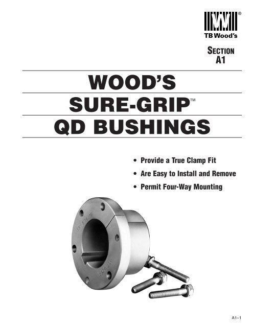
WOOD’S<br />
<strong>SURE</strong>-<strong>GRIP</strong>TM<br />
QD <strong>BUSHINGS</strong><br />
• Provide a True Clamp Fit<br />
• Are Easy to Install and Remove<br />
• Permit Four-Way Mounting<br />
A1–1
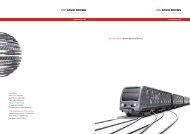
<strong>SURE</strong>-<strong>GRIP</strong> BUSHING FEATURES<br />
Sure-Grip ® “Quick Detachable” bushings are easy to install<br />
and remove. They are split through flange and taper to provide a<br />
true clamp on the shaft that is the equivalent of a shrink fit. All<br />
sizes except JA and QT have a setscrew over the key to help<br />
6-hole drilling (most sizes)<br />
makes installation and<br />
removal quick<br />
and easy.<br />
Keyseat 180°<br />
from split.<br />
Precise taper (3/4 in. per ft. on diameter)<br />
provides proper wedging action.<br />
Saw cut through flange and<br />
taper (and sometimes cut<br />
down into keyway also) to<br />
provide a true clamp fit.<br />
Cap screws used to<br />
secure bushings to<br />
sheave and to remove<br />
bushing from sheave.<br />
maintain the bushing’s position on the shaft until the cap screws<br />
are securely tightened. Sure-Grip bushings have a very gradual<br />
taper (3/4-inch taper per ft. on the diameter) which is about half<br />
the inclined angle of many other bushings. The result is the<br />
Sure-Grip securely clamps the shaft, with twice the force of<br />
those competitive bushings, to provide extreme holding power.<br />
Versatile Sure-Grip bushings permit the mounting of the same<br />
mating part on shafts of different diameters, and the mounting<br />
of different sheaves on the same shaft using the same bushing.<br />
Their interchangeability extends through sheaves, pulleys,<br />
timing pulleys, sprockets, flexible and rigid couplings, made-toorder<br />
items by Wood’s, and to product lines of several other<br />
mechanical power transmission manufacturers.<br />
Sure-Grip bushings are manufactured with the drilled and<br />
tapped holes located at a precise distance from the keyseat;<br />
thus, a wide mating part having a bushing in each end can be<br />
mounted on a common shaft with the two keyways in line. This<br />
feature not only facilitates installation but also permits both<br />
bushings to carry an equal share of the load.<br />
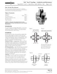
STANDARD MOUNTING<br />
REVERSE MOUNTING<br />
1. Cap screws from outside<br />
through drilled holes in<br />
the mating part and into<br />
threaded holes in the<br />
bushing flange located on<br />
the inside of the assembly.<br />
Or the complete assembly<br />
reversed on the shaft and;<br />
2. Cap screws from inside<br />
through drilled holes in<br />
the mating part and into<br />
threaded holes in the<br />
bushing flange located on<br />
the outside of the assembly.<br />
3. Cap screws from inside<br />
through drilled holes in the<br />
bushing flange located on<br />
the inside of the assembly<br />
and into threaded holes in<br />
the mating part.<br />
4. Cap screws from outside<br />
through drilled holes in the<br />
bushing flange located on<br />
the outside of the assembly<br />
and into threaded holes in<br />
the mating part.<br />
A1–2
<strong>SURE</strong>-<strong>GRIP</strong> BUSHING DIMENSIONS<br />
Sure-Grip bushings are designed to transmit the rated torque capacity listed in the table below when the cap screws are tightened as<br />
indicated. The bushings are stocked in all popular bore sizes, including metric bores, within the bore range for a particular bushing.<br />
Bushing Bushings Bushings<br />
QT JA to J inclusive M to S inclusive<br />
w/Setscrew<br />
w/Setscrew<br />
Except JA<br />
<strong>SURE</strong>-<strong>GRIP</strong> BUSHING<br />
TORQUE RATINGS AND DIMENSIONS<br />
Torque (Note 1) (Note 2)<br />
Cap<br />
DIMENSIONS IN INCHES<br />
Bush. Capacity Max. Max. Bolt Screws<br />
(In.-Lbs.) Bore Bore A B D E F* L Circle Required<br />
QT 1,750 1 1 ⁄2 30 1 /4 1.625 2 1 /2 1 7 /8 1 1 /4 2 2- 1 /4 x 1<br />
JA 1,750 1 1 ⁄4 23 5 /16 1.375 2 11 /16 9 /16 1 1 21 /32 3 - #10 x 1<br />
SH 3,500 1 5 ⁄8 36 3 /8 1.871 2 11 /16 7 /8 13 /16 1 1 /4 2 1 /4 3- 1 /4 x 1 3 /8<br />
SDS 5,000 1 15 ⁄16 42 7 /16 2.1875 3 3 /16 7 /8 3 /4 1 5 /16 2 11 /16 3- 1 /4 x 1 3 /8<br />
SD 5,000 1 15 ⁄16 42 7 /16 2.1875 3 3 /16 1 3 /8 1 1 /4 1 13 /16 2 11 /16 3- 1 /4 x 1 7 /8<br />
SK 7,000 2 1 /2 56 1 /2 2.8125 3 7 /8 1 3 /8 1 1 /4 1 7 /8 3 5 /16 3- 5 /16 x 2<br />
SF 11,000 2 15 /16 63 1 /2 3.125 4 5 /8 1 1 /2 1 1 /4 2 3 7 /8 3- 3 /8 x 2<br />
E 20,000 3 1 /2 78 3 /4 3.834 6 1 7 /8 1 5 /8 2 5 /8 5 3- 1 /2 x 2 3 /4<br />
F 40,000 3 15 /16 90 13 /16 4.4375 6 5 /8 2 13 /16 2 1 /2 3 5 /8 5 5 /8 3- 9 /16 x 3 5 /8<br />
J 55,000 4 1 /2 105 1 5.1484 7 1 /4 3 1 /2 3 3 /16 4 1 /2 6 1 /4 3- 5 /8 x 4 1 /2<br />
M 125,000 5 1 /2 130 1 1 /4 6.500 9 1 /8 5 1 /2 5 3 /16 6 3 /4 7 7 /8 4- 3 /4 x 6 3 /4<br />
N 150,000 6 140 1 1 /2 7.000 10 6 5 /8 6 1 /4 8 1 /8 8 1 /2 4- 7 /8 x 8<br />
P 250,000 7 160 1 3 /4 8.250 11 3 /4 7 5 /8 7 1 /4 9 3 /8 10 4 - 1 x 9 1 /2<br />
W 375,000 8 1 /2 200 2 10.437 15 9 3 /8 9 11 3 /8 12 3 /4 4 - 1 1 /8 x 11 1 /2<br />
S 625,000 10 240 3 1 /4 12.125 17 3 /4 12 1 /2 12 15 3 /4 15 5 - 1 1 /4 x 15 1 /2<br />
* Mating hub length.<br />
1. MAX INCH BORE WITH KEYSEAT.<br />
2. MAX MM BORE WITH STANDARD KEYSEAT.<br />
See pages A1–4 to A1–8 for Bore and Keyseat information and weights.<br />
A1–3
<strong>SURE</strong>-<strong>GRIP</strong> <strong>BUSHINGS</strong><br />
BORE AND KEYSEAT DIMENSIONS<br />
(Inches)<br />
Sure-Grip Bushings are available from stock with all the bores and keyseats listed below. In some cases, as the<br />
bore increases in diameter, a shallow keyseat is provided—due to insufficient metal thickness. When this<br />
happens, Wood’s furnishes the correct rectangular key to suit at no charge. This does not affect the bushing’s<br />
ability to transmit the load. The rectangular key, or flat key as some call it, fits into the standard keyway in the<br />
shaft.<br />
Product<br />
Wt.<br />
No. Bore Key Seat (*)<br />
QT <strong>BUSHINGS</strong><br />
QTMPB 7/16 No KS .6<br />
QT12 1/2 1/8 x 1/16 .6<br />
QT9/16 9/16 1/8 x 1/16 .6<br />
QT58 5/8 3/16 x 3/32 .6<br />
QT11/16 11/16 3/16 x 3/32 .6<br />
QT34 3/4 3/16 x 3/32 .6<br />
QT13/16 13/16 3/16 x 3/32 .6<br />
QT78 7/8 3/16 x 3/32 .6<br />
QT15/16 15/16 1/4 x 1/8 .6<br />
QT1 1 1/4 x 1/8 .6<br />
QT1116 1-1/16 1/4 x 1/8 .6<br />
QT118 1-1/8 1/4 x 1/8 .6<br />
QT1316 1-3/16 1/4 x 1/8 .6<br />
QT114 1-1/4 1/4 x 1/8 .6<br />
QT1516 1-5/16 5/16 x 1/16 .6<br />
QT138 1-3/8 5/16 x 1/16 .6<br />
QT1716 1-7/16 3/8 x 1/16 .6<br />
QT112 1-1/2 3/8 x 1/16 .6<br />
JA <strong>BUSHINGS</strong><br />
JAMPB 1/2 No KS .8<br />
JA12 1/2 1/8 x 1/16 .8<br />
JA9/16 9/16 1/8 x 1/16 .8<br />
JA58 5/8 3/16 x 3/32 .8<br />
JA11/16 11/16 3/16 x 3/32 .8<br />
JA34 3/4 3/16 x 3/32 .8<br />
JA13/16 13/16 3/16 x 3/32 .8<br />
JA78 7/8 3/16 x 3/32 .8<br />
JA15/16 15/16 1/4 x 1/8 .8<br />
JA1 1 1/4 x 1/8 .8<br />
JA1116 1-1/16 1/4 x 1/16 .8<br />
JA118 1-1/8 1/4 x 1/16 .8<br />
JA1316 1-3/16 1/4 x 1/16 .8<br />
JA114 1-1/4 1/4 x 1/32 .8<br />
SH <strong>BUSHINGS</strong><br />
SHMPB 7/16 No KS 1.1<br />
SH12 1/2 1/8 x 1/16 1.1<br />
SH9/16 9/16 1/8 x 1/16 1.1<br />
SH58 5/8 3/16 x 3/32 1.1<br />
SH11/16 11/16 3/16 x 3/32 1.0<br />
SH34 3/4 3/16 x 3/32 1.0<br />
SH13/16 13/16 3/16 x 3/32 1.0<br />
SH78 7/8 3/16 x 3/32 1.0<br />
SH15/16 15/16 1/4 x 1/8 1.0<br />
SH1 1 1/4 x 1/8 .9<br />
* Approximate weight in lbs.<br />
Product<br />
Wt.<br />
No. Bore Key Seat (*)<br />
SH <strong>BUSHINGS</strong> (continued)<br />
SH1116 1-1/16 1/4 x 1/8 .9<br />
SH118 1-1/8 1/4 x 1/8 .9<br />
SH1316 1-3/16 1/4 x 1/8 .8<br />
SH114 1-1/4 1/4 x 1/8 .8<br />
SH1516 1-5/16 5/16 x 5/32 .7<br />
SH138 1-3/8 5/16 x 5/32 .7<br />
SH1716 1-7/16 3/8 x 1/16 .7<br />
SH112 1-1/2 3/8 x 1/16 .6<br />
SH1916 1-9/16 3/8 x 1/16 .6<br />
SH158 1-5/8 3/8 x 1/16 .5<br />
SH11116 1-11/16 No KS .5<br />
SDS <strong>BUSHINGS</strong><br />
SDSMPB 7/16 No KS 1.7<br />
SDS12 1/2 1/8 x 1/16 1.7<br />
SDS9/16 9/16 1/8 x 1/16 1.7<br />
SDS58 5/8 3/16 x 3/32 1.6<br />
SDS11/16 11/16 3/16 x 3/32 1.6<br />
SDS34 3/4 3/16 x 3/32 1.6<br />
SDS13/16 13/16 3/16 x 3/32 1.6<br />
SDS78 7/8 3/16 x 3/32 1.5<br />
SDS15/16 15/16 1/4 x 1/8 1.5<br />
SDS1 1 1/4 x 1/8 1.5<br />
SDS1116 1-1/16 1/4 x 1/8 1.4<br />
SDS118 1-1/8 1/4 x 1/8 1.4<br />
SDS1316 1-3/16 1/4 x 1/8 1.4<br />
SDS114 1-1/4 1/4 x 1/8 1.3<br />
SDS1516 1-5/16 5/16 x 5/32 1.3<br />
SDS138 1-3/8 5/16 x 5/32 1.2<br />
SDS13838KS 1-3/8 3/8 x 3/16 1.2<br />
SDS1716 1-7/16 3/8 x 3/16 1.2<br />
SDS112 1-1/2 3/8 x 3/16 1.1<br />
SDS1916 1-9/16 3/8 x 3/16 1.1<br />
SDS158 1-5/8 3/8 x 3/16 1.0<br />
SDS11116 1-11/16 3/8 x 3/16 1.0<br />
SDS134 1-3/4 3/8 x 1/8 1.0<br />
SDS11316 1-13/16 1/2 x 1/8 .9<br />
SDS178 1-7/8 1/2 x 1/16 .9<br />
SDS11516 1-15/16 1/2 x 1/16 .8<br />
SDS2 2 No KS .7<br />
SD <strong>BUSHINGS</strong><br />
SDMPB 7/16 No KS 2.1<br />
SD12 1/2 1/8 x 1/16 2.1<br />
SD9/16 9/16 1/8 x 1/16 2.1<br />
SD58 5/8 3/16 x 3/32 2.1<br />
SD11/16 11/16 3/16 x 3/32 2.0<br />
MPB Bushings are unsplit.<br />
Product<br />
Wt.<br />
No. Bore Key Seat (*)<br />
SD <strong>BUSHINGS</strong> (continued)<br />
SD34 3/4 3/16 x 3/32 2.0<br />
SD13/16 13/16 3/16 x 3/32 2.0<br />
SD78 7/8 3/16 x 3/32 1.9<br />
SD15/16 15/16 1/4 x 1/8 1.9<br />
SD1 1 1/4 x 1/8 1.8<br />
SD1116 1-1/16 1/4 x 1/8 1.8<br />
SD118 1-1/8 1/4 x 1/8 1.7<br />
SD1316 1-3/16 1/4 x 1/8 1.7<br />
SD114 1-1/4 1/4 x 1/8 1.6<br />
SD1516 1-5/16 5/16 x 5/32 1.6<br />
SD138 1-3/8 5/16 x 5/32 1.5<br />
SD13838KS 1-3/8 3/8 x 3/16 1.5<br />
SD1716 1-7/16 3/8 x 3/16 1.4<br />
SD112 1-1/2 3/8 x 3/16 1.4<br />
SD1916 1-9/16 3/8 x 3/16 1.3<br />
SD158 1-5/8 3/8 x 3/16 1.2<br />
SD11116 1-11/16 3/8 x 3/16 1.2<br />
SD134 1-3/4 3/8 x 1/8 1.1<br />
SD11316 1-13/16 1/2 x 1/8 1.1<br />
SD178 1-7/8 1/2 x 1/16 1.0<br />
SD11516 1-15/16 1/2 x 1/16 .9<br />
SD2 2 No KS .8<br />
SK <strong>BUSHINGS</strong><br />
SKMPB 7/16 No KS 3.6<br />
SK12 1/2 1/8 x 1/16 3.6<br />
SK9/16 9/16 1/8 x 1/16 3.6<br />
SK58 5/8 3/16 x 3/32 3.6<br />
SK11/16 11/16 3/16 x 3/32 3.5<br />
SK34 3/4 3/16 x 3/32 3.5<br />
SK13/16 13/16 3/16 x 3/32 3.5<br />
SK78 7/8 3/16 x 3/32 3.4<br />
SK15/16 15/16 1/4 x 1/8 3.4<br />
SK1 1 1/4 x 1/8 3.3<br />
SK1116 1-1/16 1/4 x 1/8 3.3<br />
SK118 1-1/8 1/4 x 1/8 3.2<br />
SK1316 1-3/16 1/4 x 1/8 3.2<br />
SK114 1-1/4 1/4 x 1/8 3.1<br />
SK1516 1-5/16 5/16 x 5/32 3.1<br />
SK151638KS 1-5/16 3/8 x 3/16 3.1<br />
SK138 1-3/8 5/16 x 5/32 3.0<br />
SK13838KS 1-3/8 3/8 x 3/16 3.0<br />
SK1716 1-7/16 3/8 x 3/16 2.9<br />
SK112 1-1/2 3/8 x 3/16 2.9<br />
SK1916 1-9/16 3/8 x 3/16 2.8<br />
SK158 1-5/8 3/8 x 3/16 2.7<br />
SK11116 1-11/16 3.8 x 3/16 2.6<br />
SK134 1-3/4 3/8 x 3/16 2.5<br />
SK13412KS 1-3/4 1/2 x 1/4 2.5<br />
(Continued—next page)<br />
A1–4
<strong>SURE</strong>-<strong>GRIP</strong> <strong>BUSHINGS</strong><br />
BORE AND KEYSEAT DIMENSIONS<br />
(Inches)<br />
A1–5
<strong>SURE</strong>-<strong>GRIP</strong> <strong>BUSHINGS</strong><br />
BORE AND KEYSEAT DIMENSIONS<br />
(Inches)<br />
Product<br />
Wt.<br />
No. Bore Key Seat (*)<br />
J <strong>BUSHINGS</strong> (continued)<br />
J21516 2-15/16 3/4 x 3/8 21.9<br />
J3 3 3/4 x 3/8 21.6<br />
J318 3-1/8 3/4 x 3/8 20.9<br />
J3316 3-3/16 3/4 x 3/8 20.5<br />
J314 3-1/4 3/4 x 3/8 20.1<br />
J3516 3-5/16 7/8 x 7/16 19.6<br />
J338 3-3/8 7/8 x 7/16 19.3<br />
J3716 3-7/16 7/8 x 7/16 18.9<br />
J312 3-1/2 7/8 x 7/16 18.5<br />
J358 3-5/8 7/8 x 7/16 17.7<br />
J31116 3-11/16 7/8 x 7/16 17.2<br />
J334 3-3/4 7/8 x 7/16 16.8<br />
J31316 3-13/16 1 x 1/2 17.4<br />
J378 3-7/8 1 x 3/8 17.0<br />
J31516 3-15/16 1 x 3/8 16.5<br />
J4 4 1 x 1/8 16.1<br />
J418 4-1/8 1 x 1/8 15.2<br />
J4316 4-3/16 1 x 1/8 14.7<br />
J414 4-1/4 1 x 1/8 14.2<br />
J438 4-3/8 1 x 1/8 13.2<br />
J4716 4-7/16 1 x 1/8 12.7<br />
J412 4-1/2 1 x 1/8 12.2<br />
M <strong>BUSHINGS</strong><br />
M11516 1-15/16 1/2 x 1/4 63.7<br />
M2 2 1/2 x 1/4 63.3<br />
M2316 2-3/16 1/2 x 1/4 62.3<br />
M214 2-1/4 1/2 x 1/4 61.9<br />
M238 2-3/8 5/8 x 5/16 61.0<br />
M2716 2-7/16 5/8 x 5/16 60.6<br />
M212 2-1/2 5/8 x 5/16 60.1<br />
M258 2-5/8 5/8 x 5/16 59.3<br />
M21116 2-11/16 5/8 x 5/16 58.8<br />
M234 2-3/4 5/8 x 5/16 58.3<br />
M278 2-7/8 3/4 x 3/8 57.2<br />
M21516 2-15/16 3/4 x 3/8 56.7<br />
M3 3 3/4 x 3/8 56.2<br />
M318 3-1/8 3/4 x 3/8 55.2<br />
M3316 3-3/16 3/4 x 3/8 54.6<br />
M314 3-1/4 3/4 x 3/8 54.1<br />
M338 3-3/8 7/8 x 7/16 52.8<br />
M3716 3-7/16 7/8 x 7/16 52.2<br />
M312 3-1/2 7/8 x 7/16 51.6<br />
M358 3-5/8 7/8 x 7/16 50.4<br />
M31116 3-11/16 7/8 x 7/16 49.7<br />
M334 3-3/4 7/8 x 7/16 49.1<br />
M378 3-7/8 1 x 1/2 47.6<br />
M31516 3-15/16 1 x 1/2 46.9<br />
M4 4 1 x 1/2 46.2<br />
M418 4-1/8 1 x 1/2 44.8<br />
M4316 4-3/16 1 x 1/2 44.1<br />
M414 4-1/4 1 x 1/2 43.4<br />
M438 4-3/8 1 x 1/2 41.9<br />
M4716 4-7/16 1 x 1/2 41.2<br />
* Approximate weight in lbs.<br />
Product<br />
Wt.<br />
No. Bore Key Seat (*)<br />
M <strong>BUSHINGS</strong> (continued)<br />
M412 4-1/2 1 x 1/2 40.4<br />
M41116 4-11/16 1-1/4 x 5/8 37.5<br />
M434 4-3/4 1-1/4 x 5/8 36.7<br />
M478 4-7/8 1-1/4 x 1/4 37.8<br />
M41516 4-15/16 1-1/4 x 1/4 37.0<br />
M5 5 1-1/4 x 1/4 36.1<br />
M5316 5-3/16 1-1/4 x 1/4 33.5<br />
M514 5-1/4 1-1/4 x 1/4 32.6<br />
M5716 5-7/16 1-1/4 x 1/4 29.9<br />
M512 5-1/2 1-1/4 x 1/4 28.9<br />
N <strong>BUSHINGS</strong><br />
N21516 2-15/16 3/4 x 3/8 84.1<br />
N3 3 3/4 x 3/8 83.5<br />
N338 3-3/8 7/8 x 7/16 79.3<br />
N3716 3-7/16 7/8 x 7/16 78.6<br />
N312 3-1/2 7/8 x 7/16 77.9<br />
N358 3-5/8 7/8 x 7/16 76.4<br />
N334 3-3/4 7/8 x 7/16 74.9<br />
N378 3-7/8 1 x 1/2 73.1<br />
N31516 3-15/16 1 x 1/2 72.3<br />
N4 4 1 x 1/2 71.5<br />
N4316 4-3/16 1 x 1/2 68.9<br />
N414 4-1/4 1 x 1/2 68.1<br />
N438 4-3/8 1 x 1/2 66.3<br />
N4716 4-7/16 1 x 1/2 65.4<br />
N412 4-1/2 1 x 1/2 64.5<br />
N458 4-5/8 1-1/4 x 5/8 62.0<br />
N434 4-3/4 1-1/4 x 5/8 60.0<br />
N478 4-7/8 1-1/4 x 5/8 58.1<br />
N41516 4-15/16 1-1/4 x 5/8 57.0<br />
N5 5 1-1/4 x 5/8 56.0<br />
N5316 5-3/16 1-1/4 x 1/4 56.1<br />
N5716 5-7/16 1-1/4 x 1/4 51.7<br />
N512 5-1/2 1-1/4 x 1/4 50.6<br />
N578 5-7/8 1-1/2 x 1/4 44.3<br />
N51516 5-15/16 1-1/2 x 1/8 43.9<br />
P <strong>BUSHINGS</strong><br />
P21516 2-15/16 3/4 x 3/8 141.2<br />
P314 3-1/4 3/4 x 3/8 137.6<br />
P3716 3-7/16 7/8 x 7/16 134.9<br />
P312 3-1/2 7/8 x 7/16 134.1<br />
P358 3-5/8 7/8 x 7/16 132.4<br />
P334 3-3/4 7/8 x 7/16 130.6<br />
P378 3-7/8 1 x 1/2 128.5<br />
P31516 3-15/16 1 x 1/2 127.6<br />
P4 4 1 x 1/2 126.7<br />
P414 4-1/4 1 x 1/2 122.7<br />
P438 4-3/8 1 x 1/2 120.7<br />
P4716 4-7/16 1 x 1/2 119.6<br />
P412 4-1/2 1 x 1/2 118.6<br />
P458 4-5/8 1-1/4 x 5/8 115.7<br />
P41116 4-11/16 1-1/4 x 5/8 114.6<br />
Product<br />
Wt.<br />
No. Bore Key Seat (*)<br />
P <strong>BUSHINGS</strong> (continued)<br />
P434 4-3/4 1-1/4 x 5/8 113.5<br />
P478 4-7/8 1-1/4 x 5/8 111.2<br />
P41516 4-15/16 1-1/4 x 5/8 110.0<br />
P5 5 1-1/4 x 5/8 108.8<br />
P5316 5-3/16 1-1/4 x 5/8 105.2<br />
P514 5-1/4 1-1/4 x 5/8 103.9<br />
P5516 5-5/16 1-1/4 x 5/8 102.7<br />
P538 5-3/8 1-1/4 x 5/8 101.4<br />
P5716 5-7/16 1-1/4 x 5/8 100.1<br />
P512 5-1/2 1-1/4 x 5/8 98.8<br />
P534 5-3/4 1-1/2 x 3/4 98.1<br />
P578 5-7/8 1-1/2 x 3/4 95.3<br />
P51516 5-15/16 1-1/2 x 3/4 93.9<br />
P6 6 1-1/2 x 1/4 92.5<br />
P6116 6-1/16 1-1/2 x 1/4 91.0<br />
P614 6-1/4 1-1/2 x 1/4 86.6<br />
P6716 6-7/16 1-1/2 x 1/4 83.5<br />
P612 6-1/2 1-1/2 x 1/4 80.5<br />
P634 6-3/4 1-3/4 x 1/8 74.7<br />
P7 7 1-3/4 x 1/8 68.1<br />
W <strong>BUSHINGS</strong><br />
W414MPB 4-1/4 . . . 247.0 249.0<br />
W478MPB 4-7/8 . . . 234.0 235.0<br />
W514MPB 5-1/4 . . . 225.0 227.0<br />
W578MPB 5-7/8 . . . 209.0 210.0<br />
W612MPB 6-1/2 . . . 191.0 193.0<br />
W714MPB 7-1/4 . . . 167.0 169.0<br />
S <strong>BUSHINGS</strong><br />
S6MPB 6 . . . 445.0 471.0<br />
S8MPB 8 . . . 356.0 381.0<br />
S9MPB 9 . . . 301.0 326.0<br />
MPB bushings are unsplit.<br />
A1–6
<strong>SURE</strong>-<strong>GRIP</strong> <strong>BUSHINGS</strong> (INCHES)<br />
WITH METRIC BORE AND KEYSEAT<br />
BORE AND KEY INFORMATION<br />
Product Bore Wt.<br />
No. (mm) Key ■ (*)<br />
QT <strong>BUSHINGS</strong><br />
QT14MM 14 5 x 5 .6<br />
QT15MM 15 5 x 5 .6<br />
QT16MM 16 5 x 5 .6<br />
QT18MM 18 6 x 6 .6<br />
QT19MM 19 6 x 6 .6<br />
QT20MM 20 6 x 6 .6<br />
QT22MM 22 6 x 6 .6<br />
QT24MM 24 8 x 7 .6<br />
QT25MM 25 8 x 7 .6<br />
QT28MM 28 8 x 7 .6<br />
QT30MM 30 8 x 7 .6<br />
QT32MM 32 10 x 6† .6<br />
QT35MM 35 10 x 6† .6<br />
QT38MM 38 10 x 6† .6<br />
JA <strong>BUSHINGS</strong><br />
JA15MM 15 5 x 5 .8<br />
JA16MM 16 5 x 5 .8<br />
JA19MM 19 6 x 6 .8<br />
JA20MM 20 6 x 6 .8<br />
JA24MM 24 8 x 6† .8<br />
JA25MM 25 8 x 6† .8<br />
JA28MM 28 8 x 5† .8<br />
SH <strong>BUSHINGS</strong><br />
SH24MM 24 8 x 7 .9<br />
SH25MM 25 8 x 7 .9<br />
SH28MM 28 8 x 7 .9<br />
SH30MM 30 8 x 7 .8<br />
SH32MM 32 10 x 8 .8<br />
SH35MM 35 10 x 8 .7<br />
SDS <strong>BUSHINGS</strong><br />
SDS24MM 24 8 x 7 1.5<br />
SDS25MM 25 8 x 7 1.5<br />
SDS28MM 28 8 x 7 1.4<br />
SDS30MM 30 8 x 7 1.4<br />
SDS32MM 32 10 x 8 1.3<br />
SDS35MM 35 10 x 8 1.2<br />
SDS38MM 38 10 x 8 1.1<br />
SDS40MM 40 12 x 8 1.1<br />
SDS42MM 42 12 x 8 1.0<br />
Product Bore Wt.<br />
No. (mm) Key ■ (*)<br />
SK <strong>BUSHINGS</strong><br />
SK24MM 24 8 x 7 3.3<br />
SK25MM 25 8 x 7 3.3<br />
SK28MM 28 8 x 7 3.2<br />
SK30MM 30 8 x 7 3.2<br />
SK32MM 32 10 x 8 3.1<br />
SK35MM 35 10 x 8 3.0<br />
SK38MM 38 10 x 8 2.9<br />
SK40MM 40 12 x 8 3.6<br />
SK42MM 42 12 x 8 2.7<br />
SK45MM 45 14 x 9 2.6<br />
SK48MM 48 14 x 9 2.4<br />
SK50MM 50 14 x 9 2.3<br />
SK55MM 55 16 x 10 2.0<br />
SF <strong>BUSHINGS</strong><br />
SF28MM 28 8 x 7 4.7<br />
SF30MM 30 8 x 7 4.6<br />
SF32MM 32 10 x 8 4.5<br />
SF35MM 35 10 x 8 4.4<br />
SF38MM 38 10 x 8 4.2<br />
SF40MM 40 12 x 8 4.2<br />
SF42MM 42 12 x 8 4.1<br />
SF45MM 45 14 x 9 3.9<br />
SF48MM 48 14 x 9 3.7<br />
SF50MM 50 14 x 9 3.6<br />
SF55MM 55 16 x 10 3.2<br />
SF60MM 60 18 x 11 3.0<br />
SF65MM 65 18 x 8 † 2.6<br />
E <strong>BUSHINGS</strong><br />
E35MM 35 10 x 8 10.2<br />
E38MM 38 10 x 8 10.0<br />
E40MM 40 12 x 8 9.9<br />
E42MM 42 12 x 8 9.8<br />
E45MM 45 14 x 9 9.6<br />
E48MM 48 14 x 9 9.3<br />
E50MM 50 14 x 9 9.2<br />
E55MM 55 16 x 10 8.6<br />
E60MM 60 18 x 11 8.1<br />
E65MM 65 18 x 11 7.6<br />
E70MM 70 20 x 12 7.1<br />
E75MM 75 20 x 12 6.9<br />
E80MM 80 22 x 11† 6.3<br />
Product Bore Wt.<br />
No. (mm) Key ■ (*)<br />
F <strong>BUSHINGS</strong><br />
F45MM 45 14 x 9 16.2<br />
F48MM 48 14 x 9 16.0<br />
F50MM 50 14 x 9 15.8<br />
F55MM 55 16 x 10 15.0<br />
F60MM 60 18 x 11 14.3<br />
F65MM 65 18 x 11 13.7<br />
F70MM 70 20 x 12 12.9<br />
F75MM 75 20 x 12 12.1<br />
F80MM 80 22 x 14 11.2<br />
F85MM 85 22 x 14 10.6<br />
F90MM 90 25 x 14 9.7<br />
J <strong>BUSHINGS</strong><br />
J50MM 50 14 x 9 26.5<br />
J55MM 55 16 x 10 25.6<br />
J60MM 60 18 x 11 24.7<br />
J65MM 65 18 x 11 23.9<br />
J70MM 70 20 x 12 23.0<br />
J75MM 75 20 x 12 21.9<br />
J80MM 80 22 x 14 20.9<br />
J85MM 85 22 x 14 19.3<br />
J90MM 90 25 x 14 18.1<br />
J95MM 95 25 x 14 16.8<br />
J100MM 100 28 x 16 16.5<br />
M <strong>BUSHINGS</strong><br />
M80MM 80 22 x 14 55.0<br />
M90MM 90 25 x 14 51.2<br />
M100MM 100 28 x 16 46.9<br />
M120MM 120 32 x 18 37.0<br />
N <strong>BUSHINGS</strong><br />
N100MM 100 28 x 16 72.3<br />
N120MM 120 32 x 18 60.2<br />
P <strong>BUSHINGS</strong><br />
P150MM 150 36 x 20 95.8<br />
SD <strong>BUSHINGS</strong><br />
SD24MM 24 8 x 7 1.8<br />
SD25MM 25 8 x 7 1.8<br />
SD28MM 28 8 x 7 1.7<br />
SD30MM 30 8 x 7 1.7<br />
SD32MM 32 10 x 8 1.6<br />
SD35MM 35 10 x 8 1.5<br />
SD38MM 38 10 x 8 1.4<br />
SD40MM 40 12 x 8 1.3<br />
SD42MM 42 12 x 8 1.2<br />
*<br />
• Approximate weight in lbs.<br />
■ The metric system does not refer to keyseat or keyway dimensions as does<br />
the English system; instead, dimensions are given for the key itself, which<br />
is rectangular in shape and not square as in the English system. This meets<br />
ISO standards.<br />
† SHALLOW KEY FURNISHED<br />
A1–1<br />
A1–7
<strong>SURE</strong>-<strong>GRIP</strong> BRUSHINGS<br />
INSTALLATION INSTRUCTIONS<br />
The Sure-Grip tapered, QD-type interchangeable bushing offers flexible and easy<br />
installation while providing exceptional holding power. To ensure that the bushing<br />
performs as specified, it must be installed properly.<br />
Before beginning, make sure the correct size and quantity of parts are available for the installation. The bushing has<br />
been manufactured to accept a setscrew over the key and its use is optional. It is packaged with the hardware on sizes<br />
SH to M and loosely installed in the bushing on sizes N to S.<br />
A1–14<br />
To Install:<br />
IMPORTANT:<br />
DO NOT USE LUBRICANTS IN THIS INSTALLATION!<br />
1. Inspect the tapered bore of the sheave and the tapered<br />
surface of the bushing. Any paint, dirt, oil, or grease MUST<br />
be removed.<br />
2. Select the type of mounting (See Fig. 1 or 2) that best suits<br />
your application.<br />
3. STANDARD MOUNTING: Install shaft key. (Note: If key was<br />
furnished with bushing, you must use that key.) Install<br />
bushing on clean shaft, flange end first. If bushing will not<br />
freely slide on the shaft, insert a screwdriver or similar<br />
object into the flange sawcut to act as a wedge to open the<br />
bushing’s bore. Caution: Excessive wedging will split the<br />
bushing. If using the setscrew, tighten it just enough to<br />
prevent the bushing from sliding on the shaft. Caution: Do<br />
not over-tighten setscrew! Slide sheave into position on<br />
bushing aligning the drilled holes in the sheave with the<br />
tapped holes in the bushing flange. (Note: Install M thru S<br />
bushings so that the two tapped holes in the sheave are<br />
located as far away as possible from the bushing’s sawcut.)<br />
Loosely thread the capscrews with lockwashers into the<br />
assembly. DO NOT USE LUBRICANT ON THE<br />
CAPSCREWS!<br />
4. REVERSE MOUNTING: With large end of the taper out,<br />
slide sheave onto shaft as far as possible. Install shaft key.<br />
(See shaft key note in #3 above.) Install bushing onto shaft<br />
so tapered end will mate with sheave. (See wedging note in<br />
#3 above.) If using the setscrew, tighten it enough to prevent<br />
the bushing from sliding on the shaft. Caution: Do not<br />
over-tighten setscrew! Pull the sheave up on the bushing,<br />
aligning the drilled holes in the bushing flange with the<br />
tapped holes in the sheave. Loosely thread the capscrews<br />
with lockwashers into the assembly. DO NOT USE<br />
LUBRICANT ON THE CAPSCREWS!<br />
5. Using a torque wrench, tighten all capscrews evenly and<br />
progressively in rotation to the torque value in Table. There<br />
must be a gap between the bushing flange and sheave hub<br />
when installation is complete. DO NOT OVER-TORQUE!<br />
DO NOT ATTEMPT TO CLOSE GAP BETWEEN<br />
BUSHING FLANGE AND SHEAVE HUB!<br />
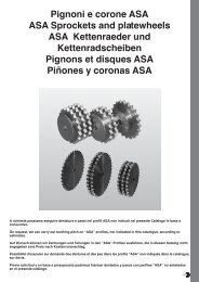
To Remove:<br />
1. Relieve drive tension by shortening the center distance between<br />
driver and driven sheaves.<br />
2. Lift off belts.<br />
3. Loosen and remove cap screws. If the bushings have keyway<br />
setscrews, loosen them.<br />
4. As shown below, insert cap screws (three in JA through J bushings,<br />
two in QT and M thru W bushings and four in S bushing) in tapped<br />
removal holes and progressively tighten each one until mating part<br />
is loose on bushing. (Exception: If mating part is installed with cap<br />
screw heads next to motor, with insufficient room to insert screws<br />
in tapped holes, loosen cap screws and use wedge between<br />
bushing flange and mating part.)<br />
5. Remove mating part from bushing and, if necessary, bushing from<br />
shaft.<br />
<strong>SURE</strong>-<strong>GRIP</strong> <strong>BUSHINGS</strong><br />
SCREW TIGHTENING INFORMATION<br />
Size & Ft.-Lbs.<br />
Tapered Thread of To Apply With<br />
Bushing Cap Screw Torque Wrench<br />
QT 1/4 x 20 9<br />
JA No. 10 – 24 5<br />
SH–SDS–SD 1/4 – 20 9<br />
SK 5/16 – 18 15<br />
SF 3/8 – 16 30<br />
E 1/2 – 13 60<br />
F 9/16 – 12 110<br />
J 5/8 – 11 135<br />
M 3/4 – 10 225<br />
MS 3/4 – 10 150<br />
N 7/8 – 9 300<br />
NS 7/8 – 9 200<br />
P 1 – 8 450<br />
PS 1 – 8 300<br />
W 1-1/8 – 7 600<br />
WS 1-1/8 – 7 400<br />
S 1-1/4 – 7 750<br />
SS 1-1/4 – 7 500<br />
CAUTION: The tightening force on the screws is multiplied many times by the<br />
wedging action of the tapered surface. If extreme tightening force is applied, or if a<br />
lubricant is used, bursting pressures will be created in the hub of the mating part.