Probing Systems For Co-ordinate Measuring machines - Teknikel
Probing Systems For Co-ordinate Measuring machines - Teknikel
Probing Systems For Co-ordinate Measuring machines - Teknikel

You also want an ePaper? Increase the reach of your titles
YUMPU automatically turns print PDFs into web optimized ePapers that Google loves.
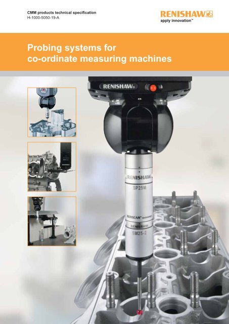
CMM products technical specification<br />
H-1000-5050-19-A<br />
<strong>Probing</strong> systems for<br />
co-<strong>ordinate</strong> measuring <strong>machines</strong>
Introduction<br />
Renishaw’s technology<br />
Renishaw stands at the forefront of<br />
automated metrology, with the Group’s<br />
products providing manufacturers with<br />
the ability to machine components<br />
accurately, and perform measurement<br />
traceable to international standards.<br />
Probe technology, allows fast, highly<br />
repeatable measurements to be carried<br />
out on co-<strong>ordinate</strong> measuring <strong>machines</strong><br />
(CMMs).<br />
A wide range of automated probing<br />
systems has been developed to meet<br />
the needs of post-process inspection,<br />
for quality control.<br />
During the manufacturing operation,<br />
probes used on computer numerically<br />
controlled (CNC) machine tools<br />
provide the measurement capability<br />
to automatically control the machining<br />
process. This eliminates the need<br />
for costly, time consuming manual<br />
procedures.<br />
Renishaw gives extra capability to CNC<br />
machine tools and CMMs by enabling<br />
scanning and digitising of 3-dimensional<br />
(3D) forms to generate the necessary<br />
NC programs to produce either replica<br />
parts, or moulds and dies.<br />
Renishaw has developed the Cyclone<br />
scanning machine and associated<br />
software, a cost-effective solution to<br />
stand-alone digitising.<br />
The revolutionary manufacturing<br />
system, RAMTIC (Renishaw’s<br />
automated milling, turning and<br />
inspection centre), maximises the<br />
potential of existing machine tools,<br />
enabling milling, turning and inspection<br />
on a single machine, together with<br />
automated loading and unloading of<br />
materials and tools.<br />
CNC machine tools and CMMs benefi t<br />
from regular volumetric checking by<br />
Renishaw’s automated ball-bar and<br />
machine checking gauge.<br />
<strong>Co</strong>mprehensive machine calibration<br />
can be undertaken, when necessary,<br />
using Renishaw’s innovative laser<br />
calibration systems.<br />
Renishaw has developed linear scale,<br />
laser interferometer and encoder<br />
systems for fi tting to a variety of<br />
<strong>machines</strong>, to provide axis displacement<br />
measurement. Dedicated lengths of<br />
rigid scale are not required, since<br />
Renishaw’s approach has been to<br />
produce fl exible scale that can be<br />
dispensed from a reel and cut to the<br />
required length.<br />
Renishaw has also applied its<br />
innovatory approach to produce a<br />
Raman microscope and accessories for<br />
2D spectral analysis of materials in a<br />
non-destructive manner.<br />
From its leading market position, the<br />
Renishaw Group continues to expand<br />
its product range into ever increasing<br />
business sectors worldwide. Identifying<br />
and targeting new market opportunities<br />
has led to the continuous development<br />
and introduction of new, highly<br />
innovative products which signifi cantly<br />
enhance the manufacturing capabilities<br />
in a wide range of industries.
<strong>Probing</strong> systems for<br />
co-<strong>ordinate</strong> measuring <strong>machines</strong><br />
Introduction to CMM probing<br />
CMMs are used for a wide variety of industry applications,<br />
especially for post-process inspection of manufactured<br />
components. Renishaw’s probes and probing systems have<br />
become the industry choice for rapid and accurate inspection.<br />
CMMs, which act as a quality reference, use probing<br />
systems to replace traditional manually operated measuring<br />
instruments such as micrometers, vernier callipers and<br />
dedicated gauges.<br />
Probe systems<br />
Renishaw’s probe systems are available in a wide variety of<br />
types to enable a best match for a particular application.<br />
Fitting the probe on the CMM<br />
The probe is mounted on the CMM via a probe head. The<br />
type of head is determined by the fl exibility and automation<br />
required. Renishaw has designed a range of probe heads for<br />
manual and automated systems.<br />
Motorised heads maximise probing effi ciency and give a 3-axis<br />
CMM, 5-axis capability. A motorised head can also be used<br />
with Renishaw’s autochange systems which allows rapid and<br />
automatic exchange of multiple probe types and extension<br />
combinations.<br />
Advanced control<br />
Traditionally, scanning has been limited to relatively slow<br />
<strong>machines</strong> but Renishaw’s universal CMM controller family<br />
enables this function at speeds many times faster than was<br />
previously possible.<br />
Accessories<br />
The range of accessories enhances the basic system by<br />
offering additional capability such as stylus changing for the<br />
probe, probe sensor changing for multiple probe requirements<br />
and extension bars to provide access to deep features.<br />
Renishaw supplies a comprehensive range of styli for<br />
component inspection and scanning applications which are<br />
available in a variety of profi les, sizes and fittings to best<br />
suit the probe employed and the components’ features and<br />
dimensions.<br />
To avoid the risk of compromising measurement performance,<br />
always use a replacement stylus from Renishaw!<br />
<strong>Co</strong>ntents<br />
1 How to use this guide<br />
2 Touch-trigger probes<br />
without stylus module changing<br />
3 Touch-trigger probes<br />
with stylus module changing<br />
4 Scanning probes<br />
5 Manual probe heads<br />
with integral M8/autojoint probe mount<br />
6 Manual probe heads<br />
with integral TP20 stylus module mount<br />
7 Motorised probe heads<br />
servo type<br />
8 Motorised probe heads<br />
indexing type<br />
9 Interfaces and controllers<br />
10 Change/storage racks<br />
for autojointed probes/extensions<br />
11 Extension bars<br />
12 Shanks<br />
13 Accessories<br />
14 Styli and custom design service<br />
15 Glossary of terms<br />
16 Product index
<strong>Probing</strong> systems for<br />
co-<strong>ordinate</strong> measuring <strong>machines</strong><br />
How to use this guide<br />
How to use this guide<br />
1-1<br />
This TECHNICAL SPECIFICATIONS document is intended<br />
to help you select the most appropriate probing system for<br />
your CMM. The probing system includes the probe with<br />
stylus, the method of attachment of the probe to the CMM<br />
by use of a probe head or simple shank, and the necessary<br />
probe/head controlling interfaces.<br />
Probe system selection<br />
Before selecting the most appropriate probe system, you<br />
should clearly understand the scope of measurement<br />
applications to be addressed on your CMM. Renishaw’s<br />
product range covers all types of probing requirements,<br />
from simple touch-trigger point measurement through to<br />
advanced part profi le scanning. Where a standard product<br />
proves not to be ideal, Renishaw’s custom design service is<br />
available to accommodate you requirements.<br />
This technical specifi cations document is divided into<br />
sections that focus on the different parts of the probing<br />
system and indicates the particular benefi ts of each product.<br />
The technical information for each product is also given so<br />
that performance data can be compared where more than<br />
one product appears suitable.<br />
Step-by-step selection procedure<br />
Step 1 (see sections 5, 6, 7 and 8)<br />
<strong>Systems</strong> suitable for your CMM<br />
Q? Which type of CMM do you have or wish to purchase?<br />
Manual CMM - go to sections 5/6 to see the family trees of<br />
probing systems that are suited to manual CMMs. Identify<br />
the probe(s) and probe head(s) that are of interest, and<br />
then proceed to steps 2 and 3 to fi nd out more information<br />
on these products and fi nalise your selection.<br />
DCC CMM - go to sections 7/8 to see the family trees of<br />
probing systems that are suited to DCC CMMs. Identify the<br />
probe(s) and probe head(s) that are of interest, and then<br />
proceed to steps 2 and 3 to fi nd out more information on<br />
these products and fi nalise your selection.<br />
NOTE: All probes shown in this document are suitable for<br />
use on DCC CMMs.<br />
Step 2 (see sections 2/3/4)<br />
Probe selection<br />
Detailed information on each probe is given in one of three<br />
sections as described below.<br />
<strong>Co</strong>ntact trigger probes (see sections 2 and 3)<br />
Discrete point, contact trigger probes (also called<br />
touch-trigger probes) are ideal for inspection of 3<br />
dimensional prismatic parts and known geometries. These<br />
probes are highly versatile and are suitable for a diverse<br />
range of applications, materials and surfaces, and there<br />
is a wide range of accessories available for them. The<br />
probes are segregated into two sections here - probes<br />
without, and probes with stylus module changing.<br />
Stylus module changing is a very important consideration<br />
as it enables higher productivity and the ability to always<br />
select the best measurement solution for the application.<br />
A further distinction between contact trigger probes is<br />
their type of design. There are kinematic probes and<br />
electronic probes to choose from. Probe sizes vary<br />
due to the features of the probe. The larger kinematic<br />
probes are extremely robust and are very well suited to<br />
manual CMMs due to their large overtravel capability. The<br />
smaller probes are suited to applications where there is a<br />
need to access restricted spaces. Renishaw’s electronic<br />
probes offer extended life suitable for high density point<br />
profi le measurement and also permit higher accuracy<br />
than kinematic probes. Depending on the type of CMM<br />
and the level of utility required, there is a choice between<br />
shank mounted, M8 thread or autojoint mounted probes.<br />
Renishaw’s autojoint mounted probes and extensions<br />
can be rapidly interchanged for increased fl exibility and<br />
productivity.<br />
<strong>Co</strong>ntact scanning probes (see section 4)<br />
Scanning is ideal for the inspection of geometric forms<br />
and full profi le measurement where thousands of data<br />
points can describe the form more fully than a few discrete<br />
points. A large amount of information can be collected in<br />
a very short time giving better direct results. Renishaw’s<br />
range of fi xed and indexable type scanning probes offers<br />
high accuracy, excellent robustness and low contact force<br />
scanning. All Renishaw scanning probes feature rapid<br />
interchange between stylus confi gurations to further<br />
increase fl exibility and productivity.
Step 3 (see sections 5/6/7/8)<br />
Probe head selection<br />
Having selected the probe type, refer again to the family<br />
trees (sections 5 and 6 for manual CMMs or sections 7 and<br />
8 for DCC CMMs) to see which probe head(s) are suitable.<br />
Manual CMMs - are usually fi tted with shank-mounted<br />
probes or manual probe heads. Renishaw offer varieties of<br />
manual probe heads which are segregated into sections<br />
5/6 here detailing manual probe heads with integral M8/<br />
autojoint or with integral TP20 stylus module mount.<br />
A further design consideration is the choice of fixed or<br />
articulating/indexing manual head types. The type of<br />
probe head required can be determined by examining<br />
the features of each head and matching them to your<br />
requirements.<br />
DCC CMMs - can be fi tted with either manual or motorised<br />
probe head systems, so the choice must be made having<br />
considered the applications of the CMM. Motorised heads<br />
are segregated into sections 7/8 here detailing servo type<br />
and indexing type motorised heads. Fitting the probe<br />
on a CMM using a motorised head is the easiest way to<br />
vastly improve the capability of the CMM and maximise<br />
productivity. The indexing type motorised heads are<br />
designed to position the probe at one of 720 positions,<br />
in 7.5° steps, so probing can be carried out at many<br />
angles. The repeatability of the head means that these<br />
positions can be recalled at any time without the need for<br />
re-qualifi cation. This can save a great deal of time for the<br />
operator, and encourages system optimisation by applying<br />
the probe to the surface at the best angle for the most<br />
accurate result. Servo type motorised heads provide almost<br />
unlimited angular positioning and are ideally suited to<br />
horizontal arm CMMs.<br />
Step 4 (see section 9)<br />
Probe / probe head, interface selection<br />
The probe data in sections 2, 3 and 4 defi nes the electrical<br />
interface(s) compatible with the chosen probe. See section<br />
9 for full details of probe interfaces.<br />
The probe head data in sections 5, 6, 7 and 8 defi nes<br />
the type of controller required to integrate the probe head<br />
into the CMM. See section 9 for full details of probe head<br />
interfaces.<br />
Step 5 (see sections 11 and 12)<br />
Extension bar / shank selection<br />
<strong>For</strong> probes and probe heads that are shank mounted on the<br />
CMM, go to section 12 to choose the appropriate shank.<br />
Section 11 details a comprehensive range of extension bars<br />
to enhance the versatility of your probe system. Remember<br />
that Renishaw offers a custom design service if the type<br />
of shank/extension you require is not a standard product.<br />
Step 6 (see sections 2, 3, 4 and 10)<br />
Changer system selection<br />
Many of Renishaw’s probes, when fi tted to DCC CMMs,<br />
are capable of rapid automatic interchange between<br />
stylus configurations or even between different types<br />
of probe. Refer to sections 2, 3 and 4 to see if your chosen<br />
probe has change rack compatibility, and for details of these<br />
highly productive systems. Renishaw’s autochange rack<br />
systems allow rapid exchange between probe sensors<br />
and extensions with the Renishaw autojoint and are<br />
detailed in section 10.<br />
Step 7 (see section 13)<br />
Accessories<br />
Check the accessories section 13, for other accessories<br />
available for your chosen probe system.<br />
Step 8 (see section 14)<br />
Stylus selection<br />
Renishaw produces a wide range of styli designed to<br />
optimise measurement performance. A brief overview is<br />
given in section 14. Please also see Renishaw’s Styli<br />
and accessories guide (part number H-1000-3200) for<br />
comprehensive details.<br />
NOTE: Section 15 contains a glossary of terms used in this<br />
document.<br />
This document contains information on Renishaw’s current<br />
CMM products range. If you require additional information<br />
on these and discontinued products, please visit our<br />
website: www.renishaw.com<br />
How to use this guide<br />
1-2
<strong>Probing</strong> systems for<br />
co-<strong>ordinate</strong> measuring <strong>machines</strong><br />
TP7M / TP7M EP probes<br />
The TP7M range comprises electronic probes using<br />
Touch-trigger probes<br />
without stylus module changing<br />
2-1<br />
strain gauge technology which gives higher accuracy<br />
than kinematic touch-trigger probes. Incorporating a<br />
multiwired autojoint connection, the TP7M is compatible<br />
with the PH10M/PH10MQ motorised heads, PH6M fixed<br />
probe head, and the range of PEM extension bars.<br />
The autojoint also allows fast probe changing, either<br />
manually or automatically, with a Renishaw autochange<br />
rack system.<br />
The enhanced performance TP7M EP is capable<br />
of achieving a 3D accuracy of
TP2-5W probes<br />
M8 × 1.25 thread<br />
The TP2-5W is one of Renishaw’s best known products. It is a 13 mm (0.51 in)<br />
diameter standard kinematic touch-trigger probe with an M8 thread mount. Its<br />
adjustable stylus force enables the probe to support a wide range of styli.<br />
The TP2 is small, light and compatible with a wide range of accessories, and<br />
is suitable for manual and DCC CMMs.<br />
Ø13 mm<br />
TP2-5W features and benefits:<br />
(0.52 in)<br />
• Small, light, versatile probe<br />
• Adjustable trigger force<br />
3 mm<br />
• <strong>Co</strong>mpatible with M2 styli<br />
(0.12 in)<br />
• <strong>Co</strong>mpatible with the full range of Renishaw probe<br />
heads and accessories<br />
M2 × 0.4 thread<br />
9 mm (0.35 in)<br />
38 mm (1.5 in)<br />
Touch-trigger probes<br />
without stylus module changing<br />
2-2<br />
• Suitable for manual and DCC CMMs<br />
Maximum<br />
XY overtravel<br />
14° 14°<br />
TP1 (S) probe<br />
This large, robust kinematic probe has a high degree of overtravel and is<br />
shank mounted, making it ideal for use on manual CMMs. The probe signal is<br />
carried to the CMM via an external cable and the probe has adjustable stylus<br />
force to help optimise its performance.<br />
+Z overtravel<br />
4.0 mm (0.16 in)<br />
TP1(S) features and benefits:<br />
• Ideal for manual CMMs<br />
• Robust<br />
Ø46 mm<br />
(1.8 in)<br />
15 mm (0.59 in)<br />
46 mm (1.8 in)<br />
• Large overtravel range<br />
M3 × 0.5 thread<br />
• Large adjustable trigger force range<br />
• Shank mounted<br />
Maximum<br />
XY overtravel<br />
19.5° 19.5°<br />
+Z overtravel<br />
8.5 mm (0.34 in)<br />
Specification summary TP2-5W TP1(S)<br />
PRINCIPAL APPLICATION Universal DCC and manual CMMs. Manual CMMs.<br />
SENSE DIRECTIONS 5-axis: ±X, ±Y, +Z 5-axis: ±X, ±Y, +Z<br />
UNIDIRECTIONAL REPEATABILITY MAXIMUM<br />
(2σ µm) (at stylus tip)<br />
0.35 µm (0.000014 in) 0.50 µm (0.00002 in)<br />
PRE-TRAVEL VARIATION 360° (XY PLANE) ±0.80 µm (0.000032 in) ±2 µm (0.00008 in)<br />
WEIGHT *excluding shank and cable 22 g (0.78 oz) 128 g* (4.52 oz*)<br />
STYLUS RANGE M2 M3<br />
STYLUS FORCE RANGE (ADJUSTABLE) 0.07 N - 0.15 N 0.1 N - 0.5 N<br />
STYLUS FORCE (SET BY RENISHAW) 0.07 N - 0.08 N 0.15 N<br />
STYLUS OVERTRAVEL (TYPICAL)<br />
XY PLANE<br />
±14°<br />
±19.5°<br />
+Z axis<br />
4 mm (0.16 in) @ 0.07 N<br />
3 mm (0.12 in) @ 0.15 N<br />
8.5 mm (0.34 in) @ 0.1 N<br />
5 mm (0.20 in) @ 0.5 N<br />
MAXIMUM EXTENSION ON PH10 SERIES 300 mm (11.81 in) N/A<br />
MOUNTING METHOD M8 thread Shank to suit machine<br />
SUITABLE INTERFACE PI 4-2, PI 7-2, PI 200, UCC PI 4-2, PI 7-2, PI 200, UCC<br />
Above data applies to test conditions as follows: Stylus length 10 mm (0.39 in) [re TP2-5W] or 31 mm (1.22 in) [re TP1(S)].<br />
Stylus velocity 480 mm/min (1.57 ft/min). Stylus force 0.07-0.08 N [re TP2-5W] or 0.15 N [re TP1(S)].
<strong>Probing</strong> systems for<br />
co-<strong>ordinate</strong> measuring <strong>machines</strong><br />
TP6 / TP6A probes<br />
M8 × 1.25 thread<br />
The TP6 is an M8 thread mounted probe while<br />
the TP6A has an autojoint, which means that it<br />
Touch-trigger probes<br />
without stylus module changing<br />
2-3<br />
can be changed quickly and easily without the<br />
need to re-qualify stylus tips. The probe design<br />
is robust with large overtravel and adjustable<br />
trigger force.<br />
TP6 / TP6A features and benefits:<br />
• Autojoint or M8 version<br />
• Long stylus carrying capability<br />
Ø25 mm<br />
(0.98 in)<br />
6.5 mm<br />
(0.26 in)<br />
M3 × 0.5 thread<br />
22° 22°<br />
Maximum<br />
XY overtravel<br />
15 mm (0.59 in)<br />
41 mm (1.61 in)<br />
+Z overtravel<br />
5.5 mm (0.22 in)<br />
• Large stylus overtravel<br />
• Robust<br />
• Adjustable trigger force range<br />
• M3 stylus mount<br />
Ø25 mm<br />
(0.98 in)<br />
6.5 mm<br />
(0.26 in)<br />
15 mm (0.59 in)<br />
46.5 mm (1.83 in)<br />
49 mm (1.93 in)<br />
22° 22°<br />
+Z overtravel<br />
5.5 mm (0.22 in)<br />
Maximum<br />
XY overtravel<br />
Specification summary TP6 TP6A<br />
PRINCIPAL APPLICATION<br />
Robust universal DCC and<br />
manual CMMs.<br />
As TP6 but with fast<br />
probe exchange without<br />
requalifi cation.<br />
SENSE DIRECTIONS 5-axis: ±X, ±Y, +Z 5-axis: ±X, ±Y, +Z<br />
UNIDIRECTIONAL REPEATABILITY MAXIMUM<br />
(2σ µm) (at stylus tip)<br />
0.35 µm (0.000014 in) 0.35 µm (0.000014 in)<br />
PRE-TRAVEL VARIATION 360° (XY PLANE) ±1 µm (±0.00004 in) ±1 µm (±0.00004 in)<br />
WEIGHT 56 g (1.98 oz) 76 g (2.68 oz)<br />
STYLUS RANGE M3 M3<br />
STYLUS FORCE RANGE (ADJUSTABLE) 0.11 N - 0.3 N 0.11 N - 0.3 N<br />
STYLUS FORCE (SET BY RENISHAW) 0.11 N - 0.13 N 0.11 N - 0.13 N<br />
STYLUS OVERTRAVEL (TYPICAL)<br />
XY plane<br />
±22°<br />
±22°<br />
+Z axis<br />
5.5 mm (0.22 in) @ 0.11 N<br />
5.5 mm (0.22 in) @ 0.11 N<br />
2 mm (0.08 in) @ 0.3 N<br />
2 mm (0.08 in) @ 0.3<br />
MAXIMUM EXTENSION ON PH10 SERIES 200 mm (7.87 in) 200 mm (7.87 in)<br />
MOUNTING METHOD M8 thread Autojoint<br />
SUITABLE INTERFACE PI 4-2, PI 7-2, PI 200, UCC PI 4-2, PI 7-2, PI 200, UCC<br />
Above data applies to test conditions as follows: Stylus length 21 mm (0.83 in).<br />
Stylus velocity 480 mm/min (1.57 ft/min). Stylus force 0.11-0.13 N
TP200 / TP200B modular probes<br />
The TP200/TP200B are electronic probes using strain<br />
gauge technology, which gives higher accuracy than<br />
kinematic touch-trigger probes. They combine outstanding<br />
metrology performance with superior functionality to<br />
produce a highly versatile DCC CMM probing system with<br />
excellent productivity.<br />
The TP200 system components are:<br />
• TP200 probe body – the standard model<br />
• TP200B probe body – a variant model with increased<br />
vibration tolerance<br />
• TP200 stylus module – choice of fi xed overtravel forces:<br />
‘SF’ (standard force) or ‘LF’ (low force)<br />
There is also the ‘EO’ (extended overtravel) module,<br />
which has the same overtravel force as the ‘SF’ but<br />
provides increased operating range and protection in<br />
the probe Z axis<br />
Touch-trigger probes<br />
with stylus module changing<br />
3-1<br />
• PI 200 probe interface<br />
• SCR200 stylus changing rack<br />
TP200 probe body<br />
The TP200 probe incorporates micro strain gauge<br />
transducers, delivering excellent repeatability and accurate<br />
3D form measurement even with long styli. The sensor<br />
technology gives sub-micron triggering performance and<br />
eliminates the lobing characteristics encountered with<br />
standard probes. The solid-state ASIC electronics within<br />
the probe ensure reliable operation over millions of trigger<br />
points.<br />
TP200B probe body<br />
The TP200B probe uses the same technology as TP200<br />
but has been designed to have a higher tolerance to<br />
vibration. This helps to overcome the problem of ‘air’ trigger<br />
generation which can arise from vibrations transmitted<br />
through the CMM or when using longer styli with faster<br />
positioning speeds.<br />
TP200<br />
probe<br />
body<br />
NOTE: We do not recommend the use of TP200B with the<br />
LF module or cranked/star styli.<br />
TP200<br />
stylus<br />
module
<strong>Probing</strong> systems for<br />
co-<strong>ordinate</strong> measuring <strong>machines</strong><br />
TP200 stylus module<br />
M8 × 1.25 thread<br />
The stylus module is mounted on the probe<br />
Touch-trigger probes<br />
with stylus module changing<br />
3-2<br />
via a highly repeatable magnetic kinematic<br />
joint, providing a rapid stylus changing<br />
capability and probe overtravel protection.<br />
There are three modules available, with two<br />
different overtravel forces:<br />
• The SF (standard force) module is<br />
suitable for most applications.<br />
• The LF (low force) module is<br />
recommended for use with small precision<br />
ball styli or on delicate materials.<br />
• The EO (extended overtravel) module<br />
is recommended for use when<br />
increasing the speed of the CMM<br />
may lead to stopping distances which<br />
exceed the overtravel range provided<br />
in the SF/LF modules. The EO module<br />
has an additional 8 mm (0.32 in) of<br />
overtravel in the probe Z axis to protect<br />
against damage to the sensor in such<br />
circumstances. Overtravel force is the<br />
same as the SF module.<br />
Status LEDs<br />
Ø13.5 mm<br />
(0.53 in)<br />
4 mm<br />
(0.16 in)<br />
M2 × 0.4 thread<br />
14° 14°<br />
Maximum<br />
XY overtravel<br />
Kinematic<br />
plane<br />
5 mm<br />
(0.20 in)<br />
30 mm<br />
(1.18 in)<br />
SF/LF 13 mm (0.51 in)<br />
EO 24 mm (0.95 in)<br />
module not<br />
shown<br />
SF/LF 4.5 mm (0.18 in)<br />
EO 12.5 mm (0.49 in)<br />
+Z overtravel<br />
4 mm (0.16 in)<br />
-Z overtravel by separation of<br />
the module from the sensor<br />
PI 200 probe interface<br />
The PI 200 is a unit capable of the automatic<br />
recognition and interfacing of TP200/B and also<br />
conventional touch-trigger probes (TP2, TP6,<br />
TP20). Two switchable levels of probe trigger<br />
sensitivity are provided to accommodate differing<br />
applications. The PI 200 interface is covered fully<br />
in section 9.<br />
PI 200<br />
SCR200 stylus changing rack<br />
The SCR200 provides rapid, automatic changing<br />
of stylus modules without the need to re-qualify<br />
stylus tips. The SCR200 is powered entirely by<br />
the PI 200 and provides features to facilitate safe<br />
stylus changing.<br />
245 mm (9.65 in)<br />
MSR1 module storage rack<br />
<strong>For</strong> manual storage of modules - see section 13.<br />
Probe maintenance<br />
CK200 (Renishaw part number A-1085-0016) is<br />
a specialised cleaning material supplied for the<br />
removal of contamination from the location faces<br />
of the magnetically retained kinematic couplings<br />
of the TP20, TP200 and SP25M probe systems.<br />
The frequency of cleaning should be determined<br />
according to the conditions of use.<br />
190 mm (7.84 in)<br />
SCR200
TP200 / TP200B features and benefits:<br />
• Excellent repeatability and precision 3D form<br />
measurement<br />
• Rapid exchange between stylus confi gurations<br />
without the need to re-calibrate<br />
• 6-way measuring capability (±X, ±Y, ±Z)<br />
• SF and LF modules to give overtravel force to suit<br />
the application<br />
• EO module to give increased overtravel in probe<br />
Z axis<br />
• Zero reseat errors and no lobing effect<br />
• Suitable for intensive ‘peck’ or ‘stitch’ scanning<br />
• Stylus reach up to 100 mm (3.99 in) GF range<br />
Touch-trigger probes<br />
with stylus module changing<br />
3-3<br />
• Module life of >10 million triggers<br />
• <strong>Co</strong>mpact size<br />
• <strong>Co</strong>mpatible with the full range of Renishaw probe<br />
heads and accessories<br />
Specification summary TP200 TP200B<br />
PRINCIPAL APPLICATION<br />
DCC CMM where high accuracy<br />
is required.<br />
As TP200 but where ‘air’* trigger<br />
events occur.<br />
SENSE DIRECTIONS 6-axis: ±X, ±Y, ±Z 6-axis: ±X, ±Y, ±Z<br />
UNIDIRECTIONAL REPEATABILITY<br />
(2σ µm)<br />
Trigger level 1<br />
Trigger level 2<br />
0.40 µm (0.000016 in)<br />
0.50 µm (0.00002 in)<br />
0.40 µm (0.000016 in)<br />
0.50 µm (0.00002 in)<br />
XY (2D) FORM MEASUREMENT<br />
DEVIATION<br />
Trigger level 1<br />
Trigger level 2<br />
±0.80 µm (0.000032 in)<br />
±0.90 µm (0.000036 in)<br />
±1 µm (0.00004 in)<br />
±1.2 µm (0.000047 in)<br />
XYZ (3D) FORM MEASUREMENT<br />
DEVIATION<br />
Trigger level 1<br />
Trigger level 2<br />
±1 µm (0.00004 in)<br />
±1.40 µm (0.000056 in)<br />
±2.50 µm (0.0001 in)<br />
±4 µm (0.00016 in)<br />
REPEATABILITY OF STYLUS<br />
CHANGE<br />
With SCR200<br />
Manual<br />
±0.50 µm (0.00002 in) max.<br />
±1 µm (0.00004 in) max.<br />
±0.50 µm (0.00002 in) max.<br />
±1 µm (0.00004 in) max.<br />
TRIGGER FORCE<br />
(at stylus tip)<br />
XY plane<br />
Z axis<br />
All modules<br />
All modules<br />
0.02 N<br />
0.07 N<br />
0.02 N<br />
0.07 N<br />
OVERTRAVEL<br />
FORCE<br />
(@ 0.50 mm<br />
displacement)<br />
XY plane<br />
Z axis<br />
SF/EO module<br />
LF module<br />
SF/EO module<br />
LF module<br />
0.2 N to 0.4 N<br />
0.1 N to 0.15 N<br />
4.90 N<br />
1.60 N<br />
0.2 N to 0.4 N<br />
0.1 N to 0.15 N<br />
4.90 N<br />
1.60 N<br />
WEIGHT (probe sensor and module) 22 g (0.78 oz) 22 g (0.78 oz)<br />
MAXIMUM EXTENSION (if on a PH10 series head) 300 mm (11.81 in) 300 mm (11.81 in)<br />
MAXIMUM RECOMMENDED<br />
STYLUS LENGTH<br />
(M2 styli range)<br />
SF/EO module<br />
LF module<br />
50 mm (1.97 in) steel to<br />
100 mm (3.94 in) GF<br />
20 mm (0.79 in) steel to<br />
50 mm (1.97 in) GF<br />
50 mm (1.97 in) steel to<br />
100 mm (3.94 in) GF<br />
20 mm (0.79 in) steel to<br />
50 mm (1.97 in) GF<br />
MOUNTING METHOD M8 thread M8 thread<br />
SUITABLE INTERFACE PI 200, UCC PI 200, UCC<br />
STYLUS MODULE CHANGING<br />
RACK<br />
Automatic<br />
Manual<br />
SCR200<br />
MSR1<br />
SCR200<br />
MSR1<br />
Above data applies for test conditions as follows: Stylus length 50 mm (1.97 in) Stylus velocity 480 mm/min (1.57 ft/min).<br />
* Air trigger (or false trigger). The TP200B reduces probe triggers that may be caused by vibrations.
<strong>Probing</strong> systems for<br />
co-<strong>ordinate</strong> measuring <strong>machines</strong><br />
TP20 / TP20 NI modular probes<br />
The TP20 is a 5-way or 6-way kinematic touch-<br />
Touch-trigger probes<br />
with stylus module changing<br />
3-4<br />
trigger probe. Its two piece design comprises a<br />
probe body and detachable stylus module(s),<br />
which gives the ability to change stylus<br />
confi gurations either manually or automatically<br />
without re-qualifi cation of the stylus tips, providing<br />
signifi cant time savings in inspection routines.<br />
A direct replacement for the industry standard<br />
Renishaw TP2 probe, the TP20 probe system<br />
brings a range of new benefi ts to manual and<br />
DCC CMM applications, and can easily be<br />
retrofi tted to existing TP2 installations.<br />
The TP20 can be used on a wide range of<br />
Renishaw’s manual or motorised probe heads,<br />
either by direct mounting using the standard M8<br />
thread or, alternatively, by using a PAA# adaptor<br />
to connect to an autojoint.<br />
TP20 probe<br />
body<br />
TP20<br />
stylus module<br />
(7 variants)<br />
The system components are:<br />
• TP20/TP20 NI probe body<br />
• TP20 stylus module – seven module variants<br />
allow for optimisation of performance to suit<br />
the application<br />
• MCR20 module changing rack – automatic<br />
operation<br />
• The TP20 probe system may be used with<br />
Renishaw’s PI 4-2, PI 7-2 or PI 200 probe<br />
interfaces (see section 9)<br />
M8 × 1.25 thread<br />
TP20 probe body<br />
The TP20 probe body houses one half of the<br />
highly repeatable magnetic kinematic coupling<br />
that attaches the stylus module and body. The<br />
body also contains a magnetic proximity switch<br />
to inhibit triggering of the probe during automatic<br />
module changing with MCR20.<br />
NOTE: If the probe is operated close to<br />
magnetised parts/clamping etc, the probe<br />
trigger may become inhibited. <strong>Co</strong>untermeasures<br />
include the use of long styli, stylus extensions or<br />
body orientation to increase the distance to the<br />
magnetic source. Alternatively, use the TP20 NI<br />
probe body.<br />
Ø13.2 mm<br />
(0.52 in)<br />
3 mm<br />
(0.12 in)<br />
M2 × 0.4 thread<br />
14° 14°<br />
9 mm (0.35 in)<br />
SF/LF/MF/EF 38 mm (1.50 in)<br />
6W 42 mm (1.65 in)<br />
EM1 88 mm (3.46 in)<br />
EM2 113 mm (4.45 in)<br />
+Z overtravel<br />
TP20 NI probe body<br />
The TP20 NI probe differs from the TP20 body in<br />
that it is not affected by magnetic fi elds. However<br />
the probe trigger must be inhibited through<br />
software during change cycles using the MCR20.<br />
Maximum<br />
XY overtravel<br />
+Z overtravel<br />
SF/EM1/EM2 4 mm (0.16 in)<br />
LF<br />
3.1 mm (0.12 in)<br />
MF<br />
3.7 mm (0.15 in)<br />
EF<br />
2.4 mm (0.09 in)<br />
6W<br />
4.5 mm (0.18 in)<br />
-Z overtravel<br />
-Z overtravel<br />
6W 1.5 mm (0.06 in)
TP20 stylus module<br />
The TP20 stylus module houses the kinematic<br />
switching touch sensor mechanism, carries<br />
the stylus assembly and provides overtravel<br />
in ±X, ±Y and +Z axes (or ±Z in the case of<br />
TP20 6-way module). The stylus mounting<br />
thread accepts styli from the Renishaw M2<br />
range.<br />
A range of seven, application specifi c, stylus<br />
modules is available, being identifi ed by<br />
coloured caps:<br />
• SF - Standard force stylus module<br />
(black cap)<br />
• LF - Low force stylus module<br />
(green cap)<br />
10 mm (0.39 in)<br />
30 mm (1.18 in)<br />
50 mm (1.97 in)<br />
60 mm (2.36 in)<br />
LF<br />
SF<br />
MF<br />
EF<br />
6W<br />
EM1<br />
EM2<br />
Touch-trigger probes<br />
with stylus module changing<br />
3-5<br />
• MF - Medium force stylus module<br />
(grey cap)<br />
100 mm (3.94 in)<br />
• EF - Extended force stylus module<br />
(brown cap)<br />
125 mm (4.92 in)<br />
• 6W - 6-way stylus module<br />
(blue cap)<br />
Stylus comparison<br />
• EM1 SF - Standard force extension<br />
module<br />
• EM2 SF - Standard force extension<br />
module<br />
MCR20 module changing<br />
rack<br />
The MCR20 probe module changing rack is<br />
designed to securely store stylus modules<br />
ready for rapid automatic changing, whilst<br />
protecting mating surfaces from any airborne<br />
contaminants within the working environment.<br />
MSR1 module storage rack<br />
<strong>For</strong> manual storage of modules - see<br />
section 13.<br />
145 mm (5.71 in)<br />
200 mm (7.87 in)<br />
15 mm<br />
(0.59 in)<br />
60 mm<br />
(2.36 in)<br />
MCR20<br />
Probe maintenance<br />
CK200 (Renishaw part number A-1085-0016)<br />
is a specialised cleaning material supplied<br />
for the removal of contamination from the<br />
location faces of the magnetically retained<br />
kinematic couplings of the TP20, TP200 and<br />
SP25M probe systems. The frequency of<br />
cleaning should be determined according to<br />
the conditions of use.<br />
Ø55 mm<br />
(2.17 in)
<strong>Probing</strong> systems for<br />
co-<strong>ordinate</strong> measuring <strong>machines</strong><br />
TP20 / TP20 NI features and<br />
benefits:<br />
Touch-trigger probes<br />
with stylus module changing<br />
3-6<br />
• A kinematic touch-trigger probe system<br />
for manual and DCC CMMs<br />
• Rapid exchange between stylus<br />
confi gurations without the need to<br />
re-calibrate<br />
• A choice of seven stylus modules,<br />
giving 5-axis or 6-axis operation,<br />
allow optimisation of probe and stylus<br />
performance to the given application<br />
• Easily retrofi tted to all Renishaw<br />
standard probe heads (M8 or autojoint<br />
fi tting) and compatible with existing TTP<br />
interfaces<br />
• Metrology performance equivalent to<br />
industry proven TP2-5W probe<br />
• <strong>Co</strong>mpatible with the full range of<br />
Renishaw probe heads and accessories<br />
Specification summary (1) TP20 TP20 NI<br />
PRINCIPAL APPLICATION<br />
SENSE DIRECTIONS<br />
PRE-TRAVEL VARIATION<br />
UNIDIRECTIONAL<br />
REPEATABILITY (2σ µm)<br />
(at stylus tip)<br />
All modules except 6W<br />
6W<br />
LF<br />
SF/EM1/EM2<br />
MF<br />
EF<br />
6W<br />
SF/LF/EM1/EM2<br />
MF<br />
EF<br />
6W<br />
DCC and manual CMMs suitable<br />
for most applications.<br />
5-axis: ±X, ±Y, +Z<br />
6-axis: ±X, ±Y, ±Z<br />
±0.60 µm (±0.000023 in)<br />
±0.80 µm (±0.000032 in)<br />
±1 µm (±0.000039 in)<br />
±2 µm (±0.000079 in)<br />
±1.50 µm (±0.000058 in)<br />
±0.35 µm (±0.000014 in)<br />
±0.50 µm (±0.000020 in)<br />
±0.65 µm (±0.000026 in)<br />
±0.80 µm (±0.000032 in)<br />
DCC and manual CMMs where<br />
operation is within a magnetic<br />
fi eld.<br />
5-axis: ±X, ±Y, +Z<br />
6-axis: ±X, ±Y, ±Z<br />
±0.60 µm (±0.000023 in)<br />
±0.80 µm (±0.000032 in)<br />
±1 µm (±0.000039 in)<br />
±2 µm (±0.000079 in)<br />
±1.50 µm (±0.000058 in)<br />
±0.35 µm (±0.000014 in)<br />
±0.50 µm (±0.000020 in)<br />
±0.65 µm (±0.000026 in)<br />
±0.80 µm (±0.000032 in)<br />
±0.50 µm (±0.000020 in)<br />
±1 µm (±0.000040 in)<br />
REPEATABILITY OF STYLUS<br />
CHANGE (maximum)<br />
With MCR20<br />
Manual<br />
±0.50 µm (±0.000020 in)<br />
±1 µm (±0.000040 in)<br />
STYLUS RANGE M2 M2<br />
MOUNTING METHOD M8 thread M8 thread<br />
SUITABLE INTERFACE PI 4-2, PI 7-2, PI 200, UCC PI 4-2, PI 7-2, PI 200, UCC<br />
STYLUS MODULE<br />
Automatic MCR20<br />
MCR20<br />
CHANGING RACK<br />
Manual MSR1<br />
MSR1<br />
Above data applies for test conditions as follows: Stylus length 10 mm (0.39 in). Stylus velocity 480 mm/min (1.57 ft/min)
Specification summary (2)<br />
Module Application guide Maximum extension<br />
on PH10 series head<br />
LF<br />
SF<br />
EM1<br />
EM2<br />
MF<br />
EF<br />
6W<br />
The low force stylus module, identifi ed by a green cap,<br />
is suited to applications that require low trigger force,<br />
e.g. rubber seals.<br />
The standard force stylus modules, identifi ed by black<br />
caps, are suited to the majority of applications.<br />
The medium force stylus module, identifi ed by a grey cap,<br />
is for use where a higher trigger force than standard is<br />
required.<br />
The extended force stylus module is identifi ed by a brown<br />
cap. Typically, this stylus module will only be required with<br />
large stylus assemblies, and where spurious ‘air’ triggers<br />
caused by machine vibration and acceleration, preclude<br />
the use of either SF, LF or MF modules.<br />
The 6-way stylus module, identifi ed by a blue cap, has<br />
been designed for applications requiring measurement in<br />
the –Z direction, for example when measuring the width<br />
of undercuts.<br />
Weight<br />
(body and module)<br />
300 mm (11.81 in) 22 g (0.78 oz)<br />
300 mm (11.81 in)<br />
300 mm (11.81 in)*<br />
300 mm (11.81 in)*<br />
22 g (0.78 oz)<br />
28 g (0.99 oz)<br />
30 g (1.06 oz)<br />
300 mm (11.81 in) 22 g (0.78 oz)<br />
300 mm (11.81 in) 22 g (0.78 oz)<br />
300 mm (11.81 in) 22 g (0.78 oz)<br />
Touch-trigger probes<br />
with stylus module changing<br />
3-7<br />
* NOTE: Dependant on CMM used and operating conditions.<br />
Specification summary (3)<br />
Module type<br />
and text<br />
stylus length<br />
LF<br />
10 mm<br />
SF<br />
EM1<br />
EM2<br />
10 mm<br />
MF<br />
25 mm<br />
EF<br />
50 mm<br />
6W<br />
10 mm<br />
Trigger force Overtravel force Overtravel displacement<br />
XY Z XY +Z -Z XY +Z -Z<br />
0.06 N 0.65 N 0.09 N 1.15 N - ±14°<br />
0.08 N 0.75 N<br />
0.10 N 1.9 N<br />
0.10 N 3.2 N<br />
0.20 N to<br />
0.30 N<br />
0.20 N to<br />
0.40 N<br />
0.20 N to<br />
0.50 N<br />
3.50 N - ±14°<br />
7 N - ±14°<br />
10 N - ±14°<br />
0.14 N 1.60 N 0.25 N 2.50 N 9 N ±14°<br />
3.10 mm<br />
(0.12 in)<br />
4 mm<br />
(0.16 in)<br />
3.70 mm<br />
(0.15 in)<br />
2.40 mm<br />
(0.09 in)<br />
4.50 mm<br />
(0.18 in)<br />
Above data applies for test conditions as follows: Stylus length as stated above. Stylus velocity 480 mm/min (1.57 ft/min)<br />
-<br />
-<br />
-<br />
-<br />
1.50 mm<br />
(0.06 in)
<strong>Probing</strong> systems for<br />
co-<strong>ordinate</strong> measuring <strong>machines</strong><br />
SP25M compact scanning<br />
probe system<br />
SP25M scanning probe<br />
Scanning probes<br />
4-1<br />
Only 25 mm (0.98 in) in diameter, and with a<br />
range of modules for high performance scanning<br />
and touch-trigger probing, the SP25M is the<br />
world’s most compact and versatile scanning<br />
probe system.<br />
The SP25M is actually two sensors in one,<br />
enabling scanning and touch-trigger probing<br />
in a single probe system. SP25M gives highly<br />
accurate scanning performance with stylus<br />
lengths from 20 mm to 400 mm (0.79 in to<br />
15.75 in) using M3 stylus range. In addition,<br />
the ability to carry Renishaw’s TP20 range of<br />
touch-trigger stylus modules means that the<br />
SP25M system enables best optimisation of the<br />
measurement solution to suit the application.<br />
The SP25M’s compact size and autojoint<br />
mounting make it compatible with the<br />
PH10M/MQ motorised probe heads and PH6M<br />
fi xed probe head. It can also be mounted on<br />
a multiwired extension bar of up to 100 mm<br />
(3.94 in) length. Together, this combination<br />
permits excellent reach and access to part<br />
features.<br />
A unique pivoting design achieves exceptional<br />
dynamic performance. Four scanning modules<br />
have been designed to optimise scanning<br />
accuracy across a wide range of stylus lengths,<br />
avoiding most of the deterioration in performance<br />
seen in other types of scanning probe as stylus<br />
lengths increase.<br />
SM25-4 module can scan very<br />
deep features - shown here<br />
with 400 mm (15.75 in) stylus<br />
SP25M features and benefits:<br />
• The world’s most compact and versatile scanning<br />
probe system<br />
• Two sensors in one - a scanning probe, and a<br />
touch-trigger probe using TP20 stylus modules<br />
• Rapid and repeatable interchange between highly<br />
modular system elements provides the most effi cient<br />
solution to suit the measurement task<br />
• Excellent scanning accuracy across the entire stylus<br />
range of 20 mm to 400 mm (0.79 in to 15.75 in)<br />
• Can be used with extension bars up to 100 mm for<br />
even greater reach<br />
• Ultra-compact at Ø25 mm (Ø0.98 in) for superior part<br />
accessibility<br />
• Isolated optical metrology technology gives unrivalled<br />
measurement performance, even with long styli<br />
• Flexible change rack where ports can be easily<br />
confi gured to carry any system element<br />
• Bump-stop crash protection in the Z axis, together<br />
with a detachable stylus holder for XY crash<br />
protection<br />
• Low-cost, entry level kits available with ability to<br />
easily expand the system<br />
• Probe can be mounted on an articulating head,<br />
allowing access to many features with fewer styli
SP25M modular component<br />
system<br />
SP25M probe body<br />
TM25-20 SM25-1 SM25-2 SM25-3 SM25-4<br />
TP20<br />
module<br />
SH25-1<br />
SH25-2<br />
Scanning probes<br />
4-2<br />
SH25-3<br />
EWL<br />
20 mm to 50 mm<br />
(0.79 in to 1.97 in)<br />
SH25-4<br />
EWL<br />
50 mm to 105 mm<br />
(1.97 in to 4.13 in)<br />
EWL<br />
120 mm to 200 mm<br />
(4.72 in to 7.87 in)<br />
EWL<br />
220 mm to 400 mm<br />
(8.66 in to 15.75 in)<br />
EWL - effective<br />
working length
<strong>Probing</strong> systems for<br />
co-<strong>ordinate</strong> measuring <strong>machines</strong><br />
The SP25M system components<br />
The SP25M probe body, which houses the isolated optical metrology transducer<br />
system, has autojoint compatibility with Renishaw’s PH10M/MQ, and PH6M probe<br />
heads, extension bars and ACR1/3 sensor changers.<br />
Scanning probes<br />
4-3<br />
A range of four scanning modules SM25-1/-2/-3/-4 has been designed to provide<br />
optimised scanning performance over their specifi ed stylus length ranges. The<br />
SP25M’s innovative pivot-action motion, and the isolated optical metrology<br />
approach, mean that excellent accuracy is achieved over the entire stylus length<br />
range of 20 mm to 400 mm (0.79 in to 15.75 in).<br />
SH25-1/-2/-3/-4 stylus holders provide the fl exibility to have multiple stylus set-ups<br />
for each scanning module. The detachable stylus holder is located on the scanning<br />
module using a repeatable magnetic kinematic joint. It provides automatic stylus<br />
changing capability and directly carries Renishaw’s M3 stylus range.<br />
It is also possible to carry Renishaw’s TP20 range of touch-trigger probe modules<br />
by using the TM25-20 adaptor module mounted on the SP25M probe body.<br />
Rapid and repeatable interchange between all system elements allows easy<br />
selection of best probe solution. This can be automated to maximise productivity<br />
by using the FCR25 fl exible change rack.<br />
SP25M with<br />
100 mm (3.94 in)<br />
extension bar<br />
between PH10<br />
head and probe<br />
body<br />
The SP25M can be connected directly to the UCC2 controller while a<br />
daughtercard permits use with Renishaw’s UCC1 controller. The AC3 interface<br />
card allows integration with other controllers.<br />
Using SP25M as a scanning probe:<br />
The probe body has one of the four scanning modules attached (SM25-1/-2/-3/-4)<br />
which have matching stylus holders (SH25-1/-2/-3/-4). Each combination is<br />
optimised to maintain high accuracy and low contact forces over their dedicated<br />
range of effective stylus lengths. These are:<br />
• SM25-1 + SH25-1 = 20 mm to 50 mm (0.79 in to 1.97 in) EWL<br />
by use of 20 mm to 50 mm (0.78 in to 1.97 in) stylus<br />
• SM25-2 + SH25-2 = 50 mm to 105 mm (1.97 in to 4.13 in) EWL<br />
by use of 20 mm to 75 mm (0.78 in to 2.95 in) stylus<br />
• SM25-3 + SH25-3 = 120 mm to 200 mm (4.72 in to 7.87 in) EWL<br />
by use of 20 mm to 100 mm (0.79 in to 3.94 in) stylus<br />
• SM25-4 + SH25-4 = 220 mm to 400 mm (8.66 in to 15.75 in) EWL<br />
by use of 20 mm to 200 mm (0.79 in to 7.87 in) stylus<br />
SP25M scanning<br />
Using SP25M as a touch-trigger probe:<br />
The probe body has the TM25-20 adaptor module attached, which directly carries<br />
any of Renishaw’s TP20 range of stylus modules:<br />
• TP20 LF/SF/MF/EF<br />
• TP20 EM1/EM2<br />
• TP20-6W<br />
Interfacing options<br />
SP25M can be integrated:<br />
• directly using the UCC2 controller (requires scanning upgrade)<br />
• by using Renishaw’s UCC1 controller (requires scanning upgrade) together<br />
with a SP25M/UCC1 daughtercard<br />
• by using Renishaw’s AC3 interface card (ISA Bus) within the<br />
machine builder’s controller<br />
SP25M taking<br />
points with a TP20<br />
module
Automation using the FCR25 flexible<br />
change rack<br />
The full potential of the SP25M system is realised when the<br />
measurement routine is automated using the FCR25 fl exible change<br />
rack, a passive triple-port unit capable of storing any of the system<br />
elements.<br />
The FCR25 port stores the SM25-1/-2/-3/-4 and TM25-20 modules,<br />
but can instantly be confi gured to store the SH25-1/-2/-3/-4 stylus<br />
holders or TP20 modules by using the appropriate port adaptor<br />
insert: PA25-SH (for SH25-1/-2/-3/-4) or PA25-20 (for TP20<br />
modules).<br />
The FCR25 mounts directly on Renishaw’s MRS modular rack<br />
system for multiple port solutions (3, 6, 9, 12, 15 etc). Alternatively,<br />
there are the FCR25-L3 (3 port) and FCR25-L6 (6 port) stand-alone<br />
rack variants that are ideal where machine space is limited.<br />
FCR25’s mounted to the MRS<br />
Scanning probes<br />
4-4<br />
Probe maintenance<br />
CK200 (Renishaw part number A-1085-0016) is a specialised<br />
cleaning material, for the removal of contamination from the location<br />
faces of the magnetically retained kinematic couplings of the TP20,<br />
TP200 and SP25M probe systems. The frequency of cleaning<br />
should be determined according to the conditions of use.<br />
FCR25<br />
39.50 mm<br />
(1.56 in)<br />
28 mm<br />
(1.10 in)<br />
PA25-20<br />
PA25-SH<br />
21.60 mm<br />
(0.85 in)<br />
35 mm (1.38 in)<br />
nominal pitch<br />
113.80 mm<br />
(4.48 in)<br />
74.5 mm<br />
(2.93 in)<br />
219.50 mm<br />
(8.64 in)<br />
113.80 mm<br />
(4.48 in)<br />
166 mm<br />
(6.57 in)<br />
166 mm<br />
(6.57 in)<br />
FCR25-L6 (6 port)<br />
FCR25-L6 (6 port)
<strong>Probing</strong> systems for<br />
co-<strong>ordinate</strong> measuring <strong>machines</strong><br />
SP25M system component dimensions<br />
dimensions mm (in)<br />
2 (0.08) typ.<br />
SM25-4<br />
63.05 (2.48)<br />
SH25-4<br />
Ø5.50 (0.22)<br />
(on SH25-4)<br />
Scanning probes<br />
4-5<br />
310.85 (12.24)<br />
SM25-3<br />
48.05 (1.89)<br />
SH25-3<br />
Ø4 (0.16) typ.<br />
(on SH25-2/3)<br />
SM25-4 Use stylus range<br />
20 to 200 (0.79 to 7.87)<br />
EWL 220 to 400 (8.66 to 15.75)<br />
195.85 (7.71)<br />
SM25-3 Use stylus range<br />
20 to 100 (0.79 to 3.94)<br />
EWL 120 to 200 (4.72 to 7.87)<br />
33.85 (1.33)<br />
SM25-2<br />
SH25-2<br />
111.65 (4.40)<br />
SM25-2 Use stylus range<br />
20 to 75 (0.79 to 2.95)<br />
EWL 50 to 105 (1.97 to 4.13)<br />
26.25 (1.03)<br />
SM25-1<br />
SH25-1<br />
74.05 (2.92)<br />
SM25-1 Use stylus range<br />
20 to 50 (0.79 to 1.97)<br />
EWL 50 to 105 (1.97 to 4.13)<br />
16.95 (0.67)<br />
TM25-20<br />
Ø13.25<br />
(0.52)<br />
TP20<br />
module<br />
62.50 (2.46)<br />
Ø25<br />
(0.98)<br />
SP25M<br />
probe body<br />
45.55 (1.79)
Specification summary SP25M<br />
PROBE ATTRIBUTES Scanning with 3-axis measurement (X, Y, Z)<br />
Touch-trigger probing using TP20 modules *<br />
MEASUREMENT RANGE ±0.50 mm (0.02 in) defl ection in all directions in all orientation<br />
OVERTRAVEL RANGE (nom) X, Y = ±2 mm (±0.08 in) min, +Z - 1.70 mm (0.07 in), -Z = 1.20 mm (0.05 in)<br />
RESOLUTION<br />
Capable of
<strong>Probing</strong> systems for<br />
co-<strong>ordinate</strong> measuring <strong>machines</strong><br />
SP80 - ultra-high accuracy<br />
scanning probe<br />
The SP80 is a passive scanning probe using<br />
digital scale and readheads which enable a<br />
system resolution of 0.02 µm (0.00000079 in).<br />
This gives exceptional scanning performance,<br />
even with long styli.<br />
Scanning probes<br />
4-7<br />
The SP80 can carry styli up to 800 mm<br />
(31.50 in) long and 500 g (17.64 oz) mass,<br />
including star confi gurations. Unbalanced<br />
star confi gurations do not require<br />
counterbalancing. Kinematic stylus holder<br />
changing allows for the repeatable re-location<br />
of the stylus, optimises stylus arrangements<br />
for each feature, and overcomes the need for<br />
re-qualifi cation.<br />
The SP80 has a kinematic mount that<br />
provides a repeatable connection to the<br />
mating plate mounted on the quill (KM80),<br />
allowing the probe to be easily removed.<br />
Kinematic stylus holders provide crash<br />
protection in the XY plane, and a bump-stop<br />
prevents damage to the probe in the Z axis.<br />
NOTE: Please see the accessories page 13-4<br />
for details of adaptor plates PHA80 and PHA3<br />
which permit rapid interchange between SP80<br />
and PH10MQ indexing motorised head.<br />
Isolated optical metrology system<br />
Using an isolated optical metrology system,<br />
SP80 directly measures the defl ection<br />
of the whole mechanism, thus providing<br />
outstandingly accurate position sensing.<br />
The isolated optical metrology system can<br />
detect sources of variable error such as<br />
thermal and dynamic effects. In contrast,<br />
probes with displacement sensors mounted<br />
to stacked axes suffer from latency under<br />
changing inertial loads, and cannot detect<br />
thermal growth in their mechanisms.<br />
Electrical connection<br />
for readheads<br />
The readheads for each axis are fi xed to the<br />
body of the probe, and measure the defl ection<br />
in each direction. Any inter-axis errors caused<br />
by the arc motion of each pair of parallelacting<br />
springs are directly measured by the<br />
sensor system. Isolated optical metrology<br />
systems have no moving wire connections.<br />
Readheads<br />
attached to<br />
probe body<br />
‘Moving cube’<br />
with scales<br />
Light is refl ected from<br />
the moving cube onto<br />
readhead<br />
Stylus mount<br />
Shaded areas<br />
indicate the<br />
moving parts<br />
Isolated optical metrology
SP80 probe body<br />
SP80 probe kit<br />
The sensor mechanism comprises an arrangement of three<br />
sets of parallel springs, one for each body axis, set in a cube<br />
- hence the body shape. The motion of the stylus is coupled<br />
to a ‘moving cube’ holding graduated refl ective scales - again<br />
one for each axis. The readheads are mounted on the wall of<br />
the probe and the light projected from them is refl ected from<br />
the moving scales. This method of motion detection does not<br />
require any form of moving wire connection.<br />
Interface options<br />
Interfacing the SP80 to a CMM can be achieved by:<br />
• Using an SP80 daughtercard for direct UCC1 or UCC2<br />
integration<br />
• Using a Renishaw PCI counter card (CC6) and the<br />
Renishaw interpolator unit IU80<br />
KM80 kinematic<br />
quill mount<br />
SP80 probe<br />
body<br />
Typical CMM quill<br />
Scanning probes<br />
4-8<br />
• Using interface cards designed by the machine builder and<br />
used in conjunction with an IU80<br />
• Using a counter card and interpolator unit designed by the<br />
machine builder<br />
The IU80 conditions the probe signal to provide a digital<br />
industry standard EIA RS422 quadrature scale output, which<br />
can be accepted by CMM controllers.<br />
Please contact Renishaw for full information on the methods<br />
detailed above.<br />
SH80 stylus<br />
holder<br />
Adjustable<br />
stylus mount<br />
KM80 quill mount<br />
This is fi xed to the quill and provides rapid and repeatable<br />
kinematic mounting of the SP80 body to the CMM.<br />
SH80 stylus holder<br />
The detachable stylus holder is located on the probe body<br />
using a repeatable kinematic joint and magnets. It provides<br />
automatic stylus changing capability and has an M5 stylus<br />
mount attachment. <strong>For</strong> additional fl exibility, this may be rotated<br />
by adjusting a grub screw, and does not need to be removed<br />
from the probe body to make the adjustment.<br />
Two SCP80’s mounted on an MRS<br />
MRS<br />
SCP80 stylus changing port<br />
The SH80 stylus holder can be removed automatically and<br />
replaced on the probe body using an SCP80 mounted on a<br />
modular rack system (MRS). The SCP80 has a spring loaded<br />
mechanism which has been designed to ease the stylus<br />
holders away from the probe body. Using the SCP80, the SP80<br />
pull-off force is reduced to less than 20 N.<br />
PHA3 and PHA80<br />
The PHA3 and PHA80 adaptor plates enable rapid<br />
interchange between PH10MQ (using PHA3) and SP80 (using<br />
PHA80) on the same CMM.<br />
SCP80
<strong>Probing</strong> systems for<br />
co-<strong>ordinate</strong> measuring <strong>machines</strong><br />
SP80 / SH80<br />
A<br />
dimensions in mm (in)<br />
6 (0.24)<br />
View A<br />
KM80<br />
80 (3.15)<br />
Scanning probes<br />
4-9<br />
150 (5.91)<br />
106 (4.17)<br />
SP80 body<br />
80 (3.15)<br />
SH80<br />
15-way<br />
D-type plug<br />
41 (1.61)<br />
21 (0.83)<br />
5 × M5 threaded holes for stylus attachment<br />
11 (0.43)<br />
22 (0.87)<br />
80 (3.15)<br />
KM80 70.5 (2.78)<br />
6<br />
(0.24)<br />
46<br />
(1.81)<br />
70.5<br />
(2.76)<br />
80<br />
(3.15)<br />
17<br />
(0.67)<br />
22.5<br />
(0.89)<br />
35<br />
(1.38)<br />
4 × countersunk holes<br />
to suit M4/M3 quill<br />
attachment screws<br />
SCP80<br />
IU80<br />
140 (5.51)<br />
34<br />
(1.34)<br />
183<br />
(7.21)<br />
128<br />
(5.04)<br />
230<br />
(9.06)<br />
44<br />
(1.73)
SP80 features and benefits:<br />
• Ultra-high accuracy measurement,<br />
provided by digital scale and<br />
readheads<br />
• Long styli carrying capability for<br />
access to deep features<br />
• Isolated optical metrology for direct<br />
accurate measurement of stylus<br />
defl ection<br />
• Kinematic stylus changing for system<br />
fl exibility<br />
• Low inertia mechanism for excellent<br />
dynamic response<br />
• Bump-stop crash protection in the<br />
Z axis, together with a detachable<br />
stylus holder for XY crash protection<br />
Scanning probes<br />
4-10<br />
• No motors, therefore improved thermal<br />
stability and reliability<br />
Specification summary<br />
SP80<br />
PROBE ATTRIBUTES Ultra-high accuracy scanning probe with 3-axis measurement (X, Y, Z)<br />
ORIENTATION<br />
Vertical<br />
SIZE<br />
80 mm (3.15 in) square body, 150 mm (5.91 in) long including stylus holder<br />
QUILL MOUNTING<br />
80 mm (3.15 in) kinematic quill mount (KM80) as standard<br />
Shank mount (SM80) and other custom made adaptor plates available -<br />
contact your nearest Renishaw supplier for details<br />
MEASUREMENT RANGE<br />
±2.50 mm (±0.10 in) X, Y, Z (3-axis measurement)<br />
OVERTRAVEL RANGE<br />
X and Y protected by a kinematic break-out joint on SH80<br />
+Z has a mechanical ‘bump-stop’<br />
RESOLUTION OF SCALES<br />
0.02 µm (0.0000007 in)<br />
SPRING RATE Approximately 1.8 N/mm (X, Y, Z)<br />
WEIGHT<br />
SP80:<br />
SH80 stylus holder:<br />
KM80 quill mount:<br />
860 g (30.34 oz) excluding mount and stylus holder<br />
185 g (6.53 oz)<br />
110 g (3.88 oz)<br />
PULL OFF FORCE OF MODULE<br />
<strong>Probing</strong> systems for<br />
co-<strong>ordinate</strong> measuring <strong>machines</strong><br />
SP600, SP600M and SP600Q<br />
scanning probes<br />
SP600<br />
The SP600 (shank mounting), SP600M (multiwired autojoint<br />
mounting) and SP600Q (fi xed in-quill mounting) are highly<br />
reliable analogue probes which are ideal for profi le scanning<br />
Scanning probes<br />
4-11<br />
and measurement on CMMs.<br />
The SP600 family of scanning probes allow large amounts<br />
of data to be rapidly gathered for inspection and digitising<br />
purposes. Axis movement in each direction (X, Y and Z) is<br />
±1 mm (±0.04 in) (in all orientation positions on a PH10)<br />
and stylus lengths up to 300 mm (11.81 in) can be used<br />
with the SH600 EXT stylus holder.<br />
The SH600 provides overtravel protection, and allows rapid<br />
and repeatable interchange between stylus confi gurations.<br />
This can be automated by using the SCR600 stylus change<br />
rack or alternatively, individual SCP600 stylus change ports<br />
mounted to a MRS.<br />
Ø50 mm<br />
(1.97 in)<br />
1.50 mm<br />
(0.06 in)<br />
12.50 mm<br />
(0.50 in)<br />
SH600<br />
89 mm<br />
(3.50 in)<br />
The probe design gives an excellent self centring fi gure of<br />
SH600 STD / SH600 EXT stylus holders<br />
The SH600 stylus holder provides overtravel protection,<br />
and allows rapid and repeatable interchange between<br />
stylus confi gurations. This can be automated by using<br />
the SCR600 stylus change rack or, alternatively,<br />
individual SCP600 stylus change ports mounted on a<br />
MRS.<br />
SH600<br />
There are two variants, SH600 STD and SH600 EXT,<br />
the difference being the stylus carrying capacity. The<br />
STD can carry up to 200 mm (7.87 in) and the EXT up<br />
to 300 mm (11.81 in) long stylus.<br />
Scanning probes<br />
4-12<br />
SCR600 stylus change rack<br />
235 mm (9.25 in)<br />
The SCR600 is a passive stylus change rack for use<br />
with the SP600 probe family, and requires no electrical<br />
connections. It is protected from overtravel (in the probe<br />
entry direction) by a mechanism in the base which can<br />
be manually reset. It houses up to four SH600 stylus<br />
holders per rack and any number of racks can be used<br />
in a system.<br />
SCR600<br />
31.50 mm<br />
(1.24 in)<br />
225 mm<br />
(8.86 in)<br />
Ø55 mm<br />
(Ø2.17 in)<br />
SCP600 stylus change port<br />
The SCP600 has passive operation like the SCR600<br />
and mounts on the MRS. This allows flexibility for users<br />
to confi gure multiple ports, to suit the application.<br />
MRS<br />
SCP600 ports<br />
mount to MRS<br />
SCP600
<strong>Probing</strong> systems for<br />
co-<strong>ordinate</strong> measuring <strong>machines</strong><br />
SP600 family features and benefits:<br />
• High speed scanning up to 300 mm/s<br />
(11.81 in/s), fast point measurement and high<br />
frequency response<br />
• Low probing forces give maximum application<br />
fl exibility<br />
Scanning probes<br />
4-13<br />
• Three variants; SP600, SP600M and SP600Q<br />
allows the ideal probe match to suit the CMM<br />
• Extremely robust design will withstand<br />
moderate collisions<br />
• Fast interchange between stylus confi gurations<br />
permits the best solution for the application and<br />
increases productivity - automatic changing<br />
with either SCR600 or SCP600 mounted on<br />
MRS<br />
• <strong>Co</strong>mpatible with Renishaw’s autochange<br />
rack systems to allow changing between<br />
Renishaw’s other probes fi tted with an autojoint<br />
• Excellent product life with a MTBF in excess of<br />
50,000 hours gives low cost of ownership<br />
Specification summary<br />
SP600, SP600M and SP600Q<br />
PRINCIPLE APPLICATION<br />
High speed, contact form scanning and fast point measurement applications<br />
PROBE ATTRIBUTES<br />
3-axis measurement X, Y, Z<br />
Linear and parallel motion in all axes<br />
MEASUREMENT RANGE<br />
±1 mm (±0.04 in) X, Y, Z in any attitude using a 300 mm (11.81 in) stylus<br />
OVERTRAVEL RANGE<br />
±X, ±Y and +Z are protected by a kinematic break out joint on the SH600<br />
+Z is protected by a bump-stop design<br />
RESOLUTION<br />
0.1 µm (0.000004 in) with optional AC2 interface design<br />
1 µm (0.00004 in) with optional AC1 interface card<br />
SPRING RATE 1.2 N/mm (7.05 ozf) nominal (X, Y, Z)<br />
STYLI Thread M4 standard range<br />
Length<br />
Mass<br />
200 mm (7.87 in) maximum using SH600 STD<br />
300 mm (11.81 in) maximum using SH600 EXT<br />
20 g (0.7 oz) maximum<br />
POWER SUPPLY +12 V to -12 V, 5 V (±10%)<br />
OUTPUTS (X, Y, Z)<br />
Analogue proportional<br />
Voltage output scaling: 4 V/mm to 8.5 V/mm (dependant on stylus)<br />
WEIGHT<br />
SP600<br />
SP600M<br />
SP600Q<br />
172 g (6.07 oz) excluding stylus<br />
216 g (7.62 oz)<br />
299 g (10.55 oz)<br />
MOUNTING<br />
SP600<br />
SP600M<br />
SP600Q<br />
Adaptors to suit clutch, shank adaptor or CMM shank<br />
Multiwired autojoint<br />
Direct quill mounting to the CMM<br />
SUITABLE INTERFACE<br />
Directly to UCC or<br />
AC1 or AC2 interface cards (ISA bus)<br />
CHANGING RACK OPTIONS<br />
SCR600 4 port rack<br />
SCP600 single port unit(s) mounted to the MRS
Q24885<br />
<strong>Probing</strong> systems for<br />
co-<strong>ordinate</strong> measuring <strong>machines</strong><br />
Manual probe heads<br />
with integral M8/autojoint probe mount<br />
Manual probe heads<br />
PH1 * PH6 **<br />
MIH or MIH-S<br />
5-1<br />
PAA<br />
PK1 PEL1 PEL2 PEL3 PAA2 PAA3<br />
TP20 TP2-5W TP200 ‡*<br />
TP6<br />
M3 / M2<br />
adaptor<br />
M2 thread styli
* PH1 is not compatible with TP200<br />
PH6M †<br />
** PH6 has integral cable<br />
† <strong>Co</strong>mpatible with multiwired systems<br />
(TP7M, SP600M and SP25M)<br />
‡ Specialised interface required<br />
Manual probe heads<br />
with integral M8/autojoint probe mount<br />
5-2<br />
PEM25 PEM1 PEM2 PEM3<br />
PEM25 PEM1<br />
SP600M ‡<br />
TP6A SP25M ‡<br />
TP7M ‡<br />
M4 / M3<br />
adaptor<br />
M3 thread styli<br />
M4 thread styli
<strong>Probing</strong> systems for<br />
co-<strong>ordinate</strong> measuring <strong>machines</strong><br />
* MH20/MH20i are covered in<br />
Manual probe heads<br />
with integral M8/autojoint probe mount<br />
MH8<br />
MH20 *<br />
RTP20<br />
section 6<br />
MH20i *<br />
TP1S<br />
5-3<br />
PEL1<br />
TP2-5W<br />
LF SF MF EF 6W<br />
EM1<br />
STD<br />
EM2<br />
STD<br />
M3 / M2<br />
adaptor<br />
M2 thread styli<br />
M3 thread styli
MIH manual indexing<br />
probe head<br />
The MIH is a versatile manual indexing probe<br />
head. It has programmable indexing positions<br />
using 7.5° increments and has an autojoint<br />
probe mount for fast repeatable probe changing.<br />
These features can increase the productivity of<br />
a manual CMM.<br />
MIH-S manual indexing probe<br />
head<br />
The MIH-S is an enhanced version of the MIH<br />
which enables the feedback of positional status<br />
to the PC over an RS232 serial communication<br />
link, via the MIH-SI interface.<br />
MIH<br />
MIH-S<br />
Manual probe heads<br />
with integral M8/autojoint probe mount<br />
5-4<br />
This enables the CMM computer to:<br />
• Verify that the MIH-S has been moved to<br />
the correct position and locked into place.<br />
• Identify the locked position of the MIH-S.<br />
Measurement performance, functionality and<br />
dimensions are the same as for the MIH.<br />
MIH features and benefits:<br />
• Repeatable indexing in 720 positions<br />
• An integral LCD enables easy<br />
programming of probe orientation<br />
positions<br />
MIH / MIH-S<br />
• 20 probe positions can be memorised<br />
• <strong>Co</strong>mpatible with most Renishaw<br />
probes (excluding all multiwire<br />
e.g. TP7M)<br />
• Capable of carrying up to 300 mm<br />
(11.81 in) extension for deep part<br />
measurement<br />
Please refer to page 5-1 for probe<br />
compatibility information<br />
102 mm (4.0 in)<br />
R 62.5 mm<br />
(2.46 in)<br />
76 mm (3.0 in)<br />
62 mm<br />
(2.44 in)<br />
5.0 mm<br />
(0.19 in)<br />
Specification summary<br />
MIH and MIH-S<br />
HEAD MOUNTING<br />
Shank to suit CMM (MS range)<br />
PROBE MOUNTING<br />
Autojoint (i.e. there is no multiwire capacity)<br />
PROBE STATUS INDICATION<br />
LED<br />
CABLE CONNECTION MIH - 5-pin DIN 180° socket MIH-S - 12-pin Hirose<br />
A AXIS INDEXING<br />
0° to 105° in 7.5° steps = 15 positions<br />
B AXIS INDEXING<br />
±180° in 7.5° steps = 48 positions<br />
WEIGHT<br />
580 g (20.45 oz)<br />
REPEATABILITY OF POSITION (2σ) 1 µm (0.00004 in) when used with a TP6A and 21 mm (0.83 in) stylus<br />
MAXIMUM EXTENSION BAR<br />
300 mm (11.81 in)<br />
MAXIMUM RECOMMENDED TORQUE 0.45 Nm<br />
SUITABLE HEAD INTERFACE PI 4-2, PI 200 or PI 7-2<br />
MIH-S HEAD INTERFACE<br />
Uses MIH-SI interface (RS232 communication)
<strong>Probing</strong> systems for<br />
co-<strong>ordinate</strong> measuring <strong>machines</strong><br />
Manual probe heads<br />
with integral M8/autojoint probe mount<br />
5-5<br />
MH8 manual indexing probe head<br />
The MH8 is a compact, indexing probe head that is<br />
designed for use on small manual CMMs.<br />
It is compatible with TP20, TP6 and TP2 probes.<br />
MH8 features and benefits:<br />
• Universal M8 thread for probe<br />
connection<br />
• Repeatable indexing in 168 positions<br />
• The CMM operator need only qualify<br />
the required probe positions once<br />
during set up<br />
• 50 mm (1.97 in) probe extension bar<br />
can be fi tted to extend measurement<br />
capability<br />
Please refer to page 5-3 for probe<br />
compatibility information<br />
43 mm (1.69 in)<br />
Ø48 mm<br />
(1.89 in)<br />
69 mm (2.72 in)<br />
R 70.0 mm<br />
(2.76 in)<br />
5.7 mm (0.22 in)<br />
Specification summary<br />
MH8<br />
HEAD MOUNTING<br />
Shank to suit CMM (MS range)<br />
PROBE MOUNTING<br />
M8 thread<br />
PROBE STATUS INDICATION<br />
1 LED<br />
CABLE CONNECTION<br />
5-pin DIN 180° socket<br />
A AXIS INDEXING<br />
0° to 90° in 15° repeatable steps = 7 positions<br />
B AXIS INDEXING<br />
±180° in 15° repeatable steps = 24 positions<br />
WEIGHT<br />
205 g (7.23 oz)<br />
REPEATABILITY OF POSITION (2σ) 1.5 µm (0.00006 in) TP2 and 10 mm (0.39 in) stylus fi tted<br />
MAXIMUM EXTENSION BAR<br />
50 mm (1.97 in) PEL1 only<br />
SUITABLE HEAD INTERFACE PI 4-2, PI 200
PH6 fixed probe head<br />
A compact, vertical probe head with a mount for<br />
M8 thread probes.<br />
PH6 features and benefits:<br />
• Universal M8 thread for probe<br />
connection<br />
• Shank mounted<br />
• Integral cable<br />
• Simple to fi t to a CMM<br />
Ø19 mm<br />
(0.75 in)<br />
28 mm<br />
(1.10 in)<br />
Manual probe heads<br />
with integral M8/autojoint probe mount<br />
5-6<br />
PH6M fixed probe head<br />
The PH6M is the multiwired version of the PH6<br />
and is fi tted with an autojoint.<br />
PH6M features and benefits:<br />
• Fixed, vertical probe head<br />
• Autojoint for fast, repeatable probe<br />
changing<br />
• <strong>Co</strong>mpatible with the complete<br />
Renishaw multiwire probe range<br />
and standard probes with autojoint<br />
adaptors and extension bars<br />
40 mm<br />
(1.57 in)<br />
Please refer to page 5-1 and 5-2 for probe<br />
compatibility information<br />
Ø60 mm (2.36 in)<br />
Specification summary PH6 PH6M<br />
HEAD MOUNTING Shank to suit CMM (MS range) Shank to suit CMM (MS range)<br />
PROBE MOUNTING M8 thread Autojoint (full multiwire capability)<br />
PROBE STATUS INDICATION 1 LED 1 LED<br />
CABLE CONNECTION Hard-wired 5-core cable Micro ‘D’ connector for multiwire cable fitment<br />
WEIGHT 48 g (1.69 oz) 160 g (5.64 oz)<br />
REPEATABILITY OF POSITION (2σ) n/a 1 µm (0.00004 in) at 50 mm (1.97 in) from<br />
autojoint<br />
SUITABLE HEAD INTERFACE PI 4-2, PI 200 PI 4-2, PI 200, PI 7-2
<strong>Probing</strong> systems for<br />
co-<strong>ordinate</strong> measuring <strong>machines</strong><br />
Manual probe heads<br />
with integral M8/autojoint probe mount<br />
5-7<br />
PH1 manual articulating<br />
probe head<br />
A manual probe head with non-repeatable<br />
indexing in the B axis and ±115° rotation in the A<br />
axis. The probe is shank mounted to the CMM.<br />
PH1 features and benefits:<br />
• Adjustable in both the A and B axes<br />
• Limited overtravel protection<br />
• M8 thread probe mount that is offset<br />
from the mounting shank Z axis<br />
Please refer to page 5-1 for probe<br />
compatibility information<br />
40 mm<br />
(1.58 in)<br />
26 mm<br />
(1.02 in)<br />
Ø40 mm (1.58 in)<br />
17 mm<br />
(0.67 in)<br />
A axis<br />
±115°<br />
Specification summary<br />
PH1<br />
HEAD MOUNTING<br />
Shank to suit CMM (MS range)<br />
PROBE MOUNTING<br />
M8 thread (excluding TP200)<br />
PROBE STATUS INDICATION<br />
1 LED<br />
CABLE CONNECTION<br />
5-pin DIN 180° socket<br />
OVERTRAVEL BREAK LOAD<br />
Adjustable from 0.2 N to locked solid<br />
A AXIS ARTICULATION<br />
Swivel of ±115° locked with hexagonal key (3 mm A/F)<br />
B AXIS INDEXING<br />
15° steps through 360° (non-repeatable)<br />
WEIGHT<br />
125 g (4.41 oz)<br />
SUITABLE HEAD INTERFACE PI 4-2<br />
* Excluding shank and cable
RTP20 indexing head with integral TP20<br />
touch-trigger probe<br />
The RTP20 probe head allows the integral TP20 probe to be moved to<br />
168 repeatable positions in 15-degree increments using both A and B<br />
axes, requiring a one-time qualifi cation for each stylus tip position. This<br />
eliminates the need for costly time consuming requalifi cation routines,<br />
ensuring fast throughput for part inspection.<br />
Automated indexing of the RTP20 probe head is realised through<br />
an innovative process which uses the motion of a CMM to achieve<br />
‘motorised’ head style operation.<br />
An RTP20 integral TP20 probe mount optimises the working volume<br />
of the CMM and provides compatibility with all existing TP20 modules.<br />
Although modules can be changed manually, the RTP20 can be used<br />
with the MCR20 module change rack to allow fully automated module<br />
changing.<br />
Manual probe heads<br />
with integral TP20 stylus module mount<br />
6-1<br />
The RTP20 can be installed on new and existing measuring <strong>machines</strong> via<br />
a shank mounting, involving just the initial qualifi cation of each measuring<br />
position and stylus combination.<br />
Ø48 mm (1.89 in)<br />
47 mm<br />
(1.85 in)<br />
86.3 mm<br />
(3.40 in)<br />
RTP20 features and benefits:<br />
• Improved productivity is achieved via probe<br />
module changing and automated indexing,<br />
without the need for constant requalifi cation.<br />
• A built-in extension together with existing<br />
extension bars allow reach up to 168 mm<br />
A-axis<br />
0° - 90°<br />
21 mm to 75 mm<br />
(0.83 in to 2.95 in)<br />
(including maximum stylus length).<br />
• Utilising the CMM motion to lock, unlock<br />
and orientate the head, together with the<br />
MCR20, provides a fully automated system.<br />
Please refer to page 5-3<br />
for probe compatibility<br />
information<br />
B-axis<br />
±180°<br />
5.7 mm (0.22 in)<br />
• TP20 modules have overtravel in all<br />
directions. The magnetic mounting provides<br />
additional crash protection in X and Y.<br />
Specification summary<br />
RTP20<br />
HEAD MOUNTING<br />
PROBE MOUNTING<br />
POSITIONAL REPEATABILITY (2σ)<br />
PROBE STATUS INDICATION<br />
CABLE CONNECTION<br />
A AXIS INDEXING<br />
B AXIS INDEXING<br />
MAXIMUM LOAD<br />
WEIGHT (without shank)<br />
OPERATING TEMPERATURE RANGE<br />
STORAGE TEMPERATURE RANGE<br />
SUITABLE PROBE INTERFACE<br />
Shank to suit CMM (MS range)<br />
TP20 kinematic<br />
1.5 µm (0.00006 in) at stylus tip with TP20 SF stylus module and 10 mm (0.39 in) styli<br />
2.5 µm (0.0001 in) at stylus tip with TP20 EM2 stylus module and 20 mm (0.78 in) styli<br />
1 LED<br />
5-pin DIN 180° socket<br />
0° to 90° in 15° repeatable steps = 7 positions<br />
±180° in 15° repeatable steps = 24 positions<br />
EM2 extended module - 94.5 mm (3.72 in)<br />
208 g (7.34 oz)<br />
10 °C to 40 °C (50 °F to 104 °F)<br />
-10 °C to +70 °C (14 °F to 158 °F)<br />
Standard touch-trigger interface
<strong>Probing</strong> systems for<br />
co-<strong>ordinate</strong> measuring <strong>machines</strong><br />
Manual probe heads<br />
with integral TP20 stylus module mount<br />
6-2<br />
MH20 manual articulating probe<br />
head with integral TP20 module<br />
mount<br />
The MH20 is a compact probe head with fully<br />
adjustable orientation.<br />
The integral TP20 kinematic stylus module mount<br />
enables repeatable stylus module changing,<br />
without the need for re-qualifi cation, providing head<br />
adjustment has not taken place. It is compatible<br />
with the full range of TP20 stylus modules, which<br />
comprises 5-way module versions with either length<br />
or trigger force options, plus a 6-way module. Multiple<br />
stylus confi gurations are easily interchanged allowing<br />
quick and easy access to work piece features.<br />
The head is pre-mounted with a customer-specifi ed<br />
shank to suit the CMM and features a red LED which<br />
indicates probe status.<br />
MH20 features and benefits:<br />
Ø31 mm (1.22 in)<br />
• Fast repeatable stylus module changing to<br />
improve productivity<br />
• Ultra compact design that maximises CMM<br />
working volume<br />
• Infi nite positioning within the range of the<br />
head to optimise access to complex parts.<br />
• TP20 compatibility ensures a wide range of<br />
stylus confi gurations are easily interchanged<br />
enhancing fl exibility<br />
47 mm (1.85 in)<br />
73 mm (2.87 in)<br />
Please refer to page 5-3 for probe<br />
compatibility information<br />
A axis ±93°<br />
B axis ±300°<br />
Specification summary<br />
MH20<br />
HEAD MOUNTING<br />
Shank to suit CMM (MS range)<br />
PROBE MOUNTING<br />
TP20 kinematic<br />
PROBE STATUS INDICATION<br />
1 LED<br />
CABLE CONNECTION<br />
5-pin DIN socket<br />
RANGE OF ARTICULATION A axis ±93°<br />
B axis ±300°<br />
MAXIMUM LOAD<br />
EM2 extended module - 94.5 mm (3.72 in)<br />
WEIGHT (without shank)<br />
100 g (3.53 oz)<br />
DUAL AXES LOCK<br />
Single rotary thumbwheel<br />
OPERATING TEMPERATURE RANGE 10 °C to 40 °C (50 °F to 104 °F)<br />
STORAGE TEMPERATURE RANGE -10 °C to +70 °C (14 °F to 158 °F)<br />
SUITABLE PROBE INTERFACE PI 4-2<br />
NOTE: The MH20 is compatible with the MSR1 module storage rack, but not with the MCR20 module change rack.
MH20i manual indexing probe head with<br />
integral TP20 module mount<br />
The MH20i is a manual probe head with 2-axis adjustable indexing.<br />
<strong>Co</strong>mpact in design, it features an integral TP20 kinematic mount<br />
that enables repeatable stylus module changing without the need for<br />
re-qualifi cation.<br />
The MH20i offers 168 repeatable index positions which are set at 15°<br />
increments to maximise fl exibility and productivity. Easy to read scales<br />
permit rapid re-orientation to pre-qualifi ed positions, and its lock/unlock<br />
feature allows ease of positioning and eliminates unnecessary wear.<br />
It is compatible with the full range of TP20 stylus modules, which<br />
comprises 5-way module versions with either length or trigger force<br />
options, plus a 6-way module. Multiple stylus confi gurations are easily<br />
interchanged allowing quick and easy access to work piece features.<br />
Manual probe heads<br />
with integral TP20 stylus module mount<br />
6-3<br />
MH20i features and benefits:<br />
• Enhanced inspection capability from<br />
adjustable probe orientation with 168<br />
repeatable index positions set at 15°<br />
increments<br />
• Repeatable TP20 stylus module<br />
changing in each pre-qualifi ed position<br />
without the need for re-qualifi cation<br />
signifi cantly enhances productivity<br />
• TP20 compatibility, providing a wide<br />
range of force and length options to<br />
optimise machine performance and<br />
access capability<br />
Ø48 mm (1.89 in)<br />
61 mm (2.40 in)<br />
A axis 0° - 90°<br />
37 mm (1.46 in)<br />
5.7 mm (0.22 in)<br />
• Easy-to-read scales allow rapid reorientation<br />
B axis ±180°<br />
Please refer to page 5-3 for probe<br />
compatibility information<br />
Specification summary<br />
MH20i<br />
HEAD MOUNTING<br />
Shank to suit CMM (MS range)<br />
PROBE MOUNTING<br />
TP20 kinematic<br />
POSITIONAL REPEATABILITY (2σ) 1.5 µm (0.00006 in) at stylus tip with TP20 SF stylus module and 10 mm (0.39 in) styli<br />
2.5 µm (0.0001 in) at stylus tip with TP20 EM2 stylus module and 20 mm (0.78 in) styli<br />
PROBE STATUS INDICATION<br />
1 LED<br />
CABLE CONNECTION<br />
5-pin DIN socket<br />
A AXIS INDEXING<br />
0° to 90° in 15° repeatable steps = 7 positions<br />
B AXIS INDEXING<br />
±180° in 15° repeatable steps = 24 positions<br />
MAXIMUM LOAD<br />
EM2 extended module - 94.5 mm (3.72 in)<br />
WEIGHT (without shank)<br />
210 g (7.41 oz)<br />
MOUNTING<br />
MS range of shanks<br />
DUAL AXES LOCK<br />
Single lock lever<br />
OPERATING TEMPERATURE RANGE 10 °C to 40 °C (50 °F to 104 °F)<br />
STORAGE TEMPERATURE RANGE -10 °C to +70 °C (14 °F to 158 °F)<br />
SUITABLE PROBE INTERFACE PI 4-2<br />
NOTE: The MH20i is compatible with the MSR1 module storage rack, but not with the MCR20 module change rack.
<strong>Probing</strong> systems for<br />
co-<strong>ordinate</strong> measuring <strong>machines</strong><br />
REVO<br />
The REVO measuring head features<br />
spherical air bearing technology in each of its<br />
two axes, driven by brushless motors linked to<br />
high-resolution encoders to provide fast, ultrahigh<br />
accuracy positioning.<br />
Motorised probe heads<br />
Servo type<br />
7-1<br />
REVO system overview<br />
The system comprises the following elements:<br />
• REVO head<br />
• RSP2 2D tip sensing probe and associated<br />
stylus holders and accessories<br />
• RSP3 3D probe and associated<br />
accessories<br />
• UCC2 universal CMM controller<br />
• REVO PCI interface card (for UCC2)<br />
RSP2<br />
RSP3<br />
3D probe<br />
250 mm<br />
350 mm<br />
500 mm<br />
• SPA2 servo power amplifi er<br />
• Air fi lter unit<br />
2D tip sensing<br />
probes<br />
REVO - ‘tip sensing’ probe technology<br />
• Enclosed laser directed onto a refl ector at the stylus tip.<br />
• The stylus touches the part and bends.<br />
• The refl ector is displaced.<br />
• The exact tip position is known because the refl ector<br />
and the stylus ball are close together.<br />
• Stylus wear is minimised by using a low scanning force.<br />
• The altered return path of the laser is sensed by a PSD.<br />
Refl ector<br />
Return path to<br />
PSD when stylus<br />
defl ected<br />
PSD<br />
and<br />
source<br />
Stylus defl ection in<br />
operation ~50 µm<br />
Stylus force ~5 g<br />
Transmission and<br />
return path to PSD<br />
when stylus NOT<br />
defl ected
REVO features and benefits:<br />
• Incorporates Renscan5 fi ve axis scanning<br />
technology minimising CMM motion and the<br />
associated CMM dynamic errors<br />
• Increased measuring speed, up to 500 mm/sec<br />
resulting in increased measurement throughput<br />
• Data collection rates up to 6,000 points per<br />
second<br />
• Infinite positioning and five axis motion reduces<br />
nonproductive transitions between features<br />
• Stylus wear minimised by extremely low<br />
scanning forces<br />
Head<br />
Motorised probe heads<br />
Servo type<br />
• Infi nite positioning and fi ve axis motion aid<br />
access to diffi cult features<br />
• Rapid calibration with all positions inferred<br />
means more time measuring<br />
7-2<br />
• Maximum reach up to 500 mm with maintained<br />
effective working length<br />
• Standard M2 styli for convenience<br />
Probe<br />
• Probe and stylus changing capability allowing<br />
fl exibility and future probing technology<br />
compatibility<br />
Stylus holder<br />
Stylus<br />
Specification summary<br />
OPERATING TEMPERATURE<br />
STORAGE TEMPERATURE<br />
WEIGHT (excluding probe and cables)<br />
DIMENSIONS Height (overall)<br />
B axis<br />
A axis swept diameter<br />
REVO<br />
14 °C to + 30 °C (57 °F to 86 °F)<br />
-10 °C to +70 °C (14 °F to 158 °F)<br />
1.75 kg<br />
239 mm (9.41 in)<br />
86 mm (3.40 in) square<br />
118 mm (4.65 in)<br />
AIR<br />
Incoming supply to Particle size Class 4 15 µm<br />
SPECIFICATION fi lter specifi cation Dirt concentration Class 4 8 mg/m³<br />
(ref: ISO8537.1) Dewpoint<br />
Class 4 +3 °C<br />
Line pressure of 6 to 6.5 bar<br />
Oil<br />
Class 4 5 mg/m³<br />
After fi ltration air Particle size Class 2 1 µm<br />
specifi cation<br />
Dirt concentration Class 2 1 mg/m³<br />
(ref: ISO8537.1) Dewpoint<br />
Class 3 -20 °C<br />
Pressure 5 Bar.<br />
Oil<br />
Class 2 0.1 mg/m³<br />
MOVEMENT SPEED<br />
3 revs/sec<br />
ROTATION ANGLES A axis -5° to +120°<br />
B axis<br />
<strong>Co</strong>ntinuous<br />
ANGULAR RESOLUTION<br />
0.08 arc sec<br />
BEARINGS<br />
Air<br />
CHANGE RACK SYSTEM<br />
Allowing both probe changing and stylus holder changing
<strong>Probing</strong> systems for<br />
co-<strong>ordinate</strong> measuring <strong>machines</strong><br />
Hardware integration<br />
• The UCC2 is fundamental to the REVO system<br />
• The UCC2 controller features Renscan5 scanning<br />
routines particular to fi ve-axis motion and scanning<br />
• SPA2 is a servo power amplifi er used to drive the head<br />
and CMM<br />
• MCU1 is the multi-function hand control unit required for<br />
the system<br />
Motorised probe heads<br />
Servo type<br />
UCC2<br />
7-3<br />
SPA2<br />
MCU1<br />
REVO<br />
Application software<br />
Software integration<br />
I++DME client<br />
• The Renishaw UCCserver software application will provide<br />
the interface for REVO control<br />
• UCCserver is based on I++DME command protocol<br />
I++DME<br />
‘protocol’<br />
UCCserver<br />
UCC<br />
‘protocol’<br />
UCC<br />
and probing system
PHS1 motorised (servo type)<br />
probe head<br />
The Renishaw servo positioning head (PHS1)<br />
is a 2-axis motorised head with continuous<br />
servo drive enabling the probe confi guration to<br />
be positioned at almost any angle.<br />
The PHS1 has been designed to meet the<br />
demanding requirements of “body in white”<br />
measurement where fi ne angular positioning<br />
and long reach are needed.<br />
KM2 kinematic mount<br />
KM1 kinematic mount<br />
Motorised probe heads<br />
Servo type<br />
7-4<br />
Integral overtravel<br />
protection unit<br />
PHS1 head<br />
HE 330 /<br />
500 / 750<br />
arm probe<br />
HA-M<br />
arm probe<br />
HA-8<br />
arm probe
<strong>Probing</strong> systems for<br />
co-<strong>ordinate</strong> measuring <strong>machines</strong><br />
PHS1 head<br />
Motorised probe heads<br />
Servo type<br />
7-5<br />
HE 750 HE 500 HE 330<br />
HA-8<br />
M8<br />
adaptor<br />
HA-M<br />
multiwire<br />
adaptor<br />
PEL4 PEL3 PEL2 PEL1 PAA3 PAA2 PAA1<br />
TP20 TP2 TP6<br />
M3 / M2<br />
adaptor<br />
M2 thread styli<br />
M3 thread styli
PHS1 head kit<br />
The PHS1 head is not locked into position in the<br />
same manner as an indexing head. Instead, it is<br />
driven to approximately the required position and<br />
when a probing point is taken, the axes of the head<br />
latch simultaneously with the axes of the CMM to<br />
give accurate probe readings.<br />
The PHS1 head is controlled directly via a PC<br />
interface card in the CMM controller, and requires<br />
full integration by the equipment supplier. Full<br />
information is given in the PHS1 programmers<br />
guide (PD-2100-9015).<br />
A range of different probes can be fi tted and<br />
automatically exchanged. These include<br />
touch-trigger probes and non-contact scanning<br />
probes.<br />
Motorised probe heads<br />
Servo type<br />
7-6<br />
Extra long extensions allow the Renishaw trigger<br />
probes to measure otherwise inaccessible features.<br />
A kinematic mount (KM1/KM2) allows quick fi xing<br />
of the head to the machine and fast changeover to<br />
other heads.<br />
PH10M or PH10T heads can be fi tted (via a PHA1,<br />
PHA2 or a PHA3 probe head adaptor - details on<br />
request) instead of PHS1 in applications where<br />
existing parts need to be inspected without the<br />
need to re-write the programs for PHS1.<br />
The head is protected by a built-in overtravel<br />
protection unit that can be confi gured to stop the<br />
machine in the event of a collision.<br />
An air supply to the head is recommended for<br />
axis motor cooling and optimum metrology<br />
performance.<br />
247 mm (9.72 in)<br />
Ø100 mm (3.94 in)<br />
49.75 mm<br />
(1.96 in)<br />
Ø90 mm<br />
(3.54 in)
<strong>Probing</strong> systems for<br />
co-<strong>ordinate</strong> measuring <strong>machines</strong><br />
PHS1 system features and<br />
benefits:<br />
• Repeatable exchange of PHS1 probe<br />
heads via KM1/KM2<br />
Motorised probe heads<br />
Servo type<br />
7-7<br />
• Easy interchange with Renishaw’s<br />
PH10M/T motorised head systems<br />
• 2-axis servo operated with ±184° variable<br />
positioning capability in both axes<br />
• Orientation to almost any angle<br />
• Long reach up to 750 mm (29.53 in)<br />
• Automatic probe changing<br />
• Accommodation of a range of sensors –<br />
trigger probes and non-contact scanning<br />
probes<br />
ACR2 port pair kit<br />
The ACR2 autochange rack is an extension arm<br />
changing system for the PHS1 servo positioning<br />
head system.<br />
It allows probe extensions or probe adaptors to<br />
be exchanged to suit the probing task required<br />
without manual intervention.<br />
Its modular construction and simple operation<br />
enable any number of racks to be positioned on<br />
a pillar within the machine volume.<br />
The rack is passive, all locking and unlocking of<br />
adaptors and extensions is done by the motion<br />
of the CMM.<br />
ACR2<br />
Specification summary<br />
PHS1<br />
OPERATING TEMPERATURE 15 °C to 40 °C (50 °F to 104 °F)<br />
WEIGHT *<br />
PH10T motorised indexing<br />
probe head<br />
The PH10T is a motorised indexing head that<br />
mounts and re-orientates the probe. The PH10T<br />
can be repeatably orientated to any one of 720<br />
positions.<br />
All M8 thread probes can be fi tted directly onto<br />
the mount of the PH10T. The PH10T is operated<br />
by the PHC10-2 and is compatible with other<br />
Renishaw M8 threaded products.<br />
The AM1 adjustment module permits the<br />
correction of the alignment of the probe head to<br />
the machine and is fi tted between the head and<br />
the shank.<br />
Motorised probe heads<br />
Indexing type<br />
8-1<br />
62 mm (2.44 in)<br />
PH10T features and benefits:<br />
• <strong>Co</strong>mpatible with M8 thread probes<br />
• <strong>Co</strong>mpatible with PEL range of extension<br />
bars up to 300 mm (11.81 in) long<br />
• 720 repeatable positions at 7.5°<br />
increments<br />
• Shank-mounted<br />
B axis<br />
102 mm (4.02 in)<br />
A axis<br />
25 mm<br />
(0.98 in)<br />
Specification summary<br />
REPEATABILITY OF POSITION* (2σ)<br />
* At constant temperature<br />
ACCURACY OF STEP SPACING FROM<br />
THEORETICAL POSITION<br />
CYCLE TIME<br />
7.5° step<br />
PH10T<br />
<strong>Probing</strong> systems for<br />
co-<strong>ordinate</strong> measuring <strong>machines</strong><br />
‡ Specialised interface required<br />
Shank<br />
AM1<br />
Motorised probe heads<br />
Indexing type<br />
8-2<br />
PH10T<br />
PEL1 PEL2 PEL3 PEL4<br />
PEL4<br />
TP20<br />
TP2-5W<br />
TP200 ‡<br />
M3 / M2<br />
adaptor<br />
M3 thread styli<br />
M2 thread styli
PH10M / PH10MQ motorised<br />
indexing probe heads<br />
PH10M<br />
60 mm (2.36 in)<br />
The PH10M and PH10MQ are versatile motorised indexing<br />
heads that incorporate the Renishaw autojoint with multiwire<br />
capability. This allows PH10M/MQ heads to carry long<br />
extension bars and sophisticated multiwired probes such as<br />
SP25M and TP7M. There are 720 repeatable positions, set<br />
at 7.5° increments to provide probe orientation.<br />
The highly repeatable, kinematic autojoint allows rapid<br />
probe or extension bar changing without the need for requalifi<br />
cation.<br />
The PH10MQ is a variant that allows the motorised head to<br />
be attached directly to the quill with the ‘cube’ of the head<br />
inside the quill itself. This option provides a neater and<br />
shorter probe mount, with only the swivel protruding from<br />
the quill.<br />
B axis<br />
PH10MQ<br />
A axis<br />
117 mm<br />
(4.61 in)<br />
39 mm (1.54) (to rollers)<br />
Motorised probe heads<br />
Indexing type<br />
8-3<br />
The AM1 and AM2 adjustment modules permit correction<br />
of alignment of the probe head to machine and are fi tted<br />
between the probe head and the shank/quill of the machine.<br />
PH10M/MQ features and benefits:<br />
• Autojoint mount, repeatable probe positioning<br />
60 mm<br />
(2.36 in)<br />
square<br />
34 mm<br />
(1.34 in)<br />
Multiwire<br />
connector<br />
AM2 adjustment<br />
module<br />
10 mm<br />
(0.39 in)<br />
• Rapid automatic probe interchange via ACR1<br />
or ACR3<br />
• Full multiwire capability<br />
• 720 repeatable positions at 7.5° increments<br />
• Torque capable of lifting 300 mm (11.81 in)<br />
long extension bar<br />
M4 × 15 mm<br />
(M4 × 25 mm<br />
with AM2)<br />
B axis<br />
A axis<br />
80 mm<br />
(3.15 in)<br />
square<br />
73 mm<br />
(2.87 in)<br />
39 mm (1.54) (to rollers)<br />
Specification summary<br />
REPEATABILITY OF POSITION* (2σ)<br />
* At constant temperature<br />
ACCURACY OF STEP SPACING FROM<br />
THEORETICAL POSITION<br />
CYCLE TIME<br />
7.5° step<br />
PH10M / PH10MQ<br />
<strong>Probing</strong> systems for<br />
co-<strong>ordinate</strong> measuring <strong>machines</strong><br />
NOTE: Please see the accessories page 13-4 for<br />
details of adaptor plates PHA3 and PHA80 which<br />
permit rapid interchange between PH10MQ and SP80<br />
scanning probe.<br />
‡ Specialised interface required<br />
* When using a SP600M with a PH10MQ a PEM25<br />
extension bar is required to achieve A = 97.5° or<br />
A = 105° in all B axis positions<br />
Motorised probe heads<br />
Indexing type<br />
8-4<br />
Shank<br />
AM1<br />
PH10M<br />
AM2<br />
PH10MQ *<br />
PAA3<br />
PAA2<br />
PAA1<br />
PEL3 PEL2 PEL1 PEM25 * PEM1 PEM2 PEM3 PEM25 *<br />
SP25M ‡<br />
SP600M ‡*<br />
TP6<br />
TP6A TP7M ‡<br />
TP20 TP2-5W TP200 ‡<br />
M3 / M2<br />
adaptor<br />
M4 / M3<br />
adaptor<br />
M2 thread styli M3 thread styli M4 thread styli
AM1 adjustment module for PH10T/M,<br />
PH6M and MIH<br />
The AM1 adjustment module has been designed for use with<br />
the PH6M and MIH manual probe heads and the PH10T/M<br />
motorised probe heads. It provides quick and accurate<br />
angular alignment of the probe head with the CMM’s axes<br />
and/or the autochange rack.<br />
In addition, the quick release mechanism allows the head to<br />
be removed for storage and subsequently replaced without<br />
further alignment. Built in overtravel protection decreases the<br />
risk of head damage.<br />
Roll<br />
Lock/unlock screw<br />
Motorised probe heads<br />
Indexing type<br />
AM1 adjustment module for<br />
PH10T/M - PH6M - MIH<br />
Pitch<br />
8-5<br />
Pitch adjusting capstan<br />
Yaw<br />
adjusting<br />
screw<br />
Yaw<br />
adjusting<br />
screw<br />
Overtravel<br />
Roll adjusting capstan<br />
Yaw<br />
AM2 adjustment module for PH10MQ<br />
PH10MQ motorised probe head is mounted directly to the<br />
quill via the AM2 adjustment module.<br />
AM2<br />
PH10MQ<br />
M = Multiwire<br />
Q = Quill mounted<br />
Specification summary AM1 AM2<br />
SIZE 60 × 15.5 mm (2.36 × 0.61 in) nominal 80 × 10 mm (3.15 × 0.39 in) nominal<br />
ADJUSTMENT<br />
±2° in pitch and roll* (recommended)<br />
±1° in pitch and roll* (recommended)<br />
±4.5° in yaw<br />
±1° in yaw<br />
OVERTRAVEL ±3.5° in pitch and roll 0°<br />
MOUNTING<br />
Mounts to quill using shanks<br />
Mounts direct to quill<br />
Alternatively direct to quill using OEM adaptor<br />
WEIGHT 150 g (5.29 oz) 48 g (1.69 oz)<br />
* up to ±5.5° in pitch and roll is possible but this is at the expense of overtravel
<strong>Probing</strong> systems for<br />
co-<strong>ordinate</strong> measuring <strong>machines</strong><br />
PI 4-2 probe interface<br />
Application - TP1, TP2, TP6, TP6A, TP20,<br />
SP25M (when using TP20)<br />
Interfaces and controllers<br />
9-1<br />
The PI 4-2 is the basic interface for standard<br />
touch-trigger probes that allows for a PICS<br />
(product interconnection system) or SSR (solid<br />
state relay) output, the supply voltage being<br />
automatically detected. The unit is usually free<br />
standing but can be rack mounted.<br />
PI 7-2 probe interface<br />
Application - TP7M + TP2, TP6, TP6A, TP20<br />
The PI 7-2 is a dual purpose interface designed<br />
to process signals from the TP7M strain gauge<br />
probe and standard touch-trigger probes.<br />
Special autoselecting electronics within the<br />
interface allow exchange of these probes without<br />
any changes to the interface.<br />
PI 200 probe interface<br />
Application - TP200 + TP2, TP6, TP6A, TP20,<br />
SP25M (when using TP20)<br />
The PI 200 is a dual purpose interface designed<br />
to process signals from the TP200 strain gauge<br />
probe and standard touch-trigger probes.<br />
Special autoselecting electronics within the<br />
interface allow exchange of these probes without<br />
any changes to the interface.<br />
Specification summary PI 4-2 / PI 7-2 / PI 200<br />
POWER SUPPLY<br />
CURRENT CONSUMPTION (AT 240 V)<br />
ENVIRONMENT Storage<br />
85 V to 264 V 47 Hz to 66 Hz<br />
Less than 200 mA<br />
-10 °C to +70 °C (14 °F to 158 °F)<br />
Operation<br />
10 °C to 50 °C (50 °F to 122 °F)<br />
DIMENSIONS<br />
Height<br />
88 mm (3.48 in)<br />
2 ‘U’<br />
Width<br />
146 mm (5.75 in)<br />
1/3 of a 19 in rack<br />
WEIGHT<br />
COMPATIBILITY<br />
Depth<br />
Output<br />
Cable<br />
183 mm (7.21 in)<br />
1.6 kg (56.44 oz)<br />
PICS (Product interconnection system) or SSR (solid state relay)<br />
Refer to Renishaw subsidiary, distributor or CMM manufacturer
PHC10-2 head controller<br />
The PHC10-2 head controller receives<br />
instructions from the CMM controller and<br />
controls the head functions and reports<br />
system status to the CMM:<br />
a) Drives PH10 to position sent either from<br />
the HCU1 or CMM.<br />
b) Checks and reports position.<br />
c) Flags up errors e.g. failure to reach<br />
position, obstruction before or after<br />
locking etc. Probe triggering signals are<br />
routed through the controller to the probe<br />
interface.<br />
Interfaces and controllers<br />
9-2<br />
Specification summary<br />
DATA TRANSMISSION<br />
PHC10-2<br />
RS232<br />
IEEE (only available to special order)<br />
USER DEFINABLE Serial<br />
PARAMETERS Parallel<br />
VOLTAGE RANGE<br />
CURRENT CONSUMPTION (at 240 V)<br />
INPUT CONNECTORS<br />
PROBE OUTPUT CONNECTORS<br />
DIMENSIONS Height<br />
Width<br />
Depth<br />
WEIGHT<br />
MAXIMUM CABLE LENGTH<br />
HAND HELD CONTROL UNIT<br />
Baud rate 300 - 19200<br />
Address, parallel poll bit<br />
85 - 264 V 47 - 66 Hz<br />
Less than 500 mA<br />
15-way ‘D’<br />
7-pin DIN or 9-way ‘D’ type<br />
88 mm (3.47 in) 2 ‘U’<br />
289.3 mm (11.39 in)<br />
220 mm (8.66 in)<br />
2.86 kg (100.88 oz)<br />
50 m (164.04 ft)<br />
HCU1 only<br />
2/3 of a 19 in rack<br />
HCU1 hand held control unit<br />
The HCU1 hand control and display unit is used<br />
with the PHC10-2 to drive the PH10 probe head<br />
position.<br />
It is useful for setting up a component,<br />
operator controlled inspection and teach-cycle<br />
programming. Features include two speed<br />
action (jog and rapid move), 2-axis head display,<br />
transmit button for teach cycle, status and error<br />
LEDs.<br />
Features<br />
a) Manual control of head movements<br />
b) LCD dot matrix showing : Head position,<br />
system status, and error analysis.
<strong>Probing</strong> systems for<br />
co-<strong>ordinate</strong> measuring <strong>machines</strong><br />
IS1-2 interface selector<br />
Interfaces and controllers<br />
9-3<br />
The IS1-2 interface selector is a fully automatic system for<br />
use on CMM installations requiring multiple sensor types<br />
(e.g. SP25M – scanning probe, TP7M – touch-trigger probe,<br />
OTP6M – optical trigger probe, etc). The unit functions<br />
by identifying which probe has been fi tted to the probe<br />
head and switches the probe signal / power lines to the<br />
appropriate interface.<br />
The system comprises a standalone or rack-mountable<br />
interface selector. The IS1-2 has four separate channel<br />
outputs. These outputs allow any combination of the<br />
following Renishaw probes to be integrated into one<br />
automated system:<br />
• SP25M<br />
• SP80<br />
• SP600<br />
• OTP6M*<br />
• TP7M<br />
• TP2/TP6/TP20/TP200*<br />
The IS1-2 is also fully compatible with Renishaw’s ACR1<br />
and ACR3 probe exchange systems, the PH10M range<br />
of motorised heads and the PHS1 motorised servo head<br />
system using the Renishaw product interconnection system<br />
(PICS).<br />
A set of four programming modules are supplied preinstalled<br />
within the IS1-2 unit which identify the probe<br />
in use. These are TP7M, SP600M, SP80 and SP25M<br />
modules. The remaining modules are supplied loose and<br />
can be installed by the user. TP2, TP6, TP20, TP200 have<br />
an integral identifi cation system and therefore do not require<br />
a module.<br />
Plugging the required product module into the respective<br />
channel selector socket ensures that the probe connections<br />
are made to the correct IS1-2 output port.<br />
Third party probes, that carry the female autojoint, will<br />
require specifi c identifi cation resistors to be fi tted within the<br />
female autojoint. Special modules to permit the recognition<br />
of these probes by the IS1-2 will also be required.<br />
* These probes can be incorporated into a multiple<br />
sensor system consisting of any one of the other probe<br />
systems specifi ed without the necessity to use an IS1-2<br />
unit. Please contact Renishaw for further details.
UCC2 universal CMM controller<br />
system<br />
The UCC2 controller together with its associated products -<br />
the SPA2 or the SPAlite servo power amplifi ers and<br />
the MCU1 joystick, form a comprehensive CMM control<br />
system. This system is a sophisticated integrated motion<br />
controller that precisely controls CMM motion, including<br />
comprehensive scanning capabilities and automated probe<br />
calibration.<br />
With UCC2 operating through an SPA2 or SPAlite, the CMM<br />
motion control is smooth, fast and accurate, permitting<br />
irregular contours to be easily followed thanks to the ‘move<br />
blending’ software.<br />
The UCC2 has three levels of operating capability: touchtrigger<br />
probing, Renscan3 full 3-axis scanning capability<br />
which includes Renishaw’s patented RenscanDC, and<br />
Renscan5 our new integrated 5-axis scanning system.<br />
All UCC2 controllers have I++DME capability enabled.<br />
Future hardware and software upgrades can be carried<br />
out easily, with function enhancements available by email<br />
or telephone support. Software enhancements are simply<br />
applied, as the control software is loaded at boot up.<br />
Additional new products require only plug-in daughtercards.<br />
UCC2 features and benefits:<br />
• Capable of smooth, fast and accurate blending of<br />
CMM motion control<br />
• Close integration between probing and the CMM<br />
optimises system measuring performance<br />
• Closed-loop known part scanning includes cylinder,<br />
gasket and grid routines<br />
• Available with three levels of operating capability:<br />
touch-trigger probing, Renscan3 and<br />
Renscan5<br />
• Integrated control of all Renishaw standard<br />
touch-trigger and scanning probe systems plus<br />
stylus changing<br />
• Full future product compatibility using plug-in<br />
daughtercards<br />
• I++ DME server application<br />
Interfaces and controllers<br />
9-4<br />
All new probes and heads will be available with a controller<br />
interface option that will also include any appropriate<br />
calibration or set-up software.<br />
The UCC2 controller is housed in a standard rackmountable<br />
enclosure and is connected to the host PC<br />
via a conventional Ethernet link. It does not contain user<br />
application software.<br />
The SPA2 and SPAlite servo power amplifi ers are housed<br />
in standard rack-mountable enclosures and the cables<br />
necessary to connect them to the UCC2 are supplied as<br />
part of the kits.<br />
The MCU1 machine control unit (joystick) is an<br />
ergonomically designed unit suitable for both hand held or<br />
table based operation. It is supplied with a 5-metre cable as<br />
standard but other cable lengths or extensions can be used.<br />
Scanning with UCC2<br />
The UCC2 scanning capability provides a choice of<br />
scanning techniques:<br />
• Unknown part scanning, both 2D and 3D<br />
• Known part adaptive scanning, with sophisticated<br />
scanning routines that include :<br />
• Cylinder scan (a helical scan path that can adapt to<br />
cones and spheres, as well as cylinders. It will also<br />
adapt to out-of-round and out-of-position parts).<br />
• Gasket scan (a known path scan constructed from<br />
a series of lines and arcs).<br />
• Grid scan (a 3D scan of a pre-defi ned area)<br />
• Automatic fi nd centre:- Utilisation of a scanning<br />
probe to automatically fi nd the centre of a groove or<br />
conical hole<br />
• Advanced data fi ltering<br />
• Advanced analogue probe calibration<br />
RenscanDC – the ultimate scanning<br />
performance from your CMM<br />
Renishaw’s patented RenscanDC system enables<br />
measurement at extremely high speeds, but with the<br />
accuracy of low speed measurement.<br />
The traditional confl ict between accuracy and scanning<br />
speed is resolved by RenscanDC’s feature based approach,<br />
which follows two steps:<br />
1. Measure the feature at slow speed to establish an<br />
accurate measurement. Repeat measurement at high<br />
speed to identify errors introduced at high speed.<br />
2. UCC2 automatically computes the dynamic error at<br />
each point around the feature to derive a dynamic<br />
correction map.<br />
All subsequent parts can be measured at high speed and<br />
the application of dynamic corrections will provide lowspeed<br />
accuracy at the fast measurement speeds.
<strong>Probing</strong> systems for<br />
co-<strong>ordinate</strong> measuring <strong>machines</strong><br />
Interfaces and controllers<br />
UCClite controller<br />
<strong>For</strong> applications needing only a basic TTP (touch-trigger<br />
probing) capability, there is UCClite, a lower specifi cation<br />
controller confi gurable for use with either manual or DCC<br />
CMMs and which uses simple USB1 connection.<br />
UCClite features and benefits:<br />
• Low cost<br />
• Entry level controller<br />
• Manual and dcc option<br />
• Touch-trigger only<br />
• Remote PHC10 and TP200 I/F<br />
• USB1.1 link to PC<br />
• Digital tuning<br />
• <strong>Co</strong>mmon software<br />
• Customer Microsoft compatible joystick<br />
9-5<br />
Function/<br />
specification<br />
UCClite<br />
UCC2<br />
<strong>Co</strong>nfigured for manual (MAN) CMMs ■ -<br />
<strong>Co</strong>nfigured for direct CNC controlled<br />
(DCC) CMMs<br />
❏ (with DCC upgrade)<br />
■<br />
Touch-trigger probing (TTP) function ■ ■<br />
Renscan3 function featuring:<br />
• 3-axis control<br />
• Advanced analogue scanning probe<br />
calibration<br />
• Advanced data filtering<br />
• Unknown part scanning (2D and<br />
3D)<br />
• Known part adaptive scanning<br />
- ❏<br />
routines as follows:<br />
• Circle scan<br />
• Cylinder scan<br />
• Gasket scan<br />
• Grid scan<br />
• Auto find-centre using a scanning<br />
probe<br />
RenscanDC function -<br />
This is a standard feature of<br />
Renscan3.<br />
Renscan5 function featuring:<br />
• 5-axis control<br />
• Ultra-rapid inferred probe calibration<br />
• Advanced data filtering<br />
• Scanning routines as follows:<br />
• Head touch<br />
- ❏<br />
• Circle scan<br />
• Cylinder scan<br />
• Gasket scan<br />
• Sweepscan - flat plane<br />
• Sweepscan - curved plane<br />
Processor: type (speed) Uses PC processor Pentium 4 (1 GHz)<br />
Number of axes controlled 3 ❏ (only with DCC upgrade) 4 (XYZ + 1 additional axis)<br />
<strong>Co</strong>nfigurable additional axis, (rotary<br />
table, dual scale, dual drive)<br />
-<br />
❏ further axes by additional interface<br />
card(s)<br />
Suitable hand control unit 3D PC joystick (Direct X) MCU1<br />
SPA (servo power amp) compatibility<br />
■ Standard specifi cation<br />
❏ (only with DCC upgrade)<br />
SPAlite, SPA2 or SPA1<br />
also other manufacturers +/-10 V<br />
SPA’s<br />
SPA2 or SPAlite<br />
(also compatible with SPA1)<br />
❏ Available as a configuration upgrade
Function/<br />
specification<br />
UCClite<br />
UCC2<br />
Renishaw UCCserver (I++DME) ■ ■<br />
Renishaw UCCassist compatible ■ ■<br />
Basic TTP interface (TP2, TP20) ■ ■<br />
TP200/SCR200 interface ❏ (requires external PI200) ■<br />
SP600 interface - ■<br />
SP25M interface - ■<br />
SP80 interface - ❏ (by interface card)<br />
REVO head interface - ❏ (by interface card)<br />
PH10 interface ❏ (requires external PHC10) ❏ (by interface card)<br />
PHS interface - ❏ (by interface card)<br />
Temperature sensor inputs (x 24) - ❏ (by interface card)<br />
Analogue SPA output ± 10 V ❏ (only with DCC upgrade) ■<br />
Digital SPA control output ❏ (only with DCC upgrade) ■<br />
<strong>Co</strong>mmunications link with PC USB1 Ethernet<br />
PC operating system compatibility Windows 2000 / XP pro Windows 2000 / XP pro<br />
Servo loop time 10 ms (1) 0.5 ms<br />
OSIS compliant - ■<br />
<strong>Co</strong>mmon UCC software integration ■ ■<br />
<strong>Co</strong>mpatible with existing<br />
daughtercards<br />
- ■<br />
Maximum real time scanning data rate - 2000 points/s<br />
Maximum buffered scanning data rate - 6000 points/s<br />
Integral AC power supply - ■<br />
External DC power supply ■ (2) -<br />
Digital scale input: RS422 - Renishaw<br />
RGH22, RGH24 and other digital<br />
■<br />
■<br />
scales directly supported<br />
Analogue scale input ❏ (by external interface) ❏ (by internal interface)<br />
Uncommitted CMM I/O ■ (1 input + 2 outputs) ■ (6 inputs + 7 outputs)<br />
Power available for I/O 24 V at 1 A 24 V at 1 A<br />
I/O specification<br />
User configurable:<br />
Active HIGH or LOW<br />
Voltage range 5 V to 48 V<br />
User configurable:<br />
Active HIGH or LOW<br />
Voltage range 5 V to 48 V<br />
Outer and inner limit switch compliant (❏ only with DCC upgrade) ■<br />
Soft limit compliant (❏ only with DCC upgrade) ■<br />
CMM volumetric error map function ■ ■<br />
Power supply<br />
Environment<br />
Dimensions:<br />
Weight<br />
External PSU supplying 24 V at 3 A<br />
or provided by SPAlite<br />
85 V to 132 V ac, 170 V to 264 V ac,<br />
47 Hz to 63 Hz, 150 W<br />
Storage -10 °C to +70 °C (14 °F to 158 °F) -10 °C to +70 °C (14 °F to 158 °F)<br />
Operation 10 °C to 50 °C (50 °F to 122 °F) 10 °C to 50 °C (50 °F to 122 °F)<br />
Width<br />
Height<br />
Depth<br />
435 mm (19 ” enclosure)<br />
1U (42.5 mm)<br />
130 mm<br />
1.25 kg (2.75 lb) without cables<br />
435 mm (19 ” enclosure)<br />
3U (127 mm)<br />
330 mm<br />
8 kg (17.64 lb) - without cables and<br />
option boards<br />
Interfaces and controllers<br />
9-6<br />
■ Standard specifi cation<br />
❏ Available as a configuration upgrade<br />
(1)<br />
Velocity loop is closed in the PC, nominally 10 ms (PC dependant)<br />
(2)<br />
If used with SPAlite the external power supply is not required
<strong>Probing</strong> systems for<br />
co-<strong>ordinate</strong> measuring <strong>machines</strong><br />
Interfaces and controllers<br />
9-7<br />
UCC1 universal CMM controller<br />
The UCC1 is a sophisticated integrated motion controller<br />
that precisely controls CMM motion, probe calibration and<br />
scanning capabilities. With UCC1, the CMM motion control<br />
is smooth, fast and accurate, permitting irregular contours<br />
to be easily followed thanks to the ‘move blending’ software.<br />
The UCC1 has three levels of operating capability: touchtrigger<br />
probing, full scanning and UCCserver (I++DME)<br />
capability.<br />
Future hardware and software upgrades can be carried out<br />
easily, with function enhancements available by email or<br />
telephone. Software enhancements are simply applied, as<br />
the control software is loaded at boot up. Additional new<br />
products require only plug-in daughtercards.<br />
All new probes and heads will be available with a controller<br />
interface option that will also include any appropriate<br />
calibration or set-up software.<br />
UCC1 features and benefits:<br />
• Capable of smooth, fast and accurate blending of<br />
CMM motion control<br />
• Closer integration between probing and the CMM<br />
optimises system measuring performance<br />
• Closed-loop known part scanning includes cylinder,<br />
gasket and grid routines<br />
• Available with three levels of operating capability:<br />
touch-trigger probing, full scanning and<br />
UCCserver (I++DME) capability<br />
• Integrated control of all Renishaw standard touchtrigger<br />
probe systems and stylus changing<br />
• Full future product compatibility using plug-in<br />
daughtercards<br />
The UCC1 controller is housed in a standard rackmountable<br />
enclosure with a twin optical fi bre link to a<br />
simple PC plug-in card. It does not contain user application<br />
software.<br />
Scanning with UCC1<br />
The UCC1 scanning capability provides a choice of<br />
scanning techniques:<br />
• Known part adaptive scanning, with sophisticated<br />
scanning routines that include :<br />
• Cylinder scan (a helical scan path that can adapt to<br />
cones and spheres, as well as cylinders. It will also<br />
adapt to out-of-round and out-of-position parts).<br />
• Gasket scan (a known path scan constructed from a<br />
series of lines and arcs).<br />
• Grid scan (a 3D scan of a pre-defi ned area)<br />
• Advanced data fi ltering<br />
• Advanced analogue probe calibration<br />
• Automatic fi nd centre:- Utilisation of a scanning probe to<br />
automatically fi nd the centre of a groove or conical hole
UCC1 technical specification<br />
• 19” 3U standard rack-mountable enclosure with 7<br />
expansion slots for option cards<br />
• Simple PCI plug-in card for the front-end computer<br />
• 10 Mb capacity high-speed optical data link between<br />
UCC1 and front-end PC<br />
• 3-axis control<br />
• Scale inputs:- Renishaw RGH22, RGH24, RGH41 and<br />
other digital scales directly supported, analogue scales<br />
supported via an external interface<br />
• Uncommitted Binary I/O:- 6 inputs and 7 outputs<br />
available as standard<br />
Interfaces and controllers<br />
• <strong>Co</strong>mprehensive joystick interface<br />
• TP20, TP200/SCR200 and SP600 interfaces available<br />
as standard<br />
9-8<br />
• <strong>Co</strong>mpatibility with other Renishaw probes, such as<br />
SP25M and SP80 by use of daughter card<br />
• Internal error-map<br />
• The following option cards are available:-<br />
• PH10/50 motorised head interface<br />
• PICS/RS232 auxiliary product interface<br />
• SP25M scanning probe interface<br />
• SP80 scanning probe interface<br />
• Temperature sensor inputs (24)<br />
• Joystick interface (for 3rd party analogue joysticks)<br />
Operational<br />
• Touch-trigger<br />
• Scanning<br />
• UCCserver (I++DME)<br />
Specification summary<br />
POWER SUPPLY<br />
ENVIRONMENT Storage<br />
UCC1<br />
85 V to 264 V 47 Hz to 66 Hz<br />
-10 °C to +70 °C (14 °F to 158 °F)<br />
DIMENSIONS<br />
WEIGHT<br />
Hand held control unit<br />
Servo power amplifi er<br />
Operation<br />
Height<br />
Width<br />
Depth<br />
10 °C to 50 °C (50 °F to 122 °F)<br />
127 mm (5.00 in)<br />
435 mm (17.13 in)<br />
260 mm (10.24 in)<br />
6.00 kg (211.64 oz)<br />
MCU1<br />
SPA1
<strong>Probing</strong> systems for<br />
co-<strong>ordinate</strong> measuring <strong>machines</strong><br />
SPA2 servo power amplifier for UCC2<br />
Interfaces and controllers<br />
9-9<br />
The SPA2 is available as a 3 or 6 channel digital servo<br />
power amplifi er with an integral power supply. An additional<br />
axis can simply be added to either model to convert it into<br />
a 4 or 7 channel SPA. The design has been optimised to<br />
work with the UCC2 or UCClite CMM controllers and all the<br />
necessary interconnection cables are provided in the kits.<br />
When the SPA2 is used with the UCC2 controller and<br />
MCU1 joystick, you have an ideal retrofi t package.<br />
<strong>For</strong> each amplifi er channel, there are individual software<br />
controls for all the tuning parameters including offset, gain,<br />
integral and proportional settings. The motor and tacho<br />
polarities can also be inverted by software.<br />
The power supply can be set to provide a voltage output<br />
from 12 V to 60 V. The maximum total output power is<br />
600 W and each channel can deliver 10 A peak or 5 A<br />
continuous.<br />
SPA2 features and benefits:<br />
• Full digital tuning capability<br />
• Linear, DC brushed and brushless motor capability<br />
As well as the servo power amplifi ers, the unit contains<br />
all the relays to control the motor engaging process. It<br />
also contains all the necessary hardware to implement a<br />
category ‘2’ emergency stop system.<br />
With mounting brackets, the system may be housed in a<br />
3U high × 19 in wide, rack mountable enclosure.<br />
• Tacho, tacholess and encoder motor feedback<br />
• Integral power supply<br />
• Up to 7 servo amplifi er channels<br />
SPAlite servo power amplifier<br />
SPAlite is a lower powered 3-axis servo power amplifi er<br />
unit suitable for smaller CMMs typically up to 1 m³ volume.<br />
SPA2 and SPAlite both feature digital tuning.<br />
SPAlite features and benefits:<br />
• Low cost<br />
• <strong>Co</strong>mpatible with UCClite and UCC2<br />
• Tacho, tacholess and encoder motor velocity control<br />
• 3-axes<br />
• Digital tuning
Function /<br />
specification<br />
SPAlite<br />
SPA2<br />
(3-axis)<br />
SPA2<br />
(6-axis)<br />
SPA2<br />
(REVO)<br />
UCC controller<br />
compatibility<br />
Servo amplifier channels<br />
(as standard)<br />
Additional servo amplifi er<br />
channels<br />
UCClite (with DCC upgrade)<br />
or UCC2<br />
UCC2 or<br />
UCClite<br />
UCC2 only<br />
UCC2 only<br />
3 3 6 5<br />
-<br />
1 (UCC2<br />
systems only)<br />
1 1<br />
Total output power 250 W 600 W 600 W 600 W<br />
Maximum continuous<br />
power per channel<br />
Peak power per channel<br />
(dependent on application)<br />
Amplifier output (motor)<br />
voltage<br />
Amplifier current<br />
E-Stop and contactor<br />
circuits included<br />
Emergency stop<br />
compatibility<br />
120 W 300 W (1) 300 W (1) 300 W (1)<br />
240 W 600 W 600 W 600 W<br />
24 V to 48 V variable<br />
0 to 5 A programmable<br />
12 V to 60 V<br />
variable<br />
0 to 10 A<br />
programmable<br />
12 V to 60 V<br />
variable<br />
0 to 10 A<br />
programmable<br />
12 V to 60 V<br />
variable<br />
0 to 10 A<br />
programmable<br />
■ ■ ■ ■<br />
Category ‘B’ ESTOP<br />
Category ‘2’<br />
ESTOP<br />
Category ‘2’<br />
ESTOP<br />
Category ‘2’<br />
ESTOP<br />
Tuning method Digital Digital Digital Digital<br />
DC brushed motor<br />
compatibility<br />
Tacho motor velocity<br />
feedback<br />
Tacholess velocity<br />
feedback<br />
■ ■ ■ ■<br />
■ ■ ■ ■<br />
■ ■ ■ ■<br />
Interfaces and controllers<br />
9-10<br />
Encoder velocity feedback ■ ■ ■ ■<br />
Integral AC power supply ■ ■ ■ ■<br />
Power<br />
supply<br />
Environment<br />
Dimensions:<br />
Input<br />
Outut<br />
Storage<br />
Operation<br />
Width<br />
Height<br />
Depth<br />
85 V to 132 V ac, 170 V to 264 V ac,<br />
47 Hz to 63 Hz, 650 W<br />
12 V to 60 V dc,<br />
10 A maximum<br />
-10 °C to +70 °C<br />
(14 °F to 158 °F)<br />
10 °C to 50 °C (50 °F to 122 °F)<br />
local to UCC<br />
435 mm (19 ” enclosure)<br />
2U (85 mm)<br />
330 mm<br />
85 V to 132 V ac, 170 V to 264 V ac,<br />
47 Hz to 63 Hz, 650 W<br />
12 V to 60 V dc,<br />
10 A maximum<br />
-10 °C to +70 °C<br />
(14 °F to 158 °F)<br />
10 °C to 50 °C (50 °F to 122 °F)<br />
local to UCC<br />
435 mm (19 ” enclosure)<br />
3U (127 mm)<br />
330 mm<br />
Weight 5.5 kg (12.2 lb) 8 kg (17.64 lb)<br />
■ Standard specifi cation<br />
❏ Available as a configuration upgrade<br />
(1)<br />
Peak power of 600 W can be drawn for a maximum of 50 seconds
<strong>Probing</strong> systems for<br />
co-<strong>ordinate</strong> measuring <strong>machines</strong><br />
SPA1 servo power amplifier<br />
for UCC1<br />
The SPA1 is a 3-channel servo power amplifi er<br />
with an integral power supply.<br />
Interfaces and controllers<br />
9-11<br />
The design has been optimised to work with the<br />
UCC1 CMM controller and all the necessary<br />
interconnection cables are provided in the kit.<br />
When the SPA1 is used together with the UCC1<br />
controller and MCU1 joystick, you have an ideal<br />
retrofi t package.<br />
<strong>For</strong> each amplifi er channel there are individual<br />
controls for offset, gain, derivative and<br />
proportional settings.<br />
The power supply can be set to provide either<br />
24 V or 48 V, the maximum total output current<br />
is 10 A and each individual channel can deliver<br />
10 A peak (for 2 seconds) or 7 A continuous.<br />
There are selectable chokes fi tted to<br />
accommodate low inductance motors.<br />
As well as the servo power amplifi ers, the unit<br />
incorporates a category ‘B’ Emergency Stop<br />
system and the necessary relays to control the<br />
motor engaging process.<br />
The system is housed in a 3U high x 19 in wide,<br />
rack mountable enclosure.<br />
A SPA1 service pack is available, it consists of<br />
a full set of connectors and backshells, a set of<br />
potentiometers to assist the tuning process are<br />
also included.<br />
Specification summary<br />
POWER SUPPLY<br />
Input<br />
SPA1<br />
85 to 264 V ac, 47 to 63 Hz, 600 W maximum<br />
ENVIRONMENT<br />
DIMENSIONS<br />
WEIGHT<br />
EMERGENCY STOP<br />
Output<br />
Storage<br />
Operation<br />
Height<br />
Width<br />
Depth<br />
24 or 48 V dc, 10 A maximum<br />
-10 °C to +70 °C (14 °F to 158 °F)<br />
10 °C to 50 °C (50 °F to 122 °F)<br />
127 mm (5.00 in)<br />
435 mm (17.13 in)<br />
260 mm (10.24 in)<br />
13.00 kg (28.70 oz)<br />
Category ‘B’
MCU1 multi-functional hand<br />
control unit<br />
The MCU1 is a multi-functional hand control unit that<br />
provides complete CMM control.<br />
Designed for use with the UCC range of controllers, the<br />
MCU1 is housed in an ergonomically styled enclosure<br />
that allows for hand held (suitable for both right and left<br />
handed operators) or table mounted operation.<br />
The MCU1 is supplied as standard with a 5 metre cable,<br />
other cable lengths and/or extensions can be used.<br />
A large LCD screen gives status information and allows<br />
for interaction with the metrology program.<br />
A MCU1 docking port is also available that allows the<br />
MCU1 to be stored on the side of a cabinet, CMM bed<br />
or any other non-horizontal surface.<br />
Interfaces and controllers<br />
9-12<br />
Function /<br />
specification<br />
MCU1<br />
3D PC joystick<br />
(Direct X compatible)<br />
Supplied by Renishaw OEM / retrofitter<br />
UCC controller compatibility<br />
Emergency stop button<br />
Standard functionality<br />
Additional functionality available<br />
dependant upon software<br />
integration<br />
UCC1 or UCC2<br />
■<br />
• <strong>Co</strong>ntrol motion of CMM (3-axis)<br />
• Index motorised head<br />
• Operate rotary table<br />
• Emergency stop<br />
• Speed control potentiometer allowing speed override<br />
from 0 –100% during automatic moves<br />
• Joystick enable switch (programmable as “deadman’s-handle”)<br />
• Individual axis locks<br />
• “Engage servos” switch<br />
• “Probe override” switch<br />
• “Mode” switch to scroll through operating modes:-<br />
CMM, motorised head, rotary table etc.<br />
• Orientation switch to rotate joystick axes to suit users<br />
orientation to CMM<br />
• Customisation of part or all of the LCD screen<br />
• Fast / slow joystick speed<br />
• Menu system to navigate through operating software<br />
• Operate as PC mouse<br />
• “Start/stop program” switch<br />
• “Take point” (way point) switch<br />
• “Cancel last point” switch<br />
• “Axis system” switch to select joystick operation with<br />
machine, part and stylus co-<strong>ordinate</strong> systems<br />
• Four programmable function switches (F1 to F4)<br />
UCClite (with DCC<br />
upgrade)<br />
Separate E-stop<br />
pendant unit (supplied<br />
by Renishaw)<br />
• <strong>Co</strong>ntrol motion of<br />
CMM<br />
(3-axis)<br />
• Individual axis locks<br />
• Fast/slow speed<br />
operation switch<br />
• Speed override<br />
-<br />
■ Standard specifi cation
<strong>Probing</strong> systems for<br />
co-<strong>ordinate</strong> measuring <strong>machines</strong><br />
Autochange system<br />
The autojoint<br />
Change/storage racks<br />
for autojoint probes/extensions<br />
The essential feature of Renishaw’s autochange<br />
systems is the autojoint itself. This is a highly<br />
repeatable kinematic joint, one half of which is<br />
attached to the probe head, the other is attached<br />
to an adaptor, extension bar or probe.<br />
Locking and unlocking the autojoint is achieved<br />
either manually, using an autojoint key or,<br />
automatically, using either the ACR1 or ACR3<br />
autochange rack systems. In all cases, the<br />
connection repeatability eliminates the need for<br />
probe requalifi cation after each probe exchange.<br />
Head/extension bar<br />
Clamping<br />
mechanism<br />
Locking/unlocking screw<br />
Kinematic<br />
location<br />
10-1<br />
In addition to mechanical repeatability, the<br />
autojoint carries thirteen electrical connections,<br />
known as the Renishaw multiwire. These carry<br />
simple two wire TTP signals and also the more<br />
demanding signals from analogue scanning and<br />
non-contact laser probes, providing the benefi t of<br />
the complete Renishaw range.<br />
PAA1 adaptor<br />
Electrical<br />
contacts<br />
Specification summary<br />
Autojoint<br />
FITTING<br />
Ø25 mm (Ø0.98 in)<br />
CONNECTION REPEATABILITY<br />
1 µm (0.00004 in) at stylus tip<br />
50 mm (0.97 in) from autojoint
ACR1 autochange rack<br />
The ACR1 system is a fully integrated 8-port<br />
probe autochange system. It is mounted within<br />
the machine’s working envelope and allows<br />
probe/stylus combinations to be exchanged<br />
automatically from heads and extension bars,<br />
without the need for re-qualifi cation.<br />
ACR1 has been revised to allow on-site<br />
confi guration of the ports to accommodate<br />
extra large probes such as optical sensors.<br />
It is also possible to use the ACR3 to<br />
autochange between the head and probe<br />
(please see page 10-3).<br />
<strong>For</strong> further assistance in choosing<br />
your system, please see H-1000-3032/<br />
H-1000-3033 autochange systems brochure.<br />
NOTE: This system can be mounted both<br />
horizontally (as shown) or vertically. To mount<br />
vertically a vertical mounting kit is required<br />
(not supplied).<br />
Leg<br />
204 mm<br />
Leg<br />
104 mm<br />
(8.03 in)<br />
(4.10 in)<br />
460 mm (18.11 in)<br />
ACR1 autochange rack<br />
with adjustable base<br />
81 mm<br />
(3.20 in)<br />
329 mm (12.95 in) with 204 mm (8.03 in) leg<br />
433 mm (17.05 in) with 308 mm (12.13 in) leg<br />
Change/storage racks<br />
for autojoint probes/extensions<br />
10-2<br />
The example shows the fl exibility which<br />
substantially increases the usefulness and<br />
effectiveness of the CMM.<br />
Legs are constructed from 104 mm and<br />
204 mm (4.09 in and 8.03 in) modules.<br />
ACR1 key benefits:<br />
• On-site port confi guration facility<br />
Specification summary ACR1<br />
NUMBER OF PORTS 8<br />
DIMENSIONS<br />
(without legs)<br />
460 × 100 × 81 mm<br />
(18.11 × 3.94 × 3.20 in)<br />
• Horizontal and vertical mounting<br />
• Removal of probes from extension bars<br />
• Crash protection system<br />
ACC2-2 autochange controller for<br />
ACR1<br />
The ACC2-2 is the RS232 only version of the ACR1<br />
autochange controller. <strong>For</strong> IEEE support please contact<br />
Renishaw.<br />
Specification summary<br />
ACC2-2<br />
DATA TRANSMISSION Serial RS232<br />
USER DEFINABLE PARAMETERS Serial Baud rate 300 - 19200<br />
VOLTAGE RANGE<br />
85 - 264 V 50/60 Hz<br />
DIMENSIONS<br />
Height<br />
88 mm (3.47 in)<br />
2 ‘U’<br />
Width<br />
289.30 mm (11.40 in)<br />
2/3 of a 19 in rack<br />
WEIGHT<br />
Depth<br />
220 mm (8.66 in)<br />
3.85 kg (8.49 lb)
<strong>Probing</strong> systems for<br />
co-<strong>ordinate</strong> measuring <strong>machines</strong><br />
ACR3 autochange rack<br />
Change/storage racks<br />
for autojoint probes/extensions<br />
10-3<br />
Renishaw’s ACR3 autochange rack is a<br />
passive, 4-port probe changing system. It<br />
is fi tted to Renishaw’s modular rack system<br />
(MRS) which has been designed to provide a<br />
platform for Renishaw’s latest range of stylus<br />
and probe changing racks.<br />
The ACR3 uses the motion of the CMM<br />
to lock/unlock the autojoint between the<br />
probe head and the probe/extension. ACR3<br />
is therefore a passive mechanical design<br />
without the need for rack motors or electrical<br />
interfacing.<br />
Integration with the metrology software<br />
is required (please consult your machine<br />
supplier for details).<br />
ACR3 4-port system<br />
mounted to MRS<br />
All Renishaw probes and extension bars fi tted<br />
with the autojoint can be carried. Some third<br />
party probes that incorporate the Renishaw<br />
autojoint can also be used with ACR3. (Please<br />
consult your machine supplier for details).<br />
<strong>For</strong> additional fl exibility, two four port units can<br />
be linked to provide an eight port system.<br />
The total swept volume along the MRS during<br />
a change cycle is:<br />
1 × ACR3 275 mm (10.83 in)<br />
2 × ACR3s linked 460 mm (18.11 in)<br />
The extruded rail of the MRS is available in<br />
different lengths 400 mm/600 mm/1000 mm<br />
(15.8 in/23.6 in/39.4 in) to suit the number<br />
and combination of changer requirements.<br />
In addition the height of the MRS can easily<br />
be upgraded after installation allowing<br />
further fl exibility to meet application needs.<br />
<strong>For</strong> more details on the MRS please refer<br />
to section 13-1. Additionally an ACR3 data<br />
sheet H-1000-2024, and autochange systems<br />
brochure H-1000-3032/H-1000-3033 are<br />
available.<br />
ACR3 features and benefits:<br />
• 4 ports<br />
• Rapid exchange between autojointed<br />
products<br />
• Can be confi gured to provide 8 ports<br />
• Simple installation/operation<br />
Unlocked position<br />
35<br />
(1.38) 70<br />
(2.76)<br />
105 (4.13)<br />
275 (10.83) swept volume<br />
89 (3.50)<br />
124 (4.88)<br />
159 (6.26)<br />
194 (7.64)<br />
ACR3 and two SCP600’s<br />
mounted to MRS<br />
Locked position<br />
dimensions in mm (in)<br />
4-port ACR3 operating envelope
MAPS manual autojoint<br />
probe stand<br />
235 mm (9.25 in)<br />
Renishaw’s manual autojoint probe stand<br />
(MAPS) is a low cost storage rack capable of<br />
holding up to six combinations of autojointed<br />
probes, extension bars and accessories.<br />
The stand can be mounted directly onto the<br />
table of a CMM (or any suitable surface) using<br />
the leg mount.<br />
Standard ACR1 autochange rack legs<br />
(100 mm and 200 mm long) are compatible<br />
with this stand and can be stacked to<br />
accommodate longer probe extensions with<br />
longer stylus extensions.<br />
As an alternative to the leg mount, a wall<br />
mounting bracket is available to enable the<br />
stand to be mounted to a cabinet, wall or any<br />
vertical surface.<br />
285 mm<br />
(11.22 in)<br />
80 mm<br />
(3.15 in)<br />
Change/storage racks<br />
for autojoint probes/extensions<br />
10-4<br />
Wall mounting bracket with bolt<br />
Height 485 mm<br />
(19.10 in) including<br />
200 mm (7.87 in)<br />
leg extension<br />
Specification summary<br />
DIMENSIONS<br />
Height<br />
Depth<br />
MAPS<br />
285 mm (11.22 in) without leg extensions<br />
80 mm (3.15 in)<br />
Width<br />
235 mm (9.25 in)<br />
ADDITIONAL LEGS Height 100 mm (3.94 in), or 200 mm (7.87 in)<br />
MOUNTING<br />
Single leg or wall bracket
<strong>Probing</strong> systems for<br />
co-<strong>ordinate</strong> measuring <strong>machines</strong><br />
Extension bars - autojoint type<br />
Extension bars<br />
11-1<br />
Autojoint to M8 thread<br />
Autojoint to autojoint<br />
PAA1 PAA2 PAA3 PEM25 PEM1 PEM2 PEM3<br />
Material Steel Aluminium Aluminium Steel Aluminium Aluminium Aluminium<br />
Effective<br />
length<br />
32 mm<br />
(1.26 in)<br />
140 mm<br />
(5.51 in)<br />
300 mm<br />
(11.81 in)<br />
25 mm<br />
(0.98 in)<br />
50 mm<br />
(1.97 in)<br />
100 mm<br />
(3.94 in)<br />
200 mm<br />
(7.87 in)<br />
D1<br />
Ø24.95 mm<br />
(0.98 in)<br />
Ø24.95 mm<br />
(0.98 in)<br />
Ø24.95 mm<br />
(0.98 in)<br />
Ø24.95 mm<br />
(0.98 in)<br />
Ø24.95 mm<br />
(0.98 in)<br />
Ø24.95 mm<br />
(0.98 in)<br />
Ø24.95 mm<br />
(0.98 in)<br />
D2<br />
Ø17.8 mm<br />
(0.70 in)<br />
Ø13 mm<br />
(0.51 in)<br />
Ø13 mm<br />
(0.51 in)<br />
Ø24.95 mm<br />
(0.98 in)<br />
Ø24.95 mm<br />
(0.98 in)<br />
Ø24.95 mm<br />
(0.98 in)<br />
Ø24.95 mm<br />
(0.98 in)<br />
Weight<br />
57 g<br />
(2.01 oz)<br />
85 g<br />
(2.10 oz)<br />
144 g<br />
(5.08 oz)<br />
60 g<br />
(2.11 oz)<br />
64 g<br />
(2.26 oz)<br />
93 g<br />
(3.66 oz)<br />
147 g<br />
(5.18 oz)<br />
D1<br />
D2<br />
NOTE: Check suitability in sections 5/6 for<br />
manual head systems and sections 7/8 for<br />
motorised head systems.<br />
PEM extension bars are designed to be used<br />
with the TP7M multiwired probe, the SP600M<br />
and SP25M scanning probes, as well as other<br />
touch-trigger probes using an adaptor.
Extension bars - M8 to M8 type<br />
PEL1 PEL2 PEL3 PEL4<br />
Material Aluminium Aluminium Aluminium Aluminium<br />
Effective<br />
50 mm (1.97 in) 100 mm (3.94 in) 200 mm (7.87 in) 300 mm (11.81 in)<br />
length<br />
D1 Ø13 mm (0.51 in) Ø18 mm (0.71 in) Ø18 mm (0.71 in) See note below<br />
D2 Ø13 mm (0.51 in) Ø13 mm (0.51 in) Ø13 mm (0.51 in) Ø13 mm (0.51 in)<br />
Weight 60 g (2.11 oz) 64 g (2.26 oz) 93 g (3.66 oz) 147 g (5.18 oz)<br />
Extension bars<br />
11-2<br />
PK1 knuckle joint<br />
The PK1 can be used with all heads except<br />
MH20 and MH20i.<br />
27 mm<br />
M8<br />
±90°<br />
(1.06 in)<br />
Ø13 mm<br />
(0.51 in)<br />
M8<br />
NOTE:<br />
D1 (a)<br />
D1 (b)<br />
Ø24.95 mm (0.98 in)<br />
Ø17.8 mm (0.70 in)<br />
80 mm (3.15 in)<br />
±100°<br />
D1 (a)<br />
D1 (b)<br />
PEL4
<strong>Probing</strong> systems for<br />
co-<strong>ordinate</strong> measuring <strong>machines</strong><br />
Shanks (except PH6 and MH20)<br />
Shanks are used to mount the probe head to the quill of the machine.<br />
All dimensions in mm (in)<br />
The shanks detailed below are suitable for all Renishaw manual and motorised<br />
probe heads (except PH6 and MH20), as well as the TP1 probe. The correct<br />
shank must be chosen to suit the mounting facility of your CMM.<br />
Standard base diameter is 41.35 mm - 41.45 mm (1.62 in - 1.63 in).<br />
Shanks<br />
12-1<br />
43.90<br />
(1.73)<br />
M5 × 0.8 mm<br />
Ø9.500 to<br />
9.512<br />
(0.3740 to<br />
0.3745)<br />
25.40<br />
(1.0)<br />
Ø7.0 (0.28)<br />
Ø9.497 to<br />
9.524<br />
(0.3739 to<br />
0.3750)<br />
50.80<br />
(2.0)<br />
Ø20.0 (0.79)<br />
1/4 in BSF × 26TPI<br />
Ø24.984 to<br />
24.989<br />
(0.9836 to<br />
Ø10.008 to<br />
0.9838)<br />
10.013<br />
(0.3940 to<br />
36.68<br />
(1.44)<br />
0.3942)<br />
MS1 MS2 MS3 MS4<br />
Ø18.0 (0.71)<br />
45.47<br />
(1.79)<br />
1/4 in BSF × 26TPI<br />
Circlip<br />
Washer<br />
Bush<br />
Ø10.008 to<br />
10.013<br />
(0.3940 to<br />
0.3942)<br />
40.0<br />
(1.58)<br />
Ø7.0 (0.28)<br />
Ø13.997 to<br />
14.003<br />
(0.5511 to<br />
0.5513)<br />
35.0<br />
(1.38)<br />
Ø7.0 (0.28)<br />
Ø15.983 to<br />
15.994<br />
(0.6293 to<br />
0.6297)<br />
85.0<br />
(3.35)<br />
Ø24.995 to<br />
25.000<br />
(0.9841 to<br />
0.9843)<br />
MS5 11.0<br />
MS6 MS7 MS8<br />
(0.43)<br />
Ø7.0 (0.28)<br />
Ø7 mm (0.28 in)<br />
Ø13.97 mm (0.55 in)<br />
63.0<br />
(2.48)<br />
Ø10.0<br />
(0.39)<br />
Ø13.960 to<br />
13.970<br />
(0.5496 to<br />
0.5500)<br />
25.0<br />
(0.98)<br />
47.0<br />
(1.85)<br />
Ø26.0 (1.02)<br />
26.0<br />
(1.02)<br />
M10 × 1.5 mm<br />
Ø14.996 to<br />
14.998<br />
(0.5904 to<br />
0.5905)<br />
66.0 mm<br />
(2.60 in)<br />
Ø13.990 to<br />
13.996<br />
(0.5508 to<br />
0.5510)<br />
MS9 13.0<br />
MS10 19.0<br />
MS11 MS12<br />
(0.51)<br />
(0.75)<br />
Ø16.0<br />
(0.63)<br />
25.0<br />
(0.98)<br />
Ø16.0 (0.63)<br />
Ø19.991 to<br />
20.000<br />
(0.7870 to<br />
0.7874)<br />
50.0<br />
(1.97)<br />
Ø7.0 (0.28)<br />
Ø11.989 to<br />
12.000<br />
(0.4720 to<br />
0.4724)<br />
50.0<br />
(1.97)<br />
Ø7.0 (0.28)<br />
Ø13.997 to<br />
14.003<br />
(0.5511 to<br />
0.5513)<br />
60.0<br />
(2.36)<br />
Ø11.993 to<br />
11.998<br />
(0.4722 to<br />
0.4724)<br />
Ø5.0<br />
(0.20)<br />
15.0<br />
(0.59)<br />
MS13 MS14 MS15 MS17
Shanks (for PH6 and MH20 only)<br />
The shanks detailed on this page are suitable for the PH6 and MH20 manual<br />
probe heads only.<br />
All dimensions in mm (in)<br />
Standard base diameter is 18.9 mm - 19.1 mm (0.74 in - 0.75 in) unless<br />
otherwise stated.<br />
Ø9.500 to<br />
9.512<br />
(0.3740 to<br />
0.3745)<br />
M5 × 0.8 mm<br />
Ø9.500 to<br />
9.512<br />
(0.3740 to<br />
0.3745)<br />
Ø7.0<br />
(0.28)<br />
Ø9.500 to<br />
9.512<br />
(0.3740 to<br />
0.3745)<br />
1/4 in BSF<br />
Circlip<br />
Washer<br />
Shanks<br />
43.9<br />
(1.73)<br />
25.4<br />
(1.0)<br />
Ø7.0<br />
(0.28)<br />
25.4<br />
(1.0)<br />
45.57<br />
(1.79)<br />
Ø10.008 to<br />
10.013<br />
(0.3940 to<br />
0.3942)<br />
Bush<br />
35.0<br />
(1.38)<br />
Ø15.983 to<br />
15.994<br />
(0.6293 to<br />
0.6297)<br />
12-2<br />
1/4 in BSF 1/4 in BSF<br />
1/4 in BSF<br />
1/4 in BSF<br />
1/4 in BSF<br />
MS1/T<br />
MS2/T<br />
MS3/T<br />
MS5/T<br />
MS7/T<br />
Ø18.0 (0.71)<br />
92.95 (3.66)<br />
85 mm (3.35 in)<br />
Ø40.0<br />
(1.58)<br />
Ø24.990 to 25.000 (0.9839 to 0.9843)<br />
103.0 (4.06)<br />
50.0 (1.97 in)<br />
Ø5.30<br />
(0.21)<br />
Ø13.990 to 13.996<br />
(0.5508 to 0.5510)<br />
Ø13.95<br />
(0.550)<br />
Ø5.30<br />
(0.21)<br />
26.0<br />
(1.02)<br />
Ø14.996 to 14.998<br />
(0.5504 to 0.5905)<br />
37.0<br />
(1.46)<br />
Ø11.998<br />
to 11.993<br />
(0.4724 to<br />
0.4722)<br />
1/4 in BSF<br />
MS8/T<br />
Ø30.0<br />
(1.18)<br />
1/4 in BSF<br />
MS9/T<br />
1/4 in BSF<br />
MS11/T<br />
1/4 in BSF<br />
MS18/T
<strong>Probing</strong> systems for<br />
co-<strong>ordinate</strong> measuring <strong>machines</strong><br />
MRS modular rack system<br />
Renishaw’s modular rack system (MRS)<br />
allows customisation of probe and stylus<br />
changing racks to optimise CMM functionality.<br />
Accessories<br />
13-1<br />
The MRS is a modular system designed to<br />
provide a platform for Renishaw probe and<br />
stylus changing racks. It comprises a rail<br />
and two leg assemblies, and is available in<br />
three different standard rail lengths, 400 mm,<br />
600 mm and 1000 mm (15.75 in, 23.62 in<br />
and 39.37 in) to suit a number of changer<br />
requirements.<br />
The MRS rail can also be placed at different<br />
heights from the CMM’s bed by using multiple<br />
MRS legs to allow the required clearance for<br />
long styli and extension bars.<br />
The standard interconnecting MRS legs<br />
supplied (4 per kit) are each 125 mm (4.92 in)<br />
long. A maximum recommended leg length<br />
of 500 mm (19.69 in) can be achieved<br />
by purchasing additional legs. These are<br />
available in either 62.5 mm or 125 mm (2.46 in<br />
or 4.92 in) lengths. The rack is mounted on<br />
the CMM bed via two MRS feet attached to<br />
the legs.<br />
Where heavier rack system confi gurations are<br />
to be used e.g. multiple SCP80s mounted<br />
to a 1000 mm (39.37 in) rail length, the MRS<br />
system can be upgraded by using the optional<br />
heavy duty legs which are Ø60 mm × 350 mm<br />
long (Ø2.36 in × 13.78 in long). These legs<br />
mount beneath the standard legs/feet and are<br />
attached to the CMM bed.<br />
The MRS is compatible with the following<br />
Renishaw change rack systems:<br />
• FCR25 (fl exible change rack for SP25M)<br />
• SCP80 (stylus change port for SP80)<br />
• SCP600 (stylus change port for SP600/<br />
SP600M/SP600Q)<br />
• ACR3 (autochange rack)<br />
Leg<br />
Foot/leg adaptor<br />
MRS with SCP600<br />
M8 screw<br />
Step back adaptor<br />
Rail<br />
SCP600<br />
Grubscrew<br />
Foot<br />
MRS components
MRS heavy duty legs<br />
Where an MRS installation has<br />
numerous SCP80s containing heavy<br />
stylus arrangements, or vertical stylus<br />
arrangements exceeding 190 mm (7.48 in), it<br />
is recommended that the optional MRS heavy<br />
duty leg kits are used to provide additional<br />
rigidity/height.<br />
These kits are purchased separately to<br />
match the number of legs used in the MRS<br />
installation. The heavy duty leg kit stands<br />
330 mm (12.99 in) tall and is positioned<br />
between the CMM table and the standard<br />
MRS leg assembly.<br />
NOTE: The MRS heavy-duty leg kit part<br />
number is A-4192-0020 and comprises one<br />
heavy duty leg assembly. Therefore, two kits<br />
are required for a typical MRS installation.<br />
315 mm (12.40 in)<br />
Ø60 mm<br />
(2.36 in)<br />
1<br />
MRS heavy<br />
duty leg kit<br />
<strong>Co</strong>nnecting the standard<br />
leg to the heavy duty leg<br />
5<br />
6<br />
4<br />
8<br />
7<br />
1<br />
Accessories<br />
13-2<br />
MRS heavy duty leg kit<br />
10<br />
1. Heavy duty leg<br />
2. Double-ended threaded stud *<br />
3. Footplate<br />
2<br />
9<br />
4<br />
Standard MRS kit parts<br />
4. Standard MRS leg<br />
5. Leg to foot adaptor<br />
15 mm<br />
(0.59 in)<br />
3<br />
Step back adaptor<br />
arrangement<br />
6. M10 bolt<br />
7. MRS foot<br />
8. MRS rail<br />
9. Step back adaptor<br />
* Two sets of double ended threaded studs are provided to suit different<br />
CMM table confi gurations. The thread sizes supplied are M10 and M8.<br />
Alternatively, M6, 3/16 “ UNC and 5/16 “ UNC can be provided on request<br />
to your Renishaw supplier.<br />
10. Tee nut and bolt<br />
MRS adjustable footplates<br />
By using the optional MRS adjustable<br />
footplates, the MRS rail can also be placed<br />
at different positions on the CMM’s table<br />
thereby ensuring that a maximised working<br />
volume can be achieved. The MRS adjustable<br />
footplates can be used with the MRS<br />
standard leg and the MRS heavy duty leg<br />
arrangements. The range of adjustment is via<br />
four boltholes in steps: 25 mm/50 mm/75 mm/<br />
100 mm (0.98 in/1.97 in/2.95 in/3.94 in).<br />
MRS<br />
heavy<br />
duty leg<br />
assembly<br />
MRS<br />
standard<br />
leg<br />
assembly<br />
NOTE: The MRS adjustable footplates kit part<br />
number is A-4192-0702 and comprises two<br />
footplates.<br />
MRS adjustable<br />
footplate<br />
MRS adjustable<br />
footplate<br />
MRS adjustable footplate arrangements with standard and<br />
heavy duty MRS leg arrangements
<strong>Probing</strong> systems for<br />
co-<strong>ordinate</strong> measuring <strong>machines</strong><br />
Detail showing alternative leg arrangement<br />
using step back adaptor<br />
D1<br />
H2<br />
Accessories<br />
13-3<br />
H1<br />
docking<br />
axis<br />
D2<br />
SCP80 SCP600 FCR25 ACR3<br />
Specification summary MRS kit 1 MRS kit 2 MRS kit 3<br />
RAIL LENGTH<br />
400 mm (15.75 in) 600 mm (23.62 in) 1000 mm (39.37 in)<br />
NOTE: Allow additional 10 mm (0.39 in) for plastic end caps<br />
NUMBER OF LEGS REQUIRED (recommended) 2 2‡ 2‡<br />
MAXIMUM USABLE RAIL LENGTH<br />
With two legs mounted to underside of rail (as shown)<br />
With legs mounted via step back adaptor (see detail)<br />
320 mm (12.60 in)<br />
317 mm (12.48 in)<br />
520 mm (20.47 in)<br />
600 mm (23.62 in)<br />
920 mm (36.22 in)<br />
1000 mm (39.40 in)<br />
HEIGHT TO TOP OF RAIL<br />
(using legs supplied with MRS kit)<br />
H1 = with two legs mounted to underside of rail (as shown)<br />
H2 = with legs mounted via step back adaptor (see detail)<br />
325 mm (12.80 in)<br />
317 mm (12.48 in)<br />
325 mm (12.80 in)<br />
317 mm (12.5 in)<br />
325 mm (12.80 in)<br />
317 mm (12.5 in)<br />
HEIGHT OF ADDITIONAL SINGLE LEG<br />
62.50 mm (2.46 in)<br />
125 mm (4.92 in)<br />
62.50 mm (2.46 in)<br />
125 mm (4.92 in)<br />
62.50 mm (2.46 in)<br />
125 mm (4.92 in)<br />
HEIGHT OF ADDITIONAL HEAVY DUTY SINGLE LEG<br />
Ø60.0 mm (2.36 in)<br />
330 mm (12.99 in) 330 mm (12.99 in) 330 mm (12.99 in)<br />
HEIGHT OF ADDITIONAL ADJUSTABLE FOOTPLATE 16 mm (0.63 in) 16 mm (0.63 in) 16 mm (0.63 in)<br />
DISTANCE FROM PORT CENTRE TO LEG CENTRE (in docking axis)<br />
D1 = with legs mounted to underside<br />
of rail (as shown)<br />
FCR25<br />
ACR3<br />
SCP600<br />
SCP80<br />
41 mm (1.61 in)<br />
56 mm (2.21 in)<br />
69.2 mm (2.72 in)<br />
134 mm (5.28 in)<br />
41 mm (1.61 in)<br />
56 mm (2.21 in)<br />
69.2 mm (2.72 in)<br />
134 mm (5.28 in)<br />
41 mm (1.61 in)<br />
56 mm (2.21 in)<br />
69.2 mm (2.72 in)<br />
134 mm (5.28 in)<br />
D2 = with legs mounted via step back<br />
adaptor (see detail)<br />
FCR25<br />
ACR3<br />
SCP600<br />
SCP80<br />
94 mm (3.70 in)<br />
109 mm (4.29 in)<br />
122.2 mm (4.81 in)<br />
187 mm (7.36 in)<br />
94 mm (3.70 in)<br />
109 mm (4.29 in)<br />
122.2 mm (4.81 in)<br />
187 mm (7.36 in)<br />
94 mm (3.70 in)<br />
109 mm (4.29 in)<br />
122.2 mm (4.81 in)<br />
187 mm (7.36 in)<br />
RAIL LENGTH REQUIRED PER<br />
CHANGER UNIT<br />
FCR25*<br />
ACR3**<br />
SCP600*<br />
SCP80*<br />
115.8 mm (4.56 in)<br />
280 mm (11.02 in)<br />
87 mm (3.43 in)<br />
133 mm (5.24 in)<br />
115.8 mm (4.56 in)<br />
280 mm (11.02 in)<br />
87 mm (3.43 in)<br />
133 mm (5.24 in)<br />
115.8 mm (4.56 in)<br />
280 mm (11.02 in)<br />
87 mm (3.43 in)<br />
133 mm (5.24 in)<br />
* Includes 2 mm (0.08 in) extra ** Includes 5 mm (0.20 in) extra ‡ Centre leg may be required in certain<br />
allowance per unit allowance per unit applications
PHA3 and PHA80<br />
The PHA3 and PHA80 adaptor plates enable rapid<br />
interchange between PH10MQ (using PHA3) and SP80<br />
(using PHA80) on the same CMM.<br />
The CMM quill must fi rst be fi tted with a KM1 or KM2<br />
(kinematic mounting plate) as appropriate, to which the<br />
PHA3/PHA80 mounts via a repeatable kinematic joint<br />
featuring quick lock/unlock by simply turning a key. The<br />
PH10MQ has to be pre-mounted on the PHA3 and similarly<br />
the SP80 to the PHA80. The general mechanical scheme is<br />
shown below.<br />
The PHA80 is a single-piece item with the KM1/2 joint<br />
on its top face, and a direct mount to the top of the SP80<br />
probe body on its bottom face. Therefore The KM80 is not<br />
required.<br />
However, the PHA3 is supplied in two pieces - the PH10MQ<br />
is fi rst mounted to the lower hollow piece making a subassembly,<br />
then the electrical connectors are attached before<br />
bolting this sub-assembly to the bottom face of the upper<br />
piece which has the KM1/2 joint on its top face.<br />
It is possible to incorporate the IS1-2 interface selector unit<br />
into the system interconnection scheme.<br />
Accessories<br />
13-4<br />
CMM quill<br />
KM1/KM2<br />
PHA80<br />
PHA3<br />
SP80 probe<br />
body and SH80<br />
stylus holder<br />
PH10MQ<br />
PHA3 and PHA80 enable rapid interchange between<br />
SP80 and PH10MQ on the same CMM<br />
Cleaning kit - CK200<br />
CK200 (Renishaw part number A-1085-0016) is a<br />
specialised cleaning material supplied for the removal of<br />
contamination from the location faces of the magnetically<br />
retained kinematic couplings of the TP20, TP200 and<br />
SP25M probe systems.<br />
The frequency of cleaning should be determined according<br />
to the conditions of use.
<strong>Probing</strong> systems for<br />
co-<strong>ordinate</strong> measuring <strong>machines</strong><br />
UDS universal datum sphere<br />
The Renishaw universal datum sphere complements the<br />
performance of manual and fully automated CMMs.<br />
Quick and easy adjustment to set ball stem over a wide range<br />
of probe qualifi cation angles. This enables qualification above,<br />
centrally and below the ball. The hand adjustable pivot joint<br />
enables stem rotation through 360° in the horizontal plane, and<br />
±45° in the vertical plane.<br />
55 mm<br />
(2.17 in)<br />
Accessories<br />
13-5<br />
Each datum sphere is supplied with its own certifi cate, giving<br />
ball diameter and roundness. All sphere measurements are<br />
performed on equipment traceable to UK (NPL) standards.<br />
A vertical positioning feature provides positive feel when the<br />
stem arrives in the vertical position.<br />
Vertical height from the table to centre of all ball sizes is<br />
approximately 173 mm (6.81 in). An optional pillar extension<br />
increases height to 248 mm (9.76 in).<br />
Pivot<br />
centre<br />
154 mm<br />
(6.06 in)<br />
nominal<br />
115 mm<br />
(4.53 in)<br />
nominal<br />
170 mm<br />
(6.69 in)<br />
nominal<br />
UDS features and benefits:<br />
• Hard wearing tungsten carbide sphere (ball)<br />
available in five sizes:<br />
Standard arrangement<br />
Metric<br />
Imperial<br />
Ø12, Ø19 and Ø25 mm<br />
Ø3/4 and Ø1 in<br />
• Sphericity to within 0.1 µm (0.000004 in)<br />
• Diametric tolerance ±1 µm (±0.00004 in)<br />
45° 45°<br />
Universal datum sphere kit comprises:<br />
• One datum ball (selected by size):<br />
Ø12 mm, Ø19 mm, Ø25 mm, Ø3/4 in or Ø1 in.<br />
Pivot<br />
centre<br />
• Pivot pillar, base, ‘C’ spanner<br />
• Ball certifi cate and storage box<br />
• Adaptor available for twin ball applications (optional)<br />
Fixing stud<br />
A fi xing stud is required with each kit to attach the pillar to the<br />
table surface. Fixing stud thread sizes are:<br />
M6 × 1, M8 × 1.25, M10 × 1.5, 5/16 in UNC, 3/8 in UNC<br />
229 mm<br />
(9.02 in)<br />
nominal<br />
190 mm<br />
(7.48 in)<br />
nominal<br />
245 mm<br />
(9.65 in)<br />
nominal<br />
Optional extras<br />
Datum ball<br />
Ø12 mm, Ø19 mm, Ø25 mm,<br />
Ø3/4 in, Ø1 in.<br />
Adaptor<br />
Pillar extension<br />
2-way adaptor, 3-way adaptor<br />
75 mm (2.96 in) long<br />
Using optional pillar extension
MCG machine checking gauge<br />
Special calibrated stylus can be used with TP1, TP2, TP20,<br />
TP6, TP6A, MIP* and PH50* with suitable adaptors.<br />
R = Radius from calibrated pivot to stylus ball centre<br />
† These items are included in the MCG2 kit<br />
* Obsolete products<br />
R = 685 mm (26.97 in) †<br />
Additional weight<br />
1.5 mm A/F<br />
hexagonal key<br />
R = 532 mm (20.94 in) †<br />
Arms<br />
R = 380 mm (14.96 in)<br />
R = 226 mm (8.90 in)<br />
R = 151 mm (5.95 in)<br />
R = 101 mm (3.98 in)<br />
Accessories<br />
13-6<br />
Calibrated<br />
pivot<br />
76 mm (2.99 in)<br />
127 mm (5.00 in)<br />
235 mm (9.25 in) †<br />
Mahogany<br />
storage box<br />
Base plate<br />
Kit<br />
MCG1<br />
MCG2<br />
Description<br />
Small kit - for <strong>machines</strong> up to 1 m³ (35.315 ft³)<br />
<strong>Co</strong>mprehensive kit - for <strong>machines</strong> greater than 1 m³ (35.315 ft³)<br />
+45°<br />
Calibration traceable to USA National Institute of Standards and Technology<br />
(Ref #731/23897-87). The machine checking gauge also complies with British<br />
Standard BS EN ISO 10360-2.<br />
The probe’s stylus slots into the end of what is in effect a reference ballbar.<br />
The probe carries the bar with it over a circular path, and radial readings are<br />
taken at 0°, +45° and -45° elevations. The range of these readings indicates the<br />
volumetric measuring performance of the CMM. Repetition of a sequence of<br />
readings checks the system for repeatability.<br />
Volumetric measuring performance is the maximum error between any two<br />
points in any plane, over any distance within the full measuring volume.<br />
-45°<br />
0° R<br />
Specification<br />
CHECKING TIME CNC (DCC) machine Typically 15 minutes<br />
MEASURING RANGE<br />
TOTAL GAUGE ERROR<br />
Joystick machine<br />
Manual machine<br />
Vertically<br />
Horizontally<br />
Typically 45 minutes<br />
±45° ‡<br />
360°<br />
±0.5 µm (0.00002 in)<br />
‡ Maximum negative arm angle possible is 42°, when using MCG1 kit with the longest arm 320 mm (12.60 in) and both pillars<br />
supplied, 127 mm + 76 mm = 203 mm (5 in + 3 in = 8 in)
<strong>Probing</strong> systems for<br />
co-<strong>ordinate</strong> measuring <strong>machines</strong><br />
MSR1 manual storage rack<br />
The MSR1 holds up to six pre-qualifi ed stylus<br />
assemblies for fi tting to TP20 or TP200 probe<br />
modules. It eases the operators’ task where<br />
manual module changing is performed and thus<br />
aids productivity improvements.<br />
Accessories<br />
13-7<br />
The MSR1 can be table mounted (as shown)<br />
or wall mounted using a bracket. The rack is<br />
intended to hold pre-qualifi ed stylus assemblies<br />
fi tted to TP20 or TP200 probe modules. It<br />
provides convenient storage and protects<br />
the kinematic coupling mechanism from<br />
contamination.<br />
Specification (table mount version)<br />
OVERALL HEIGHT 285 mm (11.22 in)<br />
DEPTH (inc. wall bracket) 86 mm (3.39 in)<br />
WIDTH<br />
236 mm (9.29 in)<br />
Gram gauge<br />
Renishaw’s gram gauge enables the adjustment,<br />
reset and checking of probe trigger force settings<br />
on all standard Renishaw CMM touch-trigger<br />
probes. Setting the optimum trigger force<br />
using the gram gauge maximises a probe’s<br />
performance.<br />
The gram gauge can be used to set trigger force<br />
settings over a range from 4 to 35 grams.<br />
The scale graduations are set at 1 gram intervals<br />
which is suffi cient for all probe trigger force<br />
measurements on CMMs.<br />
Due to the use of SI units, the trigger force for<br />
probes is given in Newtons. The conversion<br />
factor used is 1 gf = 0.01 N.<br />
Specification (table mount version)<br />
OVERALL HEIGHT 95 mm (3.74 in)<br />
NEEDLE LENGTH 41 mm (1.61 in)<br />
DEPTH<br />
27 mm (1.06 in)<br />
WIDTH<br />
43 mm (1.69 in)<br />
RANGE<br />
4 to 35 gram range with<br />
1 gram graduations<br />
Probe type Stylus length Optimum trigger force *<br />
TP1 31 mm (1.22 in) 0.15 N (0.52 ozf)<br />
TP2-5W 10 mm (0.39 in) 0.07 - 0.08 N (0.24 - 0.28 ozf)<br />
TP6 21 mm (0.82 in) 0.11 - 0.13 N (0.38 - 0.45 ozf)<br />
TP6A 21 mm (0.82 in) 0.11 - 0.13 N (0.38 - 0.45 ozf)<br />
MIP 21 mm (0.82 in) 0.11 - 0.13 N (0.38 - 0.45 ozf)<br />
* This is the optimum trigger force recommended by Renishaw.<br />
Higher trigger forces may be required for longer styli.
Styli<br />
<strong>Co</strong>mprehensive information on Renishaw’s<br />
styli products can be found in the styli<br />
and technical specifications document<br />
(H-1000-3200).<br />
Accuracy at the point of contact<br />
As industry has developed its requirement<br />
for increasingly diverse and complex<br />
manufactured parts, inspection systems<br />
have had to work hard to keep up. The use of<br />
CMMs with probing systems, and in-process<br />
inspection on machine tools, are two of the<br />
solutions offered by Renishaw to help you<br />
maximise your productivity and maintain the<br />
highest possible standards of quality.<br />
Styli and custom design service<br />
14-1<br />
Successful gauging depends very much on<br />
the ability of the probe’s stylus to access<br />
a feature and then maintain accuracy at<br />
the point of contact. Renishaw has used<br />
its expertise in probe and stylus design to<br />
develop a comprehensive range of CMM<br />
and machine tool styli to offer the greatest<br />
possible precision.<br />
These notes explain the critical features of<br />
each stylus type, helping you to choose the<br />
right design for each inspection need.<br />
What is a stylus?<br />
A stylus is that part of the measuring system<br />
which makes contact with the component,<br />
causing the probe mechanism to displace, the<br />
generated signal enabling measurement to be<br />
taken. The feature to be inspected dictates the<br />
type and the size of stylus used. However, in<br />
all cases maximum rigidity of the stylus and<br />
perfect sphericity of the tip are vital.<br />
The performance of gauging can easily be<br />
degraded if a stylus is used with poor ball<br />
roundness, poor ball location, bad thread fi t or<br />
a compromised design that allows excessive<br />
bending during measurement.<br />
To ensure the integrity of the data gathered,<br />
make certain that a stylus from the<br />
comprehensive range of genuine Renishaw<br />
styli is specifi ed and used.<br />
Choosing a stylus<br />
To maintain accuracy at the point of contact it<br />
is recommended that:-<br />
• Styli be kept short<br />
• Joints be minimised<br />
• A large as possible styli ball is used
<strong>Probing</strong> systems for<br />
co-<strong>ordinate</strong> measuring <strong>machines</strong><br />
Genuine Renishaw styli ball materials<br />
Ruby<br />
Styli and custom design service<br />
14-2<br />
The industry standard and the optimum stylus ball material for<br />
a vast majority of measurement applications is ruby, one of the<br />
hardest known materials.<br />
Very few applications exist where ruby is not the best ball<br />
material. However, there are two such applications where balls<br />
manufactured from other materials are recommended, and<br />
these are Silicon nitride and Zirconia.<br />
Silicon nitride<br />
<strong>For</strong> heavy duty scanning applications on aluminium, a<br />
phenomenon known as ‘adhesive wear’ can occur, which<br />
involves build up of aluminium from the surface onto the ball.<br />
The preferred ball material for this application is Silicon nitride.<br />
Ruby<br />
Silicon nitride possesses many similar properties to ruby. It is a<br />
very hard and wear resistant ceramic which can be machined<br />
into very high precision spheres. It can also be polished to<br />
an extremely smooth surface fi nish. Silicon nitride does not<br />
have the attraction to aluminium and so does not exhibit<br />
the adhesive wear seen with ruby in similar applications.<br />
Silicon nitride does, however, show signifi cant abrasive<br />
wear characteristics when scanning steel surfaces so its<br />
applications are best confi ned to aluminium.<br />
Zirconia<br />
In heavy duty scanning applications on cast iron. Interaction<br />
between the two materials can result in ‘abrasive wear’ of the<br />
ruby ball’s surface. <strong>For</strong> such applications, Zirconia balls are<br />
recommended.<br />
Zirconia is a particularly tough ceramic material with hardness<br />
and wear characteristics approaching those of ruby. Its surface<br />
properties, however, make it an ideal material for aggressive<br />
scanning applications on cast iron components.<br />
Silicon nitride<br />
Stylus types<br />
The genuine Renishaw stylus range comprises several types:<br />
Straight styli<br />
Star styli<br />
Disc styli<br />
Cylinder styli<br />
Pointer styli<br />
Ceramic hollow ball styli<br />
Accessories and tools<br />
Stylus centres<br />
Stylus knuckles<br />
Stylus extensions<br />
Stylus thread adaptors<br />
Stylus tools<br />
Stylus cranks<br />
Zirconia
Custom design service<br />
Renishaw’s Styli and Custom Products<br />
Division offer a unique service by providing<br />
customers with a total solution should their<br />
probing needs for CMM, machine tool or<br />
scanning applications be specialised.<br />
In many application problems, the solution lies<br />
in the choice of the stylus which infl uences<br />
access of the workpiece features, inspection<br />
times and probe performance. All of these<br />
aspects are considered within the design of<br />
a custom stylus, ensuring that the solution<br />
provided incorporates the ideal choice of<br />
materials and optimises probe performance<br />
for a particular application.<br />
Renishaw’s Styli and Custom Products<br />
Division has supplied over 5,000 different<br />
custom styli into probing applications<br />
worldwide, so the solution to an application<br />
problem may already exist. <strong>For</strong> advice and<br />
further details, please contact your nearest<br />
Renishaw distributor.<br />
Styli and custom design service<br />
14-3<br />
<strong>For</strong> more detailed information please<br />
refer to the styli and accessories technical<br />
specifi cations (H-1000-3200).<br />
Always use genuine Renishaw styli or your<br />
probe performance will be compromised!
<strong>Probing</strong> systems for<br />
co-<strong>ordinate</strong> measuring <strong>machines</strong><br />
Glossary of terms<br />
Accuracy<br />
Analogue probe<br />
<strong>For</strong> touch-trigger probes, the accuracy is stated in terms of the uncertainty of<br />
measurement arising from error sources such as repeatability and pretravel variation.<br />
A proportional probe in which the displacement of the stylus is represented by a<br />
continuously variable output voltage or current proportional to the displacement.<br />
Glossary of terms<br />
15-1<br />
Autojoint<br />
<strong>Co</strong>ntact probe<br />
<strong>Co</strong>ntroller<br />
Renishaw’s patented highly repeatable 2-part coupling, incorporating a 13-pole<br />
connector, which allows probes or extension bars to be interchanged without<br />
requalifi cation<br />
A probe that uses a stylus to physically touch the target gauge point on the workpiece<br />
whose co-<strong>ordinate</strong>s are to be recorded.<br />
The electronic unit that controls the motion and positioning of an actuator or motion<br />
system. Examples are the controllers for a probe head or the axes of a CMM.<br />
Datum<br />
E-bar or ebar<br />
Edge triggering<br />
EWL<br />
Extension<br />
Indexing head<br />
Jog<br />
Kinematic seating<br />
Kinematic<br />
Kinematics<br />
Lobing<br />
M8 connector<br />
Multiwire<br />
Overtravel<br />
Overtravel force<br />
PICS<br />
Pretravel<br />
The reference feature (line or plane) from which other co-<strong>ordinate</strong>s are measured.<br />
An abbreviated name for extension bar.<br />
The ability of a non-contact probe to automatically locate the edge or boundary of<br />
contrasting features on the workpiece.<br />
Effective working length.<br />
Device for increasing the reach of a probe or stylus. Extensions placed between the<br />
probe and the probe head are known as ‘extension bars’ or ‘ E-bars’.<br />
An articulating probe head that may be oriented and locked in a number of repeatable<br />
kinematically seated spatial positions. After the stylus tips have been qualifi ed at<br />
each required position, the head may be moved to any of these positions without<br />
requalifi cation.<br />
An incremental move of an indexing head to an adjacent position.<br />
A mechanism in which the spatial position of a movable component, when located in the<br />
seated position, is kinematically constrained by 6 contact points formed by a system of<br />
rollers (or ‘V’ grooves) and ball bearings.<br />
A contact probe in which the kinematic seating forms an electrical circuit where the<br />
resistance varies as the stylus is displaced in its mounting, to provide the trigger signal.<br />
After displacement, the stylus ball returns to the highly repeatable position defi ned by<br />
the kinematic location points.<br />
The science of motion, independent of force.<br />
Used to describe the form measurement error of kinematic switching probes resulting<br />
characteristics from the tri-lobed pretravel pattern (in the X-Y plane) that characterises<br />
this type of sensor mechanism. Refer to pretravel variation.<br />
The threaded 2-pole connector used to mount a range of probes to the probe head.<br />
The method of interconnection from a probe head fi tted with a 13-pole autojoint<br />
connector to a probe interface.<br />
The distance that the CMM takes to stop following the assertion of a probe trigger<br />
signal.<br />
The force applied by the stylus ball to the surface at a defi ned overtravel displacement.<br />
Acronym for Renishaw’s product interconnection system.<br />
The displacement from the point where the stylus ball contacts the workpiece, to the<br />
point where a probe trigger is asserted.
Pretravel variation<br />
(PTV or XYPTV)<br />
Probe<br />
Also called form measurement error or lobing, this source of systematic error is<br />
predominant in kinematic switching probes where a tri-lobed pretravel pattern (in the X-<br />
Y plane) characterises this type of sensor mechanism.<br />
The sensor that locates the features to be gauged, relative to the CMM scales.<br />
Probe head<br />
Probe interface<br />
Proportional probe<br />
A device fi tted to the quill of the CMM that carries the probe mounting connector. Probe<br />
heads may have fi xed orientation or may articulate to provide re-orientation of the<br />
probing axis. Articulating heads may be manually operated or motorised.<br />
An electronic unit that processes the output from the probe sensor and communicates<br />
with the CMM controller<br />
A displacement measuring probe that provides an output, which may be analogue or<br />
digital, proportional to stylus displacement over a defi ned operating range.<br />
Glossary of terms<br />
15-2<br />
Qualification<br />
Quill<br />
Repeatability<br />
Requalification<br />
Retrofit<br />
Scanning probe<br />
Sense directions<br />
Servo<br />
Shank<br />
Stylus<br />
Stylus changing<br />
Swept radius<br />
Touch-trigger probe<br />
Trigger force<br />
TTP<br />
Unidirectional repeatability<br />
The procedure in which the measurement processor determines the radius of the stylus<br />
tip and its position relative to the scale reference marks or other datum by gauging a<br />
calibrated reference sphere or ring gauge.<br />
The moving component of the CMM that carries the probe, also called the ram.<br />
“The quantitative degree of agreement between results of successive measurements of<br />
the same quantity under identical conditions.”<br />
Unidirectional repeatability is specifi ed for touch-trigger probes.<br />
Repetition of the qualifi cation procedure that may be necessary after changing or<br />
moving components in the measurement path, or following a change to ambient<br />
temperature<br />
The installation of new products or parts onto equipment that is in service<br />
A proportional probe that is passed over the surface of the workpiece in a continuous<br />
movement sending data to the processor at a high rate.<br />
The directions of gauging relative to the probe’s co<strong>ordinate</strong> system.<br />
A motorised articulating probe head that may be oriented to virtually any desired spatial<br />
positioning head position with fi ne resolution. The position is held during probing by the<br />
servo control system. High precision rotary position encoders eliminate the need for<br />
requalifi cation.<br />
A plain or tapered shaft for mounting a probe or probe head to the quill of the CMM.<br />
The part of contact probes that makes physical contact with the feature to be gauged.<br />
A system based on a highly repeatable kinematically constrained coupling, to allow the<br />
fast exchange of stylus confi gurations without requalifi cation.<br />
On an articulating probe head, the distance from the centre of rotation of the ‘A’ axis to<br />
the probe or stylus mounting face.<br />
A discrete point taking type of contact probe.<br />
The force that must be applied at the stylus tip to trigger the probe.<br />
Touch-trigger probe/probing<br />
The variation of the position of successive triggers taken in the same direction of<br />
triggering under constant conditions.
<strong>Probing</strong> systems for<br />
co-<strong>ordinate</strong> measuring <strong>machines</strong><br />
Product index<br />
AC1 / AC2 Interface card for use with SP600/M/Q probes (AC2 has higher resolution) 4-13<br />
AC3 Interface card for use with SP25M probe 4-3<br />
ACC2-2 <strong>Co</strong>ntroller for ACR1 autochange rack 10-2<br />
ACR1<br />
Autochange rack with 8 ports for changing autojoint mount probes/extensions (requires<br />
ACC2-2 integration)<br />
10-2<br />
Product index<br />
16-1<br />
ACR2 Autochange rack for PHS1 7-7<br />
ACR3<br />
Autochange rack with 4 ports for changing autojoint mount probes/extensions (requires 10-3<br />
software integration)<br />
AM1 Adjustment module for alignment of PH10T/M probe heads 8-5<br />
AM2 Adjustment module for alignment of PH10MQ probe head 8-5<br />
FCR25 Change rack unit with 3 ports for changing all SP25M probe elements - mounts to MRS 4-4<br />
FCR25-L3 Change rack with 3 ports for changing all SP25M probe elements 4-4<br />
FCR25-L6 Change rack with 6 ports for changing all SP25M probe elements 4-4<br />
Gram gauge<br />
Gram gauge for use when adjusting force on TP2-5W, TP1 (S), TP6, TP6A touch-trigger<br />
probes<br />
13-7<br />
HA-8 Interchangeable probe arm, with M8 probe mount, for PHS1 probe head 7-4<br />
HA-M Interchangeable probe arm, with autojoint probe mount, for PHS1 probe head 7-4<br />
HCU1 Hand held control unit for use with PHC10-2 (re PH10T/M/MQ probe heads) 9-2<br />
HE330 / 500 /<br />
750<br />
Interchangeable probe arm extension (330/500/750 mm lengths), with M8 probe mount, for<br />
PHS1 head<br />
7-4<br />
IS1-2 Interface selector for Renishaw and some third party probes 9-3<br />
IU80 Interpolator unit for use with SP80 probe 4-8<br />
KM1 / KM2 Kinematic quill mount plate for PHS1 probe head 7-4<br />
KM80 Kinematic quill mount plate for SP80 probe 4-8<br />
MAPS Manual autojoint probe stand, for storage of autojoint mount probes/extensions 10-4<br />
MCG Machine checking gauge for diagnostic testing of CMM axes alignments 13-6<br />
MCR20 Change rack for TP20 stylus modules 3-5<br />
MCU1 Multi-functional hand control unit for use with UCC1 controller 9-12<br />
MH20<br />
MH20i<br />
Manual articulating probe head with integral mount for TP20 stylus module – shank mount to<br />
CMM<br />
Manual indexing probe head with integral mount for TP20 stylus module – shank mount to<br />
CMM<br />
6-2<br />
6-3<br />
MH8 Manual indexing probe head with M8 probe mount - shank mount to CMM 5-5<br />
MIH / MIH-S<br />
Manual indexing probe head with an autojoint (non multi-wire) probe mount - shank mount to<br />
CMM<br />
5-4<br />
MRS Modular rack system for carrying FCR25, SCP600, SCP80 and ACR3 changer units 13-1<br />
MS## Shanks - wide selection available (also see page 12-2) 12-1<br />
MSR1 Module storage rack for TP20 and TP200 stylus modules 13-7<br />
PAA1 / 2 / 3 Extension bars - ‘autojoint to M8’ type 11-1<br />
PEL1 / 2 / 3 / 4 Extension bars – ‘M8 to M8’ type 11-2<br />
PEM1 / 2 / 3 / 25 Extension bars - ‘autojoint to autojoint’ type 11-1<br />
PH1 Manual articulating probe head with M8 probe mount - shank mount to CMM 5-7
PH10M Motorised indexing probe head with multi-wire autojoint probe mount - shank mount to CMM 8-3<br />
PH10MQ Motorised indexing probe head with multi-wire autojoint probe mount - in-quill mount to CMM 8-3<br />
PH10T Motorised indexing probe head with M8 probe mount - shank mount to CMM 8-1<br />
PH6 Fixed probe head with M8 probe mount - shank mount to CMM 5-6<br />
PH6M Fixed probe head with multiwire autojoint probe mount – shank mount to CMM 5-6<br />
PHA1 / PHA2 Probe head adaptors for rapid interchange between PH10M/T and PHS on the same CMM 7-6<br />
PHA3 / PHA80 Probe head adaptors for rapid interchange between PH10MQ and SP80 on the same CMM 13-4<br />
PHC10-2 <strong>Co</strong>ntroller for PH10T/M/MQ probe heads 9-2<br />
PHS1 Motorised (servo type) probe head – mounts to CMM using KM1 or KM2 7-4<br />
PI 200<br />
Probe interface for TP200 probe (also for all other standard touch trigger probes excluding<br />
TP7M)<br />
9-1<br />
Product index<br />
16-2<br />
PI 4-2 Interface for standard touch trigger probes (excluding TP7M, TP200, TP800-2) 9-1<br />
PI 7-2 Interface for TP7M probe (also for all other standard touch trigger probes excluding TP200) 9-1<br />
PK1 Knuckle joint: ‘M8 to M8’ 11-2<br />
REVO Dynamic measuring head and probe system 7-1<br />
RSP2 2D tip sensing probe for use with REVO 7-1<br />
RSP3 3D probe for use with REVO 7-1<br />
RTP20 <strong>Co</strong>mpact probe head with DCC capability and integral TP20 touch-trigger probe 6-1<br />
SCP600 Change port unit for changing SH600 stylus holders (re SP600/M/Q probes) - mounts to MRS 4-12<br />
SCP80 Change port unit for changing SH80 stylus holders (re SP80 probe) - mounts to MRS 4-8<br />
SCR200 Change rack for changing TP200 stylus modules (re TP200 probe) 3-2<br />
SCR600 Change rack for changing SH600 stylus holders (re SP600/M/Q probes) 4-12<br />
SH25-1 / 2 / 3 / 4 Stylus holders for use with SM25-1/2/3 scanning modules (re SP25M probe) 4-3<br />
SH600 Stylus holder for SP600/M/Q probe 4-12<br />
SH80 Stylus holder for SP80 probe 4-8<br />
SM25-1 / 2 / 3 / 4 Scanning modules for use with SP25M probe 4-3<br />
SP25M<br />
Scanning probe with scanning and TTP functionality and module changing of all system<br />
elements - autojoint mount to probe head<br />
4-1<br />
SP25M / UCC1-<br />
DC<br />
Daughtercard for the UCC1 controller to interface with SP25M probe 4-3<br />
SP600 Scanning probe with stylus holder changing - shank mount to CMM 4-11<br />
SP600M Scanning probe with stylus holder changing - autojoint mount to probe head 4-11<br />
SP600Q Scanning probe with stylus holder changing - in-quill mount to CMM 4-11<br />
SP80<br />
Scanning probe, ultra-high accuracy performance with stylus holder changing - quill mount to<br />
CMM using KM80<br />
4-7<br />
SP80 / UCC1 DC Daughtercard for the UCC1 controller to interface with SP80 probe 4-8<br />
SPA2 High-power servo power amplifi er 9-9<br />
SPAlite Entry level 3-axis only servo power amplifi er 9-9<br />
SPA1 Servo power amplifi er for use with UCC1 controller 9-11<br />
TM25-20 Adaptor module to carry TP20 stylus modules on the SP25M probe 4-3<br />
TP1 (S) Touch-trigger probe, standard kinematic type - shank mount to CMM 2-2
<strong>Probing</strong> systems for<br />
co-<strong>ordinate</strong> measuring <strong>machines</strong><br />
TP20 / TP20 NI<br />
Touch-trigger probe, standard kinematic type with stylus module changing - M8 probe head<br />
mount<br />
3-4<br />
TP20 stylus<br />
module<br />
Stylus module for TP20 probe 3-5<br />
TP200 / TP200B<br />
Touch-trigger probe, electronic high-accuracy type with stylus module changing - M8 probe<br />
head mount<br />
3-1<br />
TP200 stylus<br />
module<br />
Stylus module for TP200 probe 3-2<br />
TP2-5W Touch-trigger probe, standard kinematic type - M8 probe head mount 2-2<br />
TP6<br />
TP6A<br />
Touch-trigger probe, standard kinematic type (higher accuracy than TP2/TP20) - M8 probe<br />
head mount<br />
Touch-trigger probe, standard kinematic type (higher accuracy than TP2/TP20) - autojoint<br />
probe head mount<br />
2-3<br />
2-3<br />
TP7 / TP7M EP Touch-trigger probe, electronic high-accuracy type - autojoint probe head mount 2-1<br />
UCC2 High-power 4-axis DCC CMM controller 9-4<br />
UCClite Entry level 3-axis only controller 9-5<br />
UCC1 Universal CMM controller 9-7<br />
UDS Universal datum sphere 13-5
Renishaw plc<br />
New Mills, Wotton-under-Edge,<br />
Gloucestershire, GL12 8JR<br />
United Kingdom<br />
T +44 (0)1453 524524<br />
F +44 (0)1453 524901<br />
E uk@renishaw.com<br />
www.renishaw.com<br />
<strong>For</strong> worldwide contact details, please visit our<br />
main website at www.renishaw.com/contact<br />
*H-1000-5050-19*<br />
© 2003 - 2006 Renishaw plc Renishaw reserves the right to change specifi cations without notice Issued 0506 Part no. H-1000-5050-19-A


![Download PDF [5.61 MB] - Precision Tooling Services Co.,Ltd.](https://img.yumpu.com/39368757/1/190x245/download-pdf-561-mb-precision-tooling-services-coltd.jpg?quality=85)