Rail Applications Design Guide - Firestone
Rail Applications Design Guide - Firestone
Rail Applications Design Guide - Firestone

You also want an ePaper? Increase the reach of your titles
YUMPU automatically turns print PDFs into web optimized ePapers that Google loves.
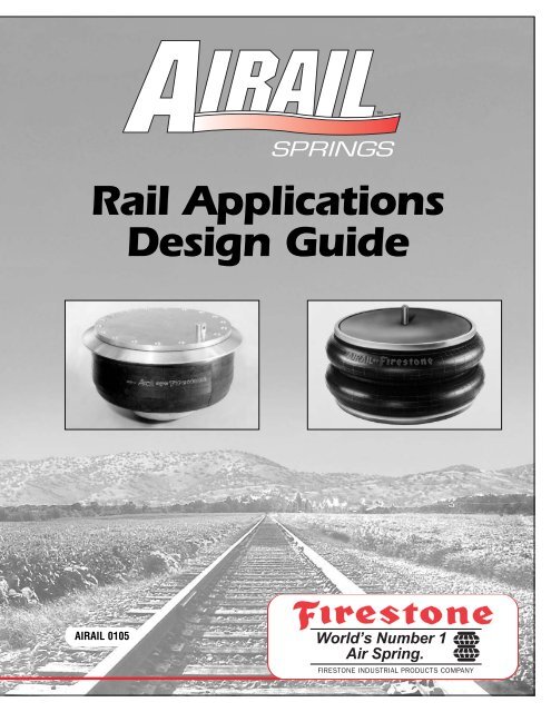
<strong>Rail</strong> <strong>Applications</strong><br />
<strong>Design</strong> <strong>Guide</strong><br />
AIRAIL 0105
<strong>Rail</strong> <strong>Applications</strong><br />
<strong>Design</strong> <strong>Guide</strong><br />
TABLE OF CONTENTS<br />
History . . . . . . . . . . . . . . . . . . . . . . . . . . . . . . . . . . . . . . . . . . . . . . .2<br />
Advantages . . . . . . . . . . . . . . . . . . . . . . . . . . . . . . . . . . . . . . . . . . .3<br />
Terms – Air Springs & Suspensions . . . . . . . . . . . . . . . . . . . . . . . .4<br />
Construction Of Air Springs . . . . . . . . . . . . . . . . . . . . . . . . . . . . . . .6<br />
Styles of Air Springs . . . . . . . . . . . . . . . . . . . . . . . . . . . . . . . . . . . .7<br />
Bead Rings . . . . . . . . . . . . . . . . . . . . . . . . . . . . . . . . . . . . . . . . . .10<br />
How To Use The Product Data Sheets . . . . . . . . . . . . . . . . . . . . .11<br />
Basic Principles (Derivation Of Formulas) . . . . . . . . . . . . . . . . . .17<br />
Technical Data Sheets . . . . . . . . . . . . . . . . . . . . . . . . . . . . . . . . .21<br />
PLEASE NOTE<br />
The information contained in this publication is intended to provide<br />
a general guide to the characteristics and applications of these<br />
products. The material, herein, was developed through engineering<br />
design and development, testing and actual applications and is<br />
believed to be reliable and accurate.<br />
However, <strong>Firestone</strong> makes no warranty, express or implied, of this<br />
information. Anyone making use of this material does so at his own<br />
risk and assumes all liability resulting from such use. It is<br />
suggested that competent professional assistance be employed for<br />
specific applications.
HISTORY<br />
In the early 1930’s, the <strong>Firestone</strong> Tire and Rubber<br />
Company began experiments to develop the potential<br />
of pneumatic springs. In 1938, the country’s largest<br />
manufacturer of motor coaches became interested in<br />
using air springs on a new design bus they were<br />
developing. Working with <strong>Firestone</strong> engineers, the first<br />
buses were tested in 1944 and the inherent ride<br />
superiority of air suspensions was clearly documented.<br />
In the late 1940’s, <strong>Firestone</strong> engineers, encouraged<br />
by the success of the bus application, turned their<br />
attention to the passenger rail market. They saw<br />
an opportunity to use an air spring in the secondary<br />
suspension of the rail truck or bogie. Working closely<br />
with rail truck manufacturers, the engineers at<br />
<strong>Firestone</strong> were able to perfect the double convoluted<br />
style of air spring for rail applications; consequently,<br />
this style became the standard for the next<br />
several years.<br />
2<br />
Development continued<br />
into other vehicular applications.<br />
<strong>Firestone</strong> made huge in-roads into the<br />
automotive, heavy truck and trailer markets.<br />
With the invention of the reversible style air spring,<br />
significant improvements were made to the<br />
performance of the air springs in these applications.<br />
Eventually the passenger rail car manufacturers<br />
desired the benefits of the reversible style air spring as<br />
well. Continuing in the spirit of joint development,<br />
<strong>Firestone</strong> worked with rail truck engineers to perfect<br />
and finalize a reversible style air spring system for<br />
rail applications.<br />
<strong>Firestone</strong> Industrial Products continues to supply and<br />
develop convoluted and reversible style air springs to<br />
passenger rail markets all over the world.
Passenger Comfort<br />
Suspension systems designed with Airail springs<br />
provide a uniformly smooth ride for passenger<br />
comfort. The rail car is cushioned by air springs<br />
from the jolts and vibration experienced by the rail<br />
truck. By incorporating an auxiliary air reservoir, the<br />
frequency and spring rate characteristics of the air<br />
spring can be modified to the exact specifications of<br />
the suspension designer. Utilizing <strong>Firestone</strong>’s<br />
extensive computer modeling programs, the effect of<br />
orifice damping can be determined for controlled<br />
shock absorption.<br />
3<br />
ADVANTAGES<br />
Constant Floor Height<br />
With the use of a leveling system, the air springs can<br />
be used to keep the car floor at a constant height.<br />
When passengers enter, exit or change positions in<br />
the rail car, the air springs and leveling system are<br />
used to maintain a level floor during operation and<br />
at station platforms to insure passenger safety<br />
and comfort.<br />
Performance Benefits<br />
Due to the overall construction, air springs are<br />
virtually noise free and therefore are able to meet the<br />
demands of rail operators for noise reduction.<br />
Another added benefit is a proven service life.<br />
Airail springs are constructed of highly engineered<br />
materials to reduce the effects of abrasion, heat<br />
build-up and ozone attack, making them<br />
capable of service life up to and<br />
exceeding ten years.
TERMS – AIR SPRINGS & SUSPENSIONS<br />
PRESSURE & PROCESS TERMS<br />
Absolute Pressure. The pressure in a vessel<br />
located in a complete vacuum. Usually determined by<br />
adding 14.7 pounds per square inch (psi) to the<br />
gauge pressure. Absolute pressure=gauge<br />
pressure+atmospheric pressure.<br />
Adiabatic Process. All the calculation variables<br />
(volume, pressure, and temperature), change without<br />
any heat transfer (not often a real life situation).<br />
Atmospheric Pressure. The average atmospheric<br />
air pressure measured at sea level. Normally<br />
accepted to be 14.7 pounds per square inch (psi).<br />
Constant Volume With Airflow Process. Volume<br />
and temperature constant, pressure changes. This<br />
condition applies when load is added or removed<br />
from above the air spring over a period of time.<br />
Gauge Pressure. Gas or liquid pressure in a vessel,<br />
which is higher than atmospheric pressure. Usually<br />
measured by a Bourdon tube gauge in pounds per<br />
square inch (psi).<br />
Polytropic Process. All the calculation variables<br />
(volume, pressure, and temperature), change with<br />
heat transfer to the air spring structure. To account for<br />
this, air spring dynamic operation is calculated by the<br />
use of what is known as the polytropic exponent (n).<br />
n=1.38 is the generally accepted value for air springs.<br />
AIR SPRING COMPONENT TERMS<br />
Bead. A part of the flexible member that locks the<br />
cord structure to an inside reinforcing metal ring and<br />
provides a means of sealing the joint between the<br />
flexible member and the adjacent structure.<br />
Bead Plate. A metal plate closing the top end of the<br />
flexible member. It is attached to the flexible member<br />
with a clamp ring. It has studs, blind nuts, brackets, or<br />
pins to facilitate its attachment to the vehicle<br />
structure. A means of supplying air to the assembly is<br />
provided as a separate fitting or in combination with<br />
an attachment stud. Convoluted type springs<br />
incorporate a second bead plate on the bottom to<br />
create an air tight unit and to provide a means of<br />
fastening the unit to the suspension.<br />
4<br />
Bead Ring. A metal ring incorporating a shaped<br />
cross-section that grips the bead of the flexible<br />
member and provides a means of attaching and<br />
sealing the bead to a plate or other structure.<br />
Bead Skirt. A bead ring (see above description) that<br />
has a profile such that it controls the lateral movement<br />
of the spring. A bead skirt is used in reversible style<br />
air springs to give specific lateral spring rates as<br />
required by the car manufacturer.<br />
Bumper. Usually, these are made of rubber, rubber<br />
and fabric, or steel and rubber materials. They are<br />
used to support the vehicle when there is no air in the<br />
air springs, when the vehicle is not in use, or when<br />
there is a system failure on the track. They will also,<br />
to some degree, cushion the shock of very severe<br />
axle force inputs to prevent damage to both the Airail <br />
spring assembly and to the vehicle.<br />
Clamp Ring. A metal hoop that is used to secure a<br />
bead plate to the flexible member.<br />
Flexible Member. The fabric-reinforced rubber<br />
component of the air spring assembly or component<br />
of the air spring.<br />
Piston. A metal component of the air spring assembly<br />
usually placed at the lower end of the flexible member<br />
and used to both support and provide a surface for<br />
the flexible member to roll on. It also provides a<br />
means for attaching the assembly to the mounting<br />
surface. Pistons with tailored contours may be used<br />
to obtain air spring characteristics to meet special<br />
performance requirements.<br />
AIR SPRING TERMS<br />
Assembly. This includes the flexible member, which<br />
may include an upper bead plate, piston, or lower<br />
bead plate with an internal bumper. See illustration on<br />
pages 7-9.<br />
Assembly Volume. The internal working air volume,<br />
exclusive of any external working volume.<br />
Bumper Volume. The space taken up inside the air<br />
spring assembly by the bumper.
Compression Stroke (Jounce). The reduction in<br />
height from the normal design height of the spring as<br />
it cycles in dynamic operation.<br />
<strong>Design</strong> Load. This is the normal maximum static load<br />
the air spring suspension is expected to support. It is<br />
the rated axle load divided by the number of air<br />
springs working with the axle and adjusted according<br />
to any suspension lever arm ratio incorporated.<br />
<strong>Design</strong> Height. The overall height of the air spring as<br />
selected from the characteristics chart design position<br />
range. The air spring selected should provide for<br />
adequate jounce and rebound travel for the proposed<br />
suspension. The design height would be the starting<br />
position for calculating the spring and suspension<br />
dynamic characteristics.<br />
Dynamic Force. The instantaneous supporting force<br />
developed by the air spring during vehicle motion. It is<br />
this constantly changing force that creates the spring<br />
rate, suspension rate, and in combination with the<br />
normal vehicle load on the spring, creates the<br />
suspension system’s natural frequency.<br />
Effective Area. The actual working area<br />
perpendicular to the output force of the spring. It is not<br />
the diameter of the spring. This working area, when<br />
multiplied by the gauge pressure in the spring,<br />
produces the correct output force. Conversely,<br />
dividing the measured output force of the spring by<br />
the measured internal gauge pressure obtains the<br />
correct effective area. In many cases, this is the only<br />
practical way to obtain it.<br />
Extension Stroke (Rebound). The increase in height<br />
from the normal design height of the spring as it<br />
cycles in dynamic operation.<br />
Reservoir Volume. Any working air volume<br />
located externally from the air spring assembly, but<br />
functioning with the spring.<br />
5<br />
SUSPENSION RELATED TERMS<br />
Height Sensor. An electronic device that senses the<br />
position of a suspension or other mechanical device.<br />
The output signal from this device is sent to a control<br />
circuit which then exhausts or adds air to the air<br />
spring through a solenoid valve.<br />
Leveling Valve. A pneumatic valve that senses the<br />
distance between the vehicle frame and the axle via a<br />
mechanical linkage which adds or exhausts air<br />
pressure to maintain a constant vehicle height.<br />
Sprung Mass Natural Frequency. The speed of<br />
vertical oscillations of the suspended vehicle sprung<br />
mass. Can be expressed in cycles per minute (cpm)<br />
or cycles per second (hertz).<br />
Sprung Mass (Weight). That part of the vehicle<br />
structure and cargo that is supported by the<br />
suspension.<br />
Unsprung Mass. That part of the suspension that is<br />
not supported by the spring (e.g., axle wheels, air<br />
spring, etc.).
CONSTRUCTION OF AIR SPRINGS<br />
FLEXIBLE MEMBER CONSTRUCTION<br />
An air spring is a carefully designed rubber and fabric<br />
flexible member which contains a column of<br />
compressed air. The flexible member itself does not<br />
provide force or support load; these functions are<br />
performed by the column of air.<br />
<strong>Firestone</strong> air springs are highly engineered<br />
elastomeric flexible members with specifically<br />
designed metal end closures. The two-ply version is<br />
made up of four layers:<br />
• Inner Liner. An inner liner of calendered rubber.<br />
• First Ply. One ply of fabric-reinforced rubber with<br />
the cords at a specific bias angle.<br />
• Second Ply. A second ply of fabric-reinforced<br />
rubber with the same bias angle laid opposite that<br />
of the first ply.<br />
• Outer Cover. An outer cover of calendered rubber.<br />
6<br />
Outer Cover<br />
Second Ply<br />
First Ply<br />
Inner Liner<br />
Although the two-ply air spring is available, most<br />
<strong>Firestone</strong> air springs for rail applications are built with<br />
four-ply rated construction.<br />
Each air spring’s flexible member is identified by a<br />
style number, which is molded-in during the curing<br />
(vulcanization) process. Examples would be 29, 218,<br />
1T60, etc. This identifies only the rubber/fabric flexible<br />
member . . . not the complete assembly.
REVERSIBLE STYLE AIR SPRING WITH<br />
BEAD SKIRT<br />
A<br />
B<br />
Bead Plate. A metal component, typically steel,<br />
plated for corrosion resistance, bolted to the bead<br />
skirt to create an airtight assembly that allows for<br />
leak testing before the unit leaves the factory.<br />
Bead Skirt. A metal component, typically<br />
aluminum, plated for corrosion resistance that is<br />
used to attach the flexible member to the bead<br />
plate and also to control the lateral movement of<br />
the spring.<br />
7<br />
STYLES OF AIR SPRINGS<br />
C<br />
D<br />
E<br />
Flexible Member. See page 6 for flexible member<br />
construction information.<br />
Piston. A metal component, typically aluminum,<br />
plated for corrosion resistance whose profile,<br />
along with the bead skirt, can further influence the<br />
vertical and lateral characteristics of the spring<br />
per the designer's requirements.<br />
Bumper. An internal component made of rubber,<br />
rubber and fabric or rubber and steel that is used<br />
to prevent damage to the air spring or rail car<br />
during times when no air is in the system.<br />
A<br />
D<br />
C<br />
E<br />
B
CONVOLUTED AIR SPRINGS –<br />
ROLLED PLATE ASSEMBLIES<br />
Convoluted parts are available with bead rings or<br />
permanently attached plates called “rolled plates.”<br />
Rolled plate assemblies may offer an advantage over<br />
bead ring parts because installation is much easier.<br />
When installing rolled plate parts, a backup plate, as<br />
large in diameter as the bead plate, must be used.<br />
This plate should be a minimum of .50” thick.<br />
The blind nut and air entrance locations of rolled plate<br />
assemblies are available from <strong>Firestone</strong>.<br />
A<br />
B<br />
Air Inlet. 3/4” NPT is standard.<br />
Blind Nut. 1/2”-13 UNC thread x .75” deep.<br />
Studs or pins can be used in place of blind nuts.<br />
D<br />
C<br />
8<br />
C<br />
D<br />
E<br />
F<br />
G<br />
G<br />
Upper Bead Plate. 6-gauge (.194”) carbon steel,<br />
plated for corrosion resistance. Permanently<br />
attached to the flexible member with a clamp ring<br />
(D) to form an airtight assembly. Allows for leak<br />
testing before the assembly leaves the factory.<br />
Clamp Ring. This ring is crimped to the bead<br />
plate to permanently attach it to the flexible<br />
member. It is also plated for rust protection.<br />
Girdle Hoop. Solid type shown, molded into the<br />
flexible member between the convolutions.<br />
Flexible Member. See page 6 for flexible member<br />
construction information.<br />
Lower Bead Plate. Usually the same as the<br />
upper bead plate, except without the air inlet.<br />
A B<br />
D<br />
E<br />
F
CONVOLUTED AIR SPRINGS –<br />
BEAD RING ASSEMBLIES<br />
A<br />
B<br />
C<br />
D<br />
E<br />
Mounting Plate. Not included. See page 10<br />
for material, machining recommendations and<br />
installation instructions.<br />
Bead Ring Bolt. Some assemblies may include<br />
one of three varieties included with air spring<br />
assemblies. See chart on page 10.<br />
Nuts & Lock Washers. Included with air spring<br />
assembly.<br />
Flexible Member. See page 6 for flexible member<br />
construction information.<br />
Girdle Hoop. Solid type shown, molded into the<br />
flexible member, between the convolutions.<br />
F<br />
9<br />
F<br />
Bead Ring. Aluminum ribbed neck type shown.<br />
May also be of a second stamped steel variety or<br />
made of aluminum (see page 10).<br />
SERVICE ASSEMBLY<br />
The flexible member is available separately as a<br />
replacement on convoluted bead ring assemblies.<br />
Note: No convoluted bead ring assemblies are<br />
shown in the following product data sheets. All<br />
convoluted air springs shown are available in bead<br />
ring assemblies.<br />
C<br />
A<br />
E<br />
B<br />
D
BEAD RINGS<br />
THREE TYPES OF BEAD RINGS<br />
STEEL COUNTERSUNK<br />
BEAD RING<br />
Customer<br />
Supplies Plate<br />
Bolt<br />
Length<br />
Effective<br />
Length<br />
Standard Bolt Length (in)<br />
15 ⁄8<br />
Standard Effective Length (in)<br />
1.22<br />
Standard Order Number (bolt only)<br />
WC1-358-3625<br />
Thread<br />
5<br />
/16-24UNF<br />
Tightening Torque (ft-lb)<br />
17 to 22<br />
INSTALLING AIR SPRINGS WITH BEAD RINGS<br />
When using bead rings, you will need to fabricate your<br />
own mounting plates. Hot or cold rolled steel provides<br />
satisfactory mounting surfaces with finishes of<br />
250 micro inches, if machined in a circular fashion, or<br />
32 micro inches when ground (side-to-side). The<br />
thickness of mounting plates depends upon the<br />
application. The plates must be strong enough and<br />
backed by structural members to prevent bowing of<br />
the plates when subjected to the forces or loads<br />
involved. The flexible member provides its own seal,<br />
so “O” rings or other sealants are not required.<br />
INSTALLATION<br />
Follow this technique for assembling a bead ring style<br />
flexible member to the mounting plate:<br />
1. Insert the bolts into the bead ring, which has<br />
already been attached to the flexible member.<br />
2. Slip all of the bolts, which protrude through the<br />
bead ring, into the mating holes of the mounting<br />
plate and attach the lock washers and nuts. Finger<br />
ALUMINUM RIBBED NECK<br />
BEAD RING<br />
Customer<br />
Supplies Plate<br />
10<br />
Bolt<br />
Length<br />
Effective<br />
Length<br />
Standard Bolt Length (in)<br />
17 ⁄8<br />
Standard Effective Length (in)<br />
1.28<br />
Standard Order Number (bolt only)<br />
WC1-358-3620<br />
Thread<br />
3<br />
/8-24UNF<br />
Tightening Torque (ft-lb)<br />
28 to 32<br />
ALUMINUM SOCKET HEAD<br />
BEAD RING*<br />
Customer<br />
Supplies Plate<br />
Optional Shorter Length<br />
Ribbed Neck Bolt<br />
Use 1/4”<br />
Cap Screws,<br />
(Not Included)<br />
Standard Bolt Length (in)<br />
11 ⁄4<br />
Optional Effective Length (in)<br />
0.66<br />
Optional Order Number (bolt only)<br />
WC1-358-3618<br />
Thread<br />
3<br />
/8-24UNF<br />
Tightening Torque (ft-lb)<br />
28 to 32<br />
tighten all nuts to produce a uniform gap between<br />
the bead ring and mounting plate all the way<br />
around. The bolts will be pulled into place by<br />
the action of tightening the nuts. When using<br />
aluminum bead rings, it may be necessary to<br />
lightly tap the ribbed neck bolts with a small<br />
hammer to engage the splined portion into the<br />
bead ring.<br />
3. Make certain that the flexible member bead is<br />
properly seated under the bead ring. Please note<br />
that uniform successive tightening of the nuts is<br />
important to seat the rubber bead properly to the<br />
mounting plate around its full circumference.<br />
4. Tighten all nuts one turn each, moving around the<br />
circle until continuous contact is made between<br />
the bead ring and mounting plate.<br />
5. Torque all nuts to the torque specifications shown<br />
in the chart above, going at least two complete<br />
turns around the bolt circle.<br />
Note: Consult <strong>Firestone</strong> for proper selection of bead<br />
ring type.
INTRODUCTION<br />
This section is a guide to using the Product Data<br />
Sheets which <strong>Firestone</strong> Industrial Products Company<br />
publishes for Airail air springs.<br />
These sheets show the mounting configuration,<br />
physical limitations and technical characteristics<br />
of the air spring. With this information, the suspension<br />
designer can accurately calculate the overall<br />
performance of an air suspension system.<br />
The Product Data Sheets can also serve as a guide<br />
for selecting a particular air spring for a new<br />
suspension system.<br />
A<br />
B<br />
C<br />
D<br />
E<br />
F<br />
G<br />
H<br />
I<br />
The part description is shown in the<br />
upper right corner.<br />
Bead plate diameter.<br />
Bead plate mounting arrangement.<br />
Bead skirt diameter, or on convoluted<br />
air spring data sheets, the maximum<br />
rubber part diameter at 100 psig and<br />
minimum height.<br />
Piston body diameter.<br />
Bumper.<br />
“B” dimension. The distance from the<br />
piston base mounting surface to<br />
the bottom of the loop of the<br />
flexible member.<br />
The assembly Order Number,<br />
W01-358-9456.<br />
Approximate weight of the assembly.<br />
HOW TO USE THE PRODUCT DATA SHEETS<br />
G<br />
F<br />
B<br />
B-DIM.<br />
H<br />
11<br />
1.38<br />
18.32<br />
27.44<br />
21.46<br />
5.94<br />
3.34<br />
15.91<br />
16.77<br />
E<br />
WO1-358-9456 SHOWN<br />
(WT 245 LBS)<br />
A<br />
D<br />
I<br />
C<br />
HEIGHT
STATIC DATA CHART<br />
This chart is referred to as the Static Load Deflection<br />
Curve for an air spring. The following parameters are<br />
displayed:<br />
A<br />
B<br />
C<br />
D<br />
E<br />
F<br />
G<br />
Recommended <strong>Design</strong> Position Static<br />
Pressure. The recommended static operating<br />
pressure range is shown at the top of the chart.<br />
This is 20 to 100 psig for most air springs. The<br />
minimum pressure is required to prevent internal<br />
damage to the air spring.<br />
The Load is given on the right-hand axis vs. the<br />
air spring Height along the bottom axis. The<br />
internal Volume is also given along the left-hand<br />
axis vs. the Height.<br />
The Bumper Contact shows the compressed<br />
height of the air spring when the bead plate<br />
comes in contact with the internal bumper as<br />
shown on the air spring drawing.<br />
The Minimum Height shows the lowest<br />
compressed position of the air spring before<br />
internal contact. In many instances, an external<br />
positive stop may be required to prevent internal<br />
damage to the air spring.<br />
The Maximum Rebound Height is the maximum<br />
extended position of the air spring before the<br />
flexible member is put in tension. Some means of<br />
preventing the suspension extending the air<br />
spring past this height must be provided to<br />
prevent damage to the air spring. Shock<br />
absorbers are typically used, however chains,<br />
straps, and positive stops may also be used.<br />
The <strong>Design</strong> Position Range shows the<br />
recommended operating range of static heights.<br />
This range is 8 to 10 inches for the 1T52-420, as<br />
shown on the chart. Use outside range may be<br />
possible, however, <strong>Firestone</strong> should be consulted.<br />
The Constant Pressure Curve is the Load trace<br />
obtained as the part is compressed from the<br />
maximum height to the minimum height while<br />
maintaining a regulated constant pressure in the<br />
part. A series of constant pressure curves, 20 psig<br />
through 120 psig are shown at 20 psi increments.<br />
The 120 psig curve is shown for reference only, as<br />
most parts are limited to static design pressure<br />
of 100 psig.<br />
(continued on page 13)<br />
12<br />
F<br />
G<br />
B<br />
H<br />
E<br />
V O L U M E C U I N X 1 0 0<br />
60<br />
40<br />
20<br />
Maximum<br />
Rebound<br />
Height<br />
100 Psig<br />
V olume<br />
ST A TIC DA T A<br />
Recommended <strong>Design</strong> Position<br />
Static Pressure 20-100 Psig<br />
DESIGN<br />
POSITION<br />
RANGE<br />
HEIGHT IN .<br />
(Data without bumper)<br />
120 Psig<br />
100 Psig<br />
80 Psig<br />
60 Psig<br />
40 Psig<br />
20 Psig<br />
6773<br />
0<br />
(7.85)<br />
Bumper Contact<br />
Height<br />
Minimum<br />
Height<br />
0<br />
12 11 10 9 8 7<br />
60<br />
40<br />
20<br />
LOAD LBS X 100<br />
A<br />
B<br />
I<br />
C<br />
D
STATIC DATA CHART (continued)<br />
H<br />
I<br />
The Volume Curve is a plot of the data points<br />
obtained by measuring the volume of exhausted<br />
liquid as the part is compressed from maximum to<br />
minimum height while maintaining a regulated<br />
pressure of 100 psig in the air spring. (This is the<br />
volume without a bumper).<br />
The number, 6773, is the Test Request<br />
Reference Number.<br />
13<br />
100 PSIG DATA TABLE<br />
This is a table of static data on the 100 psig constant<br />
pressure curve with loads, volumes and “B”<br />
dimensions shown.<br />
The Static Data Table contains the following information:<br />
• Height at each .50" increment.<br />
• Load at each .50" increment.<br />
• Volume at each .50" increment.<br />
• “B” dimension (the distance from the piston base<br />
mounting surface to the bottom of the loop of the<br />
flexible member) at each .50" increment.<br />
All data is calculated without a bumper.<br />
100 Psig Data<br />
Height (in) Load (lbs)<br />
Volume<br />
(in3 )<br />
B Dim. (in)<br />
17.00 30715 4263.80<br />
16.50 31183 4109.72 7.32<br />
16.00 31666 3951.81 7.04<br />
15.50 32062 3790.89 6.79<br />
15.00 32317 3627.78 6.46<br />
14.50 32412 3463.29 6.15<br />
14.00 32345 3298.24 5.80<br />
13.50 32122 3133.45 5.48<br />
13.00 31753 2969.72 5.12<br />
12.50 31243 2807.89 4.71<br />
12.00 30600 2648.76 4.38<br />
11.50 29834 2493.14 4.00<br />
11.00 28965 2341.86 3.62<br />
10.50 28036 2195.73 3.25<br />
10.00 27124 2055.56 2.90<br />
5773
DYNAMIC CHARACTERISTICS TABLE<br />
The Dynamic Characteristics Table consists of the<br />
following calculated characteristics:<br />
• Data for three design heights within the design<br />
position range: minimum, midrange and maximum.<br />
• Four loads at each design height.<br />
• Pressure, Rate, and Frequency for each design<br />
height and load condition.<br />
All data is calculated without a bumper.<br />
<strong>Design</strong><br />
Height<br />
(in)<br />
Dynamic Characteristic at Various <strong>Design</strong> Heights<br />
Load (lbs) Pressure<br />
(psig)<br />
Rate<br />
(lbs/in)<br />
Natural Frequency<br />
(CPM) (Hz)<br />
8.00 14000 38.0 3323 91.6 1.53<br />
8.00 22000 59.8 4584 85.8 1.43<br />
8.00 30000 81.5 5844 83.0 1.38<br />
8.00 38000 103.2 7104 91.3 1.35<br />
9.00 14000 36.8 3402 92.7 1.54<br />
9.00 22000 57.8 4751 87.4 1.46<br />
9.00 30000 78.8 6101 84.8 1.41<br />
9.00 38000 99.9 7450 83.2 1.39<br />
10.00 14000 36.6 3315 91.5 1.52<br />
10.00 22000 57.5 4672 86.6 1.44<br />
10.00 30000 78.4 6028 84.3 1.40<br />
10.00 38000 99.3 7385 82.9 1.38<br />
5773<br />
14<br />
RATE AND FREQUENCY WITH<br />
INCREASING VOLUME<br />
This chart shows the change in the air spring's<br />
vertical rate and natural frequency with the addition of<br />
external reservoir volume.<br />
The data is calculated at a mid-range design height<br />
and at 100 psig internal volume.<br />
All data is calculated without a bumper.<br />
Reservoir<br />
Volume (in 3 )<br />
Rate and Frequency with Increasing Volume<br />
at 9" <strong>Design</strong> Height and 100 psi<br />
Vertical Rate<br />
(lbs/in)<br />
Vertical Natural Frequency<br />
(CPM) (Hz)<br />
0 7480.00 83.4 1.39<br />
1500 4639.65 65.7 1.09<br />
3000 3275.75 55.2 0.92<br />
4500 2470.51 47.9 0.80<br />
6000 1938.87 42.4 0.71<br />
7500 1561.56 38.1 0.63<br />
9000 1279.90 34.5 0.57<br />
10500 1061.59 31.4 0.52<br />
12000 887.40 28.7 0.48<br />
13500 745.20 26.3 0.44<br />
15000 626.92 24.1 0.40<br />
5773
DYNAMIC LOAD VS. DEFLECTION CHART<br />
This chart shows the variation in Dynamic Load vs.<br />
Deflection for the 1T52-420.<br />
The curves are obtained by extending (rebound) or<br />
compressing (jounce) the air spring with captured air.<br />
The starting point for each curve is at a design height<br />
of 9 inches, which is the mid-design position, and<br />
starting pressures of 20, 40, 60, 80 and 100 psig.<br />
As you can see on the DYNAMIC LOAD axis, the<br />
load is approximately 38,000 lb at the design height<br />
of 9 inches and pressure of 100 psig.<br />
When the air spring is compressed one inch to an<br />
8 inch height, the load increases to approximately<br />
46,000 lb, (with a corresponding increase in pressure<br />
to 125 psig).<br />
When the air spring is extended one inch to a 10 inch<br />
height, the load is reduced to 31,000 lb, (with a<br />
corresponding reduction in pressure to 78 psig).<br />
DYNAMIC LOAD LBS x 1000<br />
48<br />
40<br />
32<br />
24<br />
16<br />
8<br />
Dynamic Load vs. Deflectio n<br />
DESIGN<br />
HEIGHT<br />
100 Psi g<br />
80 Psi g<br />
60 Psi g<br />
40 Psi g<br />
20 Psi g<br />
6773<br />
0<br />
10 9 8<br />
R EBOUND H EIGHT IN .<br />
JOUNCE<br />
15<br />
LATERAL SPRING RATE<br />
This chart shows the calculated lateral spring rate of<br />
the air spring.<br />
The lateral rates are calculated at a mid-range design<br />
height and an input frequency of 0.1 Hz.<br />
Pressure<br />
(psi)<br />
Lateral Spring Rate<br />
at 9" <strong>Design</strong> Height & 0.1 Hz frequency<br />
Rate (lbs/in)<br />
at ± 0.5 in<br />
Rate (lbs/in)<br />
at ± 1.0 in<br />
Rate (lbs/in)<br />
at ± 1.5 in<br />
60 2125 1450 1192<br />
80 2250 1600 1317<br />
100 2500 1737 1400<br />
6945
FASTENER TIGHTENING SPECIFICATIONS OPERATIONAL CAUTIONS<br />
Description Size Torque (ft-lb)<br />
• Bead ring nuts 5 /16-24 17-22<br />
on bolts<br />
• Bead ring bolts 3 /8-24 28-32<br />
and nuts<br />
• Bolts in blind nuts 3 /8-16 15-20<br />
in bead plates<br />
• End of adapter 3 /8-16 15-20<br />
studs in blind nut<br />
• Nut on end of 1 /2-13 25-30<br />
adapter studs<br />
• Studs on 1 /2-13 or 25-30<br />
bead plates<br />
or blind nuts<br />
1 /2-20<br />
• Bolt to attach 1 /2-13 25-30<br />
piston base to<br />
lower mounting<br />
surface<br />
• Nut on air 3 /4-16 40-45<br />
entrance stud<br />
• NPT air supply 1 /4 & up 17-22<br />
fitting<br />
• Nut on end closure 3 /4-10 45-50<br />
lower mounting<br />
16<br />
Air spring failure can be caused by a variety of<br />
situations, including internal or external rubbing,<br />
excessive heat and overextension.<br />
TEMPERATURE RANGE<br />
The normal ambient operating temperature range for<br />
standard vehicular air springs is -65 O F to +135 O F.<br />
BUMPERS<br />
In general, bumpers are used to support the vehicle<br />
weight to prevent damage to the flexible member<br />
during times when no air is in the system. In<br />
applications that require frequent bumper contact,<br />
consult <strong>Firestone</strong>. There are a variety of bumpers<br />
available for use in Airail springs. <strong>Firestone</strong> has<br />
developed a line of progressive springs under the<br />
trade name Marsh Mellow . These springs have been<br />
used extensively in rail springs because of their<br />
unique performance characteristics. Due to the Marsh<br />
Mellow spring’s greater deflection capabilities and<br />
load carrying influences of the fabric reinforcement, it<br />
can carry a greater load when compared to an all<br />
rubber part of the same modulus and dimensions.<br />
<strong>Firestone</strong> also offers molded rubber bumpers that<br />
are manufactured by <strong>Firestone</strong> along with the<br />
Marsh Mellow springs, if required bumpers can be<br />
purchased from outside vendors for use inside the<br />
Airail springs.
INTRODUCTION<br />
The fundamental concept of an air spring is a mass of<br />
air under pressure in a vessel arranged so that the<br />
pressure exerts a force. The amount of static force<br />
developed by the air spring is dependent on the<br />
internal pressure and the size and configuration of the<br />
vessel. The vessel is defined in this manual as the<br />
Airail spring by <strong>Firestone</strong> or air spring.<br />
Dynamic force is the result of internal pressure<br />
changes and air spring effective area changes<br />
as height decreases (compresses) or increases<br />
(extends).<br />
The amount of pressure change for a stroke depends<br />
on volume change compared to total volume at<br />
equilibrium position. For the convoluted type, effective<br />
area change for a stroke depends on where in the<br />
total travel range the motion takes place. For the<br />
reversible sleeve type, the shape of the piston, size of<br />
the piston related to the flexible member diameter,<br />
and cord angle built into the flexible member all have<br />
an influence on effective area.<br />
The effective area can be arrived at by taking the<br />
longitudinal static force developed at a specified<br />
assembly height and dividing this force by the internal<br />
pressure (psig) existing in the air spring at that<br />
height. This method is used to develop the static<br />
effective areas used in dynamic rate and frequency<br />
calculations.<br />
EFFECTIVE AREA<br />
Effective area is the load carrying area of the air<br />
spring. Its diameter is determined by the distance<br />
between the centers of the radius of curvature of the<br />
flexible member loop. The loop always approximates<br />
a circle because the internal air pressure is acting<br />
uniformly in all directions, so that only the area inside<br />
the centers is vertically effective. For a convoluted air<br />
spring, the effective area increases in compression<br />
and decreases on extension. For a reversible sleeve<br />
air spring, the effective area is constant while<br />
operating on the straight side of the piston, increases<br />
when working on the flare of the piston in<br />
compression, and decreases when the rubber part<br />
lifts off the piston in extension.<br />
17<br />
When a vehicle having air springs in its suspension is<br />
at rest, and then load is added or removed, the height<br />
control valve operates to add or remove sufficient air<br />
in the air spring to maintain the set air spring overall<br />
height. This then increases or decreases the pressure<br />
in the air spring the amount needed to provide<br />
the required lifting force to match the current<br />
downward force created by the new load condition,<br />
and equilibrium is again reached.<br />
Loop<br />
BASIC PRINCIPLES<br />
Effective<br />
Diameter<br />
Effective<br />
Diameter<br />
Convoluted<br />
Air Spring<br />
Change in<br />
Effective Diameter<br />
Effective<br />
Diameter<br />
Effective<br />
Diameter<br />
Reversible Sleeve<br />
Air Spring<br />
Change in<br />
Effective Diameter<br />
Load<br />
Effective Area = ––––––––<br />
Pressure<br />
Load (supporting force) = Pressure x Area<br />
Loop
SPECIAL CHANGES OF STATE<br />
FOR IDEAL GASES<br />
Non-flow process, specific heats assumed constant.<br />
Subscripts 1 and 2 refer to the initial and final states,<br />
respectively.<br />
1<br />
2<br />
3<br />
4<br />
P = Absolute Pressure<br />
T = Absolute Temperature<br />
V = Total Volume<br />
Constant Volume (Isochoric)<br />
P2 P1 This is an unattainable process due to the nature<br />
of the flexible member; however, at static<br />
conditions, the change in pressure may be<br />
calculated for a change in temperature.<br />
Constant Pressure (Isobaric)<br />
V2 V1 Dynamically, the only way to maintain constant<br />
pressure is in combination with infinite volume<br />
and is generally not useful.<br />
Constant Temperature (Isothermal)<br />
This requires very slow movements not normally<br />
applicable to air spring operation.<br />
Reversible Adiabatic (Isentropic)<br />
P 1V 1 k = P 2V 2 k<br />
And:<br />
T2 T1 ––– = –––<br />
T2 T1 ––– = –––<br />
P2 P1 T 2<br />
V2 V1 ––– = –––<br />
V k-1<br />
2 P (k-1)<br />
2 k ( ) ( )<br />
––– = ––– = –––<br />
T1 V1 P1 This is defined as a process with no heat<br />
transferred to or from the working fluid. This is a<br />
18<br />
5<br />
6<br />
theoretical process not attainable with pneumatic<br />
springs, however, for rapid deflections, it is<br />
closely approached. k=1.404 for air.<br />
Polytropic<br />
PV n = Constant<br />
This process usually represents actual expansion<br />
and compression curves for pressures up to a few<br />
hundred pounds. Assuming the specific heat of<br />
the gas is constant, "n" may be changed for<br />
special cases of the polytropic process.<br />
Thus for:<br />
n = 1, PV = Const. (Isothermal)<br />
n = k, PV k = Const. (Isentropic)<br />
n = 0, P = Const. (Constant Pressure)<br />
n = ∞, V = Const. (Constant Volume)<br />
The principal formulas for air compression up to a<br />
few hundred pounds pressure where 1
DYNAMIC AIR SPRING RATE<br />
Rate is the slope of the tangent at the equilibrium<br />
position. For small increments of deflection, rate<br />
equals the load change per unit deflection.<br />
(The slope of the chord line through L c and L e is<br />
parallel to the tangent at L for small deflections.)<br />
1<br />
2<br />
3<br />
Load<br />
Load Deflection Curve<br />
K = (L c – L e) / (Δh c + Δh e)<br />
Where:<br />
K = Rate (Load per unit deflection)<br />
L c = Load at compression travel<br />
L e = Load at extension travel<br />
Δh c = Height change, compression<br />
Δh e = Height change, extension<br />
L c = P gc(A c)<br />
L e = P ge(A e)<br />
Where:<br />
L e<br />
Equilibrium<br />
Δh e<br />
Pgc = Gauge Pressure at Lc Pge = Gauge Pressure at Le Ac = Effective area at Lc Ae = Effective area at Le substituting 2 in 1 and setting Δhc=Δhe=.5 inch<br />
K = P gc(A c) – P ge(A e)<br />
L<br />
Position<br />
Δh c<br />
L c<br />
Extension Compression<br />
Deflection<br />
ΔL c<br />
ΔL e<br />
L e<br />
L<br />
L c<br />
19<br />
4<br />
5<br />
6<br />
7<br />
P gc = P ac – 14.7<br />
P ge = P ae – 14.7<br />
Where:<br />
P ac = Absolute Pressure at L c<br />
P ae = Absolute Pressure at L e<br />
14.7 = Atmospheric Pressure in pounds per in 2<br />
Now using the polytropic gas law and n=1.38<br />
Where:<br />
( )<br />
V1 Vc P ac = P a1 –––<br />
( )<br />
V1 Ve P ae = P a1 –––<br />
P a1 = Absolute Pressure at equilibrium position<br />
V 1 = Volume at equilibrium position<br />
V c = Volume at L c<br />
V e = Volume at L e<br />
substituting 5 in 4<br />
( )<br />
V1 Vc substituting 6 in 3<br />
2. 3 K = Pgc(Ac) – Pge(Ae) V 1.38<br />
1<br />
V 1.38<br />
1<br />
K = Pa1 ( ––– ) –14.7 Ac– Pa1 ( ––– ) –14.7 Ae V c<br />
1.38<br />
1.38<br />
1.38<br />
P gc = P a1 ––– –14.7<br />
( )<br />
V1 Ve 1.38<br />
P ge = P a1 ––– –14.7<br />
Then, grouping terms, this becomes the general rate<br />
formula for air springs.<br />
8<br />
V 1.38<br />
1 V 1.38<br />
1 ( –––<br />
V ) ( –––<br />
c V ) e<br />
K = P a1 A c –A e –14.7(A c–A e)<br />
V e
NATURAL FREQUENCY<br />
Since the air spring has a variable rate and essentially<br />
a constant frequency, it is helpful to calculate the<br />
natural frequency when evaluating characteristics.<br />
When considering a single-degree-of-freedom system<br />
(undamped), the classical definition of frequency is<br />
as follows:<br />
Note: The period of free vibration (which is the reciprocal of<br />
frequency) is the same as the period of a mathematical<br />
pendulum, the length of which is equal to the static<br />
deflection of the spring under the action of load W.<br />
Where:<br />
Then:<br />
Also:<br />
ω K<br />
f = ––– and ω<br />
2π m<br />
2 = –––<br />
f = Frequency, cycles per second<br />
ω = Circular frequency, radians per second<br />
K = Rate, pounds per inch<br />
m = Mass, pound seconds 2 per inch<br />
Where:<br />
K<br />
— m<br />
1 K<br />
f = ––– = ––– ––<br />
2π 2π m<br />
W<br />
m = –––<br />
g<br />
W = Weight, pounds<br />
g = Acceleration of gravity, 386 inches<br />
per second 2<br />
Substituting:<br />
1 Kg 386 K<br />
f = ––– ––– = –––– –– cps<br />
2π W 2πW 60 386 K<br />
f = ––––––– –– cpm<br />
2π W<br />
This is normally rounded to:<br />
K<br />
f = 188 –– cpm<br />
W<br />
20<br />
Where:<br />
K = Rate<br />
W = Weight (load)<br />
Also since:<br />
W<br />
––– = d<br />
K e (effective deflection)<br />
188<br />
f = ––– cpm<br />
de Effective deflection (d e) has no physical significance,<br />
however, it has mathematical meaning. It is defined<br />
as load divided by rate and is graphically<br />
explained below.<br />
Load<br />
Variable Rate Spring<br />
d<br />
Load<br />
e = –––––<br />
Rate<br />
Load = Rate x d e<br />
Note: For a constant rate spring, d e and the deflection from<br />
free height are equal.<br />
SUMMARY OF IMPORTANT FORMULAS<br />
Polytropic Gas Law<br />
n n<br />
P1V1 = P2V2 Dynamic Air Spring Rate<br />
Natural Frequency<br />
d e<br />
Deflection<br />
Load Deflection<br />
Curve<br />
Tangent<br />
V 1.38<br />
1 V 1.38<br />
1 ( –––<br />
V ) ( –––<br />
c V ) e<br />
K = P a1 A c –A e –14.7(A c–A e)<br />
K 188<br />
f = 188 –– = ––– cpm<br />
W de
TECHNICAL<br />
DATA SHEETS<br />
21
205<br />
VOLUME in 3 X 100<br />
16<br />
12<br />
8<br />
4<br />
100 Psig<br />
Volume<br />
0 0<br />
13 11 9 7 5 3<br />
Maximum Rebound<br />
Height<br />
STATIC DATA<br />
Recommended <strong>Design</strong> Position<br />
Static Pressure 20-100 Psig<br />
DESIGN<br />
POSITION<br />
RANGE<br />
HEIGHT IN.<br />
(Data without bumper)<br />
120 Psig<br />
100 Psig<br />
80 Psig<br />
60 Psig<br />
40 Psig<br />
20 Psig<br />
16<br />
12<br />
8<br />
4<br />
Minimum<br />
Height<br />
22<br />
LOAD LBS X 1000<br />
5/8 UNC 3/4 DEEP<br />
15.10 MAX OD<br />
11.31<br />
3.00<br />
4.50<br />
WO1-764-7205 SHOWN<br />
(WT 21.5 LBS)<br />
100 Psig Data<br />
Height (in) Load (lbs) Volume (in 3 )<br />
12.50 2222 1304.47<br />
12.00 3571 1279.87<br />
11.50 4790 1250.87<br />
11.00 5879 1217.88<br />
10.50 6840 1181.08<br />
10.00 7684 1140.69<br />
9.50 8422 1096.99<br />
9.00 9067 1050.09<br />
8.50 9636 1000.30<br />
8.00 10142 947.81<br />
7.50 10602 892.91<br />
7.00 11028 835.72<br />
6.50 11430 776.62<br />
6.00 11815 715.73<br />
5.50 12183 653.33<br />
5.00 12531 589.74<br />
4.50 12847 524.95<br />
4.00 13113 459.35<br />
3.50 13300 393.26<br />
11.31<br />
9914<br />
HEIGHT
<strong>Design</strong><br />
Height<br />
(in)<br />
Dynamic Characteristic at Various <strong>Design</strong> Heights<br />
Load (lbs) Pressure<br />
(psig)<br />
Rate<br />
(lbs/in)<br />
Natural Frequency<br />
(CPM) (Hz)<br />
7.00 4000 36.3 1393 110.9 1.85<br />
7.00 6000 54.4 1931 106.7 1.78<br />
7.00 8000 72.5 2470 104.5 1.74<br />
7.00 10000 90.7 3009 103.1 1.72<br />
8.00 4000 39.4 1248 105.0 1.75<br />
8.00 6000 59.2 1754 101.6 1.69<br />
8.00 8000 78.9 2260 99.9 1.67<br />
8.00 10000 98.6 2766 98.9 1.65<br />
9.00 4000 44.1 1218 103.8 1.73<br />
9.00 6000 66.2 1742 101.3 1.69<br />
9.00 8000 88.2 2266 100.1 1.67<br />
9.00 10000 110.3 2790 99.3 1.66<br />
Reservoir<br />
Volume (in 3 )<br />
Rate and Frequency with Increasing Volume<br />
at 8.0" <strong>Design</strong> Height and 100 psi<br />
Vertical Rate<br />
(lbs/in)<br />
Vertical Natural Frequency<br />
(CPM) (Hz)<br />
0 2782.73 98.5 1.64<br />
500 2162.41 86.8 1.45<br />
1000 1853.65 80.4 1.34<br />
1500 1671.64 76.3 1.27<br />
2000 1551.60 73.5 1.23<br />
2500 1466.47 71.5 1.19<br />
3000 1402.96 69.9 1.17<br />
3500 1353.75 68.7 1.14<br />
4000 1314.51 67.7 1.13<br />
4500 1282.48 66.9 1.11<br />
5000 1255.84 66.2 1.10<br />
9914<br />
9914<br />
23<br />
DYNAMIC LOAD LBS x 1000<br />
20<br />
16<br />
12<br />
8<br />
4<br />
0<br />
10.0<br />
Pressure<br />
(psi)<br />
Dynamic Load vs. Deflection<br />
DESIGN<br />
HEIGHT<br />
8.0<br />
HEIGHT IN.<br />
100 Psig<br />
80 Psig<br />
60 Psig<br />
40 Psig<br />
20 Psig<br />
Lateral Spring Rate<br />
at 8.0" <strong>Design</strong> Height & 0.1 Hz frequency<br />
Rate (lbs/in)<br />
at ± 0.5 in<br />
Rate (lbs/in)<br />
at ± 1.0 in<br />
205<br />
9914<br />
6.0<br />
Rate (lbs/in)<br />
at ± 1.5 in<br />
20 222 175 153<br />
40 345 260 215<br />
60 390 300 248<br />
80 400 325 267<br />
100 410 330 275<br />
6978
201<br />
VOLUME in 3 X 100<br />
2000<br />
1600<br />
1200<br />
800<br />
400<br />
12<br />
Maximum Rebound<br />
Height<br />
100 Psig<br />
Volume<br />
11<br />
STATIC DATA<br />
Recommended <strong>Design</strong> Position<br />
Static Pressure 20-100 Psig<br />
10<br />
9<br />
DESIGN<br />
POSITION<br />
RANGE<br />
8<br />
7<br />
60 Psig<br />
6<br />
HEIGHT IN.<br />
(Data without bumper)<br />
120 Psig<br />
100 Psig<br />
80 Psig<br />
40 Psig<br />
20 Psig<br />
5<br />
4<br />
5520 5524<br />
25<br />
20<br />
15<br />
LOAD LBS X 1000<br />
10<br />
5<br />
Minimum Height<br />
24<br />
.75<br />
1.62<br />
17.40 MAX OD<br />
13.79<br />
1.62<br />
2.75<br />
1.50<br />
WO1-358-7285 SHOWN<br />
(WT 30.0 LBS)<br />
13.79<br />
100 Psig Data<br />
Height (in) Load (lbs) Volume (in 3 )<br />
12.50 5500 1835.00<br />
12.00 7272 1799.00<br />
11.50 8694 1756.00<br />
11.00 9925 1705.00<br />
10.50 10909 1649.00<br />
10.00 11893 1587.00<br />
9.50 12689 1519.00<br />
9.00 13484 1449.00<br />
8.50 14166 1375.00<br />
8.00 14810 1298.00<br />
7.50 15394 1216.00<br />
7.00 15977 1134.00<br />
6.50 16428 1050.00<br />
6.00 16917 963.00<br />
5.50 17293 874.00<br />
5.00 17727 783.00<br />
4.50 18068 689.00<br />
4.00 18409 596.00<br />
3.50 18712 498.00<br />
HEIGHT<br />
5520
<strong>Design</strong><br />
Height<br />
(in)<br />
Dynamic Characteristic at Various <strong>Design</strong> Heights<br />
Load (lbs) Pressure<br />
(psig)<br />
Rate<br />
(lbs/in)<br />
Natural Frequency<br />
(CPM) (Hz)<br />
7.00 6000 37.5 2035 109.3 1.82<br />
7.00 9000 56.7 2837 105.4 1.76<br />
7.00 12000 74.4 3606 102.9 1.72<br />
7.00 15000 92.8 4341 100.9 1.68<br />
8.00 6000 40.3 1895 105.5 1.76<br />
8.00 9000 60.3 2670 102.2 1.70<br />
8.00 12000 79.8 3367 99.4 1.66<br />
8.00 15000 99.2 4049 97.5 1.63<br />
9.00 6000 44.3 1803 102.8 1.71<br />
9.00 9000 66.0 2484 98.6 1.64<br />
9.00 12000 87.6 3167 96.4 1.61<br />
9.00 15000 108.7 3950 96.3 1.61<br />
Reservoir<br />
Volume (in 3 )<br />
Rate and Frequency with Increasing Volume<br />
at 8.0" <strong>Design</strong> Height and 100 psi<br />
Vertical Rate<br />
(lbs/in)<br />
5520<br />
Vertical Natural Frequency<br />
(CPM) (Hz)<br />
0 4123.00 97.9 1.63<br />
500 3287.00 87.4 1.46<br />
1000 2818.00 80.9 1.35<br />
1500 2518.00 76.5 1.28<br />
2000 2310.00 73.3 1.22<br />
2500 2157.00 70.8 1.18<br />
3000 2039.00 68.8 1.15<br />
3500 1946.00 67.3 1.12<br />
4000 1871.00 65.9 1.10<br />
4500 1809.00 64.8 1.08<br />
5000 1756.00 63.9 1.07<br />
5500 1712.00 63.1 1.05<br />
6000 1673.00 62.4 1.04<br />
6500 1639.00 61.7 1.03<br />
5520<br />
25<br />
DYNAMIC LOAD LBS<br />
30000<br />
25000<br />
20000<br />
15000<br />
10000<br />
5000<br />
0<br />
Dynamic Load vs. Deflection<br />
DESIGN<br />
HEIGHT<br />
10.0 8.0 6.0<br />
Pressure<br />
(psi)<br />
HEIGHT IN.<br />
Lateral Spring Rate<br />
at 8.0" <strong>Design</strong> Height & 0.1 Hz frequency<br />
Rate (lbs/in)<br />
at ± 0.5 in<br />
Rate (lbs/in)<br />
at ± 1.0 in<br />
201<br />
100 Psig<br />
80 Psig<br />
60 Psig<br />
40 Psig<br />
20 Psig<br />
5520<br />
Rate (lbs/in)<br />
at ± 1.5 in<br />
20 375 300 272<br />
40 625 467 396<br />
60 750 606 492<br />
80 825 656 542<br />
100 875 737 608<br />
5519
203<br />
VOLUME in 3 X 100<br />
32<br />
24<br />
16<br />
8<br />
100 Psig<br />
Volume<br />
6969<br />
0<br />
14 12 10 8 6<br />
0<br />
4<br />
Maximum Rebound<br />
Height<br />
STATIC DATA<br />
Recommended <strong>Design</strong> Position<br />
Static Pressure 20-100 Psig<br />
DESIGN<br />
POSITION<br />
RANGE<br />
HEIGHT IN.<br />
(Data without bumper)<br />
120 Psig<br />
100 Psig<br />
80 Psig<br />
60 Psig<br />
40 Psig<br />
20 Psig<br />
32<br />
24<br />
16<br />
8<br />
LOAD LBS X 1000<br />
Minimum Height<br />
26<br />
12.00<br />
1/2-13 UNC-2B x .75 DEEP<br />
4 HOLES EQUALLY SPACED<br />
20.00 MAX OD<br />
16.50<br />
1/2-13 UNC-2B x .75 DEEP<br />
4 HOLES EQUALLY SPACED<br />
45°<br />
WO1-358-7273 SHOWN<br />
(WT 45.2 LBS)<br />
3/4 NPTF<br />
16.50<br />
HEIGHT<br />
100 Psig Data<br />
Height (in) Load (lbs) Volume (in 3 )<br />
13.50 9456 2878.51<br />
13.00 11599 2813.22<br />
12.50 13393 2741.43<br />
12.00 14927 2663.43<br />
11.50 16264 2579.64<br />
11.00 17450 2490.35<br />
10.50 18517 2395.86<br />
10.00 19483 2296.57<br />
9.50 20363 2192.78<br />
9.00 21163 2084.89<br />
8.50 21888 1973.20<br />
8.00 22544 1858.11<br />
7.50 23133 1739.83<br />
7.00 23663 1618.74<br />
6.50 24139 1495.25<br />
6.00 24571 1369.56<br />
5.50 24968 1242.18<br />
5.00 25337 1113.39<br />
4.50 25686 983.50<br />
4.00 26014 852.91<br />
6969
<strong>Design</strong><br />
Height<br />
(in)<br />
Dynamic Characteristic at Various <strong>Design</strong> Heights<br />
Load (lbs) Pressure<br />
(psig)<br />
Rate<br />
(lbs/in)<br />
Natural Frequency<br />
(CPM) (Hz)<br />
8.50 8000 36.5 2297 100.7 1.68<br />
8.50 12000 54.8 3189 96.9 1.62<br />
8.50 17000 77.7 4303 94.6 1.58<br />
8.50 21000 95.9 5195 93.5 1.56<br />
9.00 8000 37.8 2203 98.6 1.64<br />
9.00 12000 56.7 3076 95.2 1.59<br />
9.00 17000 80.3 4168 93.1 1.55<br />
9.00 21000 99.2 5042 92.1 1.54<br />
10.00 8000 41.1 2092 96.1 1.60<br />
10.00 12000 61.6 2962 93.4 1.56<br />
10.00 17000 87.3 4050 91.8 1.53<br />
10.00 21000 107.8 4920 91.0 1.52<br />
Reservoir<br />
Volume (in 3 )<br />
Rate and Frequency with Increasing Volume<br />
at 9.0" <strong>Design</strong> Height and 100 psi<br />
Vertical Rate<br />
(lbs/in)<br />
Vertical Natural Frequency<br />
(CPM) (Hz)<br />
0 5053.23 91.9 1.53<br />
1000 3917.89 80.9 1.35<br />
2000 3329.48 74.6 1.24<br />
3000 2973.49 70.5 1.17<br />
4000 2734.86 67.6 1.13<br />
5000 2563.76 65.4 1.09<br />
6000 2435.06 63.8 1.06<br />
7000 2334.75 62.4 1.04<br />
8000 2254.36 61.4 1.02<br />
9000 2188.49 60.5 1.01<br />
10000 2133.53 59.7 0.99<br />
6969<br />
6969<br />
27<br />
DYNAMIC LOAD LBS x 1000<br />
32<br />
24<br />
16<br />
8<br />
Dynamic Load vs. Deflection<br />
DESIGN<br />
HEIGHT<br />
60 Psig<br />
100 Psig<br />
80 Psig<br />
60 Psig<br />
40 Psig<br />
20 Psig<br />
203<br />
0<br />
6969<br />
10.0 9.0<br />
HEIGHT IN.<br />
8.0<br />
Pressure<br />
(psi)<br />
Lateral Spring Rate<br />
at 9.0" <strong>Design</strong> Height & 0.1 Hz frequency<br />
Rate (lbs/in)<br />
at ± 0.5 in<br />
Rate (lbs/in)<br />
at ± 1.0 in<br />
Rate (lbs/in)<br />
at ± 1.5 in<br />
20 365 287 250<br />
40 500 405 337<br />
60 515 450 388<br />
80 525 481 417<br />
100 587 494 437<br />
6927
218<br />
VOLUME in 3 X 100<br />
32<br />
28<br />
24<br />
20<br />
16<br />
12<br />
8<br />
4<br />
100 Psig<br />
Volume<br />
6217<br />
0<br />
13 11 9 7 5<br />
0<br />
3<br />
Maximum Rebound<br />
Height<br />
STATIC DATA<br />
Recommended <strong>Design</strong> Position<br />
Static Pressure 20-100 Psig<br />
DESIGN<br />
POSITION<br />
RANGE<br />
(7.3)<br />
Bumper Contact Height<br />
HEIGHT IN.<br />
(Data without bumper)<br />
120 Psig<br />
100 Psig<br />
80 Psig<br />
60 Psig<br />
40 Psig<br />
20 Psig<br />
32<br />
28<br />
24<br />
20<br />
16<br />
12<br />
8<br />
4<br />
Minimum Height<br />
28<br />
LOAD LBS X 1000<br />
2.00<br />
16.50<br />
20.00 MAX<br />
12.00<br />
1.0<br />
1.0<br />
16.50<br />
2.50<br />
6.00<br />
1.38<br />
WO1-764-7221 SHOWN<br />
(WT 79.1 LBS)<br />
100 Psig Data<br />
Height (in) Load (lbs) Volume (in 3 )<br />
13.00 8597 2737.23<br />
12.50 10505 2674.53<br />
12.00 12353 2604.54<br />
11.50 14071 2527.75<br />
11.00 15623 2444.56<br />
10.50 16996 2355.36<br />
10.00 18196 2260.67<br />
9.50 19240 2160.78<br />
9.00 20149 2056.29<br />
8.50 20948 1947.51<br />
8.00 21657 1834.82<br />
7.50 22296 1718.73<br />
7.00 22878 1599.74<br />
6.50 23410 1478.05<br />
6.00 23895 1354.36<br />
5.50 24337 1228.88<br />
5.00 24737 1102.09<br />
4.50 25101 974.40<br />
4.00 25448 846.32<br />
3.50 25808 718.33<br />
.75<br />
HEIGHT<br />
6217
<strong>Design</strong><br />
Height<br />
(in)<br />
Dynamic Characteristic at Various <strong>Design</strong> Heights<br />
Load (lbs) Pressure<br />
(psig)<br />
Rate<br />
(lbs/in)<br />
Natural Frequency<br />
(CPM) (Hz)<br />
8.00 8000 36.9 2439 103.8 1.73<br />
8.00 12000 55.4 3382 99.8 1.66<br />
8.00 17000 78.5 4561 97.4 1.62<br />
8.00 21000 97.0 5504 96.2 1.60<br />
8.50 8000 38.2 2328 101.4 1.69<br />
8.50 12000 57.3 3249 97.8 1.63<br />
8.50 17000 81.2 4399 95.6 1.59<br />
8.50 21000 100.2 5320 94.6 1.58<br />
9.00 8000 39.7 2258 99.9 1.66<br />
9.00 12000 59.6 3173 96.7 1.61<br />
9.00 17000 84.4 4318 94.7 1.58<br />
9.00 21000 104.2 5233 93.9 1.56<br />
Reservoir<br />
Volume (in 3 )<br />
Rate and Frequency with Increasing Volume<br />
at 8.5" <strong>Design</strong> Height and 100 psi<br />
Vertical Rate<br />
(lbs/in)<br />
Vertical Natural Frequency<br />
(CPM) (Hz)<br />
0 5275.44 94.3 1.57<br />
1000 4008.49 82.2 1.37<br />
2000 3372.01 75.4 1.26<br />
3000 2993.98 71.1 1.18<br />
4000 2743.49 68.0 1.13<br />
5000 2565.29 65.8 1.10<br />
6000 2432.03 64.1 1.07<br />
7000 2328.60 62.7 1.04<br />
8000 2246.01 61.6 1.03<br />
9000 2178.52 60.6 1.01<br />
10000 2122.34 59.8 1.00<br />
6217<br />
6217<br />
29<br />
DYNAMIC LOAD LBS x 1000<br />
28<br />
24<br />
20<br />
16<br />
12<br />
8<br />
4<br />
Dynamic Load vs. Deflection<br />
DESIGN<br />
HEIGHT<br />
100 Psig<br />
80 Psig<br />
60 Psig<br />
40 Psig<br />
20 Psig<br />
218<br />
0<br />
6217<br />
10.0 9.0 8.0 7.0<br />
HEIGHT IN.<br />
Pressure<br />
(psi)<br />
Lateral Spring Rate<br />
at 8.5" <strong>Design</strong> Height & 0.1 Hz frequency<br />
Rate (lbs/in)<br />
at ± 0.5 in<br />
Rate (lbs/in)<br />
at ± 1.0 in<br />
Rate (lbs/in)<br />
at ± 1.5 in<br />
20 370 300 278<br />
40 600 437 371<br />
60 700 519 419<br />
80 794 600 419<br />
100 800 638 500<br />
6559
29<br />
VOLUME in 3 X 100<br />
40<br />
32<br />
24<br />
16<br />
8<br />
100 Psig<br />
Volume<br />
0 13 11 9 7 5<br />
Maximum Rebound<br />
Height<br />
STATIC DATA<br />
Recommended <strong>Design</strong> Position<br />
Static Pressure 20-100 Psig<br />
DESIGN<br />
POSITION<br />
RANGE<br />
(7.4)<br />
Bumper Contact Height<br />
HEIGHT IN.<br />
(Data without bumper)<br />
120 Psig<br />
100 Psig<br />
80 Psig<br />
40 Psig<br />
20 Psig<br />
60 Psig<br />
5528<br />
(3.5)<br />
Minimum Height<br />
40<br />
32<br />
24<br />
16<br />
8<br />
0<br />
30<br />
LOAD LBS X 1000<br />
5.87<br />
3.50<br />
1.00 NPT<br />
3.37<br />
6.00<br />
12.00<br />
22.40 MAX OD<br />
2.50<br />
19.00<br />
1.00<br />
WO1-764-7229 SHOWN<br />
(WT 86 LBS)<br />
5/8-11 UNC-2A<br />
2 PLACES<br />
100 Psig Data<br />
Height (in) Load (lbs) Volume (in 3 )<br />
13.00 14618 3651.23<br />
12.50 16611 3557.44<br />
12.00 18468 3456.15<br />
11.50 20182 3347.77<br />
11.00 21744 3232.78<br />
10.50 23152 3111.39<br />
10.00 24407 2984.20<br />
9.50 25516 2851.51<br />
9.00 26491 2713.73<br />
8.50 27349 2571.14<br />
8.00 28108 2424.36<br />
7.50 28793 2273.57<br />
7.00 29424 2119.19<br />
6.50 30022 1961.80<br />
6.00 30601 1801.52<br />
5.50 31168 1638.94<br />
5.00 31715 1474.45<br />
4.50 32218 1308.27<br />
4.00 32629 1140.99<br />
3.50 32876 972.90<br />
HEIGHT<br />
5528
<strong>Design</strong><br />
Height<br />
(in)<br />
Dynamic Characteristic at Various <strong>Design</strong> Heights<br />
Load (lbs) Pressure<br />
(psig)<br />
Rate<br />
(lbs/in)<br />
Natural Frequency<br />
(CPM) (Hz)<br />
8.00 10000 35.6 2927 101.7 1.70<br />
8.00 16000 56.9 4259 97.0 1.62<br />
8.00 21000 74.7 5370 95.1 1.58<br />
8.00 27000 96.1 6702 93.7 1.56<br />
9.00 10000 37.7 2685 97.4 1.62<br />
9.00 16000 60.4 3961 93.5 1.56<br />
9.00 21000 79.3 5024 92.0 1.53<br />
9.00 27000 101.9 6300 90.8 1.51<br />
9.50 10000 39.2 2627 96.4 1.61<br />
9.50 16000 67.0 3907 92.9 1.55<br />
9.50 21000 82.3 4973 91.5 1.52<br />
9.50 27000 105.8 6253 90.5 1.51<br />
5528<br />
Rate and Frequency with Increasing Volume<br />
at 9.0" <strong>Design</strong> Height and 100 psi<br />
Reservoir<br />
Volume (in3 Vertical Rate Vertical Natural Frequency<br />
) (lbs/in) (CPM) (Hz)<br />
0 6157.81 90.6 1.51<br />
1000 5009.50 81.8 1.36<br />
2000 4332.21 76.0 1.27<br />
3000 3893.16 72.1 1.20<br />
4000 3585.40 69.2 1.15<br />
5000 3357.67 66.9 1.12<br />
6000 3182.34 65.2 1.09<br />
7000 3043.19 63.7 1.06<br />
8000 2930.06 62.5 1.04<br />
9000 2836.27 61.5 1.03<br />
10000 2757.26 60.7 1.01<br />
11000 2689.79 59.9 1.00<br />
12000 2631.50 59.3 0.99<br />
13000 2580.64 58.7 0.98<br />
5528<br />
31<br />
DYNAMIC LOAD LBS x 1000<br />
36<br />
32<br />
28<br />
24<br />
20<br />
16<br />
12<br />
8<br />
4<br />
Dynamic Load vs. Deflection<br />
DESIGN<br />
HEIGHT<br />
60 Psig<br />
100 Psig<br />
80 Psig<br />
60 Psig<br />
40 Psig<br />
20 Psig<br />
29<br />
0<br />
10.0 9.0<br />
HEIGHT IN.<br />
5528<br />
8.0<br />
Pressure<br />
(psi)<br />
Lateral Spring Rate<br />
at 9.0" <strong>Design</strong> Height & 0.1 Hz frequency<br />
Rate (lbs/in)<br />
at ± 0.5 in<br />
Rate (lbs/in)<br />
at ± 1.0 in<br />
Rate (lbs/in)<br />
at ± 1.5 in<br />
20 500 406 334<br />
40 750 562 458<br />
60 812 631 550<br />
80 875 750 625<br />
100 900 756 658<br />
5527
207C<br />
VOLUME in 3 X 100<br />
48<br />
40<br />
32<br />
24<br />
16<br />
8<br />
100 Psig<br />
Volume<br />
STATIC DATA<br />
Recommended <strong>Design</strong> Position<br />
Static Pressure 20-100 Psig<br />
DESIGN<br />
POSITION<br />
RANGE<br />
120 Psig<br />
100 Psig<br />
80 Psig<br />
60 Psig<br />
20 Psig<br />
40 Psig<br />
0<br />
14 12 10 8<br />
(7.7)<br />
6<br />
A8743<br />
4<br />
0<br />
2<br />
Maximum Rebound<br />
Height<br />
Bumper Contact Height<br />
HEIGHT IN.<br />
(Data without bumper)<br />
Minimum Height<br />
48<br />
40<br />
32<br />
24<br />
16<br />
8<br />
32<br />
LOAD LBS X 1000<br />
3.25<br />
6.75<br />
4.06<br />
2.50<br />
15.00<br />
22.40<br />
19.00<br />
10.00<br />
WO1-358-7936 SHOWN<br />
(WT 110 LBS)<br />
1/2-13 UNC-2B x .78 DEEP<br />
4 HOLES EQUALLY SPACED<br />
9.00 1.00 NPT<br />
9.99<br />
15.<br />
HEIGHT<br />
Height (in)<br />
100 Psig Data<br />
Load (lbs) Volume (in3 )<br />
13.50 11585 3653.83<br />
13.00 14357 3570.14<br />
12.50 16768 3478.05<br />
12.00 18876 3377.96<br />
11.50 20726 3270.27<br />
11.00 22353 3155.48<br />
10.50 23783 3034.10<br />
10.00 25040 2906.51<br />
9.50 26145 2773.12<br />
9.00 27115 2634.54<br />
8.50 27971 2491.05<br />
8.00 28733 2343.27<br />
7.50 29418 2191.48<br />
7.00 30048 2036.30<br />
6.50 30638 1878.11<br />
6.00 31204 1717.33<br />
5.50 31752 1554.44<br />
5.00 32281 1389.86<br />
4.50 32778 1224.08<br />
4.00 33214 1057.59<br />
3.50 33538 890.81<br />
A8743
<strong>Design</strong><br />
Height<br />
(in)<br />
Dynamic Characteristic at Various <strong>Design</strong> Heights<br />
Load (lbs) Pressure<br />
(psig)<br />
Rate<br />
(lbs/in)<br />
Natural Frequency<br />
(CPM) (Hz)<br />
8.00 10000 34.8 3034 103.6 1.73<br />
8.00 16000 55.7 4404 98.6 1.64<br />
8.00 22000 76.6 5774 96.3 1.61<br />
8.00 26000 90.5 6687 95.3 1.59<br />
9.00 10000 36.9 2754 98.7 1.64<br />
9.00 16000 59.0 4050 94.6 1.58<br />
9.00 22000 81.1 5347 92.7 1.54<br />
9.00 26000 95.9 6211 91.9 1.53<br />
9.50 10000 38.2 2678 97.3 1.62<br />
9.50 16000 61.2 3972 93.7 1.56<br />
9.50 22000 84.1 5265 92.0 1.53<br />
9.50 26000 99.4 6127 91.3 1.52<br />
A8743<br />
Reservoir<br />
Volume (in 3 )<br />
Rate and Frequency with Increasing Volume<br />
at 9.0" <strong>Design</strong> Height and 100 psi<br />
Vertical Rate<br />
(lbs/in)<br />
Vertical Natural Frequency<br />
(CPM) (Hz)<br />
0 6414.53 91.4 1.52<br />
500 5707.13 86.3 1.44<br />
1000 5169.23 82.1 1.37<br />
1500 4762.48 78.8 1.31<br />
2000 4444.07 76.1 1.27<br />
2500 4188.02 73.9 1.23<br />
3000 3977.63 72.0 1.20<br />
3500 3801.68 70.4 1.17<br />
4000 3652.34 69.0 1.15<br />
4500 3524.01 67.8 1.13<br />
5000 3412.53 66.7 1.11<br />
A8743<br />
33<br />
DYNAMIC LOAD LBS x 1000<br />
48<br />
32<br />
16<br />
Dynamic Load vs. Deflection<br />
DESIGN<br />
HEIGHT<br />
60 Psig<br />
100 Psig<br />
80 Psig<br />
60 Psig<br />
40 Psig<br />
20 Psig<br />
207C<br />
0<br />
11.0 9.0<br />
HEIGHT IN.<br />
A8743<br />
7.0<br />
Pressure<br />
(psi)<br />
Lateral Spring Rate<br />
at 9.0" <strong>Design</strong> Height & 0.1 Hz frequency<br />
Rate (lbs/in)<br />
at ± 0.5 in<br />
Rate (lbs/in)<br />
at ± 1.0 in<br />
Rate (lbs/in)<br />
at ± 1.5 in<br />
20 625 500 425<br />
40 900 687 571<br />
60 1137 875 708<br />
80 1200 981 812<br />
100 1287 1062 904<br />
5529
222<br />
VOLUME in 3 X 100<br />
60<br />
40<br />
20<br />
100 Psig<br />
Volume<br />
0<br />
13 11 9 7 5<br />
(7.4)<br />
Bumper Contact Height<br />
Maximum Rebound<br />
Height<br />
STATIC DATA<br />
Recommended <strong>Design</strong> Position<br />
Static Pressure 20-100 Psig<br />
DESIGN<br />
POSITION<br />
RANGE<br />
HEIGHT IN.<br />
(Data without bumper)<br />
120 Psig<br />
100 Psig<br />
80 Psig<br />
60 Psig<br />
40 Psig<br />
20 Psig<br />
60<br />
40<br />
20<br />
0<br />
LOAD LBS X 1000<br />
Minimum Height<br />
34<br />
2.0<br />
14.00<br />
26.00 MAX OD<br />
22.00<br />
1.50<br />
.75<br />
WO1-358-7780 SHOWN<br />
(WT 154 LBS)<br />
Height (in)<br />
100 Psig Data<br />
Load (lbs) Volume (in3 )<br />
13.00 15727 4652.27<br />
12.50 20013 4535.43<br />
12.00 23596 4406.24<br />
11.50 26617 4265.53<br />
11.00 29180 4114.12<br />
10.50 31364 3952.81<br />
10.00 33231 3782.43<br />
9.50 34826 3603.80<br />
9.00 36191 3417.73<br />
8.50 37360 3225.04<br />
8.00 38367 3026.54<br />
7.50 39244 2823.06<br />
7.00 40023 2615.41<br />
6.50 40730 2404.41<br />
6.00 41386 2190.88<br />
5.50 42000 1975.62<br />
5.00 42564 1759.47<br />
4.50 43047 1543.25<br />
4.00 43384 1327.75<br />
B6173<br />
22.00<br />
1/2 NPT<br />
1.50<br />
HEIGHT
<strong>Design</strong><br />
Height<br />
(in)<br />
Dynamic Characteristic at Various <strong>Design</strong> Heights<br />
Load (lbs) Pressure<br />
(psig)<br />
Rate<br />
(lbs/in)<br />
Natural Frequency<br />
(CPM) (Hz)<br />
8.00 15000 39.1 4552 103.6 1.73<br />
8.00 22500 58.6 6306 99.5 1.66<br />
8.00 30000 78.2 8061 97.5 1.62<br />
8.00 37500 97.7 9816 96.2 1.60<br />
8.50 15000 40.1 4330 101.0 1.68<br />
8.50 22500 60.2 6031 97.3 1.62<br />
8.50 30000 80.3 7733 95.4 1.59<br />
8.50 37500 100.4 9435 94.3 1.57<br />
9.00 15000 41.4 4179 99.2 1.65<br />
9.00 22500 62.2 5858 95.9 1.60<br />
9.00 30000 82.9 7538 94.2 1.57<br />
9.00 37500 103.6 9218 93.2 1.55<br />
Reservoir<br />
Volume (in 3 )<br />
Rate and Frequency with Increasing Volume<br />
at 8.5" <strong>Design</strong> Height and 100 psi<br />
Vertical Rate<br />
(lbs/in)<br />
Vertical Natural Frequency<br />
(CPM) (Hz)<br />
0 9343.08 94.0 1.57<br />
2000 6615.84 79.1 1.32<br />
4000 5381.67 71.4 1.19<br />
6000 4684.72 66.6 1.11<br />
8000 4236.79 63.3 1.06<br />
10000 3924.63 60.9 1.02<br />
12000 3694.61 59.1 0.99<br />
14000 3518.09 57.7 0.96<br />
16000 3378.33 56.5 0.94<br />
B6173<br />
B6173<br />
35<br />
DYNAMIC LOAD LBS x 1000<br />
60<br />
40<br />
20<br />
Dynamic Load vs. Deflection<br />
DESIGN<br />
HEIGHT<br />
100 Psig<br />
80 Psig<br />
60 Psig<br />
40 Psig<br />
20 Psig<br />
222<br />
B6173<br />
0<br />
10.5 8.5<br />
HEIGHT IN.<br />
6.5<br />
Pressure<br />
(psi)<br />
Lateral Spring Rate<br />
at 8.5" <strong>Design</strong> Height & 0.1 Hz frequency<br />
Rate (lbs/in)<br />
at ± 0.5 in<br />
Rate (lbs/in)<br />
at ± 1.0 in<br />
Rate (lbs/in)<br />
at ± 1.5 in<br />
60 1750 1312 1167<br />
80 1937 1437 1187<br />
100 2187 1625 1312<br />
A9278
1T53B-5<br />
VOLUME in 3 X 100<br />
24<br />
16<br />
8<br />
100 Psig<br />
Volume<br />
120<br />
Psig<br />
100<br />
Psig<br />
80 Psig<br />
60 Psig<br />
40 Psig<br />
20 Psig<br />
A8743<br />
0<br />
14 12 10 8<br />
Maximum Rebound<br />
Height<br />
STATIC DATA<br />
Recommended <strong>Design</strong> Position<br />
Static Pressure 20-100 Psig<br />
HEIGHT IN.<br />
(Data without bumper)<br />
DESIGN<br />
POSITION<br />
RANGE<br />
(7.67)<br />
Bumper<br />
Contact<br />
Height<br />
24<br />
16<br />
8<br />
0<br />
Minimum<br />
Height<br />
36<br />
LOAD LBS X 1000<br />
B-DIM.<br />
11.50<br />
18.00<br />
14.49<br />
1.375<br />
1.77<br />
1.57<br />
13.50<br />
1.18<br />
WO1-358-6700 SHOWN<br />
(WT 92 LBS)<br />
100 Psig Data<br />
11.50<br />
HEIGHT<br />
M36 x 1.5<br />
Height (in) Load (lbs)<br />
Volume<br />
(in3 )<br />
B Dim. (in)<br />
14.00 12085 1893.71<br />
13.50 12813 1827.12<br />
13.00 13525 1756.22 3.45<br />
12.50 14213 1681.83 3.45<br />
12.00 14847 1604.14 3.17<br />
11.50 15385 1523.95 2.97<br />
11.00 15785 1441.76 2.74<br />
10.50 16016 1357.96 2.45<br />
10.00 16070 1273.27 2.14<br />
9.50 15963 1188.08 1.80<br />
9.00 15746 1102.99 1.44<br />
8.50 15508 1018.60 1.08<br />
8.00 15376 935.41 0.74<br />
7.50 15521 853.91 0.49<br />
7.00 16400 775.02 0.29<br />
5579
<strong>Design</strong><br />
Height<br />
(in)<br />
Dynamic Characteristic at Various <strong>Design</strong> Heights<br />
Load (lbs) Pressure<br />
(psig)<br />
Rate<br />
(lbs/in)<br />
Natural Frequency<br />
(CPM) (Hz)<br />
8.00 6000 39.0 2047 109.8 1.83<br />
8.00 9000 58.5 2791 104.7 1.74<br />
8.00 12000 78.0 3535 102.0 1.70<br />
8.00 16000 104.1 4527 100.0 1.67<br />
9.00 6000 38.1 1599 97.1 1.62<br />
9.00 9000 57.2 2152 91.9 1.53<br />
9.00 12000 76.2 2705 89.3 1.49<br />
9.00 16000 101.6 3442 87.2 1.45<br />
10.00 6000 37.3 1522 94.7 1.58<br />
10.00 9000 56.0 2065 90.1 1.50<br />
10.00 12000 74.7 2608 87.6 1.46<br />
10.00 16000 99.6 3333 85.8 1.43<br />
Reservoir<br />
Volume (in 3 )<br />
Rate and Frequency with Increasing Volume<br />
at 9.0" <strong>Design</strong> Height and 100 psi<br />
Vertical Rate<br />
(lbs/in)<br />
Vertical Natural Frequency<br />
(CPM) (Hz)<br />
0 3343.81 86.6 1.44<br />
500 2184.77 70.0 1.17<br />
1000 1554.70 59.1 0.98<br />
1500 1167.79 51.2 0.85<br />
2000 905.93 45.1 0.75<br />
2500 716.90 40.1 0.67<br />
3000 573.99 35.9 0.60<br />
3500 462.17 32.2 0.54<br />
4000 372.28 28.9 0.48<br />
4500 298.44 25.9 0.43<br />
5000 236.70 23.1 0.38<br />
5500 184.32 20.3 0.34<br />
5579<br />
5579<br />
37<br />
DYNAMIC LOAD LBS x 1000<br />
24<br />
20<br />
16<br />
12<br />
8<br />
4<br />
Dynamic Load vs. Deflection<br />
DESIGN<br />
HEIGHT<br />
1T53B-5<br />
100 Psig<br />
80 Psig<br />
60 Psig<br />
40 Psig<br />
20 Psig<br />
0<br />
5579<br />
10.0 9.0<br />
HEIGHT IN.<br />
8.0<br />
Pressure<br />
(psi)<br />
Lateral Spring Rate<br />
at 9.0" <strong>Design</strong> Height & 0.1 Hz frequency<br />
Rate (lbs/in)<br />
at ± 0.5 in<br />
Rate (lbs/in)<br />
at ± 1.0 in<br />
Rate (lbs/in)<br />
at ± 1.5 in<br />
40 400 225 225<br />
60 400 175 167<br />
80 400 132 92<br />
100 375 68 9<br />
5581
1T60B-326<br />
VOLUME in 3 X 100<br />
40<br />
30<br />
20<br />
10<br />
100 Psig<br />
Volume<br />
Maximum Rebound<br />
Height<br />
STATIC DATA<br />
Recommended <strong>Design</strong> Position<br />
Static Pressure 20-100 Psig<br />
DESIGN<br />
POSITION<br />
RANGE<br />
HEIGHT IN.<br />
(Data without bumper)<br />
100 Psig<br />
80 Psig<br />
60 Psig<br />
40 Psig<br />
20 Psig<br />
7350<br />
0<br />
0<br />
15 13 11 9 7<br />
(9.7)<br />
Bumper Contact Height<br />
Minimum Height<br />
40<br />
30<br />
20<br />
10<br />
38<br />
LOAD LBS X 1000<br />
0.47<br />
HEIGHT<br />
.B-DIM.<br />
.1.18<br />
7.48<br />
1.57<br />
14.50<br />
24.40<br />
20.90<br />
11.5<br />
.43<br />
WO1-358-8995 SHOWN<br />
(WT 109 LBS)<br />
100 Psig Data<br />
1 1 /4 BSPT<br />
Height (in) Load (lbs)<br />
Volume<br />
(in3 )<br />
B Dim. (in)<br />
15.00 30401 3749.20<br />
14.50 30284 3590.08 4.92<br />
14.00 30365 3432.03 4.33<br />
13.50 30421 3275.50 4.33<br />
13.00 30332 3120.97 3.69<br />
12.50 30049 2968.91 3.34<br />
12.00 29574 2819.80 3.00<br />
11.50 28938 2674.09 2.63<br />
11.00 28188 2532.28 2.26<br />
10.50 27373 2394.81 1.85<br />
10.00 26542 2262.18 1.47<br />
9.50 25741 2134.86 1.07<br />
9.00 25012 2013.30 0.67<br />
8.50 24407 1897.99 0.31<br />
8.00 23993 1789.39 -0.04<br />
7350
<strong>Design</strong><br />
Height<br />
(in)<br />
Dynamic Characteristic at Various <strong>Design</strong> Heights<br />
Load (lbs) Pressure<br />
(psig)<br />
Rate<br />
(lbs/in)<br />
Natural Frequency<br />
(CPM) (Hz)<br />
11.00 12500 44.3 1838 72.1 1.20<br />
11.00 17500 62.1 2321 68.5 1.14<br />
11.00 23000 81.6 2852 66.2 1.10<br />
11.00 30000 106.4 3528 64.5 1.07<br />
11.50 12500 43.2 1885 73.0 1.22<br />
11.50 17500 60.5 2386 69.4 1.16<br />
11.50 23000 79.5 2938 67.2 1.12<br />
11.50 30000 103.7 3640 65.5 1.09<br />
12.00 12500 42.3 1958 74.4 1.24<br />
12.00 17500 59.2 2490 70.9 1.18<br />
12.00 23000 77.8 3076 68.8 1.15<br />
12.00 30000 101.4 3822 67.1 1.12<br />
Reservoir<br />
Volume (in 3 )<br />
Rate and Frequency with Increasing Volume<br />
at 12.0" <strong>Design</strong> Height and 100 psi<br />
Vertical Rate<br />
(lbs/in)<br />
Vertical Natural Frequency<br />
(CPM) (Hz)<br />
0 3772.77 67.1 1.12<br />
1000 2493.31 54.6 0.91<br />
2000 1744.56 45.7 0.76<br />
3000 1253.61 38.7 0.65<br />
4000 906.79 32.9 0.55<br />
5000 648.75 27.8 0.46<br />
6000 449.24 23.2 0.39<br />
7000 290.38 18.6 0.31<br />
8000 160.88 13.9 0.23<br />
9000 53.29 8.0 0.13<br />
10000 37.50 6.7 0.11<br />
7350<br />
7350<br />
39<br />
DYNAMIC LOAD LBS x 1000<br />
40<br />
30<br />
20<br />
10<br />
1T60B-326<br />
Dynamic Load vs. Deflection<br />
DESIGN<br />
HEIGHT<br />
60 Psig<br />
100 Psig<br />
80 Psig<br />
60 Psig<br />
40 Psig<br />
20 Psig<br />
0<br />
13.0 12.0<br />
HEIGHT IN.<br />
7350<br />
11.0<br />
Pressure<br />
(psi)<br />
Lateral Spring Rate<br />
at 12.0" <strong>Design</strong> Height & 0.1 Hz frequency<br />
Rate (lbs/in)<br />
at ± 0.5 in<br />
Rate (lbs/in)<br />
at ± 1.0 in<br />
Rate (lbs/in)<br />
at ± 1.5 in<br />
20 662 662 667<br />
40 562 625 646<br />
60 475 519 579<br />
80 337 425 500<br />
7883
1T57A-375<br />
VOLUME in 3 X 100<br />
60<br />
40<br />
20<br />
100 Psig<br />
Volume<br />
Maximum Rebound<br />
Height<br />
STATIC DATA<br />
Recommended <strong>Design</strong> Position<br />
Static Pressure 20-100 Psig<br />
DESIGN<br />
POSITION<br />
RANGE<br />
HEIGHT IN.<br />
(Data without bumper)<br />
120 Psig<br />
100 Psig<br />
80 Psig<br />
60 Psig<br />
40 Psig<br />
20 Psig<br />
6204<br />
0<br />
0<br />
13 11 9 7<br />
Minimum Height<br />
40<br />
60<br />
40<br />
LOAD LBS X 1000<br />
20<br />
9.06<br />
B-DIM<br />
Height (in) Load (lbs)<br />
19.00<br />
26.00 Max OD<br />
25.20<br />
19.00<br />
19.28<br />
20.28<br />
WO1-358-9009 SHOWN<br />
(WT 63 LBS)<br />
100 Psig Data<br />
Volume<br />
(in 3 )<br />
19.00<br />
B Dim. (in)<br />
13.00 35184 4189.48 4.57<br />
12.50 36347 4000.50 4.57<br />
12.00 37346 3805.32 4.23<br />
11.50 38165 3605.34 4.23<br />
11.00 38746 3401.86 3.74<br />
10.50 39016 3196.38 3.46<br />
10.00 38927 2990.10 3.14<br />
9.50 38480 2784.42 2.76<br />
9.00 37760 2580.84 2.36<br />
8.50 36971 2380.56 1.94<br />
6204
<strong>Design</strong><br />
Height<br />
(in)<br />
Dynamic Characteristic at Various <strong>Design</strong> Heights<br />
Load (lbs) Pressure<br />
(psig)<br />
Rate<br />
(lbs/in)<br />
Natural Frequency<br />
(CPM) (Hz)<br />
8.50 15000 40.6 4204 99.5 1.66<br />
8.50 22500 60.9 5677 94.4 1.57<br />
8.50 30000 81.1 7150 91.8 1.53<br />
8.50 37500 101.4 8623 90.2 1.50<br />
9.00 15000 39.7 3857 95.3 1.59<br />
9.00 22500 59.6 5183 90.2 1.50<br />
9.00 30000 79.4 6510 87.6 1.46<br />
9.00 37500 99.3 7836 85.9 1.43<br />
9.50 15000 39.0 3741 93.9 1.56<br />
9.50 22500 58.5 5038 89.0 1.48<br />
9.50 30000 78.0 6334 86.4 1.44<br />
9.50 37500 97.5 7630 84.8 1.41<br />
Rate and Frequency with Increasing Volume<br />
at 9.0" <strong>Design</strong> Height and 100 psi<br />
Reservoir<br />
Volume (in3 Vertical Rate Vertical Natural Frequency<br />
) (lbs/in) (CPM) (Hz)<br />
0 7767.25 85.3 1.42<br />
1000 5239.38 70.0 1.17<br />
2000 3760.34 59.3 0.99<br />
3000 2814.00 51.3 0.86<br />
4000 2156.19 44.9 0.75<br />
5000 1672.29 39.6 0.66<br />
6000 1301.34 34.9 0.58<br />
7000 1007.92 30.7 0.51<br />
8000 770.01 26.8 0.45<br />
9000 573.20 23.2 0.39<br />
10000 407.69 19.5 0.33<br />
11000 226.56 15.8 0.26<br />
12000 144.80 11.6 0.19<br />
13000 38.67 6.0 0.10<br />
6204<br />
6204<br />
41<br />
DYNAMIC LOAD LBS x 1000<br />
60<br />
50<br />
40<br />
30<br />
20<br />
10<br />
1T57A-375<br />
Dynamic Load vs. Deflection<br />
DESIGN<br />
HEIGHT<br />
100 Psig<br />
80 Psig<br />
60 Psig<br />
40 Psig<br />
20 Psig<br />
0<br />
10.0 9.0<br />
HEIGHT IN.<br />
6204<br />
8.0<br />
Pressure<br />
(psi)<br />
Lateral Spring Rate<br />
at 9.0" <strong>Design</strong> Height & 0.1 Hz frequency<br />
Rate (lbs/in)<br />
at ± 0.5 in<br />
Rate (lbs/in)<br />
at ± 1.0 in<br />
Rate (lbs/in)<br />
at ± 1.5 in<br />
20 1133 1153 1172<br />
40 1440 1326 1269<br />
60 1500 1345 1272<br />
80 1435 1280 1164<br />
7380
1T60B-293<br />
VOLUME in 3 X 100<br />
48<br />
40<br />
32<br />
24<br />
16<br />
8<br />
100 Psig<br />
Volume<br />
Maximum Rebound<br />
Height<br />
STATIC DATA<br />
Recommended <strong>Design</strong> Position<br />
Static Pressure 20-100 Psig<br />
HEIGHT IN.<br />
(Data without bumper)<br />
DESIGN<br />
POSITION<br />
RANGE<br />
0<br />
13 12 11 10 9<br />
120 Psig<br />
100 Psig<br />
80 Psig<br />
60 Psig<br />
40 Psig<br />
20 Psig<br />
7531<br />
48<br />
40<br />
32<br />
24<br />
16<br />
8<br />
0<br />
(8.5) Minimum<br />
Bumper Height<br />
Contact<br />
Height<br />
42<br />
LOAD LBS X 1000<br />
19.00<br />
26.00<br />
22.00<br />
3.15<br />
Height (in) Load (lbs)<br />
WO1-358-8999 SHOWN<br />
(WT 190 LBS)<br />
100 Psig Data<br />
Volume<br />
(in 3 )<br />
B-DIM<br />
22.00<br />
B Dim. (in)<br />
13.00 30533 3192.78 3.67<br />
12.50 31382 3036.60 3.44<br />
12.00 31982 2875.91 3.17<br />
11.50 32335 2711.63 2.88<br />
11.00 32503 2544.95 2.56<br />
10.50 32538 2376.76 2.23<br />
10.00 32445 2208.08 1.88<br />
9.50 32174 2039.90 1.52<br />
9.00 31658 1873.11 1.16<br />
8.50 30870 1708.93 0.78<br />
8.00 29930 1548.25 0.52<br />
Height<br />
7531
<strong>Design</strong><br />
Height<br />
(in)<br />
Dynamic Characteristic at Various <strong>Design</strong> Heights<br />
Load (lbs) Pressure<br />
(psig)<br />
Rate<br />
(lbs/in)<br />
Natural Frequency<br />
(CPM) (Hz)<br />
9.00 9000 28.4 2967 107.9 1.80<br />
9.00 17000 53.7 4593 97.7 1.63<br />
9.00 25000 79.0 6219 93.8 1.56<br />
9.00 32000 101.1 7642 91.9 1.53<br />
9.50 9000 28.0 2901 106.7 1.78<br />
9.50 17000 52.8 4524 97.0 1.62<br />
9.50 25000 77.7 6148 93.2 1.55<br />
9.50 32000 99.5 7568 91.4 1.52<br />
10.00 9000 27.7 2810 105.1 1.75<br />
10.00 17000 52.4 4412 95.8 1.60<br />
10.00 25000 77.1 6014 92.2 1.54<br />
10.00 32000 98.6 7416 90.5 1.51<br />
Reservoir<br />
Volume (in 3 )<br />
Rate and Frequency with Increasing Volume<br />
at 9.5" <strong>Design</strong> Height and 100 psi<br />
Vertical Rate<br />
(lbs/in)<br />
Vertical Natural Frequency<br />
(CPM) (Hz)<br />
0 7606.63 91.4 1.52<br />
1000 4818.98 72.8 1.21<br />
2000 3425.36 61.3 1.02<br />
3000 2587.48 53.3 0.89<br />
4000 2027.92 47.2 0.79<br />
5000 1627.66 42.3 0.70<br />
6000 1327.10 38.2 0.64<br />
7000 1093.13 34.7 0.58<br />
8000 905.79 31.5 0.53<br />
9000 752.42 28.7 0.48<br />
10000 624.54 26.2 0.44<br />
7531<br />
7531<br />
43<br />
DYNAMIC LOAD LBS x 1000<br />
48<br />
40<br />
32<br />
24<br />
16<br />
8<br />
1T60B-293<br />
Dynamic Load vs. Deflection<br />
DESIGN<br />
HEIGHT<br />
100 Psig<br />
80 Psig<br />
60 Psig<br />
40 Psig<br />
20 Psig<br />
7531<br />
0<br />
11.0 10.0 9.0 8.0<br />
Pressure<br />
(psi)<br />
HEIGHT IN.<br />
Lateral Spring Rate<br />
at 9.5" <strong>Design</strong> Height & 0.1 Hz frequency<br />
Rate<br />
(lbs/in) at<br />
± 0.5 in<br />
Rate<br />
(lbs/in) at<br />
± 1.0 in<br />
Rate<br />
(lbs/in) at<br />
± 1.5 in<br />
Rate<br />
(lbs/in) at<br />
± 2.0 in<br />
40 1125 1019 1000 984<br />
60 1250 1125 1104 1103<br />
80 1325 1187 1137 1125<br />
100 1612 1312 1267 1250<br />
7545
1T52-420<br />
VOLUME in 3 X 100<br />
60<br />
40<br />
20<br />
0<br />
0<br />
12 11 10 9 8 7<br />
Maximum<br />
Rebound<br />
Height<br />
100 Psig<br />
Volume<br />
STATIC DATA<br />
Recommended <strong>Design</strong> Position<br />
Static Pressure 20-100 Psig<br />
DESIGN<br />
POSITION<br />
RANGE<br />
HEIGHT IN.<br />
(Data without bumper)<br />
120 Psig<br />
100 Psig<br />
80 Psig<br />
60 Psig<br />
40 Psig<br />
20 Psig<br />
(7.85)<br />
Bumper Contact<br />
Height<br />
6773<br />
60<br />
40<br />
20<br />
Minimum<br />
Height<br />
44<br />
LOAD LBS X 1000<br />
B-DIM.<br />
1.38<br />
18.32<br />
27.44<br />
21.46<br />
5.94<br />
3.34<br />
15.91<br />
16.77<br />
Height (in) Load (lbs)<br />
WO1-358-9456 SHOWN<br />
(WT 245 LBS)<br />
100 Psig Data<br />
Volume<br />
(in 3 )<br />
HEIGHT<br />
B Dim. (in)<br />
12.00 36586 4015.50 3.54<br />
11.50 37518 3820.82 3.24<br />
11.00 37949 3624.94 2.94<br />
10.50 38159 3428.66 2.63<br />
10.00 38259 3232.78 2.31<br />
9.50 38245 3037.90 1.98<br />
9.00 38047 2844.92 1.66<br />
8.50 37583 2654.63 1.36<br />
8.00 36810 2467.85 1.03<br />
7.50 35776 2285.17 0.55<br />
7.00 34675 2107.49 0.08<br />
5773
<strong>Design</strong><br />
Height<br />
(in)<br />
Dynamic Characteristic at Various <strong>Design</strong> Heights<br />
Load (lbs) Pressure<br />
(psig)<br />
Rate<br />
(lbs/in)<br />
Natural Frequency<br />
(CPM) (Hz)<br />
8.00 14000 38.0 3323 91.6 1.53<br />
8.00 22000 59.8 4584 85.8 1.43<br />
8.00 30000 81.5 5844 83.0 1.38<br />
8.00 38000 103.2 7104 91.3 1.35<br />
9.00 14000 36.8 3402 92.7 1.54<br />
9.00 22000 57.8 4751 87.4 1.46<br />
9.00 30000 78.8 6101 84.8 1.41<br />
9.00 38000 99.9 7450 83.2 1.39<br />
10.00 14000 36.6 3315 91.5 1.52<br />
10.00 22000 57.5 4672 86.6 1.44<br />
10.00 30000 78.4 6028 84.3 1.40<br />
10.00 38000 99.3 7385 82.9 1.38<br />
Reservoir<br />
Volume (in 3 )<br />
Rate and Frequency with Increasing Volume<br />
at 9.0" <strong>Design</strong> Height and 100 psi<br />
Vertical Rate<br />
(lbs/in)<br />
Vertical Natural Frequency<br />
(CPM) (Hz)<br />
0 7480.00 83.4 1.39<br />
1500 4639.65 65.7 1.09<br />
3000 3275.75 55.2 0.92<br />
4500 2470.51 47.9 0.80<br />
6000 1938.87 42.4 0.71<br />
7500 1561.56 38.1 0.63<br />
9000 1279.90 34.5 0.57<br />
10500 1061.59 31.4 0.52<br />
12000 887.40 28.7 0.48<br />
13500 745.20 26.3 0.44<br />
15000 626.92 24.1 0.40<br />
5773<br />
5773<br />
45<br />
DYNAMIC LOAD LBS x 1000<br />
48<br />
40<br />
32<br />
24<br />
16<br />
8<br />
1T52-420<br />
Dynamic Load vs. Deflection<br />
DESIGN<br />
HEIGHT<br />
100 Psig<br />
80 Psig<br />
60 Psig<br />
40 Psig<br />
20 Psig<br />
5773<br />
0<br />
10.0 9.0<br />
HEIGHT IN.<br />
8.0<br />
Pressure<br />
(psi)<br />
Lateral Spring Rate<br />
at 9.0" <strong>Design</strong> Height & 0.1 Hz frequency<br />
Rate (lbs/in)<br />
at ± 0.5 in<br />
Rate (lbs/in)<br />
at ± 1.0 in<br />
Rate (lbs/in)<br />
at ± 1.5 in<br />
60 2125 1450 1192<br />
80 2250 1600 1317<br />
100 2500 1737 1400<br />
6945
1T60B-359<br />
VOLUME in 3 X 100<br />
60<br />
40<br />
20<br />
0<br />
100 Psig<br />
Volume<br />
100 Psig<br />
80 Psig<br />
60 Psig<br />
40 Psig<br />
20 Psig<br />
18 16 14 12 10 8<br />
0<br />
Maximum Rebound<br />
Height<br />
STATIC DATA<br />
Recommended <strong>Design</strong> Position<br />
Static Pressure 20-100 Psig<br />
DESIGN<br />
POSITION<br />
RANGE<br />
HEIGHT IN.<br />
(9.6)<br />
Bumper<br />
Contact<br />
Height<br />
B0779<br />
60<br />
40<br />
20<br />
LOAD LBS X1000<br />
Minimum<br />
Height<br />
46<br />
19.00<br />
1.96<br />
27.50<br />
22.00<br />
4.00<br />
4.00<br />
14.00<br />
1.96<br />
WO1-358-9024 SHOWN<br />
(WT 190 LBS)<br />
100 Psig Data<br />
B DIM.<br />
22.00<br />
HEIGHT<br />
Height (in) Load (lbs)<br />
Volume<br />
(in3 )<br />
B Dim. (in)<br />
17.00 30715 4263.80<br />
16.50 31183 4109.72 7.32<br />
16.00 31666 3951.81 7.04<br />
15.50 32062 3790.89 6.79<br />
15.00 32317 3627.78 6.46<br />
14.50 32412 3463.29 6.15<br />
14.00 32345 3298.24 5.80<br />
13.50 32122 3133.45 5.48<br />
13.00 31753 2969.72 5.12<br />
12.50 31243 2807.89 4.71<br />
12.00 30600 2648.76 4.38<br />
11.50 29834 2493.14 4.00<br />
11.00 28965 2341.86 3.62<br />
10.50 28036 2195.73 3.25<br />
10.00 27124 2055.56 2.90<br />
B0779
<strong>Design</strong><br />
Height<br />
(in)<br />
Dynamic Characteristic at Various <strong>Design</strong> Heights<br />
Load (lbs) Pressure<br />
(psig)<br />
Rate<br />
(lbs/in)<br />
Natural Frequency<br />
(CPM) (Hz)<br />
12.00 12000 39.2 2152 79.6 1.33<br />
12.00 18000 58.8 2860 74.9 1.25<br />
12.00 24000 78.4 3567 72.5 1.21<br />
12.00 31000 101.3 4392 70.8 1.00<br />
12.50 12000 38.4 2175 80.0 0.18<br />
12.50 18000 57.6 2900 75.5 1.33<br />
12.50 24000 76.8 3625 73.1 1.26<br />
12.50 31000 99.2 4471 71.4 1.22<br />
13.00 12000 37.8 2190 80.3 1.19<br />
13.00 18000 56.7 2932 75.9 1.34<br />
13.00 24000 75.6 3674 73.6 1.26<br />
13.00 31000 97.6 4539 71.9 1.23<br />
Reservoir<br />
Volume (in 3 )<br />
Rate and Frequency with Increasing Volume<br />
at 12.0" <strong>Design</strong> Height and 100 psi<br />
Vertical Rate<br />
(lbs/in)<br />
Vertical Natural Frequency<br />
(CPM) (Hz)<br />
0 4347.20 70.9 1.18<br />
1000 2762.61 56.5 0.94<br />
2000 1863.81 46.4 0.77<br />
3000 1283.99 38.5 0.64<br />
4000 878.82 31.9 0.53<br />
5000 579.69 25.9 0.43<br />
6000 349.77 20.1 0.33<br />
7000 167.52 13.9 0.23<br />
8000 19.50 4.7 0.08<br />
B0779<br />
B0779<br />
47<br />
DYNAMIC LOAD LBS x 1000<br />
40<br />
20<br />
1T60B-359<br />
Dynamic Load vs. Deflection<br />
DESIGN<br />
HEIGHT<br />
100 Psig<br />
80 Psig<br />
60 Psig<br />
40 Psig<br />
20 Psig<br />
B0779<br />
0<br />
13.0 12.0 11.0<br />
Pressure<br />
(psi)<br />
HEIGHT IN.<br />
Lateral Spring Rate<br />
at 12.0" <strong>Design</strong> Height & 0.1 Hz frequency<br />
Rate<br />
(lbs/in) at<br />
± 0.5 in<br />
Rate<br />
(lbs/in) at<br />
± 1.0 in<br />
Rate<br />
(lbs/in) at<br />
± 1.5 in<br />
Rate<br />
(lbs/in) at<br />
± 2.0 in<br />
40 1250 1042 1042 833<br />
60 1250 1042 1042 833<br />
80 750 750 667 713<br />
100 750 750 667 750<br />
B0780
NOTES<br />
48
49<br />
NOTES
<strong>Firestone</strong> Industrial Products Company<br />
www.fsip.com<br />
800.888.0650<br />
Copyright © 2005 BFS Diversified Products, LLC AIRAIL 0105