Air conditioning design guide - Insulation Industries
Air conditioning design guide - Insulation Industries
Air conditioning design guide - Insulation Industries

You also want an ePaper? Increase the reach of your titles
YUMPU automatically turns print PDFs into web optimized ePapers that Google loves.
DESIGN GUIDE<br />
AIR CONDITIONING<br />
AIR<br />
CONDITIONING
AIR CONDITIONING DESIGN GUIDE<br />
Introduction 2<br />
Product Range, Applications<br />
& Selection Guide 3 – 6<br />
Performance Characteristics of<br />
Bradford <strong>Insulation</strong> 7<br />
Design Considerations<br />
Design Considerations Summary 8<br />
Thermal Control and Energy Conservation 8<br />
Condensation Control 10<br />
Noise Control 10<br />
Ducted <strong>Air</strong> Velocity 10<br />
<strong>Air</strong> Friction Correction Factor 11<br />
Fire Protection 11<br />
Moisture Resistance and Water Repellency 12<br />
Mechanical Properties 12<br />
Durability & Mechanical Damage 12<br />
Environmental and Biological Aspects 13<br />
Installed Cost 13<br />
Health and Safety 13<br />
Design Calculations<br />
Contents.<br />
Thermal Control 14 – 20<br />
Condensation Control 20 – 22<br />
Noise Control 23 – 27<br />
System Specifications<br />
External <strong>Insulation</strong> of Sheetmetal Duct 28<br />
Internal <strong>Insulation</strong> of Sheetmetal Duct 29<br />
Pipe <strong>Insulation</strong> 30 – 31<br />
Appendix A Design Tables 32 – 39<br />
Appendix B Frequently Asked Questions 40 – 41<br />
Appendix C Terminology 42<br />
Appendix D Conversion Factors 43<br />
CSR Bradford <strong>Insulation</strong><br />
Regional Contact Details 44<br />
Introduction.<br />
The Bradford <strong>Insulation</strong> Group forms part of the<br />
Building Materials Division of CSR Limited. Bradford<br />
manufactures and markets an extensive range of insulation<br />
products offering outstanding acoustic, fire protection and<br />
thermal properties for use in air <strong>conditioning</strong> systems.<br />
Two mineral fibre insulation types are available;<br />
‘Bradford Glasswool’, which is manufactured by<br />
controlled felting of glass wool bonded with a<br />
thermosetting resin; and ‘Bradford Fibertex <br />
Rockwool’ which is spun from natural rock and<br />
bonded with a thermosetting resin. Both are available<br />
in sheet or roll form and as moulded pipe insulation.<br />
Bradford Thermofoil comprises a range of<br />
aluminium foil laminates available in several grades.<br />
All Bradford <strong>Insulation</strong> products are tested to meet<br />
stringent quality control standards incorporating quality<br />
management systems such as AS3902/ISO9002.<br />
TECHNICAL ASSISTANCE.<br />
The purpose of this <strong>guide</strong> is to provide an insight<br />
into the <strong>design</strong> and application considerations for<br />
insulation systems as applied to rigid duct air<br />
<strong>conditioning</strong> systems, associated mechanical services<br />
pipework and equipment.<br />
The range of Bradford <strong>Insulation</strong> products and their<br />
applications is presented along with data and worked<br />
examples to illustrate <strong>design</strong> considerations. System<br />
specifications for applications are also included.<br />
Additional information is available in the Bradford<br />
Fire Protection Systems Design Guide, and the Bradford<br />
Acoustic Systems Design Guide.<br />
A free and comprehensive technical service, as well<br />
as advice and assistance in specifying and using<br />
Bradford products is available from Bradford <strong>Insulation</strong><br />
offices in your region. Further technical data and<br />
product updates are also available on the CSR Building<br />
Solutions Website: www.csr.com.au/bradford<br />
Information included in this Design Guide relates<br />
to products as manufactured at the date of publication.<br />
As the Bradford <strong>Insulation</strong> policy is one of continual<br />
product improvement, technical details as published are<br />
subject to change without notice.<br />
2<br />
CSR BRADFORD INSULATION
AIR CONDITIONING DESIGN GUIDE<br />
Products & Applications.<br />
Bradford Product<br />
Bradford Glasswool<br />
SPECITEL <br />
Bradford Glasswool<br />
MULTITEL <br />
DUCTWRAP<br />
Bradford Glasswool<br />
FLEXITEL <br />
Bradford Glasswool<br />
SUPERTEL <br />
DUCTLINER<br />
Bradford Glasswool<br />
ULTRATEL <br />
Bradford Glasswool<br />
DUCTEL <br />
QUIETEL <br />
Bradford FIBERTEX <br />
Rockwool<br />
DUCTWRAP/<br />
DUCTLINER<br />
Bradford FIBERTEX <br />
450 Rockwool<br />
Bradford Glasswool<br />
Pipe <strong>Insulation</strong><br />
Bradford FIBERTEX <br />
Rockwool Pipe<br />
<strong>Insulation</strong><br />
Density*<br />
12 kg/m 3<br />
14 kg/m 3<br />
18 kg/m 3<br />
20 kg/m 3<br />
24 kg/m 3<br />
Application<br />
32 kg/m 3<br />
48 kg/m 3<br />
80 kg/m 3<br />
130 kg/m 3<br />
50 kg/m 3<br />
60 kg/m 3<br />
80 kg/m 3<br />
60 kg/m 3<br />
120 kg/m 3<br />
Flexible lightweight blanket suitable for insulation<br />
of flexible ductwork.<br />
General purpose insulation suitable for external<br />
insulation of rigid ductwork.<br />
Premium quality insulation with superior<br />
compression resistance and thermal properties.<br />
Suitable for external insulation of rigid ductwork.<br />
General purpose high quality insulation suitable<br />
for internal insulation of rigid ductwork.<br />
Premium quality insulation with superior acoustic<br />
absorption, compression resistance, and thermal<br />
properties. Suitable for internal duct insulation .<br />
Specialty high density board with outstanding<br />
thermal, acoustic and compression resistance<br />
qualities.<br />
Heavy density premium thermal and acoustic<br />
insulation suitable for external and internal duct<br />
lining. Non-combustible for insulating fire rated<br />
ducts.<br />
High density insulation for elevated temperatures<br />
and superior acoustic performance.<br />
<strong>Insulation</strong> for hot and cold pipework associated<br />
with air handling systems and mechanical services.<br />
<strong>Insulation</strong> for hot and cold pipework associated<br />
with air handling systems and mechanical services.<br />
Suitable for use in fire rated penetrations.<br />
*Special density products available on request (subject to minimum order quantities).<br />
Facing Type<br />
Bradford THERMOFOIL <br />
Medium/Heavy Duty Foil<br />
Bradford THERMOFOIL <br />
Heavy Duty Perforated Foil<br />
Black Matt Face (BMF)<br />
Glass Tissue<br />
Microfilm (Melinex ) &<br />
Bradford THERMOFOIL <br />
Heavy Duty Perforated Foil<br />
Bradford THERMOTUFF <br />
Light Duty Facing<br />
Applied Mastic Coatings<br />
Application<br />
External vapour barrier for condensation control and<br />
durability.<br />
Internal insulation facing for excellent acoustic absorption and<br />
resistance to air erosion.<br />
Internal facing for acoustic absorption and resistance to air<br />
erosion.<br />
Acoustic microfilm (Dupont Melinex or equivalent) as<br />
vapour barrier and surface sealing facing under HD Perf. Foil<br />
acoustic facing (outer) layer.<br />
Combined acoustic/vapour barrier facing, alternative to<br />
Microfilm and Perforated Thermofoil .<br />
External vapour barrier applied in-situ to pipe insulation for condensation<br />
control on pipes operating below ambient temperatures.<br />
3<br />
CSR BRADFORD INSULATION
AIR CONDITIONING DESIGN GUIDE<br />
Bradford<br />
<strong>Insulation</strong><br />
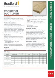
Application Guide for<br />
1Rigid Duct<br />
Internal Lining<br />
<strong>Insulation</strong><br />
2Flexible Duct<br />
<strong>Insulation</strong><br />
3Fire Control<br />
<strong>Insulation</strong><br />
4Rigid Duct<br />
External Wrap<br />
<strong>Insulation</strong><br />
5Equipment<br />
Enclosure<br />
<strong>Insulation</strong><br />
4<br />
CSR BRADFORD INSULATION
AIR CONDITIONING DESIGN GUIDE<br />
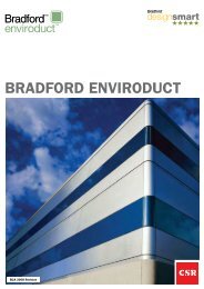
<strong>Air</strong> Conditioning Systems.<br />
Refer to Page 6 for Bradford <strong>Insulation</strong> Product Selection Recommendations.<br />
6Fan Casing<br />
<strong>Insulation</strong><br />
7Fan Silencer<br />
<strong>Insulation</strong><br />
8Chilled/Hot<br />
Water Pipe<br />
<strong>Insulation</strong><br />
9Chiller/Boiler<br />
<strong>Insulation</strong><br />
10<br />
Chilled/Hot<br />
Water Tank<br />
<strong>Insulation</strong><br />
5<br />
CSR BRADFORD INSULATION
<strong>Insulation</strong> Application<br />
1<br />
2<br />
3<br />
4<br />
5<br />
6<br />
7<br />
8<br />
Rigid Ducting<br />
Internal Lining<br />
Flexible Duct<br />
Fire Control<br />
Rigid Ducting<br />
External Wrap<br />
Equipment Enclosures<br />
AIR CONDITIONING DESIGN GUIDE<br />
Bradford <strong>Insulation</strong> Application & Selection Guide<br />
for <strong>Air</strong> Conditioning Systems.<br />
Fan Casings<br />
Fan Silencers<br />
Chilled/Hot Water Pipe<br />
9 Chillers/Boilers<br />
10 Chilled/Hot<br />
Water Tanks<br />
Product Type<br />
Bradford Glasswool SUPERTEL <br />
Bradford Glasswool DUCTLINER<br />
Bradford Glasswool ULTRATEL <br />
Bradford Glasswool DUCTEL <br />
Bradford FIBERTEX Rockwool DUCTLINER<br />
Bradford Glasswool R1.0 SPECITEL <br />
Bradford Glasswool R1.5 SPECITEL <br />
Bradford FABRIFLEX Flexible Ducting<br />
Bradford ACOUSTOFLEX Flexible Ducting<br />
Bradford FIRESEAL Loose Rockwool<br />
Bradford FIRESEAL Fire Damper Strips<br />
Bradford FIBERTEX Rockwool DUCTWRAP<br />
Bradford FIBERTEX Rockwool Pipe <strong>Insulation</strong><br />
Bradford Glasswool MULTITEL <br />
Bradford Glasswool DUCTWRAP<br />
Bradford Glasswool FLEXITEL <br />
Bradford FIBERTEX Rockwool DUCTWRAP<br />
Bradford Glasswool SUPERTEL <br />
Bradford Glasswool ULTRATEL <br />
Bradford FIBERTEX Rockwool DUCTLINER<br />
Bradford FIBERTEX 450 Rockwool<br />
Bradford Glasswool FLEXITEL <br />
Bradford Glasswool SUPERTEL <br />
Bradford Glasswool QUIETEL <br />
Bradford FIBERTEX Rockwool DUCTLINER<br />
Bradford Glasswool SUPERTEL <br />
Bradford Glasswool ULTRATEL <br />
Bradford Glasswool QUIETEL <br />
Bradford FIBERTEX Rockwool DUCTLINER<br />
Bradford FIBERTEX 450 Rockwool<br />
Bradford Glasswool Sectional Pipe <strong>Insulation</strong><br />
Bradford FIBERTEX Rockwool Sectional Pipe <strong>Insulation</strong><br />
Bradford Glasswool FLEXITEL <br />
Bradford Glasswool SUPERTEL <br />
Bradford FIBERTEX Rockwool DUCTWRAP<br />
Bradford FIBERTEX 450 Rockwool<br />
Bradford Glasswool FLEXITEL <br />
Bradford FIBERTEX Rockwool DUCTWRAP<br />
Bradford BRADFLEX FLEXIBLE DUCTING<br />
6<br />
CSR BRADFORD INSULATION
AIR CONDITIONING DESIGN GUIDE<br />
Performance Characteristics of Bradford <strong>Insulation</strong>.<br />
Bradford <strong>Insulation</strong> products suitable for use in air <strong>conditioning</strong> systems and other mechanical service applications are<br />
manufactured to meet the following performance characteristics. These characteristics are critical <strong>design</strong><br />
considerations in all mechanical services application.<br />
Performance Characteristic Bradford <strong>Insulation</strong> Bradford <strong>Insulation</strong> Bradford<br />
for Ductwork for Ductwork Pipe<br />
(External Wrap) (Internal Lining) <strong>Insulation</strong><br />
Low thermal conductivity to ensure<br />
adequate thermal performance at<br />
specified thickness ✓ ✓ ✓<br />
Sufficient compression resistance to prevent<br />
loss of thickness and thermal performance<br />
when flexed around intersections ✓ ✓ n/a<br />
Adequate flexibility to allow wrapping<br />
around ductwork ✓ n/a n/a<br />
Fire resistance to meet regulatory standards and ability<br />
to maintain integrity under fire attack ✓ ✓ ✓<br />
Ability to withstand operating temperature extremes ✓ ✓ ✓<br />
Ability to accept vapour barriers and acoustic facings ✓ ✓ ✓<br />
Non corrosive to steel ✓ ✓ ✓<br />
Sufficient compression resistance to<br />
minimise air friction & turbulence caused<br />
by unacceptable quilting of the surface n/a ✓ n/a<br />
Excellent sound absorption properties<br />
to reduce fan noise ✓ ✓ n/a<br />
Rigidity to provide stability during<br />
sheet metal duct fabrication n/a ✓ n/a<br />
Sufficient compression resistance to<br />
minimise loss of thickness and thermal<br />
performance under dead / live loads ✓ ✓ ✓<br />
Excellent sound absorption properties to<br />
reduce radiated fluid transfer noise n/a n/a ✓<br />
<strong>Insulation</strong> available in required size and<br />
thickness to ensure performance, ease of<br />
installation and proper fit ✓ ✓ ✓<br />
Ease of cutting and handling ✓ ✓ n/a<br />
Easily pinned onto rigid duct ✓ ✓ ✓<br />
Long-term durability at specified operating temperatures ✓ ✓ ✓<br />
Meets Indoor <strong>Air</strong> Quality (IAQ) requirements ✓ ✓ ✓<br />
7<br />
CSR BRADFORD INSULATION
AIR CONDITIONING DESIGN GUIDE<br />
Design Considerations.<br />
In the <strong>design</strong> of insulation for <strong>Air</strong> Conditioning Systems there are several parameters which need to be considered.<br />
The relative importance of each of these parameters will vary in individual cases and will be influenced by local<br />
climate, building aspect and <strong>design</strong>, building purpose, and the desired internal thermal and acoustic environment.<br />
CONSIDERATION<br />
Thermal Control and Energy<br />
Conservation<br />
Condensation Control<br />
Noise Control<br />
Ducted <strong>Air</strong> Velocity<br />
<strong>Air</strong> Friction Correction Factor<br />
Fire Protection<br />
Moisture Resistance and<br />
Water Repellency<br />
Mechanical Properties<br />
Durability<br />
Environmental and Biological<br />
Aspects<br />
Installed Cost<br />
Health & Safety<br />
ACTION<br />
Specify pipe or ductwork insulation thickness or R-Value to limit heat gain<br />
or loss in system<br />
Design insulation thickness and vapour barrier type for expected<br />
atmospheric conditions<br />
Choose insulation of density and thickness with correct facing type for<br />
control of equipment and air flow noise throughout system<br />
Select insulation and facing to resist air erosion and minimise frictional resistance<br />
Allow for air frictional losses in the air ducting system<br />
Ensure the fire performance requirements of insulation materials are met<br />
Select material with high water repellency and low moisture absorption<br />
Ensure the dimensional stability, compressive strength, rigidity or flexibility<br />
requirements for the application are satisfied by the selected insulation<br />
Select insulation capable of enduring long term effects of the application<br />
and operating conditions<br />
Choose environmentally friendly insulation products for ecological<br />
sustainable <strong>design</strong><br />
Select insulation products and systems for ease and speed of installation<br />
Observe CSR Bradford <strong>Insulation</strong> MSDS recommendations<br />
Thermal Control &<br />
Energy Conservation.<br />
Proper <strong>design</strong> of the building envelope, and the<br />
components of the systems used to achieve comfort<br />
within it, requires an understanding of thermal<br />
insulation and the thermal behaviour of insulated<br />
assemblies.<br />
The Bradford <strong>Insulation</strong> Building Design Guide<br />
provides data and examples to equip the <strong>design</strong>er with<br />
basic information necessary to provide for good<br />
building envelope thermal performance.<br />
It is also necessary to insulate ducting, piping,<br />
fittings and equipment components of air <strong>conditioning</strong><br />
systems. <strong>Insulation</strong> <strong>design</strong> gives consideration to<br />
requirements for control of delivery temperatures,<br />
energy conservation and personnel protection.<br />
8<br />
CSR BRADFORD INSULATION
AIR CONDITIONING DESIGN GUIDE<br />
The cost of energy, and particularly the energy cost<br />
of refrigeration, justify assessment of the performance,<br />
and therefore of the thickness, of insulation which<br />
represents an economic investment over the life of an<br />
air <strong>conditioning</strong> system. This is one component of<br />
energy efficient <strong>design</strong> which can economically (in<br />
relation to capital investment) minimise operating costs.<br />
In summer the temperature of air in the supply<br />
ducting will be lower than the air surrounding the<br />
duct. The converse is true in winter. <strong>Insulation</strong> applied<br />
to the duct surface can reduce heat transfer to predetermined<br />
acceptable levels.<br />
Return air ducts convey air at the same temperature<br />
and humidity as that of the conditioned space. It may<br />
be necessary to insulate return air ducts installed in<br />
non-conditioned spaces, such as risers or plant rooms,<br />
to minimise heat transfer and energy required to<br />
recondition the return air.<br />
<strong>Insulation</strong> requirements for ductwork may be<br />
<strong>design</strong>ed on the basis of the heat gain or loss through<br />
the duct, calculated as a function of temperature<br />
differentials, surface coefficients and the thermal<br />
resistance value of the bulk insulation.<br />
Table 3 in the Design Calculations section of this<br />
<strong>guide</strong> entitled ‘Heat Gain by Ducted <strong>Air</strong> in Summer<br />
Conditions’, provides a set of calculated typical heat<br />
gains for selected thicknesses of Bradford Glasswool or<br />
Fibertex Rockwool Ductliner bulk insulation<br />
products.<br />
Findings from the economic evaluation of<br />
insulation options from modelling building<br />
performance in various climates are shown in Table 1.<br />
These recommended insulation standards for energy<br />
conservation in rigid and flexible air <strong>conditioning</strong><br />
ducting for commercial and residential applications,<br />
were derived from comprehensive modelling work<br />
conducted by Standards Australia across the various<br />
climatic zones in Australia.<br />
AS4508 ‘Thermal Resistance of <strong>Insulation</strong> for<br />
Ductwork used in Building <strong>Air</strong> Conditioning’<br />
was published in 1999 and follows similar<br />
standards in the USA and Europe.<br />
These standards would represent the minimum for<br />
air <strong>conditioning</strong> duct work insulation in Asia where<br />
higher temperature and humidity combined with high<br />
energy costs would justify even greater R-values.<br />
These recommended minimum R-values are a<br />
<strong>guide</strong> only and mechanical services engineers should<br />
calculate the correct levels of insulation to be used to<br />
optimise energy conservation, acoustics and<br />
condensation control. Your nearest Bradford <strong>Insulation</strong><br />
office would be able to assist with these calculations.<br />
TABLE 1. MINIMUM BULK<br />
THERMAL RESISTANCE R-VALUES.<br />
Minimum R System Application<br />
Value (m 2 K/W)<br />
1.5 Ductwork -combined<br />
heating and refrigerative cooling<br />
0.9 Ductwork - Heating or<br />
refrigerative cooling only<br />
0.6 Ductwork - Evaporative Cooling<br />
Source: AS4508 : 1999 ‘Thermal Resistance of insulation for ductwork used<br />
in building air <strong>conditioning</strong>’.<br />
The correct insulation thickness should be selected<br />
based on the thermal resistance performance of the<br />
bulk insulation at the <strong>design</strong> operating temperatures.<br />
The Thermal Resistance R-Value is calculated as<br />
R = L/k, where k = thermal conductivity (W/mK) at<br />
mean temperatures, as per Table 2, L = <strong>Insulation</strong><br />
Thickness (m).<br />
TABLE 2.<br />
THERMAL CONDUCTIVITY (W/mK).<br />
Bradford <strong>Insulation</strong> Mean Temperature<br />
Type 20ºC 40ºC 60ºC<br />
Bradford Glasswool<br />
MULTITEL 0.035 0.042 0.045<br />
DUCTWRAP 0.034 0.042 0.045<br />
Bradford Glasswool<br />
FLEXITEL 0.033 0.037 0.042<br />
Bradford Glasswool<br />
SUPERTEL <br />
DUCTLINER 0.032 0.036 0.039<br />
Bradford Glasswool<br />
ULTRATEL 0.031 0.035 0.037<br />
Bradford FIBERTEX <br />
Rockwool DUCTWRAP/<br />
DUCTLINER 0.034 0.038 0.042<br />
In air <strong>conditioning</strong> system pipework, modulation of<br />
the flow rate of heating or cooling water may be the<br />
means by which energy flows to the air <strong>conditioning</strong><br />
system are controlled. If this is the case, the insulation<br />
system should be <strong>design</strong>ed to control heat loss or gain<br />
through the pipe wall. This will ensure predictable fluid<br />
temperatures at each discharge point in the system.<br />
Piping or equipment may be required to be<br />
insulated for personnel protection, to ensure that<br />
accessible exposed surfaces do not operate at<br />
temperature above 55° - 65°C.The thickness of<br />
insulation determined to meet energy conservation or<br />
temperature control criteria will normally be adequate.<br />
In the case of exhaust flues or stacks from boilers or<br />
stand-by generator (diesel) motors, the governing<br />
9<br />
CSR BRADFORD INSULATION
AIR CONDITIONING DESIGN GUIDE<br />
requirement will usually be sufficient insulation<br />
thickness to provide safe touch temperature for service<br />
personnel. <strong>Insulation</strong> <strong>design</strong> information for high<br />
temperature applications such as this is included in the<br />
Bradford <strong>Insulation</strong> Industrial Design Guide.<br />
Detailed data, formulae and worked examples are<br />
given in the Design Calculation section of this <strong>guide</strong>.<br />
Condensation Control.<br />
Condensation of atmospheric moisture will occur<br />
on any surface which is at or below the dew point<br />
temperature of the air in contact with that surface. In<br />
the case of ductwork prevention of such condensation<br />
requires the installation of thermal insulation on the<br />
inside of the duct, or insulation plus a Thermofoil<br />
vapour barrier on the outside of the duct. In this case<br />
the Thermofoil should be factory adhered to the<br />
outside of the insulation. <strong>Insulation</strong> thickness required<br />
to control condensation may be calculated taking into<br />
account;<br />
• Ducted air velocity<br />
• Ducted air temperature (minimum)<br />
• Temperature of the surrounding air (maximum)<br />
See the Design Calculation section of this <strong>guide</strong> for<br />
<strong>design</strong> examples of condensation control.<br />
Under operating conditions, condensation may be<br />
possible on refrigerant or chilled water piping.<br />
<strong>Insulation</strong> of sufficient thickness installed with a<br />
vapour barrier will prevent condensation. Pipe<br />
supports should, where possible, be external to the<br />
insulation and vapour barrier. Alternatively, the vapour<br />
barrier system should be continuous through the pipe<br />
support.<br />
Noise Control.<br />
Noise arises in air <strong>conditioning</strong> systems principally<br />
from fans and from air flow generated noise in both<br />
ducts and through registers. In addition, it is sometimes<br />
necessary to deal with sound transmitted along a duct<br />
from one room to another. <strong>Insulation</strong> systems with<br />
applied facings must provide adequate sound<br />
absorption to ensure that effective Noise Insertion Loss<br />
performance is achieved.<br />
To control the noise generated by the fan to which<br />
the duct is attached, the insulation ductliner should be<br />
installed inside the duct, immediately ‘downstream’<br />
from the fan. Similarly, to reduce room to room noise<br />
transmission along the duct, the insulation system<br />
should be installed in the duct from immediately inside<br />
the supply register of the noisy room. To ensure<br />
maximum noise controlling properties the internal<br />
duct insulation should be faced with an acoustically<br />
transparent facing such as perforated Thermofoil or<br />
black matt tissue.<br />
If internal insulation alone is not deemed to reduce<br />
noise transmission through the duct walls sufficiently,<br />
then the addition of external insulation together with<br />
an appropriate heavy outer finish, will achieve the<br />
desired result.<br />
Bradford Glasswool and Fibertex Ductliner<br />
products have excellent sound absorption qualities,<br />
refer to the Noise Control section under Design<br />
Calculations for further details.<br />
Bradford Acoustilag for noise insulation of pipes,<br />
and Bradford Acousticlad for industrial noise<br />
absorption are also available. Please refer to the<br />
Bradford <strong>Insulation</strong> Acoustic Design Guide for more<br />
details.<br />
Ducted <strong>Air</strong> Velocity.<br />
When installed inside the duct, the insulation<br />
material and its surface facing must be able to resist<br />
erosion by the high velocity ducted air and also offer<br />
the least possible frictional resistance.<br />
Bradford Glasswool and Fibertex Rockwool<br />
Ductliners with factory applied surface facings have<br />
been tested for surface erosion at extreme velocities by<br />
the quantitative method developed by the CSR<br />
Building Research Material Laboratories and based on<br />
Underwriters Laboratory Standard UL181. On the<br />
basis of these results and air friction correction factors,<br />
maximum <strong>design</strong> velocities are recommended for<br />
Bradford Glasswool or Fibertex Ductliners. Refer to<br />
Page 27 in the Design Calculations section for <strong>Air</strong><br />
Friction for maximum <strong>design</strong> velocities.<br />
10<br />
CSR BRADFORD INSULATION
AIR CONDITIONING DESIGN GUIDE<br />
<strong>Air</strong> Friction<br />
Correction Factor.<br />
The energy absorbed in frictional losses in the air<br />
<strong>conditioning</strong> system may be significant, particularly for<br />
high velocity systems. The usual procedure for<br />
determining friction losses in air ducts is by use of the<br />
<strong>Air</strong> Friction Charts published in the ASHRAE<br />
Handbook of Fundamentals and the IHVE Guide.<br />
Refer to FIG 7, page 27 in the Design Calculations<br />
section of this <strong>guide</strong> for <strong>Air</strong> Friction Correction<br />
Factors.<br />
Fire Protection.<br />
<strong>Air</strong> <strong>conditioning</strong> systems in buildings are <strong>design</strong>ed<br />
to ensure fire does not propagate along ductwork and<br />
that all duct and pipe penetrations through walls and<br />
floors are adequately sealed against fire ingress with fire<br />
dampers, collars and fire resistant perimeter details.<br />
Bradford <strong>Insulation</strong> products for air <strong>conditioning</strong><br />
systems do not burn and provide excellent protection<br />
against fire. Fibertex Rockwool offers superior fire<br />
resistance due to its very high fusion temperature of<br />
greater than 1150°C.<br />
as determined in accordance with AS1530 : Part 3 –<br />
1989, when tested on the exposed face of the internal<br />
and/or external insulation.<br />
All Bradford Glasswool and Fibertex Rockwool<br />
products comply with these requirements and have<br />
excellent early fire hazard performance when tested to<br />
AS1530.3, ASTM E84, BS476 or equivalent.<br />
For compliance with other international standards<br />
such as UL181, please refer to the Bradford <strong>Insulation</strong><br />
office in your region.<br />
NON - COMBUSTIBILITY.<br />
Bradford Glasswool HT Thermatel and all Bradford<br />
Fibertex Rockwool have a low content of organic<br />
binder and are deemed to be non-combustible<br />
insulation materials when tested to AS1530.1,<br />
BS476.4, ASTM or equivalent.<br />
Australian Standard AS1668.1 Part 1 ‘Fire and<br />
smoke control in multi-compartment buildings’<br />
prescribes that materials used in ductwork for fire<br />
dampers, smoke spill and exhaust systems shall be<br />
deemed to be non-combustible in accordance with<br />
AS1530.1 – 1989.<br />
EARLY FIRE HAZARD.<br />
Early fire hazard performance is determined in<br />
accordance with Australian Standard AS1530 : Part 3 –<br />
1989. The test indices provide a measurement for<br />
ignitability, heat evolved, spread of flame and smoke<br />
developed. The lower the index, the less hazardous the<br />
material is considered to be.<br />
Australian Standards AS4254 ‘Ductwork for <strong>Air</strong><br />
Handling Systems in Buildings’ prescribes<br />
i) A spread of flame index number not greater than<br />
0, and<br />
ii)A smoke developed index number not greater<br />
than 3<br />
FIRE RESISTANCE.<br />
A high level of fire resistance in insulation and<br />
other materials used in air <strong>conditioning</strong> systems is<br />
essential to protect building occupants in case of fire<br />
and to limit the extent of damage to plant, building<br />
and equipment.<br />
Bradford Rockwool and Glasswool insulation<br />
produces no toxic fumes when subject to fire<br />
conditions and are used successfully in one & two hour<br />
rated fire protection systems which allow building<br />
occupants to escape safely.<br />
Bradford Fibertex Rockwool provide high levels of<br />
fire resistance due to their low thermal diffusivity and<br />
are able to withstand fire with only slow breakdown in<br />
physical properties when tested to AS1530.4, BS476,<br />
ASTM or equivalent.<br />
Bradford Fireseal products are specialty fire grade<br />
rockwool offering outstanding fire resistance for long<br />
periods making them suitable for fire sealing<br />
applications in party walls, fire dampers and pipe/cable<br />
penetrations.<br />
11<br />
CSR BRADFORD INSULATION
AIR CONDITIONING DESIGN GUIDE<br />
For pipe penetrations through concrete slabs, block<br />
wall or lightweight partitions, steel or copper pipe<br />
should be lagged with non-combustible Bradford<br />
Fibertex Rockwool or Glasswool Sectional Pipe<br />
<strong>Insulation</strong> and all gaps sealed with an intumescent<br />
mastic. For chilled water pipes the external vapour<br />
barrier must be continuous for condensation control.<br />
Moisture Resistance &<br />
Water Repellency.<br />
MOISTURE ABSORPTION.<br />
Excessive moisture will reduce the thermal<br />
insulation performance of an insulation material.<br />
Exposure of Bradford Glasswool or Fibertex<br />
Rockwool to a controlled atmosphere of 50°C and<br />
95% relative humidity for 96 hours results in water<br />
vapour absorption of less than 0.2% by volume, in<br />
accordance with ASTM C1104.<br />
WATER REPELLENCY.<br />
Should rockwool or glasswool insulation become<br />
wet full thermal efficiency will be restored on drying<br />
out.<br />
Bradford Fibertex WR is a specialty water-repellent<br />
rockwool developed by Bradford Research<br />
Laboratories for applications subject to water ingress.<br />
The water repelling agents contained in Fibertex WR<br />
have been engineered to ensure maximum resistance to<br />
water penetration.<br />
Fibertex WR is non-hydroscopic and will absorb<br />
water only when forced in under pressure. Once the<br />
pressure is relieved the water will evaporate out,<br />
leaving the material dry with maximum insulating<br />
value. If Fibertex WR is exposed to a spray or rain<br />
then water will usually only penetrate only a few<br />
millimetres into the surface, which effect the insulating<br />
properties.<br />
When tested in accordance with BS2972 ‘Total<br />
Immersion in Water’, Bradford Fibertex WR absorbs<br />
less than 1% moisture by volume.<br />
VAPOUR DIFFUSION.<br />
Bradford Glasswool and Fibertex Rockwool consist<br />
of an open, inert air cell structure which provides<br />
negligible resistance to water vapour diffusion,<br />
allowing water vapour to pass through without<br />
condensing or absorbing.<br />
However, should the outer cladding or fibres be<br />
allowed to fall below dew point temperature at<br />
prevailing relative humidity and temperature then<br />
condensation may occur.<br />
Mechanical Properties.<br />
COMPRESSIVE STRENGTH.<br />
Bradford Glasswool and Fibertex Rockwool are<br />
resilient insulation materials which readily recover to<br />
the nominal thickness after the removal of a normal<br />
compressive load. Higher density glasswool or<br />
rockwool materials offer greater compression<br />
resistance, and correct densities should be specified for<br />
use in areas subject to live or dead loads.<br />
RIGIDITY AND FLEXIBILITY.<br />
To ensure thermal insulation performs as intended<br />
it is essential that the insulating material is installed and<br />
held firmly against the surface being insulated.<br />
Bradford Glasswool and Fibertex Rockwool<br />
insulation in rigid and semi-rigid board offer excellent<br />
deflection resistance for insulating areas where<br />
excessive sag can occur, such as the underside of wide<br />
duct and soffits. Flexible blankets are easy to apply and<br />
are particularly suitable for insulating around small<br />
radius bends and curved surfaces.<br />
Durability &<br />
Mechanical Damage.<br />
Durability under operating conditions can generally<br />
only be determined from experience. Bradford<br />
Glasswool and Fibertex Rockwool insulation products<br />
enjoy a proven record of efficient, durable service in a<br />
wide range of air <strong>conditioning</strong> duct and pipework<br />
applications. The insulation system must;<br />
• Accommodate thermal movement and resist<br />
settling, breakdown or sagging from vibration of<br />
the insulated surface.<br />
• Continue to provide efficient thermal resistance<br />
throughout the economic life of the insulated<br />
equipment.<br />
• Be thermally stable across variable operating<br />
temperatures.<br />
Bradford Glasswool and Fibertex Rockwool<br />
insulation meet these durability criteria.<br />
Externally applied insulation and vapour barrier<br />
systems are vulnerable to mechanical damage from<br />
equipment or personnel, particularly where the<br />
ducting is operating in exposed locations such as<br />
service corridors and plant rooms. Where the ducting<br />
is installed above suspended ceilings, the risk of damage<br />
is minimal.<br />
12<br />
CSR BRADFORD INSULATION
AIR CONDITIONING DESIGN GUIDE<br />
Damage to the vapour barrier where it is<br />
penetrated may result in condensation of atmospheric<br />
water vapour within the insulation or on the metal<br />
ducting. This can reduce the performance of the<br />
insulation system and cause water dripping into the<br />
space below the duct. External insulation systems can<br />
be protected using metal screens or completely<br />
cladding the insulation with sheet metal.<br />
For outdoor applications adequate reinforcement<br />
and cladding systems shall be employed for weather<br />
protection.<br />
Environmental and<br />
Biological Aspects.<br />
ENVIRONMENTAL.<br />
Bradford Glasswool and Fibertex Rockwool<br />
products are manufactured using highly abundant<br />
naturally occurring raw material including a high<br />
proportion of recycled matter. The molten mixtures<br />
are spun into fibres and bonded together with organic<br />
resin.<br />
Bradford <strong>Insulation</strong> plants utilise the latest<br />
technology in manufacturing processes, coupled with<br />
best energy efficiency practice to ensure the embodied<br />
energy of the final glasswool and rockwool material is<br />
kept to a minimum. Bradford is committed to<br />
producing ecologically sustainable materials for the<br />
long term benefit of the environment.<br />
BIOLOGICAL.<br />
Environments with warm, moist conditions can be<br />
susceptible to biological growth if not correctly<br />
guarded against. Preventing condensation through<br />
adequate thermal control using Bradford Glasswool<br />
and Fibertex Rockwool bulk insulation with<br />
appropriate facings will inhibit mould growth.<br />
Should mould initiate and propagate from another<br />
source glasswool and rockwool will not sustain any<br />
growth of biological matter.<br />
The Bradford <strong>Insulation</strong> office in your region can<br />
also assist with information about specialist anti-fungal<br />
products.<br />
Installed Cost.<br />
<strong>Insulation</strong> materials should be selected by<br />
considering the total installed cost. Influencing factors<br />
include material purchase costs, installation costs<br />
including labour and equipment and cost of materials<br />
damaged during handling and installation.<br />
Bradford Fibertex Rockwool and Glasswool<br />
products are resilient and lightweight, resulting in ease<br />
of handling and minimum accidental damage during<br />
installation. Their ease of cutting, detailing and<br />
securing around ducting and pipework ensure minimal<br />
installation time.<br />
Convenient standard and custom roll or sheet sizes<br />
in a wide range of thicknesses ensure that the required<br />
total thickness of insulation may be quickly and<br />
economically installed. A range of factory applied<br />
facings are available to meet the acoustic and/or<br />
vapour sealing needs of the air <strong>conditioning</strong> system.<br />
Easy handling on site, particularly on scaffolding<br />
and in confined spaces around process vessels and<br />
piping, not only reduces labour costs but also<br />
contributes to meeting completion dates.<br />
Health & Safety.<br />
Bradford Glasswool and Fibertex Rockwool<br />
products have been widely used in industry for several<br />
generations. There is no evidence to demonstrate any<br />
long term health effects from these products used in<br />
accordance with the simple procedures of the National<br />
WorkSafe Standard and Code of Practice for the Safe<br />
Use of Synthetic Mineral Fibres.<br />
Full health and safety information is provided in the<br />
CSR Bradford <strong>Insulation</strong> Material Safety Data Sheets<br />
available on request.<br />
13<br />
CSR BRADFORD INSULATION
AIR CONDITIONING DESIGN GUIDE<br />
Design Calculations.<br />
Thermal Control.<br />
Heat Flow Rate through a uniformly insulated duct<br />
wall for a duct of rectangular section is given by the<br />
equation:<br />
Where:<br />
Q = heat loss rate (W/m 2 )<br />
t da = temperature of ducted air (°C)<br />
t a = ambient air temperature (°C)<br />
L = thickness of insulation (m)<br />
k = thermal conductivity of insulation (W/m.K)<br />
f i = internal surface coefficient (W/m 2 .K)<br />
= external surface coefficient (W/m 2 .K)<br />
f o<br />
L<br />
k<br />
1<br />
f i<br />
1<br />
f o<br />
Q =<br />
1<br />
( fi<br />
t da – t a<br />
+<br />
L<br />
k<br />
+<br />
1<br />
f o<br />
)<br />
= thermal resistance of insulation<br />
= internal air surface resistance<br />
= external air surface resistance<br />
In using this formula, the insulation thicknesses<br />
must be expressed in metres, not millimetres.<br />
Note that for hot air ducts, t da will be greater than<br />
t a and Q will be positive.<br />
For cold air ducts, t da will be less than t a and Q will<br />
be negative, indicating a reversal in the direction of<br />
heat flow.<br />
Heat transfer and outside surface temperatures are<br />
listed in Table 3 for a range of ambient and ducted air<br />
temperatures.<br />
The internal surface film conductance, f i , was taken<br />
as 12.4W/m 2 .K based on air velocity 10m/s<br />
(1,968fpm) in a galvanised steel duct.<br />
WINTER CONDITIONS.<br />
Table 3 may also be used to estimate the heat loss<br />
from hot air ducts by assuming the ducted air<br />
temperature to be the ambient temperature as shown<br />
and vice versa. Surface temperatures of insulated hot<br />
air ducts have no significance in winter conditions as<br />
no condensation problems are involved.<br />
TABLE 3. HEAT GAIN BY DUCTED AIR IN SUMMER CONDITIONS.<br />
Q = Heat Gain by Ducted <strong>Air</strong>. t s = External Surface Temperature.<br />
Temp of <strong>Insulation</strong><br />
Ambient Temperature<br />
Ducted <strong>Air</strong> Thickness 20°C 25°C 30°C 35°C<br />
°C mm Q (W/m 2 ) t s °C Q (W/m 2 ) t s °C Q (W/m 2 ) t s °C Q (W/m 2 ) t s °C<br />
5 25 15.9 18.4 21.4 22.9 27.1 27.3 32.9 31.8<br />
50 8.8 19.1 11.9 23.8 15.1 28.5 18.3 33.2<br />
10 25 10.7 18.9 16.3 23.4 22.0 27.8 27.8 32.3<br />
50 6.0 19.4 9.1 24.1 12.2 28.8 15.5 33.5<br />
15 25 5.5 19.5 11.0 23.9 16.7 28.4 22.6 32.8<br />
50 3.0 19.7 6.1 24.4 9.3 29.1 12.6 33.8<br />
20 25 - - 5.6 24.5 11.3 28.9 17.2 33.3<br />
50 - - 3.1 24.7 6.3 29.4 9.6 34.1<br />
5 25 14.6 17.4 19.7 21.5 24.9 25.6 30.1 29.7<br />
50 8.4 18.5 11.3 23.0 14.3 27.5 17.4 31.9<br />
10 25 9.9 18.3 15.0 22.4 20.2 26.4 25.5 30.5<br />
50 5.7 19.0 8.6 23.5 11.6 27.9 14.7 32.4<br />
15 25 5.0 19.1 10.1 23.2 15.4 27.3 20.7 31.4<br />
50 2.9 19.5 5.8 24.0 8.9 28.4 12.0 32.9<br />
20 25 - - 5.1 24.1 10.4 28.2 15.7 32.2<br />
50 - - 3.0 24.5 6.0 28.9 9.1 33.4<br />
Non-reflective Outside Surface<br />
Reflective Outside Surface<br />
14<br />
CSR BRADFORD INSULATION
AIR CONDITIONING DESIGN GUIDE<br />
SURFACE HEAT TRANSFER<br />
COEFFICIENTS.<br />
The External Surface Coefficient or Surface Film<br />
Conductance, f o , is the time rate of heat transfer<br />
between the outside surface of the insulation or<br />
cladding and the surrounding air. Heat is transmitted at<br />
the surface by both convection and radiation, but for<br />
convenience the two are combined and expressed as a<br />
conductance.<br />
The value of the coefficient varies widely and is<br />
influenced by the physical state of the surface, its<br />
temperature and emissivity, the temperature difference<br />
between the surface and the surrounding atmosphere,<br />
the dimensions, shape and orientation of the surface,<br />
and the velocity of air in contact with it.<br />
The use of a reflective cladding or facing lowers the<br />
external surface coefficient. This has little effect on the<br />
overall heat flow, but results in surface temperatures<br />
considerably higher in the case of hot air ducts and<br />
considerably lower for cold air ducts.<br />
Recommended values for the external surface<br />
coefficient for still air conditions are shows in Table 4.<br />
TABLE 4. SURFACE COEFFICIENTS.<br />
Surface<br />
f o (W/m 2 .K)<br />
Aluminium sheet, foil and foil laminates 5.7<br />
Zincalume 6.3<br />
Galvanised steel 6.3<br />
Zincanneal 8.0<br />
Bare insulation, mastics and darker paints 10.0<br />
<strong>Air</strong> velocity can also have a considerable effect on<br />
the surface temperature and the overall heat<br />
transmission. The effect of increasing air velocity will<br />
be to decrease the cladding temperature of a hot vessel<br />
and increase that of a cold vessel. This may be<br />
important in condensation prevention.<br />
FIG 1. EXTERNAL SURFACE<br />
HEAT TRANSFER COEFFICIENT vs AIR VELOCITY.<br />
Heat Transfer Coefficient<br />
W/m 2 K<br />
40<br />
30<br />
20<br />
10<br />
0<br />
0<br />
Non Reflective<br />
2 4 6 8 10<br />
<strong>Air</strong> Velocity m/sec<br />
Reflective<br />
Figure 1 indicates the effect of air velocity on the<br />
external surface coefficient for a reflective cladding,<br />
e.g. aluminium and a typical non-reflective surface<br />
finish. The curves shown are for a surface temperature<br />
of 50°C and an ambient air temperature of 20°C.<br />
The Internal Surface Coefficient or Surface Film<br />
Conductance, f i , is the time rate of heat transfer<br />
between the internal surface of the duct and the<br />
transported air.<br />
Heat transfer from and to the internal duct wall<br />
surface is almost entirely by convection. Therefore the<br />
value of f i , will depend mainly on the physical state of<br />
the surface, the velocity of the ducted air and the<br />
difference between its temperature and that of the<br />
surface.<br />
Recommended values for the internal surface<br />
coefficient for a galvanised steel duct operating within<br />
the range of temperatures normally used in air<br />
<strong>conditioning</strong> are given in Table 5.<br />
TABLE 5.<br />
INTERNAL SURFACE COEFFICIENTS.<br />
Ducted <strong>Air</strong> Velocity m/s<br />
f i (W/m 2 .K)<br />
5 9.4<br />
10 12.4<br />
15 14.5<br />
OUTSIDE SURFACE TEMPERATURE.<br />
The Outside Surface Temperature, t s , may be<br />
calculated from the following formula (note Q is<br />
negative for cold ducts – heat gain):<br />
t s =<br />
Q<br />
f o<br />
THERMAL EFFICIENCY.<br />
Tender documents sometimes require a statement of<br />
insulation efficiency. Expressed as a percentage it may<br />
be calculated by the following formula:<br />
Q b - Q i<br />
Q b<br />
+<br />
t a<br />
x 100<br />
where Q b = Heat loss from bare surface<br />
Q i = Heat loss from insulated surface<br />
Values for bare surface heat loss or gain are listed in<br />
Table 6. They are based on the heat transfer between a<br />
flat surface of high emissivity and still air at 20°C.<br />
15<br />
CSR BRADFORD INSULATION
AIR CONDITIONING DESIGN GUIDE<br />
TABLE 6.<br />
BARE SURFACE HEAT TRANSFER.<br />
Surface Temperature<br />
Heat Loss or Gain<br />
°C W/m 2<br />
40 198<br />
35 142<br />
30 90<br />
25 41<br />
Surface Temperature<br />
Heat Loss or Gain<br />
°C W/m 2<br />
15 -40<br />
10 -84<br />
5 -130<br />
TABLE 7. THERMAL CONDUCTIVITY.<br />
The thermal conductivity of Bradford Glasswool and Fibertex Rockwool varies with the mean temperature of<br />
the insulation, as shown in Table 7. Test measurements are made in accordance with AS2526 Part 5 and 6, BS874,<br />
ASTM C518 and ASTM C177. Pipe <strong>Insulation</strong> testing in accordance with ASTM C335.<br />
NOTE: Tables provide typical values only. Products may vary slightly from plant to plant. Please refer to the<br />
Product Data Sheets, or contact the CSR Bradford <strong>Insulation</strong> office in your region for product recommendations for<br />
your project and assistance with heat loss calculations.<br />
IMPORTANT: CSR Bradford <strong>Insulation</strong> recommends <strong>design</strong>ers include a safety margin into heat loss calculations<br />
by always rounding up the thickness of insulation determined to the next standard thickness instead of rounding down.<br />
Thermal Conductivity (W/mK)<br />
Bradford <strong>Insulation</strong> Mean Temperature °C<br />
Product 20°C 40°C 60°C 100°C 200°C<br />
Bradford Glasswool MULTITEL 0.035 0.042 0.045 – –<br />
Bradford Glasswool DUCTWRAP 0.034 0.042 0.045 – –<br />
Bradford Glasswool FLEXITEL 0.033 0.037 0.042 0.052 –<br />
Bradford Glasswool SUPERTEL /DUCTLINER 0.032 0.036 0.039 0.049 0.080<br />
Bradford Glasswool ULTRATEL 0.031 0.035 0.037 0.045 0.068<br />
Bradford Glasswool DUCTEL 0.031 0.034 0.037 0.042 0.063<br />
Bradford Glasswool QUIETEL 0.031 0.034 0.036 0.041 0.059<br />
Bradford Glasswool Pipe <strong>Insulation</strong> 0.032 0.035 0.037 0.041 0.057<br />
Bradford FIBERTEX Rockwool<br />
DUCTLINER/DUCTWRAP 0.034 0.038 0.042 0.046 0.071<br />
Thermal Conductivity (W/mK)<br />
Bradford <strong>Insulation</strong> Mean Temperature °C<br />
Product 20 50 100 200 300 400 500 600<br />
FIBERTEX Rockwool 350 0.034 0.038 0.047 0.072 0.108 - - -<br />
FIBERTEX Rockwool 450 0.034 0.038 0.045 0.065 0.092 0.126 - -<br />
FIBERTEX Rockwool 650 0.034 0.037 0.044 0.064 0.089 0.118 0.150 0.189<br />
FIBERTEX Rockwool 820 0.034 0.037 0.044 0.059 0.090 0.118 0.145 0.180<br />
FIBERTEX Rockwool HD 0.033 0.037 0.043 0.060 0.081 0.111 - -<br />
FIBERMESH Rockwool 350 0.034 0.038 0.047 0.072 0.108 - - -<br />
FIBERMESH Rockwool 450 0.034 0.038 0.045 0.065 0.092 0.126 - -<br />
FIBERMESH Rockwool 650 0.034 0.037 0.044 0.064 0.090 0.118 0.150 0.189<br />
FIBERTEX Rockwool Pipe <strong>Insulation</strong> 0.034 0.037 0.042 0.058 0.078 0.106 0.140 0.180<br />
For conversion 1W/mK = 6.9335 Btu.in/ft 2 hºF<br />
16<br />
CSR BRADFORD INSULATION
AIR CONDITIONING DESIGN GUIDE<br />
HEAT TRANSFER CALCULATIONS.<br />
Examples for Flat and Curved Surfaces<br />
Example 1: Determining heat loss and surface<br />
temperature.<br />
A supply air riser operates in a masonry shaft in a<br />
multi-storey building.<br />
The supply air temperature is controlled at 24°C in<br />
winter and the air temperature in the unconditioned<br />
riser, in the worst case, will be 10°C.<br />
Determine the heat loss and surface temperature,<br />
assuming still air conditions, and that the insulation is<br />
25mm thick Glasswool, faced with reinforced<br />
aluminium foil.<br />
Ducted air velocity 5m/s<br />
f i = 9.4W/m 2 K<br />
Assume surface temp 14°C<br />
Mean Temperature =<br />
Thermal conductivity k = 0.033 W/m 2 K for<br />
Bradford Glasswool Flexitel.<br />
The recommended outside surface heat transfer<br />
coefficient for aluminium for still air conditions is<br />
5.7W/m 2 K.<br />
The first trial calculation for heat loss will be<br />
Q =<br />
=<br />
14<br />
=<br />
0.106 + 0.758 + 0.175<br />
=<br />
= 13.47 W/m 2<br />
Using this value for Q, the outside surface<br />
temperature can be calculated<br />
=<br />
=<br />
1 L<br />
( (t da – t a )<br />
+ +<br />
f i k<br />
(<br />
Q<br />
f o<br />
1<br />
9.4<br />
14<br />
1.039<br />
+<br />
13.47<br />
5.7<br />
t a<br />
(24 – 10)<br />
+<br />
+10<br />
.025<br />
.033<br />
24 + 14<br />
2<br />
1<br />
f o<br />
)<br />
+<br />
1)<br />
5.7<br />
)<br />
= 19°C<br />
A recalculation is now made using 12°C as the<br />
surface temperature.<br />
Mean Temperature =<br />
Thermal conductivity k = 0.033W/m 2 K<br />
Q =<br />
=<br />
= 13.63 W/m 2<br />
Using this value for Q, the outside surface<br />
temperature will be<br />
t s =<br />
0.106<br />
14<br />
1.027<br />
13.63<br />
5.7<br />
+<br />
14<br />
0.025<br />
0.0335<br />
24 + 12<br />
2<br />
+ 10 = 12.4°C<br />
0.175<br />
This is close enough to the surface temperature<br />
assumed for this recalculation. The heat loss of<br />
13.63W/m 2 may therefore be used for heating load<br />
<strong>design</strong> purposes.<br />
Example 2: Determining thickness of insulation<br />
to achieve a required surface temperature.<br />
A 1200mm duct from a tunnel kiln is expected to<br />
reach a temperature as high as 520°C. It is to be insulated<br />
for personnel protection, <strong>design</strong>ing for a cladding<br />
temperature not exceeding 62°C when the ambient<br />
temperature is at the anticipated maximum of 32°C.<br />
Calculations are to based on still air conditions.<br />
What insulation and cladding system should be<br />
specified and what thicknesses will be required?<br />
As the duct diameter is greater than the largest preformed<br />
pipe insulation produced, Fibertex batts and<br />
blankets are the obvious choice of insulation material.<br />
At 520°C hot face temperature, it will be necessary to<br />
use kerfed Fibertex 650 batts for the inner layer; the<br />
outer layer should be Fibertex 450 blankets.<br />
To assist in achieving low surface temperature, the<br />
cladding should be zincanneal or galvanised steel<br />
painted a dark colour. This permits the use of a value<br />
of 10.0W/m 2 .K for the surface heat transfer coefficient<br />
(refer to Table 4).<br />
The use of flat surface formulae in the calculations<br />
will be accurate enough for such a large diameter duct.<br />
+<br />
= 18°C<br />
= 12.36°C<br />
17<br />
CSR BRADFORD INSULATION
AIR CONDITIONING DESIGN GUIDE<br />
The outside surface temperature of the insulation<br />
system is given by the formula:<br />
t =<br />
Using the stated maximum values for ts and ta, a<br />
maximum allowable value for the heat transfer, Q, can<br />
be found:<br />
62 =<br />
from which, the maximum value for Q is<br />
300W/m 2 .<br />
The correct combination of standard thicknesses of<br />
the two insulation materials must now be determined<br />
to ensure that this value of Q is not exceeded and also<br />
that the junction temperature, t j , between the two<br />
materials is not greater than 450°C, the top service<br />
temperature for Fibertex 450.<br />
This is done by trial and error. As a first estimate it<br />
can be assumed that 38mm of Fibertex 650 and 85mm<br />
of Fibertex 450 may be close to the solution required.<br />
In dual layer calculations, it is wise to aim at a<br />
junction temperature a little below the top service<br />
limit of the outer layer as a safety precaution. In this<br />
case, an initial figure of 425°C for the junction<br />
temperature is suggested.<br />
Then the mean temperatures of the two layers will<br />
be approximately:<br />
520 + 425<br />
Inner layer:<br />
= 472°C<br />
2<br />
425 + 62<br />
Outer layer:<br />
= 244°C<br />
2<br />
The thermal conductivities for the two materials<br />
are then established by reference to the product data<br />
sheets or the tables in Table 7. Thus:<br />
Inner layer Fibertex 650 = 0.141W/m.K<br />
Outer layer Fibertex 450 = 0.077W/m.K<br />
t v – t a<br />
Q =<br />
L 1 L 2 1<br />
k<br />
+ +<br />
1 f<br />
=<br />
Q<br />
f o<br />
Q<br />
10<br />
+<br />
+<br />
0.038<br />
0.141<br />
t a<br />
32<br />
K 1<br />
= 323 W/m 2<br />
515 – 32<br />
0.088<br />
+<br />
0.077<br />
1<br />
10<br />
This is greater than the maximum allowable value<br />
for Q and therefore an additional 12mm thickness of<br />
insulation will be required.<br />
+<br />
Before deciding which material to increase in<br />
thickness, the junction temperature should be checked<br />
by the formula.<br />
t j =<br />
=<br />
= 433°C<br />
This is reasonably close to the assumed junction<br />
temperature and sufficiently below the top service limit<br />
for Fibertex 450 to permit the increase in thickness to<br />
be in the outer layer. Therefore it appears that 38mm<br />
of Fibertex 650 and 100mm of Fibertex 450 will be<br />
satisfactory.<br />
The increase in thickness of the outer layer will<br />
increase the junction temperature. For the second trial<br />
calculation, an assumed junction temperature of 440°C<br />
is suggested.<br />
The mean temperatures of the two layers will then be:<br />
At these new values:<br />
Inner layer Fibertex 650 = 0.144W/m.K<br />
Outer layer Fibertex 450 = 0.079W/m.K.<br />
Proceeding with the calculation,<br />
520 – 32<br />
Q =<br />
0.038 0.100 1<br />
+ +<br />
0.144 0.079 10<br />
= 299 W/m 2<br />
The junction temperature is then checked:<br />
t j =<br />
t v<br />
–<br />
Inner layer:<br />
Outer layer:<br />
520 –<br />
QL 1<br />
k 1<br />
520 –( 323<br />
440 + 62<br />
2<br />
299 x<br />
x<br />
520 + 440<br />
2<br />
0.038<br />
0.141<br />
= 480°C<br />
= 251°C<br />
0.038<br />
0.144<br />
441°C<br />
This is sufficiently close to the assumed junction<br />
temperature to indicate that the thermal conductivities<br />
used in the calculations are reasonably accurate.<br />
As a final check that the solution is correct, the<br />
actual surface temperature achieved should be<br />
determined by the formula:<br />
Q<br />
t s = + t a<br />
f o<br />
)<br />
=<br />
18<br />
CSR BRADFORD INSULATION
AIR CONDITIONING DESIGN GUIDE<br />
=<br />
299<br />
10<br />
+<br />
32<br />
t s =<br />
50.7<br />
π x 0.152 x 5.7<br />
+<br />
30<br />
= 61.9°C<br />
This meets the requirement of being less than<br />
62°C; therefore the problem has been solved and the<br />
insulation system should be specified as:<br />
Inner Layer: 38mm Fibertex 650<br />
Outer Layer: Two 50mm thicknesses of Fibertex 450<br />
Cladding: Painted galvanised steel or zincanneal<br />
(dark colour).<br />
Example 3: Determining heat loss and surface<br />
temperature of an existing insulation system.<br />
A 76.1mm O.D. steam pipe operating at 180°C is<br />
insulated with 38mm thickness of Glasswool Pipe<br />
<strong>Insulation</strong> with aluminium cladding.<br />
Determine the heat loss and cladding temperature<br />
for an ambient temperature of 30°C, basing<br />
calculations on still air conditions.<br />
The first step is to assume an outside surface<br />
temperature to enable an approximately thermal<br />
conductivity to be determined.<br />
A suggested starting temperature is 40°C. The<br />
assumed mean temperature will then be:<br />
180 + 40<br />
2<br />
From Table 7 for Glasswool Pipe <strong>Insulation</strong>, the<br />
thermal conductivity at 110°C mean temperature is<br />
0.043W/m.K.<br />
The recommended surface film conductance for<br />
aluminium cladding and still air conditions is<br />
5.7W/m 2 .K. (Table 4).<br />
Then, for the first trial calculation,<br />
π (t p – t a )<br />
Q’ =<br />
=<br />
1<br />
2k<br />
= 110°C<br />
log e<br />
d s<br />
d p<br />
1<br />
( 2 x 0.043<br />
= 50.7 W/m<br />
+<br />
1<br />
fd s<br />
π (180 – 30)<br />
0.1521<br />
x log e<br />
0.076 ) +<br />
1<br />
5.7 x 0.152<br />
Checking the surface temperature using this figure<br />
for Q’,<br />
Q’<br />
t s = + t a<br />
πd s f<br />
= 48.6°C<br />
The calculation must now be repeated for an<br />
assumed surface temperature of 48.6°C. The new<br />
mean temperature will be approximately:<br />
180 + 48.6<br />
2<br />
The thermal conductivity corresponding to this<br />
mean temperature from Table 7 on page 16 will now<br />
be 0.043 W/m.K.<br />
Now,<br />
π (180 – 30)<br />
Q’ =<br />
= 51.4W/m<br />
Checking the surface temperature using this new<br />
value for Q’,<br />
t s =<br />
1<br />
2 x 0.043<br />
51.4<br />
π x 0.152 x 5.7<br />
= 48.9°C<br />
= 114.3°C<br />
x<br />
0.692<br />
+ 30<br />
1<br />
5.7 x 0.152<br />
As this checks with the assumed surface<br />
temperature for the second calculation, the problem<br />
has been solved with reasonable accuracy; therefore the<br />
answers required are:<br />
Heat Loss: 51.4 W/m<br />
Surface Temperature: 48.9°C<br />
Example 4: Determining thickness of insulation<br />
to achieve a required surface temperature.<br />
A 406.4mm diameter exhaust flue within a plant<br />
room requires insulation for personnel protection.<br />
The maximum anticipated pipe temperature is<br />
500°C and the aim is to achieve an outside surface<br />
temperature not greater than 65°C.<br />
What insulation and cladding system should be used<br />
and what insulation thickness is required?<br />
The calculation is to be based on an ambient air<br />
temperature of 30°C.<br />
The most suitable insulation materials for this<br />
application is Fibertex Pipe <strong>Insulation</strong>. The cladding<br />
system should be zincanneal or galvanised steel painted<br />
a dark colour to assist in achieving the surface<br />
temperature required.<br />
+<br />
19<br />
CSR BRADFORD INSULATION
AIR CONDITIONING DESIGN GUIDE<br />
The approximate mean temperature of the<br />
insulation will be:<br />
500 + 65<br />
= 283°C<br />
2<br />
From Table 7, the thermal conductivity for<br />
Fibertex Pipe <strong>Insulation</strong> at this mean temperature is<br />
0.074 W/m.K.<br />
For a dark coloured painted metal finish, the surface<br />
heat transfer coefficient to use is 10W/m.K (refer<br />
Table 4).<br />
As a first approximation, assume that 88mm may be<br />
sufficient insulation. A first trial calculation then gives:<br />
π (t p – t a )<br />
Q’ =<br />
Q’ =<br />
= 567 W/m<br />
The surface temperature is checked as follows:<br />
t s =<br />
=<br />
1<br />
2k<br />
Q<br />
πd s f<br />
567<br />
π x 0.582 x 10<br />
= 61°C<br />
log e<br />
0.360<br />
2 x 0.074<br />
+<br />
d s<br />
d p<br />
π (500 – 30)<br />
t a<br />
+<br />
+<br />
1<br />
fd s<br />
1<br />
10.0 x 0.582<br />
+ 30<br />
This is well within the surface temperature limit<br />
and it appears that 75mm thickness could be<br />
satisfactory. A second trial calculation gives:<br />
Q’ = 642 W/m<br />
and<br />
t s = 67°C<br />
Thus, 75mm thickness would not meet the<br />
requirements and the minimum thickness to be used is<br />
88mm.<br />
Therefore the specification should be:<br />
Lagging : 88mm Fibertex Pipe <strong>Insulation</strong><br />
Cladding: Painted galvanised steel or zincanneal<br />
(dark colour).<br />
Condensation Control.<br />
In <strong>design</strong>ing insulation systems for low temperature<br />
applications the same formulae specified for high<br />
temperature applications can be used. Note, however,<br />
that in this case Q and Q’ will be negative because the<br />
vessel or pipe temperature will be less than ambient.<br />
This negative sign indicates the reversal in direction of<br />
heat flow; i.e., a heat gain is occurring.<br />
In the insulation of vessels and pipe lines below<br />
10°C it is essential to use a vapour barrier on the warm<br />
side of the insulation to prevent penetration of water<br />
vapour into the insulation. If such penetration does<br />
occur, condensation within the insulation layer<br />
increases the thermal conductance and can cause<br />
serious corrosion and water accumulation problems. In<br />
the worst cases, it can expand on freezing and cause<br />
serious physical damage.<br />
Typical vapour barriers are foils and foil laminates,<br />
plastic films of adequate thickness, and mastic<br />
compositions usually applied as two coats with glass<br />
fibre cloth as reinforcement. Sheet metal cladding can<br />
also be used to function as a vapour barrier provided<br />
full care is directed to sealing all joints. Whatever the<br />
vapour barrier selected, a check should be made to<br />
ensure that it has a satisfactory permeance for the<br />
particular application.<br />
Condensation must also be avoided on the outside<br />
of the vapour barrier to prevent problems arising from<br />
water drips. Condensation will occur if the surface<br />
temperature falls below the dew point temperature,<br />
this being the temperature at which the ambient air of<br />
a certain relative humidity will become saturated if<br />
cooled. Hence the insulation thickness used must be<br />
sufficient to ensure that the surface temperature of the<br />
vapour barrier is above the dew point temperature for<br />
the worst anticipated conditions of temperature and<br />
humidity.<br />
The dew point temperature for any set of<br />
conditions can be established by reference to Table 8<br />
which lists the dew point temperatures for a wide<br />
range of dry bulb temperatures and relative humidities.<br />
20<br />
CSR BRADFORD INSULATION
AIR CONDITIONING DESIGN GUIDE<br />
TABLE 8.<br />
DEW POINT TEMPERATURE, °C.<br />
Ambient <strong>Air</strong> Temp.<br />
Relative Humidity<br />
(dry bulb) Percent (%)<br />
°C 20 30 40 50 60 70 80 90<br />
5 –14.4 –9.9 –6.6 –4.0 –1.8 0 1.9 3.5<br />
10 –10.5 –5.9 –2.5 –0.1 2.7 4.8 6.7 8.4<br />
15 –6.7 –2.0 1.7 4.8 7.4 9.7 11.6 13.4<br />
20 –3.0 2.1 6.2 9.4 12.1 14.5 16.5 18.3<br />
25 0.9 6.6 10.8 14.1 16.9 19.3 21.4 23.3<br />
30 5.1 11.0 15.3 18.8 21.7 24.1 26.3 28.3<br />
35 9.4 15.5 19.9 23.5 26.5 29.0 31.2 33.2<br />
40 13.7 20.0 24.6 28.2 31.3 33.9 36.1 38.2<br />
By using the dew point temperature determined<br />
from Table 8 as the surface temperature, t s , in the<br />
conventional heat transfer formulae, the theoretical<br />
thickness of insulation, L c , required to prevent<br />
condensation can be calculated. This theoretical<br />
thickness, so calculated, must be regarded as a<br />
minimum, and the next higher standard thickness<br />
should be used.<br />
k(t s – t v )<br />
L c =<br />
f(t a – t s )<br />
Where:<br />
t s =<br />
t v =<br />
t a =<br />
d s log e<br />
outside surface temperature<br />
temperature of vessel<br />
ambient temperature<br />
For Pipes, the most convenient formula is:<br />
the value of d s is found by solving this equation and<br />
then the value of L c found from:<br />
L c =<br />
d s<br />
d p<br />
1<br />
2<br />
=<br />
(d s – d p )<br />
2k(t s – t p )<br />
f(t a – t s )<br />
Example 1:<br />
Calculate the thickness of foil faced external duct<br />
insulation required for a duct transporting air of<br />
temperature 10°C at a velocity of 5m/s through a<br />
30°C environment at 80% maximum relative humidity.<br />
From Table 8, t s at the dew point will be 26.3°C.<br />
For reflective facing (from Table 4) f o = 5.7W/m 2 .K.<br />
At a velocity of 5m/s (from Table 5) f i = 9.4W/m 2 .K.<br />
At a mean temperature close to 20°C, Flexitel has a<br />
thermal resistance 0.033W/m.K (refer Table 7).<br />
Then:<br />
L c =<br />
0.033 x<br />
= 0.022m<br />
(26.3 – 10)<br />
5.7(30 – 26.3)<br />
1<br />
9.4<br />
Therefore, the thickness of insulation required will<br />
be a standard thickness greater than 22mm. As the next<br />
higher standard thickness, 25mm, allows very little<br />
safety margin, the correct choice would be 38mm.<br />
–<br />
For ducts or vessels with flows of the process fluid<br />
or gas, the following formula applies.<br />
L c =<br />
k(t s – t da )<br />
f(t a – t s )<br />
–<br />
1<br />
f i<br />
Where:<br />
t da = fluid temperature (°C)<br />
f i = internal fluid surface conductance (W/m 2 .K.)<br />
21<br />
CSR BRADFORD INSULATION
AIR CONDITIONING DESIGN GUIDE<br />
Example 2:<br />
Calculate the thickness of Fibertex 350 required to<br />
prevent condensation on a tank at -5°C in an<br />
environment of 25°C and 80% maximum relative<br />
humidity. The vapour barrier is to be a dark coloured<br />
reinforced mastic.<br />
From Table 8 the dew point temperature for the<br />
condition specified is 21.4°C and this becomes the<br />
value for t s in the equation. For the dark coloured<br />
vapour barrier, f = 10.0W/m 2 .K The thermal<br />
conductivity of Fibertex 350 at the approximate mean<br />
temperature of 8°C is close to 0.033W/m.K. Then,<br />
from:<br />
L c =<br />
L c =<br />
k(t s – t v )<br />
f(t a – t s )<br />
0.033 [21.4 – (–5)]<br />
10 (25 – 21.4)<br />
= 0.024<br />
Thus, 25mm thickness of Fibertex 350 would<br />
theoretically be just sufficient to prevent condensation.<br />
Obviously, a margin of safety is required and the<br />
correct decision would be to specify the next higher<br />
standard thickness which is 38mm.<br />
Example 3 Pipes:<br />
A pipe of 101.6mm O.D. at 5°C is insulated with<br />
25mm thickness of Fibertex Pipe <strong>Insulation</strong> faced with<br />
foil laminate.<br />
The most severe environment anticipated is 30°C<br />
and 80% maximum relative humidity.<br />
It is required to calculate:<br />
1. will condensation occur, and<br />
2. if there is a condensation risk, what greater<br />
thickness of insulation is needed to avoid it.<br />
i) From Table 8 the dew point for conditions<br />
specified is 26.3°C. For the foil laminate surface<br />
finish, f = 5.7 W/m 2 .K. The thermal<br />
conductivity of Fibertex Pipe <strong>Insulation</strong> at the<br />
approximate mean temperature of 16°C is<br />
0.0335 W/m.K.<br />
d s = 0.1016 + (2 x 0.025)m<br />
= 0.152m approximately<br />
d p = 0.102m approximately<br />
Then,<br />
d s log e x<br />
d s<br />
d p<br />
0.152 x 0.4 =<br />
=<br />
2k(t s – t p )<br />
f(t a – t s )<br />
2 x 0.0335<br />
5.7<br />
x<br />
(t s – 5)<br />
(30 – t s )<br />
t s =<br />
0.0118<br />
x<br />
(t s – 5)<br />
(30 – t s )<br />
t s<br />
= 25.9°C<br />
This is below the dew point temperature for the<br />
specified environment and condensation will occur.<br />
ii) The thickness required is found by repeating the<br />
calculation for greater insulation thickness. The<br />
next standard thickness in Pipe <strong>Insulation</strong> is<br />
38mm; for this thickness:<br />
d s = 0.1016 + (2 x 0.038)m<br />
= 0.178m approximately<br />
0.178 log e x<br />
0.178<br />
0.102<br />
=<br />
2 x 0.0335<br />
5.7<br />
x<br />
(t s - 5)<br />
(30 - t s )<br />
from which t s = 27.35°C<br />
This is safely above the dew point and therefore<br />
38mm thickness of insulation is sufficient to prevent<br />
condensation.<br />
22<br />
CSR BRADFORD INSULATION
AIR CONDITIONING DESIGN GUIDE<br />
Noise Control.<br />
Noise arises in <strong>Air</strong> Conditioning Systems<br />
principally from fans and from air flow generated noise<br />
in both ducts and through registers. In addition, it is<br />
sometimes necessary to deal with sound transmitted<br />
along a duct from one room to another. This section<br />
provides methods and data to assist in the <strong>design</strong> of<br />
internal duct lining to control noise.<br />
NOISE CRITERIA.<br />
Noise Criteria curves (NC) and Noise Rating<br />
numbers (NR) have been developed to approximate<br />
loudness contours and speech interference levels at<br />
particular frequencies. These criteria graphs indicate a<br />
sound pressure level at each frequency that will be<br />
appropriate in a particular environment. Noise Rating<br />
numbers are covered by Australian Standard AS1469.<br />
Sound levels are often expressed in A-weighted<br />
decibels, dB(A), having the advantage of being easy to<br />
measure by a sound level meter. Australian Standard<br />
AS2017 covering the recommended background<br />
sound levels for occupied spaces makes use of this form<br />
of expression. It is recommended that <strong>design</strong><br />
calculations of noise reduction use Noise Rating<br />
numbers and convert to dB(A) at the end of the<br />
calculation.<br />
GENERAL PROCEDURE.<br />
The fan sound power level is first established, then<br />
each duct path is examined separately. Noise generated<br />
by 90° elbows and branches is estimated using data<br />
from the Sound and Vibration section of the<br />
ASHRAE Guide and Data Book and added to the fan<br />
noise. From this is deducted any branch take-off losses<br />
and the natural attenuation due to straight runs of<br />
ductwork, elbows and end reflections losses, again<br />
using the data tabulated in the ASHRAE Guide. The<br />
resultant sound power level represents the noise<br />
reaching the conditioned space. This is compared to<br />
the <strong>design</strong> requirements for the space based on the<br />
selected Noise Rating number plus corrections for the<br />
characteristics of the room and the distance to the<br />
nearest occupant. If the <strong>design</strong> goals have not been<br />
achieved, the additional attenuation needed at each<br />
frequency band must be <strong>design</strong>ed into the system. The<br />
most economical approach where space permits is by<br />
the use of internal duct liners.<br />
FAN NOISE.<br />
Generally the fan manufacturer will provide data on<br />
fan noise characteristics. However if no data is<br />
available, the following empirical formulae developed<br />
by Beranak may prove useful:<br />
SWL = 77 + 10 log kW + 10 log P<br />
SWL = 25 + 10 log Q + 20 log P<br />
SWL = 130 + 20 log kW – 10 log Q<br />
Where:<br />
SWL = overall fan sound power level, dB<br />
kW = rated motor power, kW<br />
P = static pressure developed by fan, mm w.g.<br />
Q = volume flow delivered, m 3 /h<br />
Octave band sound power levels are then found by<br />
subtracting correction factors from the overall sound<br />
power level calculated by any one of the above<br />
formulae.<br />
Maximum noise usually occurs from the blade tip<br />
frequency of the fan. This is determined from the<br />
number of blades on the fan rotor multiplied by the<br />
number of revolutions per second. The octave band in<br />
which the blade tip frequency falls will have the<br />
highest sound power level and therefore the smallest<br />
correction factor to be subtracted from the overall<br />
sound power level.<br />
The recommended correction factors are indicated<br />
in Table 9.<br />
TABLE 9.<br />
CORRECTIONS FACTORS FOR<br />
FAN SOUND POWER LEVELS.<br />
Blade<br />
Tip<br />
Octave<br />
Fan<br />
Freq.<br />
Type Band 1 st 2 nd 3 rd 4 th 5 th 6 th<br />
Centrifugal<br />
Backward<br />
Curved Blades 4 6 9 11 13 16 19<br />
Forward Curved<br />
Blades 2 6 13 18 19 22 25<br />
Radial Blades 3 5 11 12 15 20 23<br />
Axial 7 9 7 7 8 11 16<br />
Mixed Flow 0 3 6 6 10 15 21<br />
NOTE: Correction factors are to be subtracted from<br />
Overall Calculated Fan Sound Power Levels.<br />
DUCT ATTENUATION.<br />
The most important octave bands where fan noise<br />
is concerned are the 125Hz and 250Hz bands.<br />
23<br />
CSR BRADFORD INSULATION
AIR CONDITIONING DESIGN GUIDE<br />
Duct internally lined with a suitable length and at<br />
least 50mm thickness of Bradford Glasswool or<br />
Fibertex Ductliner can effectively reduce the low<br />
frequency component of fan noise.<br />
Table 10 is a <strong>guide</strong> to the attenuation achieved by<br />
lining two opposite sides of a duct with Bradford<br />
Glasswool Ultratel at 50mm and 100m thickness. The<br />
distance D is the depth in mm between the linings. It<br />
is assumed that any facing material used is deemed<br />
acoustically transparent. If the duct is to be lined on all<br />
four sides, the total attenuation may be obtained by<br />
adding, arithmetically, the attenuation achieved by<br />
lining the other two opposite sides.<br />
TABLE 10.<br />
CALCULATED LINED DUCT<br />
ATTENUATION (dB/m).<br />
Thickness Depth Frequency (Hz)<br />
of Between<br />
Lining Linings<br />
(mm) D(mm) 125 250 500 1000 2000 4000<br />
50 200 1.3 4.5 10.8 15.8 15.4 7.7<br />
300 1.2 3.3 7.7 9.2 6.8 3.4<br />
400 1.2 2.6 5.8 8.0 3.8 1.9<br />
600 1.0 1.5 3.5 3.4 1.6 0.9<br />
800 0.6 1.2 2.4 2.0 1.0 0.4<br />
1000 0.5 1.1 2.0 1.1 0.6 0.3<br />
100 200 4.3 8.8 14.5 15.8 15.4 7.7<br />
300 3.2 6.5 10.2 9 6.8 3.4<br />
400 2.1 5.4 7.9 8.0 3.8 1.9<br />
600 1.7 3.8 5.2 3.4 1.6 0.9<br />
800 1.3 2.9 4.0 2.0 1.0 0.4<br />
1000 0.8 2.0 3.1 1.1 0.6 0.3<br />
Limit of<br />
Attenuation 26 31 38 42 50 60<br />
It should be noted, that a limit to the attenuation of<br />
sound in duct work may be imposed by flanking<br />
transmission or noise breakout. This particularly occurs<br />
when the aim is to achieve high attenuation in a short<br />
length of straight duct.<br />
There are positive steps that can be taken to<br />
counter the effect of flanking transmission but for the<br />
purpose of this <strong>guide</strong> it is recommended that, in using<br />
Table 10, reliance should not be placed on achieving<br />
attenuation in excess of the limiting values shown. If<br />
attenuation beyond these limits is required, it should be<br />
achieved by other acoustic treatment or lining at a<br />
location remote from the length of duct under<br />
consideration.<br />
MEASURED SOUND ATTENUATION<br />
IN DUCTS.<br />
Bradford <strong>Insulation</strong> has carried out extensive<br />
research to establish the real performance of ductliners<br />
in reducing noise levels. Tests have been carried out on<br />
Bradford <strong>Insulation</strong> 25mm and 50mm ductliners using<br />
different duct sizes and lengths of lined duct.<br />
Figures 2, 3 and 4 have been plotted from<br />
measurements of sound levels taken in standard<br />
sheetmetal ducts using 25mm ductliners. The graphs<br />
present a conservative <strong>guide</strong> to the performance of all<br />
Bradford Glasswool and Fibertex Rockwool<br />
ductliners at 25mm thickness. Four different lengths of<br />
lining are shown for each of three duct sizes.<br />
FIG 2.<br />
SOUND ATTENUATION IN DUCT SIZE 254 x 305mm.<br />
Insertion Loss (dB)<br />
Insertion Loss (dB)<br />
60<br />
50<br />
40<br />
30<br />
20<br />
10<br />
0<br />
63 125 250 500 1000 2000 4000<br />
60<br />
50<br />
40<br />
30<br />
20<br />
10<br />
Frequency (Hz)<br />
0<br />
63 125 250 500 1000 2000 4000<br />
Frequency (Hz)<br />
4.9m<br />
3.7m<br />
2.4m<br />
Bend<br />
1.2m<br />
FIG 3.<br />
SOUND ATTENUATION IN DUCT SIZE 406 x 813mm.<br />
Bend<br />
4.9m<br />
3.7m<br />
2.4m<br />
1.2m<br />
24<br />
CSR BRADFORD INSULATION
AIR CONDITIONING DESIGN GUIDE<br />
FIG 4.<br />
SOUND ATTENUATION IN DUCT SIZE 508 x 610mm.<br />
Insertion Loss (dB)<br />
60<br />
50<br />
40<br />
30<br />
20<br />
10<br />
0<br />
63 125 250 500 1000 2000 4000<br />
Frequency (Hz)<br />
4.9m<br />
3.7m<br />
2.4m<br />
1.2m<br />
Research has also been carried out on sound<br />
attenuation characteristics of different facing materials<br />
used on ductliners. Insertion Loss measurements<br />
carried out in accordance with Australian Standard<br />
AS1277 demonstrate the effect of typical facing<br />
materials on the acoustic performance of Bradford<br />
Glasswool and Fibertex ductliners, as shown in<br />
Table 11.<br />
Note: For correct materials handling procedure<br />
refer to Bradford MSDS for the appropriate product.<br />
Bend<br />
An alternative rough indication of attenuation<br />
achieved by the lining of ductwork can be found by<br />
use of the ‘Sabine’ formula.<br />
This gives reasonable results for straight ducts at low<br />
frequencies provided the smallest duct dimension is<br />
within the range 150mm to 450mm and the width is<br />
no greater than three times the depth.<br />
P<br />
Attenuation (dB/m) = 1.05 α<br />
A<br />
1.4<br />
Where:<br />
P = inside perimeter of lined duct, m.<br />
A = internal cross-sectional area, m 2 .<br />
α = absorption coefficient of the ductliner at the<br />
frequency concerned (from Table 12).<br />
The location of duct lining can be a critical factor.<br />
It is normally placed at the start of a duct system to<br />
attenuate fan noise and near the outlets to correct air<br />
flow generated noise from dampers and fittings and to<br />
restrict noise transmission from adjacent areas through<br />
the air <strong>conditioning</strong> duct.<br />
TABLE 11.<br />
INSERTION LOSS CHARACTERISTICS OF FACED DUCTLINERS.<br />
Insertion Loss (dB loss 600x600x4000 test duct)<br />
Product Facing Thickness Octave Band Centre Frequency (Hz)<br />
mm 63 125 250 500 1000 2000 4000<br />
Bradford Glasswool BMF 50 1.4 4.6 16.8 53.2 51.6 32.4 24.4<br />
SUPERTEL <br />
THERMOFOIL <br />
32 kg/m 3 HD Perf.<br />
50 1.6 5.3 18.9 53.4 48.3 31.8 24.6<br />
23µm Melinex<br />
+ THERMOFOIL 50 1.9 5.7 21.1 26.6 16.7 12.9 12.8<br />
HD Perf.<br />
THERMOTUFF <br />
LD Facing<br />
50 2.7 7.1 31.6 37.6 20.1 11.1 7.2<br />
Bradford<br />
FIBERTEX THERMOFOIL <br />
DUCTLINER HD Perf.<br />
50 2.8 5.8 19.9 56.6 49.1 32.4 24.6<br />
60 kg/m 3<br />
25<br />
CSR BRADFORD INSULATION
AIR CONDITIONING DESIGN GUIDE<br />
TABLE 12.<br />
SOUND ABSORPTION OF BULK INSULATION DUCTLINERS .<br />
Product Facings Thickness Frequency (Hz)<br />
(mm) 125 250 500 1000 2000 4000 5000 NRC*<br />
Bradford Glasswool THERMOFOIL 25 0.10 0.33 0.66 0.90 1.03 0.79 0.76 0.75<br />
FLEXITEL HD Perf. 50 0.39 0.84 1.08 1.20 1.06 1.01 0.95 1.05<br />
24kg/m 3<br />
Bradford Glasswool THERMOFOIL 25 0.12 0.28 0.68 0.94 1.09 0.85 0.75 0.75<br />
SUPERTEL HD Perf. 50 0.39 0.72 1.14 1.19 1.05 0.98 0.90 1.02<br />
32kg/m 3 BMF 25 0.07 0.26 0.65 0.93 1.04 1.03 1.00 0.72<br />
50 0.24 0.62 1.00 1.07 1.12 1.15 1.17 0.95<br />
Bradford Glasswool THERMOFOIL 25 0.12 0.31 0.81 1.09 1.09 0.91 0.89 0.80<br />
ULTRATEL HD Perf. 75 0.69 1.19 1.15 1.09 1.03 0.92 0.90 1.11<br />
48kg/m 3<br />
Bradford THERMOFOIL 25 0.14 0.38 0.87 1.07 1.06 0.90 0.79 0.85<br />
FIBERTEX HD Perf. 50 0.31 0.83 1.16 0.99 0.90 0.78 0.73 0.97<br />
DUCTLINER BMF 25 0.15 0.33 0.74 0.94 1.03 1.04 0.98 0.76<br />
60kg/m 3 50 0.36 0.76 1.19 1.09 1.03 1.04 0.90 1.01<br />
* NRC: Arithmetic average of absorption coefficients of frequency 250, 500, 1000 and 2000 Hz.<br />
Refer to the Bradford <strong>Insulation</strong> Acoustic Design Guide for additional sound absorption data.<br />
ATTENUATION BY LINED BENDS.<br />
The application of acoustic lining to bends can be<br />
very effective in attenuating duct-borne sound.<br />
Square elbows are preferred to radius bends.<br />
The lining should have a thickness at least 10% of<br />
D, the clear width between the two linings (refer FIG<br />
5), and the length of lining should extend a distance<br />
not less than 2D before and after the bend.<br />
Table 13 gives attenuation in dB achieved by square<br />
elbows without turning vanes when lined as<br />
recommended.<br />
FIG 5.<br />
SOUND ATTENUATION BY LINED SQUARE BEND.<br />
TABLE 13.<br />
SOUND ATTENUATION BY<br />
LINED SQUARE BEND (dB).<br />
D<br />
Frequency (Hz)<br />
Lining<br />
Thickness<br />
(10% of D min.)<br />
Acoustic<br />
Lining<br />
2D<br />
D<br />
mm 63 125 250 500 1000 2000 4000 8000<br />
125 1 6 12 14 16<br />
250 1 6 12 14 16 18<br />
500 1 6 12 14 16 18 18<br />
1000 1 6 12 14 16 18 18 18<br />
26<br />
CSR BRADFORD INSULATION
AIR CONDITIONING DESIGN GUIDE<br />
SOUND ATTENUATION<br />
BY LINED PLENUM.<br />
The acoustical lining of fan discharge and suction<br />
plenums is often the most economical and convenient<br />
approach to achieving a major part of the sound<br />
attenuation required in a system. The following<br />
formula gives an approximate value of the attenuation<br />
in dB achieved by this means (refer diagram).<br />
cosθ 1 – α<br />
[ S o ( +<br />
2πd αS w<br />
)]<br />
2<br />
10 log 10 <strong>Air</strong> Velocity (m/s)<br />
Where:<br />
1 = Black Matt tissue (BMF) Faced Ductliners.<br />
α = absorption coefficient of the lining.<br />
2 = Thermofoil Perforated Foil Laminate Faced<br />
Ductliners.<br />
S o = area of outlet opening, m 2 .<br />
S w = total plenum wall area, m 2 .<br />
RESISTANCE TO AIR EROSION AND<br />
d = slant distance, centre inlet to centre outlet, m.<br />
RECOMMENDED VELOCITIES.<br />
θ = angle of incidence at the outlet, degrees.<br />
FIG 6.<br />
SOUND ATTENUATION IN LINED PLENUM.<br />
θ<br />
AIR FRICTION.<br />
The energy absorbed by frictional losses in the air<br />
<strong>conditioning</strong> system may be significant, particularly for<br />
high velocity systems. The following information will<br />
assist the <strong>design</strong>er in assessing the effect of ductliners<br />
upon frictional losses.<br />
The usual procedure for determining friction losses<br />
in air ducts is by use of the <strong>Air</strong> Friction Charts<br />
published by the ASHRAE Handbook of<br />
Fundamentals and the IHVE Guide. These charts<br />
provide friction losses for sheet metal ducts of standard<br />
construction. These losses must be multiplied by a<br />
factor to correct for the influence of ductliners.<br />
The following graph shows correction factors for<br />
the Bradford range of Glasswool and Fibertex<br />
Rockwool ductliners. It is based on actual tests on a<br />
lined duct of 460 x 200mm internal dimensions,<br />
equivalent to a 280mm diameter circular duct. To<br />
adjust the correction factor selected for ducts of other<br />
dimensions, increase by up to 10% for circular<br />
equivalent sizes down to 150mm and decrease by up to<br />
10% for circular equivalent sizes up to 1000mm.<br />
d<br />
Correction Factor<br />
FIG 7. AIR FRICTION CORRECTION FACTOR.<br />
2.0<br />
1.5<br />
1<br />
2<br />
3<br />
4<br />
Bradford Glasswool and Bradford Fibertex <br />
Rockwool ductliners have been tested for surface<br />
erosion at extreme velocities by the quantitative<br />
method developed by the CSR Building Materials<br />
Research Laboratories, based on Underwriters<br />
Laboratory Standard UL181-1990.<br />
The products were subject to velocities up to 36<br />
m/s and then a safety factor of 0.4 applied in<br />
accordance with the Underwriters Laboratory test.<br />
On the basis of these results and the air friction<br />
correction factors, the following maximum <strong>design</strong><br />
velocities are recommended.<br />
TABLE 14.<br />
MAXIMUM DESIGN VELOCITY.<br />
Product<br />
Maximum Design<br />
Velocity (m/s)<br />
Bradford Glasswool<br />
covered with Perforated Metal 23<br />
Bradford Glasswool<br />
faced with Perforated Foil 18<br />
Bradford Glasswool<br />
faced with Black Matt Tissue (BMF) 22<br />
Bradford FIBERTEX <br />
DUCTLINER CF<br />
covered with Perforated Metal 23<br />
Bradford FIBERTEX DUCTLINER<br />
faced with Perforated Foil 18<br />
Bradford FIBERTEX DUCTLINER<br />
faced with Black Matt Tissue (BMF) 22<br />
5<br />
6<br />
8<br />
10<br />
1<br />
2<br />
20<br />
27<br />
CSR BRADFORD INSULATION
AIR CONDITIONING DESIGN GUIDE<br />
System Specifications.<br />
The following sample specifications are intended as<br />
general purpose fixing specifications for Bradford<br />
<strong>Insulation</strong> products. They are specified on the basis of<br />
ensuring proper insulation selection, installation and<br />
in-situ performance. More detailed information on<br />
insulation systems for ductwork is available in AS4254<br />
and NATSPEC Services Reference.<br />
External <strong>Insulation</strong> of<br />
Sheet Metal Ducts.<br />
1. The duct surface shall be clean and dry.<br />
2. The insulation shall be dry and free from off-cuts,<br />
dust, etc.<br />
3. The insulation shall be CSR Bradford:<br />
Glasswool Ductwrap R0.9.<br />
Glasswool Ductwrap R1.5.<br />
Glasswool Flexitel.<br />
Fibertex Rockwool Ductwrap.<br />
The insulation shall be faced with Thermofoil (730-<br />
Medium Duty or 750-Heavy Duty) Plain Foil as<br />
manufactured by CSR Bradford <strong>Insulation</strong>.<br />
(Select insulation density and facing based on<br />
thermal performance criteria, refer to the Design<br />
Considerations and Calculations section of this<br />
<strong>guide</strong>, the Bradford <strong>Insulation</strong> <strong>Air</strong> Conditioning<br />
Product Guide, or as per AS4508).<br />
4. The insulation thickness shall be ......mm.<br />
(To calculate the appropriate thickness refer to the<br />
Design Considerations and Calculations sections of<br />
this <strong>guide</strong> or as per AS4508 R-values).<br />
5. The insulation should be dry when installed and<br />
shall be kept dry.<br />
6. The insulation shall be factory faced with fire<br />
retardant Thermofoil......(specify grade - medium or<br />
heavy).<br />
Note: For certain applications the faced blanket<br />
must meet the requirements of regulatory bodies in<br />
respect of Early Fire Hazard. This specification<br />
satisfies these requirements.<br />
7. The insulation shall be handled and stored so as to<br />
ensure that there is no damage to the insulation or<br />
facing.<br />
8. The insulation and facing shall be cut and fitted to<br />
the duct so that all junctions shall be tightly butted<br />
together to prevent heat leakage.<br />
9. The insulation shall be held to the underside of<br />
horizontal sheet metal ducting by means of pins<br />
(and clips) which are fixed to the duct surface by<br />
welding or by an approved adhesive.<br />
TABLE 15 SPACING OF PINS -<br />
EXTERNAL DUCTWORK INSULATION.<br />
Duct Widths Pins Required<br />
Up to 300mm<br />
300mm to 600mm<br />
Over 600mm<br />
None<br />
One row pins along<br />
centreline at 300mm spacing<br />
Staggered formation of pins<br />
at maximum 300mm spacing<br />
10. All insulation butt joins shall be sealed by means of a<br />
pressure sensitive vapour impervious tape such as<br />
reinforced foil tape - maintaining the laps as stated<br />
below. Alternatively, butt joins can be covered by strips<br />
of the facing material applied centrally over the butt<br />
join by means of an approved adhesive.<br />
The minimum lap of the sealing strip shall be<br />
50mm except that at flanged joints in ductwork the<br />
minimum lap shall be 75mm.<br />
FIG 8. EXTERNAL INSULATION<br />
OF SHEET METAL DUCTING.<br />
Reinforced Aluminium<br />
Foil Sealing Strip at<br />
insulation butt joints<br />
Reinforced Thermofoil<br />
Vapour Barrier<br />
Duct Flanged<br />
Joint<br />
<strong>Insulation</strong><br />
Blanket<br />
Where the facing is wire netting, the previous<br />
clause shall not apply but the adjacent edges of wire<br />
netting shall be pulled together by means of<br />
galvanised soft wire laced through the wire netting.<br />
11. When specified, galvanised steel corner angles 38 x<br />
38mm for 25mm insulation thickness or 63 x<br />
63mm for 50mm insulation thickness, shall be<br />
installed on all corners of the duct, retained by<br />
12mm wide galvanised steel strapping at no greater<br />
than 750mm centres.<br />
28<br />
CSR BRADFORD INSULATION
AIR CONDITIONING DESIGN GUIDE<br />
12. Where the Thermofoil facing is impaled over pins<br />
it shall be covered with a 100mm square piece of<br />
pressure sensitive foil tape to complete the vapour<br />
barrier.<br />
13. It shall be ensured that the insulation system<br />
integrity is maintained where damper assemblies<br />
and the like are installed.<br />
14. For further specification details refer to Australian<br />
Standard AS4254 ‘Ductwork for air-handling<br />
systems in buildings’.<br />
Note: For correct materials handling procedure<br />
refer to Bradford MSDS for the appropriate<br />
product.<br />
Internal <strong>Insulation</strong> of<br />
Sheet Metal Ducts.<br />
1. The selected ductliner must be dry and free from<br />
off-cuts, dust, grease, solvents, etc.<br />
In fitting ductliner insulation, ensure that all<br />
junctions are tightly butted together to prevent heat<br />
leakage.<br />
2. The insulation shall be:<br />
Glasswool Ductliner R0.9.<br />
Glasswool Ductliner R1.5.<br />
Glasswool Supertel 32kg/m 3 .<br />
Glasswool Ultratel 48kg/m 3 .<br />
Fibertex Rockwool Ductliner.<br />
Where an acoustic facing only is required add:<br />
The facing shall be Thermofoil 750 (Heavy Duty)<br />
Perforated Foil or Black Matt Tissue (BMF).<br />
Where a dual layer acoustic and vapour barrier<br />
facing is required replace with:<br />
The facing shall be:<br />
1st Layer: Melinex 23mm film adhered to bulk<br />
insulation.<br />
2nd Layer: Thermofoil 750 Heavy duty Perforated<br />
Foil.<br />
Where a single layer acoustic and vapour<br />
barrier facing is required replace with:<br />
The facing shall be Thermotuff Light Duty Plain Foil<br />
as manufactured by CSR Bradford <strong>Insulation</strong>.<br />
(Select insulation density and facing based on thermal<br />
and acoustic performance criteria. Refer to the<br />
Design Considerations and Calculations section of<br />
this <strong>guide</strong>, the Bradford <strong>Insulation</strong> <strong>Air</strong> Conditioning<br />
Product Guide, or as per AS4508)<br />
3. The insulation thickness shall be ......mm.<br />
(To calculate the appropriate thickness refer to the<br />
Design Considerations and Calculations sections of<br />
this <strong>guide</strong> or as per AS4508 R-values).<br />
4. The insulation should be dry when installed and<br />
shall be kept dry.<br />
5. Where the insulation changes from internal to<br />
external, there shall be a minimum overlap of<br />
300mm.<br />
6. The insulation facing shall be factory applied except<br />
when sheetmetal facing is specified.<br />
7. Adhesives shall be restricted to those having the<br />
approval to the appropriate authority in relation to<br />
fire hazard. Adhesives shall be used in accordance<br />
with the manufacturer's recommendations.<br />
8. The internal ductliner insulation shall be supported<br />
against the duct surface by means of stud welded<br />
pins and speed clips. At corners sheetmetal angles<br />
shall be used. These will cover either<br />
i) Butted edge - overlap insulation joints or<br />
ii) Ductliner insulation folded and compressed<br />
into the corners<br />
Refer to Table 16 for pin spacings.<br />
Duct<br />
Flange<br />
Sheetmetal Angle<br />
to retain insulation<br />
at duct corners<br />
Sheetmetal<br />
Channel<br />
Duct<br />
Flange<br />
FIG 9.<br />
INTERNAL INSULATION<br />
OF SHEETMETAL DUCTING.<br />
Internal<br />
<strong>Insulation</strong><br />
Sheetmetal<br />
Ducting<br />
Sheetmetal Cover<br />
Strip at insulation<br />
butt joints<br />
<strong>Insulation</strong> Fixing Pin<br />
with Speed Clip<br />
Internal<br />
<strong>Insulation</strong><br />
29<br />
CSR BRADFORD INSULATION
AIR CONDITIONING DESIGN GUIDE<br />
TABLE 16 SPACING OF FIXING PINS -<br />
EXTERNAL DUCTWORK INSULATION.<br />
Duct Widths Pins Required<br />
Up to 300mm None<br />
300mm to 600mm One row pins along<br />
centreline at 300mm spacing<br />
Over 600mm Staggered formation of pins<br />
at maximum 300mm spacing<br />
In accordance with Australian Standard AS4254.<br />
9. The insulation and facing shall be installed in one<br />
piece along the length of the duct. Where this is<br />
not possible, the edges of adjacent pieces of<br />
insulation and facing shall be cut straight and butted<br />
tightly together. The join shall be covered with a<br />
sheet metal cover strip, with edges turned down,<br />
and pinned to corner angles.<br />
10. The insulation and facing shall be retained in<br />
position, at the ends of each duct section, by means<br />
of a sheet metal channel, with exposed edges<br />
turned down, fixed to the duct surface by means of<br />
pins or rivets. For joining flanges in the metal use<br />
Fosters 32-14 or 32-50 high velocity sealant or<br />
equivalent.<br />
11. Each completed length or section of duct shall be<br />
carefully cleaned of all off-cuts, drill swarf, or other<br />
loose material, and shall be stored, before erection,<br />
under cover.<br />
12. For further specification details refer to Australian<br />
Standard AS4254 ‘Ductwork for air-handling<br />
systems in buildings’.<br />
Note: For correct materials handling procedure<br />
refer to Bradford MSDS for the appropriate<br />
product.<br />
Pipe <strong>Insulation</strong><br />
(<strong>Air</strong> Conditioning and<br />
Mechanical Services).<br />
1. Before application of pipe insulation, ensure that<br />
the metal surface of the pipe is clean and dry and<br />
that the insulation is dry.<br />
2. The insulation shall be:<br />
Glasswool Sectional Pipe <strong>Insulation</strong>.<br />
Fibertex Rockwool Sectional pipe <strong>Insulation</strong>.<br />
Where a vapour barrier facing is required add:<br />
The insulation shall be faced with Thermofoil 750<br />
Heavy duty Plain Foil as manufactured by CSR<br />
Bradford <strong>Insulation</strong>.<br />
(The appropriate thickness of insulation can be<br />
referenced in Appendix A or calculated using the<br />
information in this <strong>guide</strong>. Alternatively, consult the<br />
Bradford <strong>Insulation</strong> office in your region for expert<br />
advice).<br />
3. Open a length of Bradford Glasswool SPI or Fibertex<br />
Rockwool SPI (Sectional Pipe <strong>Insulation</strong>) and snap into<br />
position over the pipe, tightly butting it against the<br />
adjacent section.<br />
The insulation may be held tight to the pipe with a<br />
variety of methods. In small sizes, the metal<br />
cladding will fulfil this function. Loops of soft<br />
galvanised or stainless steel wire are used up to<br />
300mm O.D. of insulation, using three loops for<br />
each section beyond 200mm O.D. Above 300mm,<br />
19mm metal bands should be used instead of wire<br />
loops.<br />
4. Where multiple layers of insulation are used, apply<br />
the outside sections over the first layer in similar<br />
fashion ensuring that all joints are staggered to<br />
avoid direct heat transfer paths.<br />
5. Bends can be insulated by cutting segments from a<br />
straight section of pipe insulation with a sharp knife<br />
i.e. mitred. The insulation segments are drawn<br />
tightly into position with 25mm galvanised<br />
hexagonal mesh and soft lacing wire. A surface<br />
finish can then be applied to correspond with that<br />
on the adjacent straight sections.<br />
6. Valves, flanges and fittings may be insulated in<br />
much the same way as bends, using a sharp knife to<br />
cut board or pipe insulation to give a neat close fit.<br />
The pieces can be secured by wrapping with wire<br />
mesh and the relevant surface finish can then be<br />
applied.<br />
Alternatively, a sheet metal box may be constructed<br />
and lined with Fibertex 450 secured with pins or<br />
adhesive. This approach allows speedy access for<br />
maintenance or inspection.<br />
Pipes at Low Temperatures.<br />
Pipes at low temperatures (chilled water and<br />
refrigeration) require a complete vapour barrier on the<br />
outside of the insulation. This is best provided by use of<br />
a factory-applied Thermofoil 750 foil laminate facing<br />
with 50mm laps that can be glued down. The vapour<br />
barrier is then completed by applying to all radial joints<br />
a 100mm wide strip of fire resistant vapour impermeable<br />
pressure sensitive tape, such as reinforced foil tape. Use<br />
of impermeable pipe supports are recommended to<br />
restrict transmission of vapour if damage occurs to a<br />
particular section of the vapour barrier.<br />
30<br />
CSR BRADFORD INSULATION
AIR CONDITIONING DESIGN GUIDE<br />
At insulated bends, valves, flanges and fittings, the<br />
vapour barrier can be a foil laminate applied in strips<br />
by means of an adhesive reinforced foil tape. In view of<br />
the greater risk of puncture in these locations a wise<br />
precaution is to apply by glove-coat or brush a layer of<br />
a suitable reinforced vapour seal mastic, such as Fosters<br />
30-80 to a dry finish thickness of 0.9mm.<br />
FIG 10.<br />
INSULATION OF PIPES AT LOW TEMPERATURE.<br />
Hanger Rod<br />
and Strap<br />
Pipe <strong>Insulation</strong><br />
Thermofoil<br />
Laminate<br />
Vapour Barrier<br />
lapped and<br />
glued<br />
Low cost surface finishes include calico, scrim and<br />
Thermofoil may be applied where surface temperature<br />
is below 70°C. The longitudinal lap of the facing is<br />
glued down with a suitable adhesive. Aluminium fixing<br />
bands are then applied over the radial joints and at the<br />
centre of each section.<br />
Metal Cladding.<br />
Metal cladding is the recommended surface finish<br />
in locations where the insulation is exposed to the<br />
weather or the risk of mechanical damage. The<br />
preferred sheet metals for this purpose are galvanised<br />
steel, zincanneal and aluminium. The metal is cut and<br />
rolled to size, allowing for side laps in accordance with<br />
the outside diameter of the insulation as follows:<br />
Pipes at Moderate<br />
Temperatures.<br />
Pipes at moderate temperatures (up to 350°C), if<br />
hidden from view, may not need a surface finish. The<br />
plain or unbound pipe sections are then secured with<br />
soft galvanised wire as described previously.<br />
Pipe<br />
Pipe<br />
Pipe Support<br />
Block<br />
Joint Sealing<br />
Tape (100mm<br />
width)<br />
FIG 11.<br />
INSULATION OF PIPES UP TO 350°C.<br />
Pipe <strong>Insulation</strong><br />
Fixing Band over<br />
insulation butt joints<br />
and at centre of each<br />
section<br />
TABLE 17.<br />
<strong>Insulation</strong> O.D. mm<br />
Side Lap mm<br />
Up to 168.3 38<br />
168.3 to 355.6 50<br />
Over 355.6 75<br />
The outer edges to be lapped are swaged and, when<br />
fixing in position, the laps are located to shed water.<br />
For service above ambient temperature, the metal<br />
can be secured by self-tapping screws or pop rivets;<br />
alternatively, and particularly for low temperature<br />
work, metal fixing bands can be used at the ends of the<br />
joints and the middle of each section of cladding. Care<br />
must be taken not to puncture the enclosed vapour<br />
barrier in low temperature applications.<br />
As an alternative to sheet metal cladding, protection<br />
may be provided by applying two coats of a finishing<br />
cement. This may be considered where mechanical<br />
damage is a particular concern or acoustic<br />
considerations are important. Wire mesh is used over<br />
the insulation to provide a key for the first layer of<br />
cement. The first layer of 6mm is applied with a rough<br />
finishing to provide a key for the second 6mm layer,<br />
which is applied only after the first layer is fully dry.<br />
The insulation must be dry when installed and kept<br />
dry. If necessary, waterproof covers should be used to<br />
protect pipe insulation which has been fixed in<br />
position but cannot immediately be protected by metal<br />
sheathing or other specified surface finish.<br />
<strong>Insulation</strong> Facing<br />
when required<br />
Swaged joint at<br />
4 o'clock position)<br />
31<br />
CSR BRADFORD INSULATION
AIR CONDITIONING DESIGN GUIDE<br />
APPENDIX A.<br />
Design Tables.<br />
INTRODUCTION.<br />
The following tables present the minimum required<br />
thicknesses of insulation to prevent condensation on<br />
cold surfaces together with the theoretical heat gains<br />
and surface temperatures for insulated flat and curved<br />
surfaces and pipes with hot face temperatures up to<br />
200°C. Separate tables are shown for different<br />
microclimatic conditions with non-reflective and<br />
reflective cladding.<br />
<strong>Insulation</strong> thicknesses are highlighted in the tables<br />
to provide a <strong>guide</strong> to the minimum thickness which<br />
will give a satisfactory degree of insulation for most<br />
purposes.<br />
The following tables are indicative only. For other<br />
specific conditions of operating temperature, ambient<br />
temperature, surface coefficient, etc., it will be<br />
necessary to either carry out calculations using the<br />
method described in this <strong>guide</strong> or contact the CSR<br />
Bradford <strong>Insulation</strong> office in your region.<br />
Bradford <strong>Insulation</strong> has available competent and<br />
experienced engineers and computer facilities to<br />
undertake heat transfer calculations and economic<br />
thickness analysis. This service is available free of<br />
charge. Please contact the CSR Bradford <strong>Insulation</strong><br />
office in your region.<br />
DUAL LAYER PIPE INSULATION.<br />
For elevated temperatures (350°C and above) dual<br />
layers of insulation will often be necessary to achieve<br />
the total insulation thickness required.<br />
For small pipes (up to 50.8mm O.D.) a single<br />
insulation thickness is usually satisfactory. For larger<br />
pipes the insulation should be applied in at least two<br />
layers with all joints staggered.<br />
Bradford can readily provide calculations for cost<br />
effective systems on request.<br />
In ordering Fibertex Rockwool Pipe <strong>Insulation</strong> for<br />
dual layer applications, it is important to indicate the<br />
pairs of sizes to be mated. This enables the fit to be<br />
checked in the factory prior to packaging and keeps<br />
problems in the field to a minimum.<br />
INDEX OF TABLES.<br />
MINIMUM THICKNESS OF INSULATION<br />
TO PREVENT CONDENSATION.<br />
Flat and Curved Surfaces: -20°C to +10°C.<br />
(Fibertex Rockwool/Glasswool Ductwrap)<br />
Cladding Type Table Nº Page<br />
Non-Reflective Cladding A1 33<br />
Reflective Cladding A2 33<br />
Pipes: -20°C to +10°C.<br />
(Glasswool and Fibertex Rockwool Pipe<br />
<strong>Insulation</strong>)<br />
Ambient: 30°C/80%R.H. Table Nº Page<br />
Non-Reflective Cladding A3 33<br />
Reflective Cladding A5 34<br />
Ambient: 30°C/90%R.H. Table Nº Page<br />
Non-Reflective Cladding A4 34<br />
Reflective Cladding A6 35<br />
HEAT LOSS TO STILL AIR AT 20°C.<br />
Flat and Curved Surfaces: +75°C to +200°C.<br />
(Fibertex Rockwool/Glasswool Ductwrap)<br />
Cladding Type Table Nº Page<br />
Non-Reflective Cladding A7 35<br />
Reflective Cladding A8 35<br />
Pipes: +75°C to +200°C.<br />
(Glasswool and Fibertex Rockwool Pipe<br />
<strong>Insulation</strong>)<br />
Cladding Type Table Nº Page<br />
Non-Reflective Cladding A9 36/37<br />
Reflective Cladding A10 38/39<br />
32<br />
CSR BRADFORD INSULATION
AIR CONDITIONING DESIGN GUIDE<br />
FLAT AND CURVED CLADDING SURFACES.<br />
INSULATION: FIBERTEX ROCKWOOL OR GLASSWOOL DUCTWRAP.<br />
MINIMUM THICKNESS OF INSULATION TO PREVENT CONDENSATION.<br />
Table A1<br />
Minimum <strong>Insulation</strong> Thickness for Non-Reflective Cladding<br />
(mm)<br />
Vessel Temperature °C<br />
Atmosphere at: 10 5 0 -5 -10 -20<br />
30°C + 80% R.H. 25 25 25 38 38 50<br />
30°C + 90% R.H. 50 50 63 75 88 100<br />
Table A2<br />
Minimum <strong>Insulation</strong> Thickness for Reflective Cladding<br />
(mm)<br />
Vessel Temperature °C<br />
Atmosphere at: 10 5 0 -5 -10 -20<br />
30°C + 80% R.H. 38 38 50 63 63 75<br />
30°C + 90% R.H. 75 88 113 125 150 175<br />
PIPES: -20°C TO +10°C. AMBIENT: 30°C AND 80%R.H.<br />
INSULATION: GLASSWOOL OR FIBERTEX ROCKWOOL PIPE INSULATION (WITH<br />
NON-REFLECTIVE SURFACE FINISH)<br />
MINIMUM THICKNESS TO PREVENT CONDENSATION AT 30°C AND 80%R.H.<br />
Table A3<br />
Minimum <strong>Insulation</strong> Thicknesses to Prevent Condensation (mm)<br />
(Non-Reflective <strong>Insulation</strong> – Surface Coefficient: 10 W/m 2 K)<br />
Pipe Temperature °C 10 5 0 -5 -10 -20<br />
Pipe OD (mm)<br />
21.3 25 25 25 25 25 25<br />
26.9 25 25 25 25 25 38<br />
33.7 25 25 25 25 25 38<br />
42.4 25 25 25 25 25 38<br />
48.3 25 25 25 25 25 38<br />
60.3 25 25 25 25 25 38<br />
76.1 25 25 25 25 38 38<br />
88.9 25 25 25 25 38 38<br />
101.6 25 25 25 25 38 38<br />
114.3 25 25 25 25 38 38<br />
139.7 25 25 25 25 38 38<br />
165.1 25 25 25 25 38 38<br />
215.9 25 25 25 38 38 38<br />
266.7 25 25 25 38 38 38<br />
317.5 25 25 25 38 38 38<br />
33<br />
CSR BRADFORD INSULATION
AIR CONDITIONING DESIGN GUIDE<br />
PIPES: -20°C TO +10°C. AMBIENT: 30°C AND 90% R.H.<br />
INSULATION: GLASSWOOL OR FIBERTEX ROCKWOOL PIPE INSULATION (WITH A<br />
NON-REFLECTIVE SURFACE FINISH).<br />
MINIMUM THICKNESS TO PREVENT CONDENSATION AT 30°C AND 90% R.H.<br />
Table A4<br />
Minimum <strong>Insulation</strong> Thicknesses to Prevent Condensation (mm)<br />
(Non-Reflective <strong>Insulation</strong> – Surface Coefficient: 10 W/m 2 K)<br />
Pipe Temperature °C 10 5 0 -5 -10 -20<br />
Pipe OD (mm)<br />
21.3 25 38 38 38 38 50<br />
26.9 25 38 38 38 50 50<br />
33.7 25 38 38 50 50 63<br />
42.4 38 38 38 50 50 63<br />
48.3 38 38 38 50 50 63<br />
60.3 38 38 38 50 50 63<br />
76.1 38 38 50 50 50 63<br />
88.9 38 38 50 50 63 63<br />
101.6 38 38 50 50 63 63<br />
114.3 38 38 50 50 63 75<br />
139.7 38 38 50 50 63 75<br />
165.1 38 38 50 63 63 75<br />
215.9 38 50 50 63 63 75<br />
266.7 38 50 50 63 63 75<br />
317.5 38 50 50 63 63 75<br />
PIPES: -20°C TO +10°C. AMBIENT: 30°C AND 80% R.H.<br />
INSULATION: GLASSWOOL OR FIBERTEX ROCKWOOL PIPE INSULATION (WITH A<br />
REFLECTIVE SURFACE FINISH).<br />
MINIMUM THICKNESS TO PREVENT CONDENSATION AT 30°C AND 80% R.H.<br />
Table A5<br />
Minimum <strong>Insulation</strong> Thicknesses to Prevent Condensation (mm)<br />
(Reflective <strong>Insulation</strong> – Surface Coefficient: 5.7 W/m 2 K)<br />
Pipe Temperature °C 10 5 0 -5 -10 -20<br />
Pipe OD (mm)<br />
1.3 25 25 25 38 38 38<br />
26.9 25 25 38 38 38 50<br />
33.7 25 25 38 38 38 50<br />
42.4 25 25 38 38 38 50<br />
48.3 25 25 38 38 38 50<br />
60.3 25 38 38 38 50 50<br />
76.1 25 38 38 38 50 50<br />
88.9 25 38 38 38 50 63<br />
101.6 25 38 38 50 50 63<br />
114.3 25 38 38 50 50 63<br />
139.7 25 38 38 50 50 63<br />
165.1 25 38 38 50 50 63<br />
215.9 25 38 38 50 50 63<br />
266.7 25 38 38 50 50 63<br />
317.5 25 38 38 50 50 63<br />
34<br />
CSR BRADFORD INSULATION
AIR CONDITIONING DESIGN GUIDE<br />
PIPES: -20°C TO +10°C. AMBIENT: 30°C AND 90% R.H.<br />
INSULATION: GLASSWOOL OR FIBERTEX ROCKWOOL PIPE INSULATION (WITH A<br />
REFLECTIVE SURFACE FINISH).<br />
MINIMUM THICKNESS TO PREVENT CONDENSATION AT 30°C AND 90% R.H.<br />
Table A6<br />
Minimum <strong>Insulation</strong> Thicknesses to Prevent Condensation (mm)<br />
(Reflective <strong>Insulation</strong> – Surface Coefficient: 5.7 W/m 2 K)<br />
Pipe Temperature °C 10 5 0 -5 -10 -20<br />
Pipe OD (mm)<br />
21.3 38 50 50 63 63 75<br />
26.9 38 50 50 63 63 75<br />
33.7 38 50 63 63 75 75<br />
42.4 50 50 63 63 75 88<br />
48.3 50 50 63 63 75 88<br />
60.3 50 63 63 75 75 88<br />
76.1 50 63 63 75 88 100<br />
88.9 50 63 75 75 88 100<br />
101.6 50 63 75 75 88 100<br />
114.3 50 63 75 75 88 100<br />
139.7 50 63 75 88 88 113<br />
165.1 50 63 75 88 100 113<br />
215.9 63 75 75 88 100 113<br />
266.7 63 75 88 88 100 125<br />
317.5 63 75 88 100 100 125<br />
FLAT AND CURVED SURFACES: 75°C TO 200°C.<br />
INSULATION: FIBERTEX ROCKWOOL OR GLASSWOOL DUCTWRAP.<br />
HEAT LOSS TO STILL AIR AT 20°C.<br />
Q = Heat loss per square metre.<br />
t s = Surface Temperature.<br />
Minimum general purpose thicknesses are highlighted.<br />
Table A7<br />
Table A8<br />
Non-Reflective Cladding<br />
Reflective Cladding<br />
Surface coefficient: 10 W/m 2 K<br />
Surface coefficient: 5.7 W/m 2 K<br />
Hot Face <strong>Insulation</strong> Heat Loss Surface <strong>Insulation</strong> Heat Loss Surface<br />
Temperature Thickness Temperature Thickness Temperature<br />
t v L Q t s L Q t s<br />
°C mm W/m 2 °C mm W/m 2 °C<br />
75 25 75 27 25 69 32<br />
38 51 25 38 48 28<br />
100 25 116 32 25 106 39<br />
38 80 28 38 75 33<br />
50 62 26 50 59 30<br />
150 25 213 41 25 194 54<br />
38 147 35 38 138 44<br />
50 114 31 50 108 39<br />
63 91 29 63 88 35<br />
200 38 231 43 38 217 58<br />
50 179 38 50 170 50<br />
63 144 34 63 138 44<br />
75 122 32 75 118 41<br />
35<br />
CSR BRADFORD INSULATION
AIR CONDITIONING DESIGN GUIDE<br />
PIPES: 75°C TO 200°C.<br />
INSULATION: GLASSWOOL AND ROCKWOOL SECTIONAL PIPE INSULATION.<br />
HEAT LOSS TO STILL AIR AT 20°C.<br />
Q’ = Heat loss per lineal metre.<br />
t s = Surface Temperature.<br />
Minimum general purpose thicknesses are highlighted.<br />
Table A9<br />
Non-Reflective Cladding<br />
Surface coefficient: 10 W/m 2 K<br />
Pipe Temperature °C 75 100 150 200<br />
Pipe <strong>Insulation</strong><br />
OD thickness Q’ t s Q’ t s Q’ t s Q’ t s<br />
mm mm W/m °C W/m °C W/m °C W/m °C<br />
21.3 25 9 24 14 26 25 31 38 37<br />
38 7 22 11 24 20 27 31 30<br />
50 7 22 10 23 18 25 28 27<br />
63 6 21 9 22 16 24 25 25<br />
26.9 25 10 24 16 27 28 32 44 38<br />
38 8 23 13 24 23 27 35 31<br />
50 7 22 11 23 20 25 31 28<br />
63 7 21 10 22 18 24 28 26<br />
33.7 25 12 25 18 27 33 32 50 39<br />
38 10 23 15 24 26 28 40 32<br />
50 8 22 13 23 23 25 35 28<br />
63 7 21 11 22 20 24 31 26<br />
42.4 25 14 25 21 27 38 33 58 40<br />
38 11 23 17 24 30 28 46 32<br />
50 9 22 14 23 26 26 39 29<br />
63 8 22 13 22 23 24 35 27<br />
48.3 25 15 25 23 28 42 33 64 41<br />
38 12 23 18 25 32 28 50 33<br />
50 10 22 15 23 28 26 42 29<br />
63 9 22 14 22 24 24 37 27<br />
60.3 25 18 25 27 28 49 34 75 42<br />
38 14 23 21 25 37 29 57 33<br />
50 12 22 18 24 32 26 49 30<br />
63 10 22 15 23 28 25 43 27<br />
76.1 25 21 25 32 28 58 35 89 42<br />
38 16 23 25 25 44 29 67 34<br />
50 14 22 21 24 37 27 56 30<br />
63 12 22 18 23 32 25 49 28<br />
88.9 25 24 26 37 28 65 35 100 43<br />
38 18 23 27 25 49 29 75 35<br />
50 15 23 23 24 41 27 63 31<br />
63 13 22 20 23 35 25 54 28<br />
101.6 25 27 26 41 29 73 35 111 43<br />
38 20 24 30 25 54 30 83 35<br />
50 17 23 25` 24 45 27 69 31<br />
63 14 22 22 23 39 25 59 28<br />
114.3 25 29 26 45 29 80 36 123 44<br />
38 22 24 33 26 59 30 91 35<br />
50 18 23 27 24 49 27 75 31<br />
63 15 22 23 23 42 26 64 29<br />
139.7 25 35 26 53 29 95 36 145 44<br />
38 26 24 39 26 69 30 106 36<br />
50 21 23 32 24 57 28 87 32<br />
63 18 22 27 23 48 26 74 29<br />
continued over page<br />
36<br />
CSR BRADFORD INSULATION
AIR CONDITIONING DESIGN GUIDE<br />
Table A9 continued<br />
Non-Reflective Cladding<br />
Surface coefficient: 10 W/m 2 K<br />
Pipe Temperature °C 75 100 150 200<br />
Pipe <strong>Insulation</strong><br />
OD thickness Q’ t s Q’ t s Q’ t s Q’ t s<br />
mm mm W/m °C W/m °C W/m °C W/m °C<br />
165.1 25 40 26 61 29 109 36 168 45<br />
38 29 24 44 26 79 30 122 36<br />
50 24 23 36 24 65 28 99 32<br />
63 20 22 31 23 55 26 84 29<br />
75 18 22 27 23 48 25 74 27<br />
190.5 25 46 26 69 29 124 36 190 45<br />
38 33 24 50 26 90 31 137 36<br />
50 27 23 41 24 73 28 111 32<br />
63 22 22 34 23 61 26 94 29<br />
75 20 22 30 23 54 25 82 28<br />
215.9 25 51 26 77 29 139 37 212 45<br />
38 37 24 56 26 100 31 153 37<br />
50 30 23 45 25 80 28 123 32<br />
63 25 22 38 24 67 26 103 30<br />
75 22 22 33 23 59 25 91 28<br />
241.3 25 56 26 86 29 153 37 234 46<br />
38 40 24 61 26 110 31 168 37<br />
50 32 23 49 25 88 28 135 33<br />
63 27 22 41 24 74 26 113 30<br />
75 24 22 36 23 64 25 99 28<br />
88 21 22 32 22 57 24 88 27<br />
266.7 25 62 26 94 29 168 37 257 46<br />
38 44 24 67 26 120 31 183 37<br />
50 35 23 54 25 96 28 147 33<br />
63 29 22 45 24 80 26 123 30<br />
75 26 22 39 23 70 25 107 28<br />
88 23 22 35 22 62 24 95 27<br />
317.5 25 72 26 110 30 197 37 301 46<br />
38 51 24 78 26 140 31 214 37<br />
50 41 23 62 25 111 28 171 33<br />
63 34 22 52 24 92 27 142 30<br />
75 30 22 45 23 80 25 123 28<br />
88 26 22 40 23 71 25 109 27<br />
355.6 25 80 26 122 30 218 37 335 46<br />
38 57 24 86 26 154 31 237 37<br />
50 45 23 69 25 123 29 189 33<br />
63 37 22 57 24 102 27 156 30<br />
75 32 22 49 23 88 26 136 29<br />
88 29 22 43 23 78 25 119 27<br />
37<br />
CSR BRADFORD INSULATION
AIR CONDITIONING DESIGN GUIDE<br />
PIPES: 75°C TO 200°C.<br />
INSULATION: GLASSWOOL AND ROCKWOOL SECTIONAL PIPE INSULATION.<br />
HEAT LOSS TO STILL AIR AT 20°C.<br />
Q’ = Heat loss per lineal metre.<br />
t s = Surface Temperature.<br />
Minimum general purpose thicknesses are highlighted.<br />
Table A10<br />
Reflective Cladding<br />
Surface coefficient: 5.7W/m 2 K<br />
Pipe Temperature °C 75 100 150 200<br />
Pipe <strong>Insulation</strong><br />
OD thickness Q’ t s Q’ t s Q’ t s Q’ t s<br />
mm mm W/m °C W/m °C W/m °C W/m °C<br />
21.3 25 9 27 13 30 24 38 36 48<br />
38 7 24 11 26 20 31 30 37<br />
50 6 23 10 25 18 28 27 32<br />
63 6 22 9 23 16 26 25 29<br />
26.9 25 10 27 15 31 27 40 41 50<br />
38 8 24 12 26 22 32 34 38<br />
50 7 23 11 25 20 29 30 33<br />
63 7 22 10 24 18 26 27 30<br />
33.7 25 11 28 17 32 31 41 47 51<br />
38 9 25 14 27 25 33 38 40<br />
50 8 23 12 25 22 29 34 34<br />
63 7 23 11 24 20 27 30 31<br />
42.4 25 13 28 22 32 36 42 55 53<br />
38 11 25 16 28 29 34 44 41<br />
50 9 24 14 25 25 30 38 35<br />
63 8 23 12 24 22 27 34 31<br />
48.3 25 14 28 22 32 39 42 60 54<br />
38 11 25 17 28 31 34 48 41<br />
50 10 24 15 26 27 30 41 36<br />
63 9 23 13 24 24 28 37 32<br />
60.3 25 17 28 26 33 46 43 70 55<br />
38 13 25 20 28 36 35 55 43<br />
50 11 24 17 26 31 31 47 36<br />
63 10 23 15 25 27 28 42 32<br />
76.1 25 20 29 30 33 54 44 83 57<br />
38 15 26 24 29 42 35 64 44<br />
50 13 24 20 26 36 31 55 37<br />
63 11 23 17 25 31 29 48 33<br />
88.9 25 22 29 34 34 61 44 93 57<br />
38 17 26 26 29 47 36 72 44<br />
50 15 24 22 27 40 32 61 38<br />
63 13 23 19 25 34 29 53 34<br />
101.6 25 25 29 38 34 68 45 104 58<br />
38 19 26 29 29 52 36 79 45<br />
50 16 24 25 27 43 32 67 38<br />
63 14 23 21 25 38 29 58 34<br />
114.3 25 27 29 42 34 74 45 114 59<br />
38 21 26 32 29 57 37 87 45<br />
50 17 25 26 27 47 32 72 39<br />
63 15 23 23 25 41 29 63 35<br />
139 25 32 30 49 35 88 46 134 60<br />
38 24 26 37 30 66 37 101 46<br />
50 20 25 31 27 55 33 84 40<br />
63 17 24 26 26 47 30 72 35<br />
continued over page<br />
38<br />
CSR BRADFORD INSULATION
AIR CONDITIONING DESIGN GUIDE<br />
Table A10 continued<br />
Reflective Cladding<br />
Surface coefficient: 5.7W/m 2 K<br />
Pipe Temperature °C 75 100 150 200<br />
Pipe <strong>Insulation</strong><br />
OD thickness Q’ t s Q’ t s Q’ t s Q’ t s<br />
mm mm W/m °C W/m °C W/m °C W/m °C<br />
165.1 25 37 30 57 35 101 46 155 60<br />
38 28 26 42 30 76 38 116 47<br />
50 23 25 35 27 62 33 96 40<br />
63 20 24 30 26 53 30 82 36<br />
75 17 23 26 25 47 28 72 33<br />
190.5 25 42 30 64 35 115 47 175 61<br />
38 31 27 48 30 85 38 130 47<br />
50 26 25 39 28 70 33 107 41<br />
63 22 24 33 26 59 30 91 36<br />
75 19 23 29 25 52 29 80 33<br />
215.9 25 47 30 72 35 128 47 196 61<br />
38 35 27 53 30 95 38 145 48<br />
50 28 25 43 28 77 34 119 41<br />
63 24 24 37 26 65 31 100 36<br />
75 21 23 32 25 58 29 88 34<br />
241.3 25 52 30 79 35 141 47 216 61<br />
38 38 27 58 30 104 38 159 48<br />
50 31 25 47 28 85 34 130 41<br />
63 26 24 40 26 71 31 110 37<br />
75 23 23 35 25 63 29 96 34<br />
88 21 23 31 24 56 28 86 32<br />
266.7 25 57 30 87 35 155 47 236 62<br />
38 42 27 64 30 113 38 174 48<br />
50 34 25 52 28 92 34 141 42<br />
63 29 24 43 26 78 31 119 37<br />
75 25 23 38 25 68 29 104 34<br />
88 22 23 34 24 61 28 93 32<br />
317.5 25 67 30 102 35 181 48 277 62<br />
38 49 27 74 31 132 39 203 49<br />
50 39 25 60 28 107 34 164 42<br />
63 33 24 50 26 90 31 137 37<br />
75 29 23 44 25 78 29 120 34<br />
88 26 23 39 24 69 28 107 32<br />
355.6 25 74 30 113 36 201 48 308 62<br />
38 54 27 82 31 146 39 224 49<br />
50 43 25 66 28 118 34 181 42<br />
63 36 24 55 26 99 31 151 38<br />
75 32 23 48 25 86 30 132 35<br />
88 28 23 43 24 76 28 117 32<br />
39<br />
CSR BRADFORD INSULATION
AIR CONDITIONING DESIGN GUIDE<br />
APPENDIX B.<br />
Frequently Asked<br />
Questions and Answers.<br />
Q. <strong>Insulation</strong> specifications are often presented in terms<br />
of density. What are the densities of Bradford<br />
products?<br />
A. Bradford makes a range of Glasswool and Fibertex<br />
Rockwool products to suit any air <strong>conditioning</strong><br />
application. Densities have importance sometimes<br />
for application and mechanical reasons but of equal<br />
or often greater importance is the performance<br />
properties of the materials. Where possible the<br />
performance specifications of the <strong>Insulation</strong> (e.g.<br />
thermal conductivity, sound absorption coefficients,<br />
compression resistance) should be specified or<br />
sought so that the most cost-effective product is<br />
used.<br />
Product Density (kg/m 3 )<br />
Bradford Glasswool MULTITEL 18<br />
Bradford Glasswool DUCTWRAP 20<br />
Bradford Glasswool FLEXITEL 24<br />
Bradford Glasswool<br />
SUPERTEL /DUCTLINER 32<br />
Bradford Glasswool ULTRATEL 48<br />
Bradford FIBERTEX DUCTLINER 60<br />
Bradford FIBERTEX 450 80<br />
Q. There is quite a range of Ductliner type insulation,<br />
which one should I use?<br />
A. All Bradford Ductliners will provide good<br />
insulation for thermal efficiency and condensation<br />
control. The question of which one is related to:<br />
a) Sound absorption characteristics, Generally<br />
speaking all Ductliners perform excellently in the<br />
mid to high frequency range. In the low frequency<br />
range absorption increases with thickness and/or<br />
density. The final choice will be influenced by the<br />
amount of absorption required.<br />
b) Compression resistance/smoothness of internal<br />
surface. As density of insulation increases so does<br />
resistance to “quilting” due to pinning. This has<br />
significance in high velocity ducts, where a smooth<br />
flat surface is desirable to minimise friction losses,<br />
turbulence and air noise.<br />
Most commonly Bradford Glasswool Supertel is<br />
used although for higher compression resistance<br />
Glasswool Ultratel or Rockwool Ductliner are<br />
recommended.<br />
Q. What is the fixing detail and pin spacings for<br />
Bradford <strong>Air</strong> Conditioning Duct <strong>Insulation</strong>?<br />
A. There are two recommended systems here:<br />
1) AS4254<br />
This provides recommendations for a range of<br />
internal duct velocities and insulation<br />
techniques.<br />
2) Natspec services specification<br />
This provides alternative and complementary<br />
recommendations to AS4254.<br />
Q. Why is there a need for facing materials for Bradford<br />
<strong>Air</strong> Conditioning <strong>Insulation</strong>? Which facing do I<br />
specify?<br />
A. For External Duct <strong>Insulation</strong> and for Cold Pipe<br />
<strong>Insulation</strong> a facing is needed predominantly to act<br />
as a vapour barrier. This is necessary since the duct<br />
in summer or the cold pipe will carry air or fluid at<br />
a temperature below that of the surrounding<br />
atmosphere. Under these conditions water<br />
condensation from the vapour in the atmosphere<br />
will readily occur at the duct or pipe casing since<br />
Glasswool <strong>Insulation</strong> is very permeable. This is<br />
highly undesirable, causing possible corrosion,<br />
mould, etc. A vapour barrier such as Thermofoil<br />
Heavy Duty Plain pre-laminated to the external<br />
face of the Ductwrap, Flexitel or pipe insulation is<br />
recommended, all joints and penetrations need to<br />
be carefully sealed, sample specifications are offered<br />
in this <strong>guide</strong>.<br />
For Internal Duct <strong>Insulation</strong> a facing is needed<br />
to provide a relatively smooth surface for air<br />
transport and to safeguard against air erosion of the<br />
insulation at high ducted velocities. At the same<br />
time the facing must be acoustically transparent so<br />
that the insulation can perform its sound absorbent<br />
function. Bradford Thermofoil Heavy Duty<br />
Perforated is a premium facing. For linings in the<br />
vicinity of grilles and diffusers the aesthetically less<br />
intrusive Black Matt Facing (BMF) is<br />
recommended.<br />
40<br />
CSR BRADFORD INSULATION
AIR CONDITIONING DESIGN GUIDE<br />
Q. What thickness air <strong>conditioning</strong> duct insulation<br />
should I use?<br />
A.There are three considerations here:<br />
1) Thermal Control.<br />
2) Condensation Control.<br />
3) Acoustic Control.<br />
Thermal Control<br />
The factors influencing the desired level of thermal<br />
control are many, including:<br />
Local climate<br />
Building Design and aspect<br />
Building purpose / comfort level<br />
Cost/Effective building energy efficiency<br />
Design of heating/cooling plant<br />
The building <strong>design</strong>er will usually optimise insulation<br />
thickness based on heat transfer calculations using the<br />
thermal conductivities of Bradford products. In<br />
Australia, AS4508 now sets minimum duct insulation<br />
R-values (refer to page 9). CSR Bradford <strong>Insulation</strong><br />
recommends the specification of AS4508 for all rigid<br />
and flexible duct air <strong>conditioning</strong> systems in Australia,<br />
New Zealand and Asia.<br />
Condensation Control<br />
This will depend very much on local climate. In<br />
temperature climates such as Sydney, 25mm thickness<br />
is usual. Vapour barrier temperatures calculations<br />
need to be done for expected operating and ambient<br />
dry bulb temperatures and compared with expected<br />
worst case dewpoints. Sample calculation is provided<br />
in this <strong>guide</strong>.<br />
Acoustic Control<br />
Generally speaking 25mm thickness of Ductliner is<br />
commonly used. However, depending on the sound<br />
level generated by fan noise and/or air content the<br />
acoustic <strong>design</strong>er may opt for 50mm thickness.<br />
Q. How are pipe bends and values insulated?<br />
A. Pipe bends are insulated by cutting wedge-shaped<br />
sections from Bradford Glasswool sectional pipe<br />
insulation to form the bend. When the wedge series<br />
is assembled (“Lobster Backing”) vapour barriers<br />
(where required) or cladding similarly needs to be cut<br />
into sectional shapes which, when assembled, neatly<br />
and without “leaks” form a cover to the lobster back<br />
sections. This is a skilled procedure best left to a<br />
skilled insulation contractor.<br />
Small radius right angle bends are usually formed by<br />
simply mitring a length of pipe insulation.<br />
Valves are often insulated by fabricating a sheet metal<br />
box to surround the valve and lining fully with<br />
Bradford Glasswool Supertel or Fibertex Rockwool<br />
Ductliner. The box needs to be well sealed on all<br />
joints for vapour barrier purposes.<br />
Q. How can noisy pipes be quietened?<br />
A. Pipe noise usually results from turbulence within the<br />
fluid being transported. The noise manifests itself as a<br />
combination of pipe vibration and air-borne radiated<br />
noise from the pipe casing. Pipe vibration is<br />
structurally borne and therefore needs to be reduced<br />
by incorporating resilience in either the pipe support<br />
collars or hangers.<br />
Radiated noise must be reduced by introducing a<br />
noise barrier into the system. A suitable form of<br />
acoustic barrier membrane is Soundlagg loaded vinyl.<br />
Soundlagg is either laminated to glasswool blanket<br />
(Bradford Acoustilag) or wrapped over Bradford<br />
Glasswool sectional pipe insulation. Soundlagg may<br />
also be applied directly onto pipes where insulation is<br />
not required. For compliance with Building Code of<br />
Australia requirements, there is a need to provide an<br />
extra barrier in the form of a CSR Gyprock ® lined<br />
bulkhead. Details of professionally <strong>design</strong>ed systems<br />
are given in the CSR Gyprock ® Fire & Acoustic<br />
Design Guide and the Bradford <strong>Insulation</strong> Acoustic<br />
Design Guide.<br />
41<br />
CSR BRADFORD INSULATION
AIR CONDITIONING DESIGN GUIDE<br />
APPENDIX C.<br />
Terminology.<br />
ACOUSTIC.<br />
absorption coefficient (α):<br />
attenuation:<br />
decibel (dB):<br />
flanking transmission:<br />
frequency:<br />
reverberation:<br />
British thermal unit (Btu):<br />
calorie (cal):<br />
capacity, thermal or heat::<br />
conductance, thermal:<br />
surface heat transfer<br />
coefficient (f):<br />
conduction<br />
conductivity, thermal (k):<br />
convection:<br />
dewpoint<br />
emissivity<br />
humidity, absolute:<br />
humidity, relative:<br />
Kelvin K:<br />
permeance:<br />
permeability:<br />
radiation:<br />
resistance, thermal:<br />
resistivity, thermal:<br />
specific heat:<br />
transmittance, thermal or<br />
overall heat transfer<br />
coefficient<br />
The ratio of the sound absorbed by a surface to the total incident sound energy.<br />
The reduction in intensity of a sound signal between two points in a transmission system.<br />
An acoustic unit of sound level based on 10 times the logarithm to the base 10 of the<br />
ratio of two comparable sound intensities.<br />
The transmission of sound between two points by any indirect path.<br />
The number of vibrations per second. The unit is the Hertz (Hz), equivalent to one<br />
complete oscillation per second.<br />
The persistence of sound within a space due to repeated reflections at the boundaries.<br />
THERMAL.<br />
Heat required to raise the temperature of 1 lb of water 1°F.<br />
Heat required to raise the temperature of 1 gram of water 1°C.<br />
Heat required to raise the temperature of a given mass of a substance by one degree<br />
This equals the mass times the specific heat in the appropriate units (metric or imperial)<br />
Time rate of heat flow per unit area between two parallel surfaces of a body under<br />
steady conditions when there is unit temperature difference between the two surfaces.<br />
Time rate of heat flow per unit area under steady conditions between a surface and air<br />
when there is unit temperature difference between them.<br />
Heat transfer from one point to another within a body without appreciable<br />
displacement of particles of the body.<br />
Time rate of heat flow per unit area and unit thickness of an homogeneous material<br />
under steady conditions when unit temperature gradient is maintained in the direction<br />
perpendicular to the area.<br />
Heat transfer from a point in a fluid by movement and dispersion of portions of the fluid.<br />
Temperature at which a sample of air with given water vapour content becomes<br />
saturated when cooled at constant pressure.<br />
Capacity of a surface to emit radiant energy; defined as the ratio of the energy emitted<br />
by the surface to that emitted by an ideal black body at the same temperature.<br />
Mass of water vapour per unit volume of air.<br />
Ratio of the partial pressure of water vapour in a given sample of air to the saturation<br />
pressure of water vapour at the same temperature.<br />
The unit of thermodynamic temperature. For the purpose of heat transfer, it is an<br />
interval of temperature equal to 1°C.<br />
Time rate of transfer of water vapour per unit area through a material when the vapour<br />
pressure difference along the transfer path is unity.<br />
Permeance for unit thickness of a material.<br />
Heat transfer through space from one body to another by electromagnetic wave motion.<br />
Reciprocal of thermal conductance, or ratio of material thickness to thermal conductivity<br />
Reciprocal of thermal conductivity.<br />
Ratio of the thermal capacity of a given mass of a substance to that of the same mass of<br />
water at 15°C.<br />
Time rate of heat flow per unit area under steady conditions from the fluid on one side<br />
of a barrier to the fluid on the other side when there is unit temperature difference<br />
between the two fluids.<br />
42<br />
CSR BRADFORD INSULATION
AIR CONDITIONING DESIGN GUIDE<br />
APPENDIX D.<br />
Conversion Factors.<br />
IMPERIAL<br />
METRIC<br />
METRIC<br />
IMPERIAL<br />
Length<br />
1 in<br />
1 ft<br />
1 yd<br />
1 mile<br />
=<br />
=<br />
=<br />
=<br />
25.40 mm<br />
304.8 mm<br />
0.9144 m<br />
1.609 km<br />
1 mm<br />
1 m<br />
1 km<br />
=<br />
=<br />
=<br />
0.0394 in<br />
1.094 yd<br />
0.621 mile<br />
Area<br />
1 in 2<br />
1 ft 2<br />
1 yd 2<br />
1 acre<br />
=<br />
=<br />
=<br />
=<br />
645.2 mm 2<br />
0.0929 m 2<br />
0.836 m 2<br />
0.4047 ha<br />
1 m 2<br />
1 ha<br />
=<br />
=<br />
=<br />
10.764 ft 2<br />
1.196 yd 2<br />
2.471 acre<br />
Volume<br />
1 in 3<br />
1 ft 3<br />
1 ft 3<br />
1 imp gal<br />
=<br />
=<br />
=<br />
=<br />
16387 mm 3<br />
0.0283 m 3<br />
28.317 l<br />
4.546 l<br />
1 m 3<br />
1 l<br />
1 l<br />
=<br />
=<br />
=<br />
35.315 ft 3<br />
0.0353 ft 3<br />
0.220 imp gal<br />
Weight<br />
1 lb<br />
1 ton<br />
=<br />
=<br />
=<br />
=<br />
453.59 g<br />
0.45359 kg<br />
1.016 tonne<br />
1016 kg<br />
1 kg<br />
1 tonne<br />
=<br />
=<br />
2.2046 lb<br />
0.984 ton<br />
Density<br />
1 lb/ft 3<br />
=<br />
16.018 kg/m 3<br />
1 kg/m 3<br />
=<br />
0.06243 lb/ft 3<br />
Pressure<br />
1 lb/in 2<br />
1 lb/ft 2<br />
1 atm<br />
=<br />
=<br />
=<br />
6.895 kPa<br />
47.88 Pa<br />
101.3kPa<br />
1 kPa<br />
1 Pa<br />
=<br />
=<br />
=<br />
0.1450 lb/in 2<br />
0.0209 lb/ft 2<br />
Gauge Pressure<br />
1 mm Hg<br />
1 in H 2 O<br />
1 in Hg<br />
1 millibar<br />
=<br />
=<br />
=<br />
=<br />
0.133 kPa<br />
0.2486 kPa<br />
3.386 kPa<br />
0.1000 kPa<br />
1 kPa<br />
=<br />
=<br />
=<br />
=<br />
7.501 mm Hg<br />
4.022 in H 2 O<br />
0.2953 in Hg<br />
10 mb<br />
Force<br />
1 lb.f<br />
=<br />
4.448 N<br />
1 N<br />
=<br />
0.2248 lb.f<br />
Energy (Heat,<br />
Work)<br />
1 Btu<br />
=<br />
1.055 kJ<br />
1 kJ<br />
=<br />
0.9478 Btu<br />
Power<br />
1 Btu/h<br />
1 ton refrigeration<br />
1 hp<br />
=<br />
=<br />
=<br />
0.2931 W<br />
3.5169 kW<br />
0.7457 kW<br />
1 W<br />
1 kW<br />
=<br />
=<br />
=<br />
3.412 Btu/h<br />
0.2843 ton refrigtn.<br />
1.341 hp<br />
Heat Transmission<br />
Flat Surfaces<br />
Pipes<br />
1 Btu/ft 2 h<br />
1 kcal/m 2 h<br />
1 Btu/ft.h<br />
=<br />
=<br />
=<br />
3.155 W/m 2<br />
1.163 W/m 2<br />
0.9615 W/m<br />
1 W/m 2<br />
1 W/m<br />
=<br />
=<br />
=<br />
0.3170 Btu/ft 2 h<br />
0.860 kcal/m 2 h<br />
1.04 Btu/ft.h<br />
Specific Heat<br />
Capacity<br />
1 Btu/lb°F<br />
1 kcal/kg.°C<br />
=<br />
4.1868 kJ/kg.K<br />
1 kJ/kgK<br />
=<br />
0.2388 Btu/lb°F<br />
kcal/kg.°C<br />
Thermal<br />
Conductance<br />
(Surface Coeff.f)<br />
1 Btu/ft 2 h°F<br />
1 kcal/m 2 h°C<br />
=<br />
=<br />
5.678 W/m 2 K<br />
1.163 W/m 2 K<br />
1 W/m 2 K<br />
=<br />
=<br />
0.1761 Btu/ft 2 h°F<br />
0.860 kcal/m 2 h°C<br />
Thermal<br />
Conductivity<br />
1 Btu.in/ft 2 h°F<br />
=<br />
0.1442 W/mK<br />
1 W/mK<br />
=<br />
6.933 Btu.in/ft 2 h°F<br />
Thermal<br />
Resistance<br />
1 ft 2 h°F/Btu<br />
=<br />
0.1761 m 2 K/W<br />
1 m 2 K/W<br />
=<br />
5.678 ft 2 h°F/Btu<br />
Thermal<br />
Resistivity<br />
1 ft 2 h°F/Btu.in<br />
=<br />
6.933mK/W<br />
1 mK/W<br />
=<br />
0.1442 ft 2 h°F/Btu<br />
Permeance<br />
1 perm<br />
=<br />
57.2 ng/N.s<br />
1 ng/N.s<br />
=<br />
0.0175 perm<br />
43<br />
CSR BRADFORD INSULATION
AIR CONDITIONING DESIGN GUIDE<br />
Bradford <strong>Insulation</strong><br />
CSR Building Solutions Website.<br />
www.csr.com.au/bradford<br />
Manufacturing Facilities.<br />
CSR Bradford <strong>Insulation</strong> is a leading insulation manufacturer in Australia and Asia<br />
with manufacturing facilities located throughout the region.<br />
AUSTRALIA.<br />
Glasswool factory, Ingleburn NSW.<br />
Rockwool factory, Clayton VIC.<br />
Thermofoil factory, Dandenong VIC.<br />
ASIA.<br />
Glasswool factory, Zhuhai, China.<br />
Rockwool factory, Dongguan, China.<br />
Rockwool factory, Rayong, Thailand.<br />
Rockwool factory, Kuala Lumpur, Malaysia.<br />
Flexible Duct factory, Singapore.<br />
AUSTRALIA.<br />
State Phone Fax<br />
Head Office 61 2 9765 7100 61 2 9765 7029<br />
NSW (02) 9765 7100 (02) 9765 7052<br />
ACT (02) 6239 2611 (02) 6239 3305<br />
VIC (03) 9265 4000 (03) 9265 4011<br />
TAS (03) 6272 5677 (03) 6272 2387<br />
QLD (07) 3875 9600 (07) 3875 9699<br />
SA (08) 8344 0640 (08) 8344 0644<br />
NT (08) 8984 4070 (08) 8947 0034<br />
WA (08) 9365 1666 (08) 9365 1656<br />
Sales Offices.<br />
INTERNATIONAL.<br />
Country Phone Fax<br />
New Zealand 64 9579 9059 64 9571 1017<br />
Hong Kong 852 2754 0877 852 2758 2005<br />
China (Glasswool) 86 756 551 1448 86 756 551 1447<br />
China (Rockwool) 86 769 611 1401 86 769 611 2900<br />
Thailand 66 2736 0924 66 2736 0934<br />
Malaysia 60 3 3341 3444 60 3 3341 5779<br />
Singapore 65 861 4722 65 862 3533<br />
Health and Safety Information.<br />
Information on any known health risks of our products and how to handle them safely is displayed on the<br />
packaging and/or the documentation accompanying them. Additional information is listed in product<br />
Material Safety Data Sheets available from your regional CSR Bradford <strong>Insulation</strong> office or visit our website.<br />
Warranty.<br />
CSR Limited warrants its Bradford <strong>Insulation</strong> products to be free of defects in materials and manufacture.<br />
If a CSR Bradford <strong>Insulation</strong> product does not meet our standard, we will, at our option, replace or repair it, supply<br />
an equivalent product, or pay for doing one of these. This warranty excludes all other warranties and liability for<br />
damage in connection with defects in our products, other than those compulsorily imposed by legislation.<br />
CSR Bradford <strong>Insulation</strong> is a business of CSR Limited A.B.N. 90 000 001 276.<br />
CSR Limited is the owner of the following trade marks. Acousticlad , Acousticon , Acoustilag , Anticon , Bradfix , Bradford , Comfort Plus , Ductel ,<br />
Fibermesh , Fibertex , Fireseal , Flexitel , Flex-skin , Gold Batts , Multitel , Quietel , SoundScreen , Spanseal , Specitel , Supertel , Thermaclad , Thermatel ,<br />
Thermodeck , Thermofoil , Thermokraft , Thermoplast , Thermotuff , Ultratel .<br />
BI102.BMS.0800<br />
44<br />
CSR BRADFORD INSULATION