TDA7375 - Laro
TDA7375 - Laro
TDA7375 - Laro

Create successful ePaper yourself
Turn your PDF publications into a flip-book with our unique Google optimized e-Paper software.
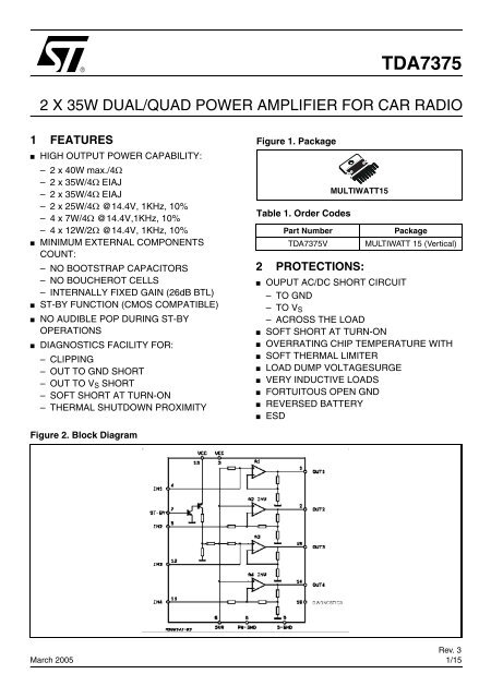
<strong>TDA7375</strong><br />
2 X 35W DUAL/QUAD POWER AMPLIFIER FOR CAR RADIO<br />
1 FEATURES<br />
■<br />
■<br />
■<br />
■<br />
■<br />
HIGH OUTPUT POWER CAPABILITY:<br />
– 2 x 40W max./4Ω<br />
– 2 x 35W/4Ω EIAJ<br />
– 2 x 35W/4Ω EIAJ<br />
– 2 x 25W/4Ω @14.4V, 1KHz, 10%<br />
– 4 x 7W/4Ω @14.4V,1KHz, 10%<br />
– 4 x 12W/2Ω @14.4V, 1KHz, 10%<br />
MINIMUM EXTERNAL COMPONENTS<br />
COUNT:<br />
– NO BOOTSTRAP CAPACITORS<br />
– NO BOUCHEROT CELLS<br />
– INTERNALLY FIXED GAIN (26dB BTL)<br />
ST-BY FUNCTION (CMOS COMPATIBLE)<br />
NO AUDIBLE POP DURING ST-BY<br />
OPERATIONS<br />
DIAGNOSTICS FACILITY FOR:<br />
– CLIPPING<br />
– OUT TO GND SHORT<br />
– OUT TO V S SHORT<br />
– SOFT SHORT AT TURN-ON<br />
– THERMAL SHUTDOWN PROXIMITY<br />
Figure 1. Package<br />
Table 1. Order Codes<br />
2 PROTECTIONS:<br />
■<br />
■<br />
■<br />
■<br />
■<br />
■<br />
■<br />
■<br />
■<br />
Part Number<br />
<strong>TDA7375</strong>V<br />
MULTIWATT15<br />
Package<br />
MULTIWATT 15 (Vertical)<br />
OUPUT AC/DC SHORT CIRCUIT<br />
– TO GND<br />
– TO V S<br />
– ACROSS THE LOAD<br />
SOFT SHORT AT TURN-ON<br />
OVERRATING CHIP TEMPERATURE WITH<br />
SOFT THERMAL LIMITER<br />
LOAD DUMP VOLTAGESURGE<br />
VERY INDUCTIVE LOADS<br />
FORTUITOUS OPEN GND<br />
REVERSED BATTERY<br />
ESD<br />
Figure 2. Block Diagram<br />
March 2005<br />
Rev. 3<br />
1/15
<strong>TDA7375</strong><br />
3 DESCRIPTION<br />
The <strong>TDA7375</strong> is a new technology class AB car radio amplifier able to work either in DUAL BRIDGE or<br />
QUAD SINGLE ENDED configuration.<br />
The exclusive fully complementary structure of the output stage and the internally fixed gain guarantees<br />
the highest possible power performances with extremely reduced component count.<br />
The on-board clip detector simplifies gain compression operation. The fault diagnostics makes it possible<br />
to detect mistakes during car radio set assembly and wiring in the car.<br />
Table 2. Absolute Maximum Ratings<br />
Symbol Parameter Value Unit<br />
V op Operating Supply Voltage 18 V<br />
V S DC Supply Voltage 28 V<br />
V peak Peak Supply Voltage (for t = 50ms) 50 V<br />
I O Output Peak Current (not repetitive t = 100µs) 4.5 A<br />
I O Output Peak Current (repetitive f > 10Hz) 3.5 A<br />
P tot Power Dissipation (T case = 85°C) 36 W<br />
T stg , T j Storage and Junction Temperature -40 to 150 °C<br />
Table 3. Thermal Data<br />
Symbol Parameter Value Unit<br />
R th j-case Thermal Resistance Junction-case max 1.8 °C/W<br />
Figure 3. Pin Connection (Top view)<br />
2/15
<strong>TDA7375</strong><br />
Table 4. Electrical Characteristcs (Refer to the test circuit, V S = 14.4V; R L = 4Ω; f = 1KHz; T amb = 25°C,<br />
unless otherwise specified)<br />
Symbol Parameter Test Condition Min. Typ. Max. Unit<br />
V S Supply Voltage Range 8 18 V<br />
I d Total Quiescent Drain Current R L = ∞ 150 mA<br />
V OS Output Offset Voltage 150 mV<br />
P O Output Power THD = 10%; R L = 4Ω<br />
Bridge<br />
Single Ended<br />
Single Ended, R L = 2Ω<br />
P O max Max. Output Power (***) V S = 14.4V, Bridge 36 40 W<br />
P O EIAJ EIAJ Output Power (***) V S = 13.7V, Bridge 32 35 W<br />
THD Distortion R L = 4Ω<br />
Single Ended, P O = 0.1 to 4W<br />
Bridge, P O = 0.1 to 10W<br />
(*) See built-in S/C protection description<br />
(**) Pin 10 Pulled-up to 5V with 10KΩ; R L = 4Ω<br />
(***) Saturated square wave output.<br />
23<br />
6.5<br />
25<br />
7<br />
12<br />
0.02<br />
0.03 0.3<br />
CT Cross Talk f = 1KHz Single Ended 70 dB<br />
f = 10KHz Single Ended 60 dB<br />
f = 1KHz Bridge 55 dB<br />
f = 10KHz Bridge 60 dB<br />
R IN Input Impedance Single Ended 20 30 KΩ<br />
Bridge 10 15 KΩ<br />
G V Voltage Gain Single Ended 19 20 21 dB<br />
Bridge 25 26 27 dB<br />
G V Voltage Gain Match 0.5 dB<br />
E IN Input Noise Voltage R g = 0; ”A” weighted, S.E.<br />
Non Inverting Channels<br />
Inverting Channels<br />
Bridge<br />
Rg = 0; 22Hz to 22KHz 3.5 µV<br />
SVR Supply Voltage Rejection R g = 0; f = 300Hz 50 dB<br />
A SB Stand-by Attenuation P O = 1W 80 90 dB<br />
I SB ST-BY Current Consumption V ST-BY = 0 to 1.5V 100 µA<br />
V SB ST-BY In Threshold Voltage 1.5 V<br />
V SB ST-BY Out Threshold Voltage 3.5 V<br />
I pin7 ST-BY Pin Current Play Mode V pin7 = 5V 50 µA<br />
Max Driving Curr. Under Fault (*) 5 mA<br />
I cd off Clipping Detector Output<br />
Average Current<br />
d = 1% (**) 90 µA<br />
Icd on Clipping Detector Output d = 5% (**) 160 µA<br />
Average Current<br />
V sat pin10 Voltage Saturation on pin 10 Sink Current at Pin 10 = 1mA 0.7 V<br />
2<br />
5<br />
W<br />
W<br />
W<br />
%<br />
%<br />
µV<br />
µV<br />
3/15
<strong>TDA7375</strong><br />
4 STANDARD TEST AND APPLICATION CIRCUIT<br />
Figure 4. Quad Stereo<br />
ST-BY<br />
10K R1<br />
C7<br />
10µF<br />
C6<br />
100nF<br />
V S<br />
C5<br />
1000µF<br />
Note:<br />
C9, C10, C11, C12 could be reduced<br />
if the 2W operation is not required.<br />
4 7 IN FL<br />
13 3<br />
1<br />
C1 0.22µF<br />
C10 2200µF<br />
IN FR 5<br />
2<br />
C2 0.22µF<br />
C9 2200µF<br />
IN RL<br />
12<br />
C4 0.22µF<br />
15<br />
IN RR 11<br />
C11 2200µF<br />
C3 0.22µF<br />
14<br />
6<br />
C8 47µF<br />
8 9 10 C12 2200µF<br />
DIAGNOSTICS<br />
D94AU063A<br />
OUT FL<br />
OUT FR<br />
OUT RL<br />
OUT RR<br />
Figure 5. Double Bridge<br />
ST-BY<br />
10K R1<br />
C5<br />
10µF<br />
C4<br />
100nF<br />
V S<br />
C3<br />
1000µF<br />
IN L<br />
13<br />
3<br />
1<br />
C1 0.47µF<br />
5<br />
OUT L<br />
IN R<br />
C2 0.47µF<br />
12<br />
11<br />
2<br />
15<br />
OUT R<br />
C8 47µF<br />
4 7 D94AU064A<br />
6<br />
8 9 10<br />
14<br />
DIAGNOSTICS<br />
Figure 6. Stereo/Bridge<br />
ST-BY<br />
10K<br />
10µF<br />
100nF<br />
VS<br />
1000µF<br />
4 7 13 3<br />
IN L<br />
1<br />
0.22µF<br />
2200µF<br />
IN L<br />
5<br />
2<br />
0.22µF<br />
2200µF<br />
IN BRIDGE 12<br />
15<br />
0.47µF 11<br />
6<br />
14<br />
8 9 10<br />
47µF<br />
DIAGNOSTICS<br />
D94AU065A<br />
OUT L<br />
OUT R<br />
OUT<br />
BRIDGE<br />
4/15
<strong>TDA7375</strong><br />
Figure 7. P.C. Board and Component Layout of the fig.4<br />
Figure 8. P.C. Board and Component Layout of the fig.5<br />
5/15
<strong>TDA7375</strong><br />
Figure 9. Quiescent Drain Current vs. Supply<br />
Voltage (Single Ended and Bridge).<br />
Figure 12. Output Power vs. Supply Voltage<br />
Figure 10. Quiescent Output Voltage vs.<br />
Supply Voltage (Single Ended and<br />
Bridge).<br />
Figure 13. OutputPower vs. Supply Voltage<br />
Figure 11. Output Power vs. Supply Voltage<br />
Figure 14. Distortion vs. Output Power<br />
6/15
<strong>TDA7375</strong><br />
Figure 15. Distortion vs. Output Power<br />
Figure 18. Supply Voltage Rejection vs.<br />
Frequency<br />
Figure 16. Distortion vs. Output Power<br />
Figure 19. Supply Voltage Rejection vs.<br />
Frequency<br />
Figure 17. Cross-talk vs. Frequency<br />
Figure 20. Stand-by Attenuation vs. Threshold<br />
Voltage<br />
7/15
<strong>TDA7375</strong><br />
Figure 21. Total Power Dissipation and<br />
Efficiency vs. Output Power<br />
Figure 22. Total Power Dissipation and<br />
Efficiency vs. Output Power<br />
5 GENERAL STRUCTURE<br />
5.1 High Application Flexibility<br />
The availability of 4 independent channels makes it possible to accomplish several kinds of applications<br />
ranging from 4 speakers stereo (F/R) to 2 speakers bridge solutions.<br />
In case of working in single ended conditions the polarity of the speakers driven by the inverting amplifier<br />
must be reversed respect to those driven by non inverting channels. This is to avoid phase inconveniences<br />
causing sound alterations especially during the reproduction of low frequencies.<br />
5.2 Easy Single Ended to Bridge Transition<br />
The change from single ended to bridge configurations is made simply by means of a short circuit across<br />
the inputs, that is no need of further external components.<br />
5.3 Gain Internally Fixed to 20dB in Single Ended, 26dB in Bridge<br />
Advantages of this design choice are in terms of:<br />
■ componentsand space saving<br />
■ output noise, supply voltage rejection and distortion optimization.<br />
5.4 Silent Turn On/Off and Muting/Stand-by Function<br />
The stand-by can be easily activated by means of a CMOS level applied to pin 7 through a RC filter.<br />
Under stand-by condition the device is turned off completely (supply current = 1µA typ.; output attenuation<br />
= 80dB min.). Every ON/OFF operation is virtually pop free. Furthemore, at turn-on the device stays in<br />
muting condition for a time determined by the value assigned to the SVR capacitor.<br />
While in muting the device outputs becomes insensitive to any kinds of signal that may be present at the<br />
input terminals. In other words every transient coming from previous stages produces no unplesantacoustic<br />
effect to the speakers.<br />
5.5 STAND-BY DRIVING (pin 7)<br />
Some precautions have to be taken in the definition of stand-by driving networks: pin 7 cannot be directly<br />
8/15
<strong>TDA7375</strong><br />
driven by a voltage source whose current capability is higher than 5mA. In practical cases a series resistance<br />
has always to be inserted, having it the double purpose of limiting the current at pin 7 and to smooth<br />
down the stand-by ON/OFF transitions - in combination with a capacitor - for output pop prevention.<br />
In any case, a capacitor of at least 100nF from pin 7 to S-GND, with no resistance in between, is necessary<br />
to ensure correct turn-on.<br />
5.6 OUTPUT STAGE<br />
The fully complementary output stage was made possible by the development of a new component: the<br />
ST exclusive power ICV PNP.<br />
A novel design based upon the connection shown in fig. 23 has then allowed the full exploitation of its possibilities.<br />
The clear advantagesthis new approach has over classical output stages are as follows:<br />
5.6.1 Rail-to-Rail Output Voltage Swing With No Need of Bootstrap Capacitors.<br />
The output swing is limited only by the V CEsat of the output transistors, which is in the range of 0.3Ω (R sat )<br />
each. Classical solutions adopting composite PNP-NPN for the upper output stage have higher saturation<br />
loss on the top side of the waveform.<br />
This unbalanced saturation causes a significant power reduction. The only way to recover power consists<br />
of the addition of expensive bootstrap capacitors.<br />
5.6.2 Absolute Stability Without Any External Compensation.<br />
Referring to the circuit of fig. 23 the gain V Out /V In is greater than unity, approximately 1+R2/R1. The DC<br />
output (V CC /2) is fixed by an auxiliary amplifier common to all the channels.<br />
By controlling the amount of this local feedbackit is possible to force the loop gain (A*β) to less than unity<br />
at frequency for which the phase shift is 180°. This means that the output buffer is intrinsically stableand<br />
not prone to oscillation.<br />
Most remarkably, the above feature has been achieved in spite of the very low closed loop gain of the<br />
amplifier. In contrast, with the classical PNP-NPN stage, the solution adopted for reducing the gain at high<br />
frequencies makes use of external RC networks, namely the Boucherot cells.<br />
5.7 BUILT–IN SHORTCIRCUIT PROTECTION<br />
Figure 23. The New Output Stage<br />
Reliable and safe operation, in presence of all kinds of short circuit involving the outputs is assured by<br />
BUILT-IN protectors. Additionally to the AC/DC short circuit to GND, to V S , across the speaker, a SOFT<br />
SHORT condition is signalled out during the TURN-ON PHASE so assuring correct operation for the de-<br />
9/15
<strong>TDA7375</strong><br />
vice itself and for the loudspeaker.<br />
This particular kind of protection acts in a way to avoid that the device is turned on (by ST-BY) when a<br />
resistive path (less than 16 ohms) is present between the output and GND. As the involved circuitry is normally<br />
disabled when a current higher than 5mA is flowing into the ST-BY pin, it is important, in order not<br />
to disable it, to have the external current source driving the ST-BY pin limited to 5mA.<br />
This extra function becomes particularly attractive when, in the single ended configuration, one capacitor<br />
is shared between two outputs (see fig. 24). Supposing that the output capacitor Cout for anyreason is<br />
shorted, the loudspeaker will not be damaged being this soft short circuit condition revealed.<br />
Figure 24.<br />
5.7.1 Diagnostics Facility<br />
The <strong>TDA7375</strong> is equipped with a diagnostic circuitry able to detect the following events:<br />
■<br />
■<br />
Clipping in the output signal<br />
Thermal shutdown<br />
■ Output fault:<br />
– short to GND<br />
– short to VS<br />
– soft short at turn on<br />
The information is available across an open collector output (pin 10) through a current sinking when the<br />
event is detected A current sinking at pin 10 is triggered when a certain distortion level is reached at any<br />
of the outputs. This function allows gain compression possibility whenever the amplifier is overdriven.<br />
5.7.2 Thermal Shutdown<br />
In this case the output 10 will signal the proximity of the junction temperature to the shutdown threshold.<br />
Typically current sinking at pin 10 will start ~10°C before the shutdown threshold is reached.<br />
Figure 25. Clipping Detection Waveforms<br />
10/15
<strong>TDA7375</strong><br />
Figure 26. Output Fault Waveforms (see fig. 27)<br />
Figure 27. Fault Waveforms<br />
5.8 HANDLING OF THE DIAGNOSTICS INFORMATION<br />
As various kinds of information is available at the same pin (clipping detection, output fault, thermal proximity),<br />
this signal must be handled properly in order to discriminate each event.<br />
This could be done by taking into account the different timing of the diagnostic output during each case.<br />
Normally the clip detector signalling produces a low level at pin 10 that is shorter than that present under<br />
faulty conditions; based on this assumption an interface circuitry to differentiate the information is represented<br />
in the schematic of fig. 29.<br />
11/15
<strong>TDA7375</strong><br />
Figure 28. Waveforms<br />
Figure 29.<br />
5.9 PCB-LAYOUT GROUNDING (general rules)<br />
The device has 2 distinct ground leads, P-GND (POWER GROUND) and S-GND (SIGNAL GROUND)<br />
which are practically disconnected from each other at chip level. Proper operation requires that P-GND<br />
and S-GND leads be connected together on the PCB-layout by means of reasonably low-resistance<br />
tracks.<br />
As for the PCB-ground configuration, a star-like arrangement whose center is represented by the supplyfiltering<br />
electrolytic capacitor ground is highly advisable. In such context, at least 2 separate paths have<br />
to be provided, one for P-GND and one for S-GND. The correct ground assignments are as follows:<br />
STANDBY CAPACITOR, pin 7 (or any other standby driving networks): on S-GND<br />
SVR CAPACITOR (pin 6): on S-GND and to be placed as close as possible to the device.<br />
INPUT SIGNAL GROUND (from active/passive signal processor stages): on S-GND.<br />
SUPPLY FILTERING CAPACITORS (pins 3,13): on P-GND.<br />
The (-) terminal of the electrolytic capacitor has to be directly tied to the battery (-) line and this should<br />
represent the starting point for all the ground paths.<br />
12/15
<strong>TDA7375</strong><br />
Figure 30. Multiwatt 15 Mechanical Data & Package Dimensions<br />
DIM.<br />
mm<br />
inch<br />
MIN. TYP. MAX. MIN. TYP. MAX.<br />
A5 0.197<br />
B 2.65 0.104<br />
C 1.6 0.063<br />
D 1 0.039<br />
E 0.49 0.55 0.019 0.022<br />
F 0.66 0.75 0.026 0.030<br />
G 1.02 1.27 1.52 0.040 0.050 0.060<br />
G1 17.53 17.78 18.03 0.690 0.700 0.710<br />
H1 19.6 0.772<br />
H2 20.2 0.795<br />
L 21.9 22.2 22.5 0.862 0.874 0.886<br />
L1 21.7 22.1 22.5 0.854 0.87 0.886<br />
L2 17.65 18.1 0.695 0.713<br />
L3 17.25 17.5 17.75 0.679 0.689 0.699<br />
L4 10.3 10.7 10.9 0.406 0.421 0.429<br />
L7 2.65 2.9 0.104 0.114<br />
M 4.25 4.55 4.85 0.167 0.179 0.191<br />
M1 4.73 5.08 5.43 0.186 0.200 0.214<br />
S 1.9 2.6 0.075 0.102<br />
S1 1.9 2.6 0.075 0.102<br />
Dia1 3.65 3.85 0.144 0.152<br />
OUTLINE AND<br />
MECHANICAL DATA<br />
Multiwatt15 (Vertical)<br />
0016036 J<br />
13/15
<strong>TDA7375</strong><br />
6 REVISION HISTORY<br />
Table 5. Revision History<br />
Date Revision Description of Changes<br />
July 2004 2 First Issue in EDOCS<br />
March 2005 3 Changed the Style-sheet in compliance to the new “Corporate Technical<br />
Pubblications Design Guide”.<br />
Deleted package Mukltiwatt15 Horizontal<br />
14/15
<strong>TDA7375</strong><br />
Information furnished is believed to be accurate and reliable. However, STMicroelectronics assumes no responsibility for the consequences<br />
of use of such information nor for any infringement of patents or other rights of third parties which may result from its use. No license is granted<br />
by implication or otherwise under any patent or patent rights of STMicroelectronics. Specifications mentioned in this publication are subject<br />
to change without notice. This publication supersedes and replaces all information previously supplied. STMicroelectronics products are not<br />
authorized for use as critical components in life support devices or systems without express written approval of STMicroelectronics.<br />
The ST logo is a registered trademark of STMicroelectronics.<br />
All other names are the property of their respective owners<br />
© 2005 STMicroelectronics - All rights reserved<br />
STMicroelectronics group of companies<br />
Australia - Belgium - Brazil - Canada - China - Czech Republic - Finland - France - Germany - Hong Kong - India - Israel - Italy - Japan -<br />
Malaysia - Malta - Morocco - Singapore - Spain - Sweden - Switzerland - United Kingdom - United States of America<br />
www.st.com<br />
15/15