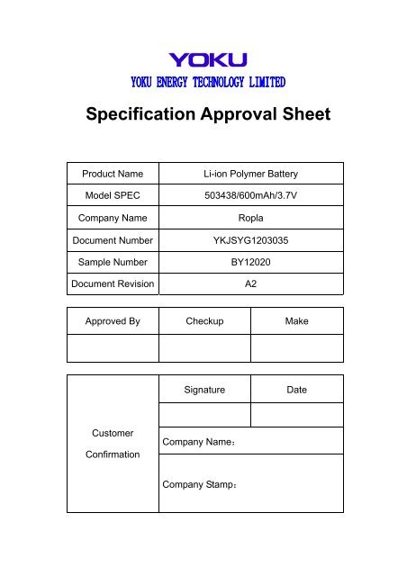
Specification Approval Sheet - Laro
Specification Approval Sheet - Laro
Specification Approval Sheet - Laro

Create successful ePaper yourself
Turn your PDF publications into a flip-book with our unique Google optimized e-Paper software.
<strong>Specification</strong> <strong>Approval</strong> <strong>Sheet</strong><br />
Product Name<br />
Model SPEC<br />
Company Name<br />
Document Number<br />
Sample Number<br />
Document Revision<br />
Li-ion Polymer Battery<br />
503438/600mAh/3.7V<br />
Ropla<br />
YKJSYG1203035<br />
BY12020<br />
A2<br />
Approved By Checkup Make<br />
Signature<br />
Date<br />
Customer<br />
Confirmation<br />
Company Name:<br />
Company Stamp:
<strong>Specification</strong> <strong>Approval</strong> <strong>Sheet</strong><br />
AMENDMENT RECORDS<br />
Modification<br />
Time<br />
Description Issued Date Approved By<br />
0 New release 2012-03-07<br />
1 Add the JS-1143R-04 2012-05-31<br />
2 Change the assemblage dimension 2012-6-29<br />
Page 2 of 16
<strong>Specification</strong> <strong>Approval</strong> <strong>Sheet</strong><br />
Content<br />
1. Scope ······························································································ 4<br />
2. Description ······················································································ 4<br />
3. <strong>Specification</strong> ···················································································· 4<br />
4. Battery Cell Performance Criteria···················································· 5<br />
5. Storage and others·········································································· 7<br />
6. Repair period··················································································· 7<br />
7. Assembly diagram··········································································· 8<br />
Handling Precautions and Guideline<br />
1. Charging························································································ 10<br />
2. Discharging Current ······································································ 10<br />
3. Discharging Temperature ······························································ 10<br />
4. Over-Discharge ··············································································11<br />
5. Protection Circuit Module(PCM)·····················································11<br />
6. Storage···························································································11<br />
7. Notice ·····························································································11<br />
8. Other Notice ·················································································· 12<br />
9. Recommended Notice··································································· 13<br />
▲Special Notice ················································································· 13<br />
Appendix<br />
Datasheet for Protection circuit module·············································· 14<br />
Any copies are invalid without our company’s approval<br />
Page 3 of 16
<strong>Specification</strong> <strong>Approval</strong> <strong>Sheet</strong><br />
1. Scope:<br />
This document is made according to customer parameter requirements,it describes the Product<br />
<strong>Specification</strong> of Chargeable Lithium Polymer Battery produced by Yoku Energy (Zhang zhou) Co.,<br />
Ltd.<br />
2. Description<br />
2.1 Model: 503438<br />
3. <strong>Specification</strong><br />
3.1 Assembled cell parameters<br />
No. Item Spec Note<br />
1 Model 503438/600mAh 1S<br />
2 Charge Voltage 4.2V<br />
3 Nominal Voltage 3.7V<br />
4 Nominal Capacity<br />
600mAh@ 0.2C<br />
Discharge<br />
Min: 582mAh<br />
5 Cycle Life ≥ 300 Times<br />
6 Impedance<br />
7 Max. Charge Current 0.5C<br />
8 Max. Discharge Current 1.0C<br />
9<br />
Discharge Cut-off<br />
Voltage<br />
10 Operating Temperature<br />
11<br />
long term storage<br />
temperature<br />
Cell Impedance:<br />
≤100mΩ<br />
Assemblage Impedance:<br />
≤250mΩ<br />
3.0V<br />
Discharge: -10℃~ +45℃<br />
Charge: 0℃~ +45℃<br />
-5 ℃ ~+ 35℃<br />
The average value of voltage during<br />
the discharge period (with standard<br />
charge and discharge). When<br />
shipping, the voltage without load is<br />
between 3.6V and 3.85V.<br />
Nominal Capacity refer to the<br />
capacity of 0.2C discharge to 2.75V<br />
cut-off voltage, after charging with<br />
standard method.<br />
One cycle refer to one charge period<br />
and then one discharge period.<br />
Test condition:<br />
Charge:0.2C to 4.2V<br />
Discharge: 0.2C to 2.75V<br />
The cycle life is the cycle times when<br />
the discharge capacity is about 75%<br />
of the rated capacity.<br />
After Standard charging, measure<br />
the internal resistance with AC1KHz<br />
(while measuring, clip near 2/3 place<br />
of the anode and the cathode.)<br />
Measure two sides of the drawing<br />
line after assembling. (Red B+ 、<br />
Black B-)<br />
Cells must be stored at 3.6V ~ 3.9V.<br />
Over long storage periods cells<br />
should be cycled every 90 days. The<br />
method is to do a charge-discharge<br />
cycle with standard method, then<br />
charge to 3.6V ~ 3.9V.<br />
Relative humidity: 45~75%RH<br />
Voltage:3.8±0.1V<br />
Page 4 of 16
<strong>Specification</strong> <strong>Approval</strong> <strong>Sheet</strong><br />
12 Cell Weight Approx: 11.8g<br />
13 PCM YK-ML76EM<br />
14 single cell Dimension<br />
15 Assemblage Dimension<br />
Length:38.5mm Max<br />
Width:34.5mm Max<br />
Thickness:5 mm Max<br />
Length:39.5mm Max<br />
Width:35mm Max<br />
Thickness:5.2mm Max<br />
Measured weight of 300gf at 25℃±<br />
1℃. Not including Tabs<br />
Measured weight of 300gf at 25℃±<br />
1℃.Not including battery drawing<br />
line.<br />
4. Battery Cell Performance Criteria<br />
4.1 Standard testing environment<br />
Unless specifically stated otherwise, tests must be done within one month of delivery and the<br />
number of charging-recharging cycles is fewer than 5. The following is test conditions:<br />
Test conditions:<br />
Ambient Temperature: 25ºC ± 1ºC<br />
Ambient Humidity: 45~75%RH<br />
4.2 The requirement of measure instrument<br />
(1) The measurement instrument has been certified by a qualified source.<br />
(2) The accuracy of the measuring instrument is less than 0.01mm.<br />
(3) The accuracy of multimeter is at least 0.5%. While measuring the voltage, the internal<br />
resistance can not be less than 10KΩ.<br />
(4) The principle internal resistance is 1KHz LCR; the accuracy is 0.2%.<br />
The internal resistance can vary based upon temperature and the charging mode. It is<br />
relevant to the PTC and the length and resistance of the wiring.<br />
(5) The current accuracy of the battery test system is at least ±0.1%, isobarically accuracy is<br />
±0.5%, and timer accuracy is not less than ±0.1%.<br />
(6) The accuracy of the thermometer is at least ±0.5ºC.<br />
4.3 Visual inspection<br />
Not allowing any visual defects which will affect the electronic characteristics, such as<br />
leakage and damage.<br />
4.4 Charge/Discharge Methods and Test Conditions<br />
No. Item Testing Conditions and Method<br />
1 Charging Current<br />
2<br />
3<br />
4<br />
5<br />
Low-temperature<br />
Charging<br />
(0℃~10℃)<br />
Standard<br />
Charging<br />
(0℃~45℃)<br />
Quick Charging<br />
(10℃~45℃)<br />
Standard<br />
Discharge<br />
Standard CC:0.2C<br />
Quick CC:0.5C<br />
Below 0.1C current charge from 2.75V to 4.2V, then CV to 0.05C<br />
cutoff, Then CV to 0.05C cutoff.<br />
Constant Current Charging at 0.2C to 4.2V.<br />
Constant Voltage Charging at 4.2V to cut-off current≤0.05C.<br />
Constant Current Charging at 0.5C to 4.2V. Constant Voltage<br />
Charging at 4.2V to cut-off current≤0.05C.<br />
Constant discharge at 0.2C to cut-off voltage of 2.75V.<br />
Page 5 of 16
<strong>Specification</strong> <strong>Approval</strong> <strong>Sheet</strong><br />
(-10℃~45℃)<br />
6 Charging Time<br />
7<br />
Temperature<br />
& Humidity<br />
Standard charging time :8 hours<br />
Quick charging time:2.8 hours<br />
Low-temperature Charging: 0ºC~ 10ºC 45~75% RH<br />
Standard charging: 0ºC~ 45ºC 45~75% RH<br />
Quick charging: 10ºC~ 45ºC 45~75%RH<br />
Standard discharging: -10ºC~ 45℃ 45~75% RH<br />
8 Cell Voltage 3.6~3.85V (Before shipping)<br />
4.5 Mechanical Characteristics<br />
No. Item Testing Conditions and Method Standard<br />
1 Vibration Test<br />
After standard charging, the cell is secured to<br />
a vibration table and subjected to vibration<br />
cycling in which the frequency is varied at the<br />
rate of 1Hz per minute between 10Hz and<br />
55Hz; the excursion of the vibration is<br />
0.38mm. The cell shall be vibrated for 30<br />
minutes on each of X, Y, and Z axis.<br />
No explosion, no fire<br />
A charged battery is dropped from a height of<br />
2 Drop Test<br />
No explosion, no fire<br />
1 meter two times onto a concrete surface.<br />
4.6 Safety Test<br />
No. Item Testing Conditions and Method Standard<br />
1 Over-charge<br />
2 Short-circuit<br />
3 Heat shock<br />
4<br />
Humidity<br />
and heat test<br />
After standard charging,the cell is conducted<br />
for 8 hours while the constant voltage is held<br />
at 4.5V and standard charging current flows<br />
through it.<br />
A charged battery is short-circuited for 1 hour<br />
at 0.04Ω.<br />
The cell is placed in a thermal chamber.<br />
Temperature is raised to 120±2ºC at the rate<br />
of (5±2ºC)/min and held for 10 minutes, then<br />
cooled to room temperature at the rate of<br />
5±2ºC/min.<br />
A charged battery is placed in a box for 48<br />
hours where the temperature is 40ºC±2ºC<br />
and the relative humidity is 90%~95%.<br />
No explosion, no fire<br />
No explosion, no fire<br />
No explosion, no fire<br />
No explosion, no fire<br />
4.7 High and low temperature test<br />
No. Item Testing Conditions and Method Standard<br />
1<br />
2<br />
High<br />
Temperature<br />
Low<br />
Temperature<br />
A charged battery is placed in an oven for 2<br />
hours at 55ºC±2ºC, then discharged at a<br />
0.5C current to the termination voltage.<br />
A charged battery is placed in a thermal<br />
chamber for 2 hours at -10ºC±2ºC; then<br />
discharged at 0.1C to the termination voltage.<br />
Discharge 90 percent of<br />
the original capacity.<br />
Discharge more than 45<br />
percent of the original<br />
capacity.<br />
Page 6 of 16
<strong>Specification</strong> <strong>Approval</strong> <strong>Sheet</strong><br />
4.8 Electricity maintenance<br />
No. Item Testing Conditions and Method Standard<br />
1<br />
Electricity<br />
maintenance<br />
A charged battery sits for 28 days at ambient<br />
temperature of 25ºC±1ºC, then discharged at<br />
a 0.2C current to the termination voltage.<br />
Discharge more than 85<br />
percent of the original<br />
capacity.<br />
5. Storage and others<br />
5.1 Long term Storage<br />
If the cell is to be stored for 3 months or longer it should be held in a dry and cool environment.<br />
Voltage during storage needs to me maintained between 3.6V~3.9V and the storage<br />
conditions are the same as Item 3.3.1.11<br />
5.2 Any issues not covered in this specification should be discussed between<br />
the customer and Yoku.<br />
6. Repair period<br />
The Repair period is 6 months from the data that the batteries are shipped out<br />
from YOKU factory (the printing date on the cell).<br />
Page 7 of 16
7.Drawing<br />
7.1 Assembly diagram(not to scale)<br />
Model:503438<br />
Unit:mm<br />
<strong>Specification</strong> <strong>Approval</strong> <strong>Sheet</strong><br />
UL1571 AWG30#<br />
P+/P- 150±2mm<br />
JS-1143R-04<br />
connector JS-1142-04<br />
UL1571 AWG30#<br />
P+/P- 150±2mm<br />
39.5mm Max<br />
P+(red)<br />
P-(black)<br />
+ -<br />
20120213000001<br />
600mAh 2.2V<br />
YOKU 503438 3.7V<br />
PCM YK-ML76EM<br />
white m ala tape<br />
transparent tape<br />
5.2mm Max<br />
35mm Max<br />
Page 8 of 16
7.2 Single cell Drawing(Not in scale)<br />
Model:503438<br />
Unit:mm<br />
<strong>Specification</strong> <strong>Approval</strong> <strong>Sheet</strong><br />
16±2mm<br />
10±1mm<br />
4±0.2mm<br />
4±0.2mm<br />
38mm Max<br />
2mm Max<br />
6mm Max<br />
34mm Max<br />
Page 9 of 16
<strong>Specification</strong> <strong>Approval</strong> <strong>Sheet</strong><br />
Handling Precaution and Guideline<br />
For LIP (Lithium-Ion Polymer) Rechargeable batteries<br />
Preface<br />
This document of ‘Handling Precautions and Guidelines for LIPO Rechargeable Batteries’<br />
shall be applied to the battery cells manufactured by Yoku Energy (Zhang zhou) Co., Ltd.<br />
Note (1): The customer is requested to contact YOKU in advance if and when the customer<br />
needs variations of the operating conditions described in this document. Additional<br />
experimentation may be required to verify performance and safety under such conditions.<br />
Note (2): YOKU will take no responsibility for any accident when the cell is used under<br />
conditions outside of this specification.<br />
Note (3): YOKU will inform the customer in writing of improvement(s) regarding proper use<br />
and handling of the cell if it is deemed necessary.<br />
Yoku Energy reserves the right to revise this specification before the customer signs the<br />
datasheet. If a revision is required, YOKU will notify the customer.<br />
1. Charging<br />
1.1 Charging Current:<br />
The charging current must be less than the maximum charge current specified in the<br />
<strong>Specification</strong> <strong>Approval</strong> <strong>Sheet</strong>.<br />
1.2 Charging Voltage:<br />
The charging voltage must be less than the maximum nominal voltage 4.2V, and the<br />
charging voltage upper limit is 4.30V (single pack).<br />
1.3 Charging Temperature:<br />
The cell must be charged within the range specified in this <strong>Specification</strong> <strong>Approval</strong> <strong>Sheet</strong>.<br />
1.4 Notes:<br />
Since charging is done with a constant current or a constant voltage, reverse charging is<br />
prohibited. If the cell is connected improperly it cannot be charged. Reverse charging<br />
can damage the cell and lead to degradation of cell performance, impair cell safety, and<br />
cause heat generation or leakage.<br />
2. Discharging Current:<br />
The cell shall be discharged at less than the maximum discharge current specified in the<br />
<strong>Specification</strong> <strong>Approval</strong> <strong>Sheet</strong>. A high discharging current may reduce the discharge<br />
capacity significantly or cause overheating.<br />
3. Discharging Temperature<br />
The Discharging Temperature must be within the range specified in this <strong>Specification</strong><br />
<strong>Approval</strong> <strong>Sheet</strong>.<br />
Page 10 of 16
<strong>Specification</strong> <strong>Approval</strong> <strong>Sheet</strong><br />
4. Over-Discharge<br />
Over-discharging will cause cell degradation and functional losses. The cell can degrade<br />
into an over-discharge state through self discharging. In order to prevent over-discharging,<br />
the cell should be charged periodically to retain between 3.6V and 3.9V.<br />
5. Protective Circuit Module<br />
5.1 The cell/battery pack shall contain a PCM that can protect the cell/<br />
battery pack properly.<br />
PCM shall have the following functions to ensure safety and prevent deterioration of cell<br />
performance:<br />
(1) overcharging prevention<br />
(2) over-discharging prevention<br />
(3) over current prevention.<br />
5.2 Overcharging Protection<br />
Overcharging prevention stops charging if any cell of the battery pack reaches 4.30V.<br />
5.3 Over-discharging protection<br />
The Over-discharging protection monitors the voltage of every cell in the pack and works<br />
to avoid a drop in the cell voltage to 2.8V or less.<br />
6. Storage<br />
Cells should be stored at the proper temperature that is identified in the <strong>Specification</strong><br />
<strong>Approval</strong> <strong>Sheet</strong>.<br />
7. Notice<br />
7.1 Handling of cells:<br />
★ Don’t charge the cells and keep them in a charged state for a long time.( Display units<br />
should dismantle the battery)<br />
★ Avoid any short-circuit. It will cause the leads to get hot and lose electronic functions.<br />
★ Soft package is easily damaged by sharp objects such as needles and knives. Avoid<br />
touching the cells with sharp objects when handling and storing.<br />
★ Next to the leads is the sealed edge. Don’t bend or fold the sealing edge as it is<br />
sensitive to movement.<br />
★ Don’t open the folded edge on the sides of the cell.<br />
★ Don’t bend the tabs as the tabs are sensitive.<br />
★ Avoid mechanical shock to the cells.<br />
★ Don’t put the cells into an oven, washing machine or any high-voltage container.<br />
★ Don’t use a charger without a safety certification. Use only a recommended charger.<br />
★ You should immediately stop charging if the cell overheats, emits an odor, changes<br />
color, changes shape, etc.<br />
★ Adults should supervise the use of batteries by children.<br />
★ Before using batteries, please carefully read and understand the handling guidelines.<br />
★ Avoid electro-static discharge when using, charging, and storing cells.<br />
★ Avoid putting the battery in contact with metal conductors such as neck chains,<br />
barrettes, or bolts, etc.<br />
★ Don’t use metal conductors to connect the positive and negative leads together.<br />
★ Avoid errors during assembly by contacting the positive lead with the negative lead.<br />
Page 11 of 16
<strong>Specification</strong> <strong>Approval</strong> <strong>Sheet</strong><br />
7.2 Notice for Designing Battery Pack<br />
7.2.1 Package Design<br />
1 The battery pack should have sufficient strength and the battery should be<br />
protected from mechanical shock.<br />
2 No sharp objects should be inside the pack containing the battery.<br />
7.2.2 PCM Design<br />
1 The overcharge threshold voltage should be less than 4.30V (single pack).<br />
2 The over-discharge threshold voltage should not be lower than 2.8V (single pack).<br />
3 The PCM should have short circuit protection.<br />
7.3 Notice for Assembling Battery Pack<br />
7.3.1 Tab connection<br />
1 Ultrasonic welding or spot welding is recommended to connect the battery with<br />
the PCM or other parts.<br />
2 If the tab is to be soldered to the PCM, the instructions below are very important to<br />
ensure battery performance.<br />
a) The solder iron should be temperature controlled and ESD safe.<br />
b) Soldering temperature should not exceed 350±10℃.<br />
c) Soldering time should not be longer than 3 seconds.<br />
d) Soldering times should not be fewer than 5.<br />
e) Let the battery tab cool down before soldering again.<br />
f) Direct heat to the cell body is strictly prohibited. The battery will be damaged<br />
by heat above approx. 60ºC.<br />
7.3.2 Cell fixing<br />
1 The cell should be fixed to the battery pack by its large surface area.<br />
2 There should be no sharp edges at the assembly contact area.<br />
3 Cells must be held firmly in the battery pack; movement is not allowed.<br />
4 The total thickness (the cell thickness plus the thickness of auxiliary materials,e.g.<br />
sponge pad, insulate pad, tape and so on) can't exceed the interior room of the<br />
plastic case, in order to prevent the cell from the damage and safe issue.<br />
8. Others<br />
8.1 Disassembly may cause an internal short circuit to the cell, which may cause out-gassing,<br />
fire, or other problems.<br />
8.2 LIP battery should not have liquid flowing, but in case the electrolyte come into contact<br />
with the skin, or eyes, physicians, we recommend as below:<br />
a. The electrolyte touch eyes: Flush the electrolyte immediately with fresh water for<br />
15min. and medical advice is to be sought.<br />
b. The electrolyte touch skin: Flush the electrolyte immediately with a great deal of<br />
fresh water.<br />
c. Breath the released gas: Go outside to breath flash air.<br />
d. Mis-eaten: Go to take some medical advice.<br />
8.3 Prohibition of dumping of cells into fire<br />
Never incinerate or dispose the cells in fire, for these may cause firing of the cells.<br />
8.4 The cells should never be soaked with liquids such as water, drinks or oil.<br />
8.5 Prohibit using the cells mixed with different manufactories. Prohibit using new cells mixed<br />
with old ones.<br />
8.6 Prohibit using damaged cells.<br />
Page 12 of 16
<strong>Specification</strong> <strong>Approval</strong> <strong>Sheet</strong><br />
9. Recommended Notice:<br />
9.1 Using cells on specified facilities only.<br />
9.2 Using cells in normal ambition temperature. Temperature: -10~35℃,Relative Humidity:<br />
45~75%.<br />
9.3 Using the cells, away from heat source. Don’t let children play with cells. Don’t drop cells.<br />
Charge cells with specified charger.<br />
9.4 Avoid the positive pole shortcutting with the negative one. Avoid the cells affected with<br />
damp.<br />
9.5 Useless cells should be deal with in a safety way. Don’t drop them into the water or fire.<br />
▲Special Notice: If the cell isn’t used for a long time, please keep the cells in a<br />
half-charged state neither fully charged and not completely discharged. Recharge the<br />
cells and use half of the power after 2-3 months. Store the cells in a cool and dry place.<br />
It will protect the cell from damage.<br />
Page 13 of 16
<strong>Specification</strong> <strong>Approval</strong> <strong>Sheet</strong><br />
Appendix<br />
Datasheet for Protection circuit module<br />
1 Electrical characteristics (YK-ML76EM)<br />
Item Symbol Content Criterion<br />
V DET1 Over charge detection voltage 4.275±0.02V<br />
Over charge<br />
Protection<br />
tV DET1 Over charge detection delay time<br />
0.8s-1.2s<br />
V REL1 Over charge release voltage 4.175±0.03V<br />
Over discharge<br />
protection<br />
V DET2 Over discharge detection voltage 3.0±0.035V<br />
tV DET2 Over discharge detection delay time<br />
100ms-150ms<br />
V DET3 Over current detection voltage 0.15±0.01V<br />
Over current<br />
protection<br />
I DP Over current detection current 2.0-5.0A<br />
tV DET3 Detection delay time 9.6ms-14.4ms<br />
Release condition<br />
Cut load<br />
Detection condition<br />
Exterior short circuit<br />
Short protection<br />
T SHORT Detection delay time 280us-560 us<br />
Release condition<br />
Cut short circuit<br />
Interior resistance R DS Main loop electrify resistance VC=4.2V,RDS≤60mΩ<br />
Current consumption<br />
I DD Current consume in normal operation 5.0μA Type 10.0μA Max<br />
Page 14 of 16
<strong>Specification</strong> <strong>Approval</strong> <strong>Sheet</strong><br />
2 Parts list<br />
NO. Location Part name <strong>Specification</strong><br />
Pack<br />
type<br />
Q’ty Maker/Remark<br />
1 U1<br />
Battery<br />
protection IC MM3028H01NRH SOT-23-6 1 MM ,<br />
or equivalent<br />
2 U2<br />
Silicon<br />
AOS ,<br />
AO8820/AO8822 TSSOP8 1<br />
MOSFET<br />
or equivalent<br />
3 R1 Resistance SMD 330Ω±5% 0402 1<br />
SKYWELL,<br />
Or equivalent<br />
4 R2 Resistance SMD 2.2KΩ±5% 0402 1<br />
SKYWELL ,<br />
or equivalent<br />
5 C1 Capacitance SMD 0.1μF /50V 0402 1<br />
SKYWELL,<br />
or equivalent<br />
6 PCB<br />
3 Application Circuit<br />
Print circuit<br />
board<br />
YK-ML76E<br />
18mm±0.2mm×<br />
4.0mm±0.2mm<br />
0.6mm±<br />
0.1mm<br />
1 ASSUN<br />
4 PCB layout<br />
top layer<br />
bottom layer<br />
Page 15 of 16
<strong>Specification</strong> <strong>Approval</strong> <strong>Sheet</strong><br />
top over view<br />
5 Terminal explanations<br />
B+:Connection cell +<br />
B-:Connection cell –<br />
P+:Connection output +<br />
P-:Connection output –<br />
6 LEAD-FREE Product<br />
Page 16 of 16