technical data
technical data
technical data

Create successful ePaper yourself
Turn your PDF publications into a flip-book with our unique Google optimized e-Paper software.
<strong>technical</strong> <strong>data</strong><br />
Systems<br />
FXAQ-MVE<br />
Wall mounted unit
• Wall mounted unit • FXAQ20-63MVE<br />
FXAQ-MVE 9<br />
Wall mounted unit 9<br />
1 Features......................................................................................................................................2<br />
2 Specifications<br />
Technical specifications....................................................................................................................................3<br />
Electrical specifications .....................................................................................................................................3<br />
Safety device settings .......................................................................................................................................4<br />
3 Accessories<br />
Drain pump kit ......................................................................................................................................................4<br />
4 Control systems.....................................................................................................................6<br />
5 Capacity tables<br />
Cooling capacity ...................................................................................................................................................7<br />
Heating capacity...................................................................................................................................................9<br />
6 Dimensions ............................................................................................................................11<br />
7 Piping Diagram ...................................................................................................................13<br />
8 Wiring Diagrams.................................................................................................................14<br />
9 Sound level............................................................................................................................15<br />
10 Installation<br />
Installation example........................................................................................................................................16<br />
Service space........................................................................................................................................................16<br />
Drain piping..........................................................................................................................................................17<br />
• Systems • Indoor Units 1
• Wall mounted unit • FXAQ20-63MVE<br />
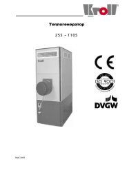
1 Features<br />
1-1 Lowest operation sound level in the industry<br />
• This super slim unit is stylish, unobtrusive and fits neatly on a wall<br />
• Auto-swing mechanism ensures efficient air distribution via louvers<br />
that close automatically when the unit is switched off<br />
• Comfortable air flow : the wide air discharge outlet distributes a<br />
comfortable air flow throughout the entire room<br />
• 5 different discharge angles can be programmed via the remote<br />
control<br />
• Very low sound pressure levels<br />
• Both horizontal flaps and front panel can be easily removed and<br />
washed<br />
• All maintenance operations can be carried out from the front of the<br />
unit<br />
• Drain-up pump with 1,000mm lift available as accessory<br />
Height of drain-up<br />
10°<br />
25°<br />
40° 55° 70°<br />
1.000mm<br />
• Discharge angle automatically returns to its previous position on<br />
restart (intial settings 10° for cooling and 70° for heating)<br />
Drain-up kit<br />
Indoor unit<br />
Drain-up kit<br />
10° Cooling<br />
70° Heating<br />
1<br />
2<br />
• Systems • Indoor Units
• Wall mounted unit • FXAQ20-63MVE<br />
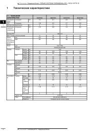
2 Specifications<br />
2-1 Technical specifications<br />
FXAQ-MVE 20 25 32 40 50 63<br />
COOLING CAPACITY (1) kW 2.2 2.8 3.6 4.5 5.6 7.1<br />
HEATING CAPACITY (2) kW 2.5 3.2 4.0 5.0 6.3 8.0<br />
NOMINAL INPUT Cooling W 16 22 27 20 27 50<br />
Heating W 24 27 32 20 32 60<br />
DIMENSIONS HxWxD mm 290x795x230 290x1,050x230<br />
WEIGHT kg 11 14<br />
COLOUR white (10Y9/0.5) white (B-272)<br />
SOUND LEVEL Sound pressure high dBA 35 36 37 39 42 46<br />
low dBA 29 29 29 34 36 39<br />
Sound power dBA * * * * * *<br />
FAN Air flow rate high m 3 /h 450 480 540 720 900 1,140<br />
low m 3 /h 270 300 330 540 720 840<br />
Type<br />
cross flow fan<br />
Motor output W 40 43<br />
Drive<br />
direct drive<br />
HEAT EXCHANGER Rows x stages x fin pitch mm 2x14x1.4<br />
Face area m 2 0.161<br />
AIR FILTER<br />
resin net (washable)<br />
REFRIGERANT CONTROL<br />
electronic expansion valve<br />
TEMPERATURE CONTROL<br />
microprocessor thermostat for cooling and heating<br />
PIPING CONNECTIONS Liquid flare mm ø 6.4 ø 9.5<br />
Gas flare mm ø 12.7 ø 15.9<br />
Drain mm VP13, external diameter 18, internal diameter 14<br />
Sound absorbing insulation material<br />
foamed polystyrene / foamed polyethylene<br />
3D039370<br />
NOTES<br />
1 Nominal cooling capacities are based on:<br />
• Indoor temperature: 27°CDB, 19°CWB<br />
• Outdoor temperature: 35°CDB<br />
• Equivalent refrigerant piping: 5m (horizontal)<br />
2 Nominal heating capacities are based on:<br />
• Indoor temperature: 20°CDB<br />
• Outdoor temperature: 7°CDB, 6°CWB<br />
• Equivalent refrigerant piping: 5m (horizontal)<br />
3 Capacities are net including a deduction for cooling (an addition for<br />
heating) for indoor fan motor heat.<br />
* <strong>data</strong> were not available at the time of publication<br />
2<br />
2-2 Electrical specifications<br />
FXAQ-MVE 20 25 32 40 50 63<br />
CURRENT Minimum circuit amps (MCA) A 0.3 0.4 0.4 0.4 0.4 0.6<br />
Maximum fuse amps (MFA) (5) A 15<br />
POWER SUPPLY V1 1 ~, 50Hz, 220-240V<br />
VOLTAGE RANGE Min~max V 198/264<br />
INDOOR FAN MOTOR Fan motor rated output W 40 43<br />
Full load amps (FLA) A 0.2 0.3 0.3 0.3 0.3 0.5<br />
4D034907B<br />
NOTES<br />
1 Voltage range: units are suitable for use on electrical systems where<br />
voltage supplied to unit terminals is not below or above listed range limits.<br />
2 Maximum allowable voltage range variation between phases is 2%.<br />
3 MCA/MFA:<br />
MCA = 1.25 x FLA<br />
MFA ≤ 4 x FLA<br />
next lower standard fuse rating minimum 15A.<br />
4 Select wire size based on the MCA.<br />
5 Instead of a fuse, use a circuit breaker<br />
6 For more details concerning conditional connections, see<br />
http://www.daikineurope.com/extranet, select "Daikin<br />
Documentation" and select "conditional connection", "the<br />
requested product type" and "English" from the drop down lists,<br />
click the search button.<br />
Finally, click on the document title of your choice.<br />
• Systems • Indoor Units 3
• Wall mounted unit • FXAQ20-63MVE<br />
2 Specifications<br />
2-3 Safety device settings<br />
FXAQ-MVE 20 25 32 40 50 63<br />
PC BOARD FUSE<br />
250V 5A<br />
4D034906A<br />
3 Accessories<br />
FXAQ-MVE 20 25 32 40 50 63<br />
DRAIN PUMP KIT<br />
K-KDU572BVE<br />
ED39-226<br />
3-1 Drain pump kit<br />
3-1-1 Specifications<br />
K-KDU572BVE<br />
DRAIN UP HEIGHT (1) mm 1,000<br />
DRAIN UP MECHANISM Power source 1 ~, 50-60Hz, 200V<br />
Power consumption W 12/11<br />
Insulation<br />
Type E<br />
DRAIN ENTRANCE CONNECTION PIPE DIAMETER<br />
VP20<br />
DRAIN EXIT CONNECTION PIPE DIAMETER<br />
VP20<br />
SAFETY DEVICE<br />
Float switch<br />
OPERATING NOISE dB 25<br />
WEIGHT kg 3.5<br />
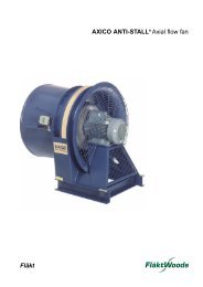
3-1-2 Dimensions and service space<br />
Position of hole in the ceiling (ø50)<br />
The drain pump kit can be installed to the left or the right of the air conditioner.<br />
The diagram below illustrates a left installation.<br />
2<br />
Max 1,000<br />
Vertical drain piping (VP20)<br />
(locally procured)<br />
Height should be set between 600 and<br />
1000. If set below 600, the operating<br />
noise of the pump may be a bit louder.<br />
Minimum downward slope: 1/100.<br />
Refrigerant piping<br />
Drain piping (VP20)<br />
(locally procured)<br />
at least 50mm<br />
Space needed<br />
for mounting<br />
at least<br />
Installation<br />
space<br />
Left and right installation possible<br />
Installation<br />
space<br />
4<br />
• Systems • Indoor Units
• Wall mounted unit • FXAQ20-63MVE<br />
3 Accessories<br />
3-1 Drain pump kit<br />
3-1-3 Wiring diagram<br />
Drain pump kit<br />
Drain pump mechanism<br />
Relay wire harness<br />
(accessory 2)<br />
Indoor unit<br />
Indoor p-board<br />
Float switch (safety)<br />
Timer<br />
Float switch (operation)<br />
(Locally procured)<br />
The earth wire (copper) should be at least 2.0 m 2 or ø1.6 mm.<br />
When the float switch (safety) is connected, remove the CN 15 short-circuit connector.<br />
Power cord<br />
3-1-4 Installation<br />
Caution<br />
• Exit piping parts must be procured locally.<br />
• Be sure to insulate the drain piping.<br />
• Give the horizontal sections on the drain piping a downward slope of<br />
at least 1/100 and make sure no air bubbles accumulate.<br />
• Secure long horizontal sections with support clamps to prevent them<br />
from shaking.<br />
When using centralised piping<br />
• Follow the figure below to make sure there is absolutely no back-up<br />
when using centralised piping.<br />
Max. 1m<br />
Take as much as possible<br />
downward slope (1/50-1/100)<br />
Use the biggest piping<br />
available<br />
Elbow (VP20) Insulation material<br />
(Locally procured (Locally procured)<br />
Vertical drain piping (VP20)<br />
(Locally procured<br />
Secured with adhesive<br />
Soft drain pipe<br />
(Accessory 14)<br />
Clamp<br />
(Accessory 8)<br />
Ceiling slab<br />
1-1.5m<br />
Horizontal drain piping (VP20)<br />
(min. downward slope 1/100)<br />
Support clamp<br />
2<br />
Insulation material<br />
(Accessory 6)<br />
• Systems • Indoor Units 5
• Wall mounted unit • FXAQ20-63MVE<br />
4 Control systems<br />
4-1 Individual control systems<br />
FXAQ-MVE 20 25 32 40 50 63<br />
WIRED REMOTE CONTROL<br />
BRC1D517<br />
INFRARED REMOTE CONTROL Heat pump BRC7E618<br />
Cooling only<br />
BRC7E619<br />
4-2 Centralised control systems<br />
CENTRALISED REMOTE CONTROL<br />
UNIFIED ON/OFF CONTROL<br />
SCHEDULE TIMER<br />
DCS302B51<br />
DCS301B51<br />
DST301B51<br />
4-3 Others<br />
WIRING ADAPTER FOR ELECTRICAL APPENDICES (1)<br />
WIRING ADAPTER FOR ELECTRICAL APPENDICES (2)<br />
INSTALLATION BOX FOR ADAPTER PCB (2) (3)<br />
REMOTE SENSOR<br />
ELECTRICAL BOX WITH EARTH TERMINAL (3 BLOCKS)<br />
ELECTRICAL BOX WITH EARTH TERMINAL (2 BLOCKS)<br />
NOISE FILTER (FOR ELECTROMAGNETIC INTERFACE USE ONLY)<br />
EXTERNAL CONTROL ADAPTER FOR OUTDOOR UNITS (INSTALLATION ON INDOOR UNIT)<br />
KRP2A51#<br />
KRP4A51#<br />
KRP4A93<br />
KRCS01-1<br />
KJB311A<br />
KJB212A<br />
KEK26-1<br />
DTA104A61#<br />
PCV0320<br />
NOTES<br />
1 Installation box is necessary for each adapter marked with #.<br />
2 Up to 2 adapters can be fixed per installation box.<br />
3 Only 1 installation box can be installed per indoor unit.<br />
4<br />
6<br />
• Systems • Indoor Units
• Wall mounted unit • FXAQ20-63MVE<br />
5 Capacity tables<br />
5-1 Cooling capacity<br />
Unit size<br />
Nominal<br />
capacity<br />
TC: Total capacity;kW – SHC: Sensible capacity;kW<br />
Indoor air temperature<br />
Outdoor<br />
14.0WB 16.0WB 18.0WB 19.0WB 20.0WB 22.0WB 24.0WB<br />
air temp.<br />
20.0DB 23.0DB 26.0DB 27.0DB 28.0DB 30.0DB 32.0DB<br />
°CDB TC SHC TC SHC TC SHC TC SHC TC SHC TC SHC TC SHC<br />
20 2.2 10.0 1.5 1.5 1.8 1.8 2.1 1.9 2.2 1.9 2.3 1.9 2.6 2.0 2.9 1.9<br />
12.0 1.5 1.5 1.8 1.8 2.1 1.9 2.2 1.9 2.3 1.9 2.6 2.0 2.9 1.9<br />
14.0 1.5 1.5 1.8 1.8 2.1 1.9 2.2 1.9 2.3 1.9 2.6 2.0 2.8 1.9<br />
16.0 1.5 1.5 1.8 1.8 2.1 1.9 2.2 1.9 2.3 1.9 2.6 2.0 2.8 1.9<br />
18.0 1.5 1.5 1.8 1.8 2.1 1.9 2.2 1.9 2.3 1.9 2.6 2.0 2.7 1.9<br />
20.0 1.5 1.5 1.8 1.8 2.1 1.9 2.2 1.9 2.3 1.9 2.6 2.0 2.7 1.9<br />
21.0 1.5 1.5 1.8 1.8 2.1 1.9 2.2 1.9 2.3 1.9 2.6 2.0 2.7 1.9<br />
23.0 1.5 1.5 1.8 1.8 2.1 1.9 2.2 1.9 2.3 1.9 2.6 1.9 2.6 1.9<br />
25.0 1.5 1.5 1.8 1.8 2.1 1.9 2.2 1.9 2.3 1.9 2.6 1.9 2.6 1.9<br />
27.0 1.5 1.5 1.8 1.8 2.1 1.9 2.2 1.9 2.3 1.9 2.5 1.9 2.6 1.8<br />
29.0 1.5 1.5 1.8 1.8 2.1 1.9 2.2 1.9 2.3 1.9 2.5 1.9 2.5 1.8<br />
31.0 1.5 1.5 1.8 1.8 2.1 1.9 2.2 1.9 2.3 1.9 2.4 1.9 2.5 1.8<br />
33.0 1.5 1.5 1.8 1.8 2.1 1.9 2.2 1.9 2.3 1.9 2.4 1.9 2.5 1.8<br />
35.0 1.5 1.5 1.8 1.8 2.1 1.9 2.2 1.9 2.3 1.9 2.4 1.9 2.4 1.8<br />
37.0 1.5 1.5 1.8 1.8 2.1 1.9 2.2 1.9 2.3 1.9 2.3 1.8 2.4 1.7<br />
39.0 1.5 1.5 1.8 1.8 2.1 1.9 2.2 1.9 2.2 1.9 2.3 1.8 2.3 1.7<br />
25 2.8 10.0 1.9 1.8 2.3 2.0 2.6 2.2 2.8 2.2 3.0 2.2 3.4 2.3 3.7 2.3<br />
12.0 1.9 1.8 2.3 2.0 2.6 2.2 2.8 2.2 3.0 2.2 3.4 2.3 3.6 2.2<br />
14.0 1.9 1.8 2.3 2.0 2.6 2.2 2.8 2.2 3.0 2.2 3.4 2.3 3.6 2.3<br />
16.0 1.9 1.8 2.3 2.0 2.6 2.2 2.8 2.2 3.0 2.2 3.4 2.3 3.5 2.2<br />
18.0 1.9 1.8 2.3 2.0 2.6 2.2 2.8 2.2 3.0 2.2 3.4 2.3 3.5 2.2<br />
20.0 1.9 1.8 2.3 2.0 2.6 2.2 2.8 2.2 3.0 2.2 3.4 2.3 3.4 2.2<br />
21.0 1.9 1.8 2.3 2.0 2.6 2.2 2.8 2.2 3.0 2.2 3.4 2.3 3.4 2.2<br />
23.0 1.9 1.8 2.3 2.0 2.6 2.2 2.8 2.2 3.0 2.2 3.3 2.3 3.4 2.2<br />
25.0 1.9 1.8 2.3 2.0 2.6 2.2 2.8 2.2 3.0 2.2 3.3 2.2 3.3 2.2<br />
27.0 1.9 1.8 2.3 2.0 2.6 2.2 2.8 2.2 3.0 2.2 3.2 2.2 3.3 2.1<br />
29.0 1.9 1.8 2.3 2.0 2.6 2.2 2.8 2.2 3.0 2.2 3.2 2.2 3.2 2.1<br />
31.0 1.9 1.8 2.3 2.0 2.6 2.2 2.8 2.2 3.0 2.2 3.1 2.2 3.2 2.1<br />
33.0 1.9 1.8 2.3 2.0 2.6 2.2 2.8 2.2 3.0 2.2 3.1 2.2 3.1 2.1<br />
35.0 1.9 1.8 2.3 2.0 2.6 2.2 2.8 2.2 3.0 2.2 3.0 2.2 3.1 2.1<br />
37.0 1.9 1.8 2.3 2.0 2.6 2.2 2.8 2.2 2.9 2.2 3.0 2.1 3.0 2.0<br />
39.0 1.9 1.8 2.3 2.0 2.6 2.2 2.8 2.2 2.9 2.2 2.9 2.1 3.0 2.0<br />
32 3.6 10.0 2.4 2.2 2.9 2.4 3.4 2.6 3.6 2.7 3.8 2.7 4.3 2.8 4.7 2.8<br />
12.0 2.4 2.2 2.9 2.4 3.4 2.6 3.6 2.7 3.8 2.7 4.3 2.8 4.7 2.8<br />
14.0 2.4 2.2 2.9 2.4 3.4 2.6 3.6 2.7 3.8 2.7 4.3 2.8 4.6 2.8<br />
16.0 2.4 2.2 2.9 2.4 3.4 2.6 3.6 2.7 3.8 2.7 4.3 2.8 4.6 2.8<br />
18.0 2.4 2.2 2.9 2.4 3.4 2.6 3.6 2.7 3.8 2.7 4.3 2.8 4.5 2.7<br />
20.0 2.4 2.2 2.9 2.4 3.4 2.6 3.6 2.7 3.8 2.7 4.3 2.8 4.4 2.7<br />
21.0 2.4 2.2 2.9 2.4 3.4 2.6 3.6 2.7 3.8 2.7 4.3 2.8 4.4 2.7<br />
23.0 2.4 2.2 2.9 2.4 3.4 2.6 3.6 2.7 3.8 2.7 4.2 2.8 4.3 2.7<br />
25.0 2.4 2.2 2.9 2.4 3.4 2.6 3.6 2.7 3.8 2.7 4.2 2.8 4.3 2.6<br />
27.0 2.4 2.2 2.9 2.4 3.4 2.6 3.6 2.7 3.8 2.7 4.1 2.7 4.2 2.6<br />
29.0 2.4 2.2 2.9 2.4 3.4 2.6 3.6 2.7 3.8 2.7 4.1 2.7 4.2 2.6<br />
31.0 2.4 2.2 2.9 2.4 3.4 2.6 3.6 2.7 3.8 2.7 4.0 2.7 4.1 2.6<br />
33.0 2.4 2.2 2.9 2.4 3.4 2.6 3.6 2.7 3.8 2.7 3.9 2.6 4.0 2.5<br />
35.0 2.4 2.2 2.9 2.4 3.4 2.6 3.6 2.7 3.8 2.7 3.9 2.6 4.0 2.5<br />
37.0 2.4 2.2 2.9 2.4 3.4 2.6 3.6 2.7 3.7 2.6 3.8 2.6 3.9 2.5<br />
39.0 2.4 2.2 2.9 2.4 3.4 2.6 3.6 2.7 3.7 2.6 3.8 2.6 3.8 2.5<br />
40 4.5 10.0 3.0 2.9 3.6 3.3 4.2 3.7 4.5 3.5 4.8 3.6 5.4 3.6 5.9 3.6<br />
12.0 3.0 2.9 3.6 3.3 4.2 3.7 4.5 3.5 4.8 3.6 5.4 3.6 5.8 3.5<br />
14.0 3.0 2.9 3.6 3.3 4.2 3.7 4.5 3.5 4.8 3.6 5.4 3.6 5.8 3.5<br />
16.0 3.0 2.9 3.6 3.3 4.2 3.7 4.5 3.5 4.8 3.6 5.4 3.6 5.7 3.5<br />
18.0 3.0 2.9 3.6 3.3 4.2 3.7 4.5 3.5 4.8 3.6 5.4 3.6 5.6 3.4<br />
20.0 3.0 2.9 3.6 3.3 4.2 3.7 4.5 3.5 4.8 3.6 5.4 3.6 5.5 3.4<br />
21.0 3.0 2.9 3.6 3.3 4.2 3.7 4.5 3.5 4.8 3.6 5.4 3.6 5.5 3.4<br />
23.0 3.0 2.9 3.6 3.3 4.2 3.7 4.5 3.5 4.8 3.6 5.3 3.6 5.4 3.3<br />
25.0 3.0 2.9 3.6 3.3 4.2 3.7 4.5 3.5 4.8 3.6 5.2 3.6 5.3 3.3<br />
27.0 3.0 2.9 3.6 3.3 4.2 3.7 4.5 3.5 4.8 3.6 5.2 3.5 5.3 3.3<br />
29.0 3.0 2.9 3.6 3.3 4.2 3.7 4.5 3.5 4.8 3.6 5.1 3.5 5.2 3.2<br />
31.0 3.0 2.9 3.6 3.3 4.2 3.7 4.5 3.5 4.8 3.6 5.0 3.4 5.1 3.2<br />
33.0 3.0 2.9 3.6 3.3 4.2 3.7 4.5 3.5 4.8 3.6 4.9 3.4 5.0 3.1<br />
35.0 3.0 2.9 3.6 3.3 4.2 3.7 4.5 3.5 4.7 3.6 4.9 3.4 5.0 3.1<br />
37.0 3.0 2.9 3.6 3.3 4.2 3.7 4.5 3.5 4.7 3.5 4.8 3.3 4.9 3.1<br />
39.0 3.0 2.9 3.6 3.3 4.2 3.7 4.5 3.5 4.6 3.5 4.7 3.3 4.8 3.0<br />
5<br />
• Systems • Indoor Units 7
• Wall mounted unit • FXAQ20-63MVE<br />
5 Capacity tables<br />
5-1 Cooling capacity<br />
5<br />
Unit size<br />
Nominal<br />
capacity<br />
TC: Total capacity;kW – SHC: Sensible capacity;kW<br />
Indoor air temperature<br />
Outdoor<br />
14.0WB 16.0WB 18.0WB 19.0WB 20.0WB 22.0WB 24.0WB<br />
air temp.<br />
20.0DB 23.0DB 26.0DB 27.0DB 28.0DB 30.0DB 32.0DB<br />
°CDB TC SHC TC SHC TC SHC TC SHC TC SHC TC SHC TC SHC<br />
50 5.6 10.0 3.8 3.2 4.5 3.7 5.2 4.1 5.6 4.2 6.0 4.3 6.7 4.4 7.4 4.4<br />
12.0 3.8 3.2 4.5 3.7 5.2 4.1 5.6 4.2 6.0 4.3 6.7 4.4 7.3 4.3<br />
14.0 3.8 3.2 4.5 3.7 5.2 4.1 5.6 4.2 6.0 4.3 6.7 4.4 7.2 4.3<br />
16.0 3.8 3.2 4.5 3.7 5.2 4.1 5.6 4.2 6.0 4.3 6.7 4.4 7.1 4.3<br />
18.0 3.8 3.2 4.5 3.7 5.2 4.1 5.6 4.2 6.0 4.3 6.7 4.4 7.0 4.2<br />
20.0 3.8 3.2 4.5 3.7 5.2 4.1 5.6 4.2 6.0 4.3 6.7 4.4 6.9 4.2<br />
21.0 3.8 3.2 4.5 3.7 5.2 4.1 5.6 4.2 6.0 4.3 6.7 4.4 6.8 4.2<br />
23.0 3.8 3.2 4.5 3.7 5.2 4.1 5.6 4.2 6.0 4.3 6.6 4.4 6.7 4.1<br />
25.0 3.8 3.2 4.5 3.7 5.2 4.1 5.6 4.2 6.0 4.3 6.5 4.3 6.6 4.1<br />
27.0 3.8 3.2 4.5 3.7 5.2 4.1 5.6 4.2 6.0 4.3 6.4 4.3 6.6 4.0<br />
29.0 3.8 3.2 4.5 3.7 5.2 4.1 5.6 4.2 6.0 4.3 6.3 4.2 6.5 4.0<br />
31.0 3.8 3.2 4.5 3.7 5.2 4.1 5.6 4.2 6.0 4.3 6.2 4.2 6.4 3.9<br />
33.0 3.8 3.2 4.5 3.7 5.2 4.1 5.6 4.2 6.0 4.3 6.1 4.2 6.3 3.9<br />
35.0 3.8 3.2 4.5 3.7 5.2 4.1 5.6 4.2 5.9 4.3 6.0 4.1 6.2 3.8<br />
37.0 3.8 3.2 4.5 3.7 5.2 4.1 5.6 4.2 5.8 4.3 5.9 4.1 6.1 3.8<br />
39.0 3.8 3.2 4.5 3.7 5.2 4.1 5.6 4.2 5.7 4.2 5.8 4.0 6.0 3.8<br />
63 7.1 10.0 4.8 4.1 5.7 4.6 6.6 5.1 7.1 5.3 7.6 5.4 8.5 5.6 9.3 5.3<br />
12.0 4.8 4.1 5.7 4.6 6.6 5.1 7.1 5.3 7.6 5.4 8.5 5.6 9.2 5.3<br />
14.0 4.8 4.1 5.7 4.6 6.6 5.1 7.1 5.3 7.6 5.4 8.5 5.6 9.1 5.2<br />
16.0 4.8 4.1 5.7 4.6 6.6 5.1 7.1 5.3 7.6 5.4 8.5 5.6 9.0 5.2<br />
18.0 4.8 4.1 5.7 4.6 6.6 5.1 7.1 5.3 7.6 5.4 8.5 5.6 8.8 5.2<br />
20.0 4.8 4.1 5.7 4.6 6.6 5.1 7.1 5.3 7.6 5.4 8.5 5.6 8.7 5.1<br />
21.0 4.8 4.1 5.7 4.6 6.6 5.1 7.1 5.3 7.6 5.4 8.5 5.6 8.7 5.1<br />
23.0 4.8 4.1 5.7 4.6 6.6 5.1 7.1 5.3 7.6 5.4 8.4 5.5 8.5 5.0<br />
25.0 4.8 4.1 5.7 4.6 6.6 5.1 7.1 5.3 7.6 5.4 8.3 5.5 8.4 5.0<br />
27.0 4.8 4.1 5.7 4.6 6.6 5.1 7.1 5.3 7.6 5.4 8.1 5.4 8.3 4.9<br />
29.0 4.8 4.1 5.7 4.6 6.6 5.1 7.1 5.3 7.6 5.4 8.0 5.4 8.2 4.9<br />
31.0 4.8 4.1 5.7 4.6 6.6 5.1 7.1 5.3 7.6 5.4 7.9 5.3 8.1 4.8<br />
33.0 4.8 4.1 5.7 4.6 6.6 5.1 7.1 5.3 7.6 5.4 7.8 5.2 7.9 4.8<br />
35.0 4.8 4.1 5.7 4.6 6.6 5.1 7.1 5.3 7.5 5.4 7.7 5.2 7.8 4.7<br />
37.0 4.8 4.1 5.7 4.6 6.6 5.1 7.1 5.3 7.4 5.3 7.5 5.1 7.7 4.7<br />
39.0 4.8 4.1 5.7 4.6 6.6 5.1 7.1 5.3 7.2 5.3 7.4 5.1 7.6 4.6<br />
8<br />
• Systems • Indoor Units
• Wall mounted unit • FXAQ20-63MVE<br />
5 Capacity tables<br />
5-2 Heating capacity<br />
Outdoor<br />
Indoor air temperature °CDB<br />
Unit Size Nominal capacity<br />
air temperature<br />
16.0 18.0 20.0 21.0 22.0 24.0<br />
°CDB °CWB kW kW kW kW kW kW<br />
20 2.5 -19.8 -20.0 1.5 1.5 1.5 1.5 1.5 1.5<br />
-18.8 -19.0 1.5 1.5 1.5 1.5 1.5 1.5<br />
-16.7 -17.0 1.6 1.6 1.6 1.6 1.6 1.6<br />
-14.7 -15.0 1.7 1.7 1.7 1.7 1.7 1.7<br />
-12.6 -13.0 1.8 1.8 1.8 1.8 1.8 1.8<br />
-10.5 -11.0 1.9 1.9 1.9 1.9 1.9 1.9<br />
-9.5 -10.0 1.9 1.9 1.9 1.9 1.9 1.9<br />
-8.5 -9.1 2.0 2.0 1.9 1.9 1.9 1.9<br />
-7.0 -7.6 2.0 2.0 2.0 2.0 2.0 2.0<br />
-5.0 -5.6 2.1 2.1 2.1 2.1 2.1 2.1<br />
-3.0 -3.7 2.2 2.2 2.2 2.2 2.2 2.2<br />
0.0 -0.7 2.3 2.3 2.3 2.3 2.3 2.2<br />
3.0 2.2 2.5 2.5 2.4 2.4 2.3 2.2<br />
5.0 4.1 2.5 2.5 2.5 2.4 2.3 2.2<br />
7.0 6.0 2.6 2.6 2.5 2.4 2.3 2.2<br />
9.0 7.9 2.7 2.7 2.5 2.4 2.3 2.2<br />
11.0 9.8 2.8 2.7 2.5 2.4 2.3 2.2<br />
13.0 11.8 2.8 2.7 2.5 2.4 2.3 2.2<br />
15.0 13.7 2.8 2.7 2.5 2.4 2.3 2.2<br />
25 3.2 -19.8 -20.0 1.9 1.9 1.9 1.9 1.9 1.9<br />
-18.8 -19.0 1.9 1.9 1.9 1.9 1.9 1.9<br />
-16.7 -17.0 2.1 2.1 2.0 2.0 2.0 2.0<br />
-14.7 -15.0 2.2 2.2 2.2 2.2 2.2 2.1<br />
-12.6 -13.0 2.3 2.3 2.3 2.3 2.3 2.3<br />
-10.5 -11.0 2.4 2.4 2.4 2.4 2.4 2.4<br />
-9.5 -10.0 2.5 2.4 2.4 2.4 2.4 2.4<br />
-8.5 -9.1 2.5 2.5 2.5 2.5 2.5 2.5<br />
-7.0 -7.6 2.6 2.6 2.6 2.6 2.6 2.6<br />
-5.0 -5.6 2.7 2.7 2.7 2.7 2.7 2.7<br />
-3.0 -3.7 2.8 2.8 2.8 2.8 2.8 2.8<br />
0.0 -0.7 3.0 3.0 3.0 3.0 3.0 2.8<br />
3.0 2.2 3.1 3.1 3.1 3.1 3.0 2.8<br />
5.0 4.1 3.3 3.2 3.2 3.1 3.0 2.8<br />
7.0 6.0 3.4 3.4 3.2 3.1 3.0 2.8<br />
9.0 7.9 3.5 3.4 3.2 3.1 3.0 2.8<br />
11.0 9.8 3.6 3.4 3.2 3.1 3.0 2.8<br />
13.0 11.8 3.6 3.4 3.2 3.1 3.0 2.8<br />
15.0 13.7 3.6 3.4 3.2 3.1 3.0 2.8<br />
32 4.0 -19.8 -20.0 2.4 2.4 2.3 2.3 2.3 2.3<br />
-18.8 -19.0 2.4 2.4 2.4 2.4 2.4 2.4<br />
-16.7 -17.0 2.6 2.6 2.6 2.6 2.6 2.5<br />
-14.7 -15.0 2.7 2.7 2.7 2.7 2.7 2.7<br />
-12.6 -13.0 2.9 2.8 2.8 2.8 2.8 2.8<br />
-10.5 -11.0 3.0 3.0 3.0 3.0 3.0 3.0<br />
-9.5 -10.0 3.1 3.1 3.1 3.1 3.0 3.0<br />
-8.5 -9.1 3.1 3.1 3.1 3.1 3.1 3.1<br />
-7.0 -7.6 3.2 3.2 3.2 3.2 3.2 3.2<br />
-5.0 -5.6 3.4 3.4 3.4 3.4 3.4 3.4<br />
-3.0 -3.7 3.5 3.5 3.5 3.5 3.5 3.5<br />
0.0 -0.7 3.7 3.7 3.7 3.7 3.7 3.5<br />
3.0 2.2 3.9 3.9 3.9 3.9 3.7 3.5<br />
5.0 4.1 4.1 4.1 4.0 3.9 3.7 3.5<br />
7.0 6.0 4.2 4.2 4.0 3.9 3.7 3.5<br />
9.0 7.9 4.3 4.3 4.0 3.9 3.7 3.5<br />
11.0 9.8 4.5 4.3 4.0 3.9 3.7 3.5<br />
13.0 11.8 4.5 4.3 4.0 3.9 3.7 3.5<br />
15.0 13.7 4.5 4.3 4.0 3.9 3.7 3.5<br />
40 5.0 -19.8 -20.0 3.0 2.9 2.9 2.9 2.9 2.9<br />
-18.8 -19.0 3.0 3.0 3.0 3.0 3.0 3.0<br />
-16.7 -17.0 3.2 3.2 3.2 3.2 3.2 3.2<br />
-14.7 -15.0 3.4 3.4 3.4 3.4 3.4 3.4<br />
-12.6 -13.0 3.6 3.6 3.6 3.5 3.5 3.5<br />
-10.5 -11.0 3.7 3.7 3.7 3.7 3.7 3.7<br />
-9.5 -10.0 3.8 3.8 3.8 3.8 3.8 3.8<br />
-8.5 -9.1 3.9 3.9 3.9 3.9 3.9 3.9<br />
-7.0 -7.6 4.0 4.0 4.0 4.0 4.0 4.0<br />
-5.0 -5.6 4.2 4.2 4.2 4.2 4.2 4.2<br />
-3.0 -3.7 4.4 4.4 4.4 4.4 4.4 4.4<br />
0.0 -0.7 4.7 4.6 4.6 4.6 4.6 4.4<br />
3.0 2.2 4.9 4.9 4.9 4.8 4.7 4.4<br />
5.0 4.1 5.1 5.1 5.0 4.8 4.7 4.4<br />
7.0 6.0 5.2 5.2 5.0 4.8 4.7 4.4<br />
9.0 7.9 5.4 5.3 5.0 4.8 4.7 4.4<br />
11.0 9.8 5.6 5.3 5.0 4.8 4.7 4.4<br />
13.0 11.8 5.6 5.3 5.0 4.8 4.7 4.4<br />
15.0 13.7 5.6 5.3 5.0 4.8 4.7 4.4<br />
5<br />
• Systems • Indoor Units 9
• Wall mounted unit • FXAQ20-63MVE<br />
5 Capacity tables<br />
5-2 Heating capacity<br />
5<br />
Outdoor<br />
Indoor air temperature °CDB<br />
Unit Size Nominal capacity<br />
air temperature<br />
16.0 18.0 20.0 21.0 22.0 24.0<br />
°CDB °CWB kW kW kW kW kW kW<br />
50 6.3 -19.8 -20.0 3.7 3.7 3.7 3.7 3.7 3.7<br />
-18.8 -19.0 3.8 3.8 3.8 3.8 3.8 3.8<br />
-16.7 -17.0 4.1 4.0 4.0 4.0 4.0 4.0<br />
-14.7 -15.0 4.3 4.3 4.3 4.2 4.2 4.2<br />
-12.6 -13.0 4.5 4.5 4.5 4.5 4.5 4.5<br />
-10.5 -11.0 4.7 4.7 4.7 4.7 4.7 4.7<br />
-9.5 -10.0 4.8 4.8 4.8 4.8 4.8 4.8<br />
-8.5 -9.1 4.9 4.9 4.9 4.9 4.9 4.9<br />
-7.0 -7.6 5.1 5.1 5.1 5.1 5.1 5.1<br />
-5.0 -5.6 5.3 5.3 5.3 5.3 5.3 5.3<br />
-3.0 -3.7 5.5 5.5 5.5 5.5 5.5 5.5<br />
0.0 -0.7 5.9 5.9 5.8 5.8 5.8 5.5<br />
3.0 2.2 6.2 6.2 6.2 6.1 5.9 5.5<br />
5.0 4.1 6.4 6.4 6.3 6.1 5.9 5.5<br />
7.0 6.0 6.6 6.6 6.3 6.1 5.9 5.5<br />
9.0 7.9 6.8 6.7 6.3 6.1 5.9 5.5<br />
11.0 9.8 7.0 6.7 6.3 6.1 5.9 5.5<br />
13.0 11.8 7.1 6.7 6.3 6.1 5.9 5.5<br />
15.0 13.7 7.1 6.7 6.3 6.1 5.9 5.5<br />
63 8.0 -19.8 -20.0 4.7 4.7 4.7 4.7 4.7 4.7<br />
-18.8 -19.0 4.9 4.9 4.8 4.8 4.8 4.8<br />
-16.7 -17.0 5.1 5.1 5.1 5.1 5.1 5.1<br />
-14.7 -15.0 5.4 5.4 5.4 5.4 5.4 5.4<br />
-12.6 -13.0 5.7 5.7 5.7 5.7 5.7 5.7<br />
-10.5 -11.0 6.0 6.0 6.0 6.0 6.0 5.9<br />
-9.5 -10.0 6.1 6.1 6.1 6.1 6.1 6.1<br />
-8.5 -9.1 6.3 6.3 6.2 6.2 6.2 6.2<br />
-7.0 -7.6 6.5 6.5 6.4 6.4 6.4 6.4<br />
-5.0 -5.6 6.8 6.7 6.7 6.7 6.7 6.7<br />
-3.0 -3.7 7.0 7.0 7.0 7.0 7.0 7.0<br />
0.0 -0.7 7.5 7.4 7.4 7.4 7.4 7.0<br />
3.0 2.2 7.9 7.8 7.8 7.7 7.5 7.0<br />
5.0 4.1 8.1 8.1 8.0 7.7 7.5 7.0<br />
7.0 6.0 8.4 8.4 8.0 7.7 7.5 7.0<br />
9.0 7.9 8.7 8.5 8.0 7.7 7.5 7.0<br />
11.0 9.8 8.9 8.5 8.0 7.7 7.5 7.0<br />
13.0 11.8 9.0 8.5 8.0 7.7 7.5 7.0<br />
15.0 13.7 9.0 8.5 8.0 7.7 7.5 7.0<br />
10<br />
• Systems • Indoor Units
• Wall mounted unit • FXAQ20-63MVE<br />
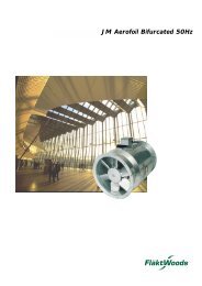
6 Dimensions<br />
FXAQ20-32MVE<br />
Piping direction<br />
Approx. 400<br />
232<br />
230<br />
90 or more<br />
(required space)<br />
290<br />
Dimensions for<br />
full open front panel<br />
50 or more<br />
(Required space)<br />
Outside line<br />
14.5<br />
Piping direction<br />
107<br />
155<br />
(Filter part)<br />
Name plate Note 2<br />
795<br />
626<br />
Approx. 475<br />
Approx. 460<br />
Piping direction<br />
62<br />
50 or more<br />
(Required space)<br />
30 or more<br />
(required space)<br />
2500 or more<br />
For installation<br />
in high places<br />
120 or less<br />
Nr Part name Description<br />
1 Front panel<br />
2 Front grill<br />
3 Air outlet<br />
4 Gas pipe ø 12.7 Flare connection<br />
5 Liquid pipe ø 6.4 Flare connection<br />
6 Drain hose VP13 (External dia. ø18)<br />
7 Grounding terminal M4<br />
8 Right side pipe connection hole<br />
9 Left side pipe connection hole<br />
105<br />
ø 80 hole<br />
44<br />
60<br />
125 Approx. 290<br />
(Filter part) (Flexible tube part)<br />
98<br />
Approx. 415 ø 80 hole<br />
(Piping and wiring intake)<br />
Mounting location<br />
44<br />
NOTES<br />
1 Name plate location: right side surface of casing<br />
2 In case of using an infrared remote control, this position will be<br />
a signal receiver. Refer to the drawing of an infrared remote<br />
control in detail.<br />
3D034903B<br />
FXAQ40,50MVE<br />
6<br />
Piping direction<br />
Approx. 400<br />
232<br />
230<br />
90 or more<br />
(required space)<br />
290<br />
Dimensions for<br />
full open front panel<br />
Outside line<br />
50 or more<br />
(Required space)<br />
104<br />
14.5<br />
Piping direction<br />
894<br />
155<br />
(Filter part)<br />
Name plate Note 2<br />
1,050<br />
Approx. 475<br />
Approx. 460<br />
Piping direction<br />
52<br />
30 or more<br />
(required space)<br />
2,500 or more<br />
50 or more For installation<br />
(Required space) in high places<br />
120 or less<br />
Nr Part name Description<br />
1 Front panel<br />
2 Front grill<br />
3 Air outlet<br />
4 Gas pipe ø 12.7 Flare connection<br />
5 Liquid pipe ø 6.4 Flare connection<br />
6 Drain hose VP13 (External dia. ø 18)<br />
7 Grounding terminal M4<br />
8 Right side pipe connection hole<br />
9 Left side pipe connection hole<br />
105<br />
ø 80 hole<br />
44<br />
60<br />
Mounting location<br />
125<br />
(Filter part)<br />
Approx. 290<br />
(Flexible tube part)<br />
98<br />
Approx. 415 ø 80 hole<br />
(Piping and wiring intake)<br />
44<br />
NOTES<br />
1 Name plate location: right side surface of casing.<br />
2 In case of using an infrared remote control, this position will be<br />
a signal receiver. Refer to the drawing of the infrared remote<br />
control in detail.<br />
3D038539A<br />
• Systems • Indoor Units 11
• Wall mounted unit • FXAQ20-63MVE<br />
6 Dimensions<br />
FXAQ63MVE<br />
Piping direction<br />
Approx. 400<br />
232<br />
230<br />
90 or more<br />
(required space)<br />
290<br />
Dimensions for<br />
full open front<br />
panel<br />
50 or more<br />
(Required space)<br />
Outside line<br />
14.5<br />
Piping direction<br />
104<br />
Name plate Note 2<br />
1,050<br />
894<br />
155<br />
(Filter part)<br />
Approx. 475<br />
Approx. 460<br />
Piping direction<br />
52<br />
50 or more<br />
(Required space)<br />
30 or more<br />
(required space)<br />
2,500 or more<br />
For installation<br />
in high places<br />
120 or less<br />
Nr Part name Description<br />
1 Front panel<br />
2 Front grill<br />
3 Air outlet<br />
4 Gas pipe ø 15.9 Flare connection<br />
5 Liquid pipe ø 9.5 Flare connection<br />
6 Drain hose VP13<br />
7 Grounding terminal M4<br />
8 Right side pipe connection hole<br />
9 Left side pipe connection hole<br />
105<br />
ø 80 hole<br />
44<br />
60<br />
125<br />
(Filter part) Approx. 415<br />
Mounting location<br />
44<br />
98<br />
ø 80 hole<br />
(Piping and wiring intake)<br />
NOTES<br />
1 Name plate location: right side surface of casing.<br />
2 In case of using an infrared remote control, this position will be<br />
a signal receiver. Refer to the drawing of the infrared remote<br />
control in detail.<br />
3D038541A<br />
6<br />
12<br />
• Systems • Indoor Units
• Wall mounted unit • FXAQ20-63MVE<br />
7 Piping Diagram<br />
FXAQ-MVE<br />
Heat exchanger<br />
Fan<br />
Liquid pipe connection port<br />
Filter<br />
Electronic<br />
expansion valve<br />
Filter<br />
Gas pipe connection port<br />
Refrigerant flow<br />
7<br />
Cooling<br />
Heating<br />
Piping connection diameters<br />
Model Gas Liquid<br />
FXAQ20,25,32,40,50MVE ø12.7 ø6.4<br />
FXAQ63MVE ø15.9 ø9.5<br />
Check valve<br />
Flare connection<br />
Screw connection<br />
Flange connection<br />
Pinched pipe<br />
Spinned pipe<br />
DU220-602D<br />
• Systems • Indoor Units 13
• Wall mounted unit • FXAQ20-63MVE<br />
8 Wiring Diagrams<br />
FXAQ-MVE<br />
Power supply<br />
220 - 240V 220V<br />
~ ~<br />
50Hz 60Hz<br />
5<br />
Note 5<br />
Receiver/display unit<br />
(Infrared remote control)<br />
Input from outside<br />
Transmission wiring<br />
Central remote controller<br />
Note 2<br />
Note 1<br />
Wired remote control<br />
Side<br />
Control Box<br />
(Indoor unit)<br />
Front<br />
A1P Printed circuit board Y1E Electronic expansion valve SS1 Selector switch (Main/sub)<br />
F1U Fuse ( , 250V, 3A) PC Power Circuit SS2 Selector switch (Wireless adress set)<br />
HAP Light emitting diode (Service monitor-green) Reciever/display unit (Attached to infrared remote control) Wired remote control<br />
M1A Motor (Swing flap) A2P Printed circuit board R1T Thermistor (Air)<br />
M1F Motor (Indoor fan) A3P Printed circuit board SS1 Selector switch (Main/sub)<br />
R1T Thermistor (Air) BS Push button (On/off) Connector for optional parts<br />
R2T Thermistor (Coil liquid pipe) H1P Light emitting dide (On-red) X15A Connector (Float switch)<br />
R3T Thermistor (Coil gas pipe) H2P Light emitting diode (Timer green) X35A Connector (Group control adapter)<br />
X1M Terminal strip (Control) H3P Light emitting diode (Filter sign-red)<br />
X2M Terminal strip (Power) H4P Light emitting diode (Defrost-orange)<br />
8<br />
: Field wiring<br />
: Terminal<br />
: Connector<br />
: Connector<br />
COLORS : RED : Red WHT : White YLW : Yellow<br />
BLK : Black BLU : Blue BRN : Brown<br />
PNK : Pink ORG : Orange GRN : Green<br />
NOTES<br />
1 In case of using centralised remote control, connect it to the unit in accordance with the attached installation manual.<br />
2 When connecting the input wires from outside, forced off or ON/OFF control operation can be selected by remote control. In details, refer to the installation manual atached the unit..<br />
3 Remote control model varies according to the combination system. Consult engeneering <strong>data</strong> and catalogues, etc.. before connecting.<br />
4 Confirm the method of setting the selector switch (SS1, SS2) of wired remote control and infrared remote control by installation manual and engineering <strong>data</strong>, etc.<br />
5 X24A is connected when the infrared remote control kit is being used.<br />
3D034206A<br />
14<br />
• Systems • Indoor Units
• Wall mounted unit • FXAQ20-63MVE<br />
9 Sound level<br />
9-1 Sound level <strong>data</strong><br />
Model<br />
Sound pressure level<br />
H L Measuring location<br />
Sound power level<br />
FXAQ20MVE 35 29 *<br />
FXAQ25MVE 36 29 *<br />
FXAQ32MVE 37 29 *<br />
FXAQ40MVE 39 34 *<br />
FXAQ50MVE 42 36 *<br />
FXAQ63MVE 46 39 Microphone<br />
*<br />
NOTES<br />
1 Reference acoustic pressure 0 dB = 20 Pa.<br />
2 Measuring place: anechoic chamber.<br />
3 Operating noise differs with operation and ambient conditions.<br />
*Data were not available at the time of publication<br />
9-2 Sound pressure spectrum<br />
FXAQ20MVE 4D037087 FXAQ25MVE 4D037088 FXAQ32MVE 4D037089<br />
Octave band sound pressure level dB (0dB = 0.0002µbar)<br />
Octave band sound pressure level dB (0dB = 0.0002µbar)<br />
Octave band sound pressure level dB (0dB = 0.0002µbar)<br />
Approximate<br />
threshold<br />
Approximate<br />
hearing for<br />
threshold<br />
Approximate<br />
continuous<br />
hearing for<br />
threshold<br />
noise<br />
continuous<br />
hearing for<br />
noise<br />
continuous<br />
noise<br />
Octave band center frequency (Hz)<br />
Octave band center frequency (Hz)<br />
Octave band center frequency (Hz)<br />
FXAQ40MVE 4D038513 FXAQ50MVE 4D038514 FXAQ63MVE 4D038515<br />
9<br />
Octave band sound pressure level dB (0dB = 0.0002µbar)<br />
Octave band sound pressure level dB (0dB = 0.0002µbar)<br />
Octave band sound pressure level dB (0dB = 0.0002µbar)<br />
Approximate<br />
threshold<br />
hearing for<br />
continuous<br />
noise<br />
Octave band center frequency (Hz)<br />
Approximate<br />
threshold<br />
hearing for<br />
continuous<br />
noise<br />
Octave band center frequency (Hz)<br />
Approximate<br />
threshold<br />
hearing for<br />
continuous<br />
noise<br />
Octave band center frequency (Hz)<br />
• Systems • Indoor Units 15
• Wall mounted unit • FXAQ20-63MVE<br />
10 Installation<br />
10-1 Installation example<br />
Air filter (Inside intake vent)<br />
Intake vent<br />
(front and top of main unit)<br />
Name plate<br />
(Indoor unit model name)<br />
Refrigerant pipe<br />
Interconnecting<br />
electric cable<br />
Drain pipe<br />
Remote control<br />
Air outlet<br />
Louver<br />
(horizontal fan direction adjustment flaps)<br />
Horizontal flaps<br />
(vertical fan direction adjustment flaps)<br />
Ground wire<br />
Provided to ground the<br />
indoor unit to prevent electric<br />
shock and ensure safety<br />
10-2 Service space<br />
10<br />
1 Select an installation site where the following conditions are fulfilled and that meets with your customer’s approval.<br />
• In the upper space (including the back of the ceiling) of the indoor unit where there is no possible dripping of water from the refrigerant pipe,<br />
drain pipe, water pipe, etc.<br />
• Where the wall is strong enough to bear the indoor unit weight.<br />
• Where sufficient clearance for installation and maintenance can be ensured.<br />
• Where optimum air distribution can be ensured.<br />
• Where nothing blocks the air passage.<br />
• Where condensation can be properly drained.<br />
• Where the wall is not significantly tilted.<br />
• Where not exposed to combustible gases.<br />
• Where piping between indoor and outdoor units is possible within the allowable limit. (Refer to the installation manual of the outdoor unit.)<br />
• Keep the indoor and outdoor units, power cable and transmission wiring, at least 1 m from TVs and radios, to prevent distorted pictures and<br />
static. (Depending on the type and source of the electrical waves, static may be heard even when more than 1 m away.)<br />
• Install the indoor unit no less than 2.5 m above the floor. Where unavoidably lower, take what measures are necessary to keep hands out of the<br />
air inlet.<br />
Space required for installation (mm)<br />
50 50<br />
90<br />
30<br />
Obstruction<br />
120<br />
2500 (from floor)<br />
for installation<br />
in high place.<br />
Floor<br />
2 Consider whether the location where the unit will be installed can support the full weight of the unit, and reinforce it with boards<br />
and beams, etc. if needed before proceeding with the installation. Also, reinforce the location to prevent vibration and noise before<br />
installing.<br />
3 The indoor unit may not be directly installed on the wall. Use the attached installation panel before installing the unit.<br />
16<br />
• Systems • Indoor Units
• Wall mounted unit • FXAQ20-63MVE<br />
10 Installation<br />
10-3 Drain piping<br />
1 Install the drain piping<br />
• The drain pipe should be short with a downward slope and should prevent the formation of air pockets.<br />
Make sure the drain hose is at a<br />
downward slope.<br />
Drain hose<br />
(Downward slope)<br />
Drain hose<br />
Make sure the tip does not go<br />
underwater even when water is added.<br />
• When extending the drain hose, use a commercially available drain extension hose, and be sure to insulate the extended section of the drain<br />
hose which is indoors.<br />
Indoor unit drain hose<br />
Extension drain piping (locally procured)<br />
Insulating tube (locally procured)<br />
Insulating tape (accessory)<br />
• Make sure the diameter of the piping is the same as the piping (hard vinyl chloride, nominal diameter 13mm) or bigger.<br />
• When directly connecting a hard vinyl chloride pipe joint (nominal diameter 13mm) to the drain hose connected to the indoor unit (i.e. for<br />
embedded piping, etc.), use a commercially available hard vinyl chloride pipe joint (nominal diameter 13mm).<br />
10<br />
Drain hose connected to the indoor unit<br />
Commercially available hard vinyl chloride pipe joint<br />
(nominal diameter 13mm)<br />
Commercially available hard vinyl chloride pipe (nominal<br />
diameter 13mm)<br />
• Systems • Indoor Units 17
• Wall mounted unit • FXAQ20-63MVE<br />
10<br />
18<br />
• Systems • Indoor Units
2<br />
Systems<br />
ISO14001 assures an effective environmental<br />
management system in order to help protect<br />
human health and the environment from the potential<br />
impact of our activities, products and services and to<br />
assist in maintaining and improving the quality of<br />
the environment.<br />
Daikin units comply with the European<br />
regulations that guarantee the safety of<br />
the product.<br />
Daikin Europe N.V. is approved by LRQA for its Quality<br />
Management System in accordance with the ISO9001<br />
standard. ISO9001 pertains to quality assurance regarding<br />
design, development, manufacturing as well as to services<br />
related to the product.<br />
VRV products are not within the scope<br />
of the Eurovent certification programme.<br />
Specifications are subject to change without prior notice<br />
Zandvoordestraat 300<br />
B-8400 Ostend - Belgium<br />
Internet: http://www.daikineurope.com<br />
EEDE03-2/3A • 08/2003<br />
Prepared in Belgium by Vanmelle