Create successful ePaper yourself
Turn your PDF publications into a flip-book with our unique Google optimized e-Paper software.
7 Wiring diagram<br />
7 - 1 Wiring diagram<br />
• Indoor Units • SLIM CONCEALED CEILING UNIT • <strong>FXDQ</strong>-<strong>PVE</strong> - <strong>FXDQ</strong>-<strong>NAVE</strong><br />
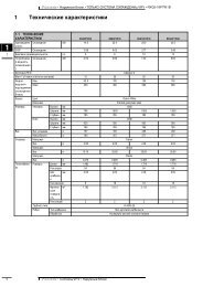
<strong>FXDQ</strong>20,25,32P - <strong>FXDQ</strong>40,50,63NA<br />
7<br />
Power supply<br />
220-240V<br />
~<br />
50Hz<br />
220V<br />
~<br />
60Hz<br />
Note 3<br />
Input from<br />
outside<br />
Transmission<br />
wiring central<br />
remote control<br />
Note 1<br />
Wired remote<br />
control<br />
Control box<br />
A1P Printed circuit board T1R Transformer (220V/22V)<br />
C1 Capacitor (M1F) V1TR Phase control circuit<br />
F1U Fuse (F5A/250V) X1M Terminal block<br />
HAP Light emitting diode (Service monitor-green) X2M Terminal block<br />
KPR Magnetic relay (M1P) Y1E Electronic expansion valve<br />
M1F Motor (Indoor fan) Z1C • Z2C Noise filter (Ferrity core)<br />
M1P Motor (Drain pump) Wired remote control<br />
Q1M Thermal protector (M1F embedded) T1T Thermistor (Air)<br />
R1T Thermistor (Air) SS1 Selector switch (Main/Sub)<br />
R2T Thermistor (Coil-1) Connector for optional parts<br />
R3T Thermistor (Coil-2) X16A Connector (Adaptor for wiring)<br />
S1L Float switch X18A Connector (Wiring adaptor for electrical appendices)<br />
: Terminal<br />
: Connector<br />
: Field wiring<br />
COLORS : BLK : Black BLU : Blue<br />
GRN : Green GRY : Grey<br />
ORG : Orange PNK : Pink<br />
PRP: Purple RED : Red<br />
WHT : White YLW : Yellow<br />
NOTES<br />
1 In case using central remote control, connect it to the unit in accordance with the attached installation manual<br />
2 Remote control model varies according to the combination system, confirm engineering materials and catalogs, etc. before connecting.<br />
3 When connecting the input wires from outside, forced off or on/off control operation can be selected by remote control. In details, refer to the installation manual attached the unit.<br />
3D045500C<br />
• VRV Systems • Indoor Units 15