
Create successful ePaper yourself
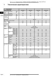
Turn your PDF publications into a flip-book with our unique Google optimized e-Paper software.
technical data<br />
Slim concealed ceiling unit<br />
<strong>FXDQ</strong>-<strong>PVE</strong> - <strong>FXDQ</strong>-<strong>NAVE</strong><br />
air conditioning systems
• Indoor Units • SLIM CONCEALED CEILING UNIT • <strong>FXDQ</strong>-<strong>PVE</strong> - <strong>FXDQ</strong>-<strong>NAVE</strong><br />
TABLE OF CONTENTS<br />
<strong>FXDQ</strong>-<strong>PVE</strong> - <strong>FXDQ</strong>-<strong>NAVE</strong><br />
1 Specifications . . . . . . . . . . . . . . . . . . . . . . . . . . . . . . . . . . . . . . . . . . . . . . . . . . . . . . . 2<br />
Technical Specifications . . . . . . . . . . . . . . . . . . . . . . . . . . . . . . . . . . . . . . . . . . . . . 2<br />
Electrical Specifications . . . . . . . . . . . . . . . . . . . . . . . . . . . . . . . . . . . . . . . . . . . . . 3<br />
2 Safety device settings . . . . . . . . . . . . . . . . . . . . . . . . . . . . . . . . . . . . . . . . . . . . . 4<br />
3 Control systems . . . . . . . . . . . . . . . . . . . . . . . . . . . . . . . . . . . . . . . . . . . . . . . . . . . . 5<br />
4 Capacity tables . . . . . . . . . . . . . . . . . . . . . . . . . . . . . . . . . . . . . . . . . . . . . . . . . . . . . 6<br />
Cooling capacity tables . . . . . . . . . . . . . . . . . . . . . . . . . . . . . . . . . . . . . . . . . . . . . . 6<br />
Heating capacity tables . . . . . . . . . . . . . . . . . . . . . . . . . . . . . . . . . . . . . . . . . . . . . . 8<br />
5 Dimensional drawing & centre of gravity . . . . . . . . . . . . . . . . . . . . . . . 10<br />
Dimensional drawing . . . . . . . . . . . . . . . . . . . . . . . . . . . . . . . . . . . . . . . . . . . . . . . . 10<br />
Centre of gravity . . . . . . . . . . . . . . . . . . . . . . . . . . . . . . . . . . . . . . . . . . . . . . . . . . . . 12<br />
6 Piping diagram . . . . . . . . . . . . . . . . . . . . . . . . . . . . . . . . . . . . . . . . . . . . . . . . . . . . . 14<br />
7 Wiring diagram. . . . . . . . . . . . . . . . . . . . . . . . . . . . . . . . . . . . . . . . . . . . . . . . . . . . . 15<br />
Wiring diagram . . . . . . . . . . . . . . . . . . . . . . . . . . . . . . . . . . . . . . . . . . . . . . . . . . . . . . 15<br />
8 Sound data . . . . . . . . . . . . . . . . . . . . . . . . . . . . . . . . . . . . . . . . . . . . . . . . . . . . . . . . . 16<br />
Sound pressure spectrum . . . . . . . . . . . . . . . . . . . . . . . . . . . . . . . . . . . . . . . . . . . 16<br />
9 Fan characteristics . . . . . . . . . . . . . . . . . . . . . . . . . . . . . . . . . . . . . . . . . . . . . . . . 18<br />
• VRV Systems • Indoor Units 1
at<br />
s e i c ne<br />
n t o s ry<br />
o-<br />
o id<br />
nl<br />
FI<br />
1 Specifications<br />
• Indoor Units • SLIM CONCEALED CEILING UNIT • <strong>FXDQ</strong>-<strong>PVE</strong> - <strong>FXDQ</strong>-<strong>NAVE</strong><br />
- m<br />
UE<br />
V C P S m Q DV<br />
XR<br />
VS<br />
1-1 TECHNICAL SPECIFICATIONS <strong>FXDQ</strong>20<strong>PVE</strong> <strong>FXDQ</strong>25<strong>PVE</strong> <strong>FXDQ</strong>32<strong>PVE</strong> <strong>FXDQ</strong>40<strong>NAVE</strong> <strong>FXDQ</strong>50<strong>NAVE</strong> <strong>FXDQ</strong>63<strong>NAVE</strong><br />
Nominal Cooling kW 2.20 2.80 3.60 4.50 5.60 7.10<br />
Capacity Heating kW 2.50 3.20 4.00 5.00 6.30 8.00<br />
Power input Cooling kW 0.086 0.086 0.089 0.160 0.165 0.181<br />
1<br />
(Nominal) Heating kW 0.067 0.067 0.070 0.147 0.152 0.168<br />
Casing Material Galvanised steel plate<br />
Dimensions Unit Height mm 200 200 200 200 200 200<br />
Width mm 700 700 700 900 900 1100<br />
Depth mm 620 620 620 620 620 620<br />
Weight Unit kg 23.0 23.0 23.0 27.0 28.0 31.0<br />
Heat<br />
Dimensions Nr of Rows 2 2 3 3 3 3<br />
Exchanger<br />
Fin Pitch mm 1.50 1.50 1.50 1.50 1.50 1.50<br />
Face m² 0.126 0.126 0.126 0.176 0.176 0.227<br />
Area<br />
Nr of Stages 12 12 12 12 12 12<br />
Fin Fin type Cross fin coil<br />
Fan Type Sirocco fan<br />
Quantity 1 1 1 1 1 1<br />
Air Flow Rate Cooling High m³/min 8.0 8.0 8.0 10.50 12.50 16.50<br />
Low m³/min 6.4 6.4 6.4 8.50 10.00 13.00<br />
Fan<br />
External static High Pa 30 30 30 44 44 44<br />
pressure Standard Pa 10 10 10 15 15 15<br />
Motor<br />
Output W 62 62 62 62 130 130<br />
(high)<br />
Drive<br />
Direct drive<br />
Refrigerant Name R-410A<br />
Cooling Sound<br />
High dBA 33.0 33.0 33.0 34.0 35.0 36.0<br />
Pressure Low dBA 29.0 29.0 29.0 30.0 31.0 32.0<br />
Piping<br />
Liquid (OD) Type Flare connection<br />
connections<br />
Diameter mm 6.4 6.4 6.4 6.4 6.4 9.5<br />
Gas Type Flare connection<br />
Diameter mm 12.7 12.7 12.7 12.7 12.7 15.9<br />
Drain Diameter mm VP20 (I.D. 20/O.D. 26)<br />
Air Filter<br />
Removable/washable/Mildew proof<br />
Refrigerant control<br />
Electronic expansion valve<br />
Temperature control<br />
Microprocessor thermostat for cooling and heating<br />
Safety devices<br />
Fuse<br />
Fan motor thermal protector<br />
Standard<br />
Accessories<br />
Standard Accessories<br />
Installation and operation manual<br />
Drain hose<br />
Sealing Pads<br />
Clamps<br />
Washer<br />
Insulation for fitting<br />
Clamp metal<br />
Washer fixing plate<br />
Screws for duct flanges<br />
Air filter<br />
Notes<br />
Nominal cooling capacities are based on : indoor temperature : 27°CDB, 19°CWB, outdoor temperature : 35°CDB,<br />
equivalent refrigerant piping : 7,5m (horizontal)<br />
Nominal heating capacities are based on : indoor temperature : 20°CDB, outdoor temperature : 7°CDB, 6°CWB,<br />
equivalent refrigerant piping : 7.5m (horizontal)<br />
Capacities are net, including a deduction for cooling (an addition for heating) for indoor fan motor heat.<br />
External static pressure can be changed by the remote control.<br />
The operation sound levels are conversion values in anechoic chamber. In practice, sound levels tend to be higher<br />
than the specified values due to ambient noise or reflection. When the suction place is changed to bottom suction,<br />
sound level will increase by approximately 5dBA.<br />
2<br />
• VRV Systems • Indoor Units
1 Specifications<br />
• Indoor Units • SLIM CONCEALED CEILING UNIT • <strong>FXDQ</strong>-<strong>PVE</strong> - <strong>FXDQ</strong>-<strong>NAVE</strong><br />
1-2 ELECTRICAL SPECIFICATIONS <strong>FXDQ</strong>20<strong>PVE</strong> <strong>FXDQ</strong>25<strong>PVE</strong> <strong>FXDQ</strong>32<strong>PVE</strong> <strong>FXDQ</strong>40<strong>NAVE</strong> <strong>FXDQ</strong>50<strong>NAVE</strong> <strong>FXDQ</strong>63<strong>NAVE</strong><br />
Power Supply Name VE<br />
Phase 1 1 1 1 1 1<br />
Frequency Hz 50 50 50 50 50 50<br />
Voltage V 220-240<br />
Current Minimum circuit amps A 0.80 0.80 0.80 1.00 1.00 1.10<br />
(MCA)<br />
Maximum fuse amps (MFA) A 15 15 15 15.00 15.00 15.00<br />
Full load amps (FLA) A 0.60 0.60 0.60 0.80 0.80 0.90<br />
Voltage range Minimum V -10%<br />
Maximum V +10%<br />
Notes<br />
Voltage range : units are suitable for use on electrical systems where voltage supplied to unit terminals is not below<br />
or above listed range limits.<br />
Maximum allowable voltage range variation between phases is 2%.<br />
MCA/MFA : MCA = 1.25 x FLA<br />
MFA
• Indoor Units • SLIM CONCEALED CEILING UNIT • <strong>FXDQ</strong>-<strong>PVE</strong> - <strong>FXDQ</strong>-<strong>NAVE</strong><br />
2 Safety device settings<br />
PC board (A1P) fuse<br />
Fan motor thermal protector<br />
<strong>FXDQ</strong>20P <strong>FXDQ</strong>25P <strong>FXDQ</strong>32P <strong>FXDQ</strong>40NA <strong>FXDQ</strong>50NA <strong>FXDQ</strong>63NA<br />
250V 5A<br />
OFF: 130 5C OFF<br />
ON: 83 15C ON<br />
2<br />
4D043861F<br />
4<br />
• VRV Systems • Indoor Units
• Indoor Units • SLIM CONCEALED CEILING UNIT • <strong>FXDQ</strong>-<strong>PVE</strong> - <strong>FXDQ</strong>-<strong>NAVE</strong><br />
3 Control systems<br />
Individual control systems<br />
<strong>FXDQ</strong>20P <strong>FXDQ</strong>25P <strong>FXDQ</strong>32P <strong>FXDQ</strong>40NA <strong>FXDQ</strong>50NA <strong>FXDQ</strong>63NA<br />
Wired remote control<br />
BRC1D52<br />
Infrared remote control H/P BRC4C62<br />
C/O<br />
BRC4C64<br />
Simplifide remote control<br />
BRC2A51<br />
Remote control for hotel use<br />
BRC3A61<br />
3<br />
Centralised control systems<br />
Central remote control<br />
Unified on/off control<br />
Schedule timer<br />
<strong>FXDQ</strong>20P <strong>FXDQ</strong>25P <strong>FXDQ</strong>32P <strong>FXDQ</strong>40NA <strong>FXDQ</strong>50NA <strong>FXDQ</strong>63NA<br />
DCS302C51<br />
DCS301B51<br />
DST301B51<br />
Others<br />
<strong>FXDQ</strong>20P <strong>FXDQ</strong>25P <strong>FXDQ</strong>32P <strong>FXDQ</strong>40NA <strong>FXDQ</strong>50NA <strong>FXDQ</strong>63NA<br />
Wiring adapter for electrical appendices (1)<br />
KRP2A53<br />
Wiring adapter for electrical appendices (2)<br />
KRP4A54<br />
Remote sensor<br />
KRCS01-1<br />
Installation box for adapter PCB<br />
KBP1B101<br />
Electrical box with earth terminal 2 blocks KJB212A<br />
3 blocks KJB311A<br />
Noise filter (for electromagnetic interface use only)<br />
KEK26-1A<br />
External control adapter for outdoor unit (must be installed on indoor units)<br />
DTA104A53<br />
4D045731C<br />
• VRV Systems • Indoor Units 5
4 Capacity tables<br />
4 - 1 Cooling capacity tables<br />
• Indoor Units • SLIM CONCEALED CEILING UNIT • <strong>FXDQ</strong>-<strong>PVE</strong> - <strong>FXDQ</strong>-<strong>NAVE</strong><br />
4<br />
<strong>FXDQ</strong>20,25,32P<br />
Unit size<br />
Nominal<br />
capacity<br />
TC: Total capacity;kW – SHC: Sensible capacity;kW<br />
Indoor air temperature<br />
Outdoor<br />
14.0WB 16.0WB 18.0WB 19.0WB 20.0WB 22.0WB 24.0WB<br />
air temp.<br />
20.0DB 23.0DB 26.0DB 27.0DB 28.0DB 30.0DB 32.0DB<br />
CDB TC SHC TC SHC TC SHC TC SHC TC SHC TC SHC TC SHC<br />
20 2.2 10.0 1.5 1.4 1.8 1.6 2.1 1.8 2.2 1.9 2.3 1.9 2.6 1.8 2.9 2.0<br />
12.0 1.5 1.4 1.8 1.6 2.1 1.8 2.2 1.9 2.3 1.9 2.6 1.8 2.9 2.0<br />
14.0 1.5 1.4 1.8 1.6 2.1 1.8 2.2 1.9 2.3 1.9 2.6 1.8 2.8 1.9<br />
16.0 1.5 1.4 1.8 1.6 2.1 1.8 2.2 1.9 2.3 1.9 2.6 1.8 2.8 1.9<br />
18.0 1.5 1.4 1.8 1.6 2.1 1.8 2.2 1.9 2.3 1.9 2.6 1.8 2.7 1.9<br />
20.0 1.5 1.4 1.8 1.6 2.1 1.8 2.2 1.9 2.3 1.9 2.6 1.8 2.7 1.9<br />
21.0 1.5 1.4 1.8 1.6 2.1 1.8 2.2 1.9 2.3 1.9 2.6 1.8 2.7 1.9<br />
23.0 1.5 1.4 1.8 1.6 2.1 1.8 2.2 1.9 2.3 1.9 2.6 1.8 2.6 1.9<br />
25.0 1.5 1.4 1.8 1.6 2.1 1.8 2.2 1.9 2.3 1.9 2.6 1.8 2.6 1.9<br />
27.0 1.5 1.4 1.8 1.6 2.1 1.8 2.2 1.9 2.3 1.9 2.5 1.8 2.6 1.9<br />
29.0 1.5 1.4 1.8 1.6 2.1 1.8 2.2 1.9 2.3 1.9 2.5 1.8 2.5 1.8<br />
31.0 1.5 1.4 1.8 1.6 2.1 1.8 2.2 1.9 2.3 1.9 2.4 1.7 2.5 1.8<br />
33.0 1.5 1.4 1.8 1.6 2.1 1.8 2.2 1.9 2.3 1.9 2.4 1.7 2.5 1.8<br />
35.0 1.5 1.4 1.8 1.6 2.1 1.8 2.2 1.9 2.3 1.9 2.4 1.7 2.4 1.8<br />
37.0 1.5 1.4 1.8 1.6 2.1 1.8 2.2 1.9 2.3 1.9 2.3 1.7 2.4 1.8<br />
39.0 1.5 1.4 1.8 1.6 2.1 1.8 2.2 1.9 2.2 1.9 2.3 1.6 2.3 1.8<br />
25 2.8 10.0 1.9 1.6 2.3 1.9 2.6 2.1 2.8 2.1 3.0 2.2 3.4 2.2 3.7 2.3<br />
12.0 1.9 1.6 2.3 1.9 2.6 2.1 2.8 2.1 3.0 2.2 3.4 2.2 3.6 2.2<br />
14.0 1.9 1.6 2.3 1.9 2.6 2.1 2.8 2.1 3.0 2.2 3.4 2.2 3.6 2.2<br />
16.0 1.9 1.6 2.3 1.9 2.6 2.1 2.8 2.1 3.0 2.2 3.4 2.2 3.5 2.2<br />
18.0 1.9 1.6 2.3 1.9 2.6 2.1 2.8 2.1 3.0 2.2 3.4 2.2 3.5 2.2<br />
20.0 1.9 1.6 2.3 1.9 2.6 2.1 2.8 2.1 3.0 2.2 3.4 2.2 3.4 2.2<br />
21.0 1.9 1.6 2.3 1.9 2.6 2.1 2.8 2.1 3.0 2.2 3.4 2.2 3.4 2.2<br />
23.0 1.9 1.6 2.3 1.9 2.6 2.1 2.8 2.1 3.0 2.2 3.3 2.2 3.4 2.1<br />
25.0 1.9 1.6 2.3 1.9 2.6 2.1 2.8 2.1 3.0 2.2 3.3 2.2 3.3 2.1<br />
27.0 1.9 1.6 2.3 1.9 2.6 2.1 2.8 2.1 3.0 2.2 3.2 2.2 3.3 2.1<br />
29.0 1.9 1.6 2.3 1.9 2.6 2.1 2.8 2.1 3.0 2.2 3.2 2.1 3.2 2.1<br />
31.0 1.9 1.6 2.3 1.9 2.6 2.1 2.8 2.1 3.0 2.2 3.1 2.1 3.2 2.1<br />
33.0 1.9 1.6 2.3 1.9 2.6 2.1 2.8 2.1 3.0 2.2 3.1 2.1 3.1 2.1<br />
35.0 1.9 1.6 2.3 1.9 2.6 2.1 2.8 2.1 3.0 2.2 3.0 2.1 3.1 2.0<br />
37.0 1.9 1.6 2.3 1.9 2.6 2.1 2.8 2.1 2.9 2.2 3.0 2.0 3.0 2.0<br />
39.0 1.9 1.6 2.3 1.9 2.6 2.1 2.8 2.1 2.9 2.1 2.9 2.0 3.0 2.0<br />
32 3.6 10.0 2.4 2.0 2.9 2.3 3.4 2.4 3.6 2.6 3.8 2.7 4.3 2.8 4.7 2.9<br />
12.0 2.4 2.0 2.9 2.3 3.4 2.4 3.6 2.6 3.8 2.7 4.3 2.8 4.7 2.9<br />
14.0 2.4 2.0 2.9 2.3 3.4 2.4 3.6 2.6 3.8 2.7 4.3 2.8 4.6 2.8<br />
16.0 2.4 2.0 2.9 2.3 3.4 2.4 3.6 2.6 3.8 2.7 4.3 2.8 4.6 2.8<br />
18.0 2.4 2.0 2.9 2.3 3.4 2.4 3.6 2.6 3.8 2.7 4.3 2.8 4.5 2.8<br />
20.0 2.4 2.0 2.9 2.3 3.4 2.4 3.6 2.6 3.8 2.7 4.3 2.8 4.4 2.8<br />
21.0 2.4 2.0 2.9 2.3 3.4 2.4 3.6 2.6 3.8 2.7 4.3 2.8 4.4 2.7<br />
23.0 2.4 2.0 2.9 2.3 3.4 2.4 3.6 2.6 3.8 2.7 4.2 2.8 4.3 2.7<br />
25.0 2.4 2.0 2.9 2.3 3.4 2.4 3.6 2.6 3.8 2.7 4.2 2.7 4.3 2.7<br />
27.0 2.4 2.0 2.9 2.3 3.4 2.4 3.6 2.6 3.8 2.7 4.1 2.7 4.2 2.7<br />
29.0 2.4 2.0 2.9 2.3 3.4 2.4 3.6 2.6 3.8 2.7 4.1 2.7 4.2 2.6<br />
31.0 2.4 2.0 2.9 2.3 3.4 2.4 3.6 2.6 3.8 2.7 4.0 2.6 4.1 2.6<br />
33.0 2.4 2.0 2.9 2.3 3.4 2.4 3.6 2.6 3.8 2.7 3.9 2.6 4.0 2.6<br />
35.0 2.4 2.0 2.9 2.3 3.4 2.4 3.6 2.6 3.8 2.7 3.9 2.6 4.0 2.5<br />
37.0 2.4 2.0 2.9 2.3 3.4 2.4 3.6 2.6 3.7 2.6 3.8 2.6 3.9 2.5<br />
39.0 2.4 2.0 2.9 2.3 3.4 2.4 3.6 2.6 3.7 2.6 3.8 2.5 3.8 2.5<br />
ED39226A<br />
6<br />
• VRV Systems • Indoor Units
4 Capacity tables<br />
4 - 1 Cooling capacity tables<br />
• Indoor Units • SLIM CONCEALED CEILING UNIT • <strong>FXDQ</strong>-<strong>PVE</strong> - <strong>FXDQ</strong>-<strong>NAVE</strong><br />
<strong>FXDQ</strong>40,50,63NA<br />
Unit size<br />
Nominal<br />
capacity<br />
TC: Total capacity;kW – SHC: Sensible capacity;kW<br />
Indoor air temperature<br />
Outdoor<br />
14.0WB 16.0WB 18.0WB 19.0WB 20.0WB 22.0WB 24.0WB<br />
air temp.<br />
20.0DB 23.0DB 26.0DB 27.0DB 28.0DB 30.0DB 32.0DB<br />
CDB TC SHC TC SHC TC SHC TC SHC TC SHC TC SHC TC SHC<br />
40 4.5 10.0 3.0 2.5 3.6 2.8 4.2 3.3 4.5 3.3 4.8 3.2 5.4 3.3 5.9 3.5<br />
12.0 3.0 2.5 3.6 2.8 4.2 3.3 4.5 3.3 4.8 3.2 5.4 3.3 5.8 3.5<br />
14.0 3.0 2.5 3.6 2.8 4.2 3.3 4.5 3.3 4.8 3.2 5.4 3.3 5.8 3.5<br />
16.0 3.0 2.5 3.6 2.8 4.2 3.3 4.5 3.3 4.8 3.2 5.4 3.3 5.7 3.5<br />
18.0 3.0 2.5 3.6 2.8 4.2 3.3 4.5 3.3 4.8 3.2 5.4 3.3 5.6 3.4<br />
20.0 3.0 2.5 3.6 2.8 4.2 3.3 4.5 3.3 4.8 3.2 5.4 3.3 5.5 3.4<br />
21.0 3.0 2.5 3.6 2.8 4.2 3.3 4.5 3.3 4.8 3.2 5.4 3.3 5.5 3.4<br />
23.0 3.0 2.5 3.6 2.8 4.2 3.3 4.5 3.3 4.8 3.2 5.3 3.3 5.4 3.3<br />
25.0 3.0 2.5 3.6 2.8 4.2 3.3 4.5 3.3 4.8 3.2 5.2 3.3 5.3 3.3<br />
27.0 3.0 2.5 3.6 2.8 4.2 3.3 4.5 3.3 4.8 3.2 5.2 3.2 5.3 3.3<br />
29.0 3.0 2.5 3.6 2.8 4.2 3.3 4.5 3.3 4.8 3.2 5.1 3.2 5.2 3.3<br />
31.0 3.0 2.5 3.6 2.8 4.2 3.3 4.5 3.3 4.8 3.2 5.0 3.2 5.1 3.2<br />
33.0 3.0 2.5 3.6 2.8 4.2 3.3 4.5 3.3 4.8 3.2 4.9 3.2 5.0 3.2<br />
35.0 3.0 2.5 3.6 2.8 4.2 3.3 4.5 3.3 4.7 3.2 4.9 3.1 5.0 3.2<br />
37.0 3.0 2.5 3.6 2.8 4.2 3.3 4.5 3.3 4.7 3.2 4.8 3.1 4.9 3.1<br />
39.0 3.0 2.5 3.6 2.8 4.2 3.3 4.5 3.3 4.6 3.2 4.7 3.1 4.8 3.1<br />
50 5.6 10.0 3.8 3.1 4.5 3.5 5.2 3.9 5.6 4.0 6.0 4.0 6.7 4.2 7.4 4.1<br />
12.0 3.8 3.1 4.5 3.5 5.2 3.9 5.6 4.0 6.0 4.0 6.7 4.2 7.3 4.1<br />
14.0 3.8 3.1 4.5 3.5 5.2 3.9 5.6 4.0 6.0 4.0 6.7 4.2 7.2 4.1<br />
16.0 3.8 3.1 4.5 3.5 5.2 3.9 5.6 4.0 6.0 4.0 6.7 4.2 7.1 4.0<br />
18.0 3.8 3.1 4.5 3.5 5.2 3.9 5.6 4.0 6.0 4.0 6.7 4.2 7.0 4.0<br />
20.0 3.8 3.1 4.5 3.5 5.2 3.9 5.6 4.0 6.0 4.0 6.7 4.2 6.9 4.0<br />
21.0 3.8 3.1 4.5 3.5 5.2 3.9 5.6 4.0 6.0 4.0 6.7 4.2 6.8 4.0<br />
23.0 3.8 3.1 4.5 3.5 5.2 3.9 5.6 4.0 6.0 4.0 6.6 4.2 6.7 3.9<br />
25.0 3.8 3.1 4.5 3.5 5.2 3.9 5.6 4.0 6.0 4.0 6.5 4.1 6.6 3.9<br />
27.0 3.8 3.1 4.5 3.5 5.2 3.9 5.6 4.0 6.0 4.0 6.4 4.1 6.6 3.9<br />
29.0 3.8 3.1 4.5 3.5 5.2 3.9 5.6 4.0 6.0 4.0 6.3 4.0 6.5 3.8<br />
31.0 3.8 3.1 4.5 3.5 5.2 3.9 5.6 4.0 6.0 4.0 6.2 4.0 6.4 3.8<br />
33.0 3.8 3.1 4.5 3.5 5.2 3.9 5.6 4.0 6.0 4.0 6.1 4.0 6.3 3.8<br />
35.0 3.8 3.1 4.5 3.5 5.2 3.9 5.6 4.0 5.9 4.0 6.0 3.9 6.2 3.7<br />
37.0 3.8 3.1 4.5 3.5 5.2 3.9 5.6 4.0 5.8 4.0 5.9 3.9 6.1 3.7<br />
39.0 3.8 3.1 4.5 3.5 5.2 3.9 5.6 4.0 5.7 3.9 5.8 3.9 6.0 3.7<br />
63 7.1 10.0 4.8 3.8 5.7 4.3 6.6 4.8 7.1 4.9 7.6 4.9 8.5 5.1 9.3 5.7<br />
12.0 4.8 3.8 5.7 4.3 6.6 4.8 7.1 4.9 7.6 4.9 8.5 5.1 9.2 5.6<br />
14.0 4.8 3.8 5.7 4.3 6.6 4.8 7.1 4.9 7.6 4.9 8.5 5.1 9.1 5.5<br />
16.0 4.8 3.8 5.7 4.3 6.6 4.8 7.1 4.9 7.6 4.9 8.5 5.1 9.0 5.4<br />
18.0 4.8 3.8 5.7 4.3 6.6 4.8 7.1 4.9 7.6 4.9 8.5 5.1 8.8 5.4<br />
20.0 4.8 3.8 5.7 4.3 6.6 4.8 7.1 4.9 7.6 4.9 8.5 5.1 8.7 5.3<br />
21.0 4.8 3.8 5.7 4.3 6.6 4.8 7.1 4.9 7.6 4.9 8.5 5.1 8.7 5.3<br />
23.0 4.8 3.8 5.7 4.3 6.6 4.8 7.1 4.9 7.6 4.9 8.4 5.1 8.5 5.2<br />
25.0 4.8 3.8 5.7 4.3 6.6 4.8 7.1 4.9 7.6 4.9 8.3 5.0 8.4 5.1<br />
27.0 4.8 3.8 5.7 4.3 6.6 4.8 7.1 4.9 7.6 4.9 8.1 5.0 8.3 5.1<br />
29.0 4.8 3.8 5.7 4.3 6.6 4.8 7.1 4.9 7.6 4.9 8.0 4.9 8.2 5.0<br />
31.0 4.8 3.8 5.7 4.3 6.6 4.8 7.1 4.9 7.6 4.9 7.9 4.9 8.1 4.9<br />
33.0 4.8 3.8 5.7 4.3 6.6 4.8 7.1 4.9 7.6 4.9 7.8 4.8 7.9 4.9<br />
35.0 4.8 3.8 5.7 4.3 6.6 4.8 7.1 4.9 7.5 4.8 7.7 4.8 7.8 4.8<br />
37.0 4.8 3.8 5.7 4.3 6.6 4.8 7.1 4.9 7.4 4.8 7.5 4.7 7.7 4.8<br />
39.0 4.8 3.8 5.7 4.3 6.6 4.8 7.1 4.9 7.2 4.7 7.4 4.7 7.6 4.7<br />
ED39226A<br />
4<br />
• VRV Systems • Indoor Units 7
4 Capacity tables<br />
4 - 2 Heating capacity tables<br />
<strong>FXDQ</strong>20,25,32P<br />
• Indoor Units • SLIM CONCEALED CEILING UNIT • <strong>FXDQ</strong>-<strong>PVE</strong> - <strong>FXDQ</strong>-<strong>NAVE</strong><br />
4<br />
Outdoor<br />
Indoor air temperature CDB<br />
Unit Size Nominal capacity<br />
air temperature<br />
16.0 18.0 20.0 21.0 22.0 24.0<br />
CDB CWB kW kW kW kW kW kW<br />
20 2.5 -19.8 -20.0 1.5 1.5 1.5 1.5 1.5 1.5<br />
-18.8 -19.0 1.5 1.5 1.5 1.5 1.5 1.5<br />
-16.7 -17.0 1.6 1.6 1.6 1.6 1.6 1.6<br />
-14.7 -15.0 1.7 1.7 1.7 1.7 1.7 1.7<br />
-12.6 -13.0 1.8 1.8 1.8 1.8 1.8 1.8<br />
-10.5 -11.0 1.9 1.9 1.9 1.9 1.9 1.9<br />
-9.5 -10.0 1.9 1.9 1.9 1.9 1.9 1.9<br />
-8.5 -9.1 2.0 2.0 1.9 1.9 1.9 1.9<br />
-7.0 -7.6 2.0 2.0 2.0 2.0 2.0 2.0<br />
-5.0 -5.6 2.1 2.1 2.1 2.1 2.1 2.1<br />
-3.0 -3.7 2.2 2.2 2.2 2.2 2.2 2.2<br />
0.0 -0.7 2.3 2.3 2.3 2.3 2.3 2.2<br />
3.0 2.2 2.5 2.5 2.4 2.4 2.3 2.2<br />
5.0 4.1 2.5 2.5 2.5 2.4 2.3 2.2<br />
7.0 6.0 2.6 2.6 2.5 2.4 2.3 2.2<br />
9.0 7.9 2.7 2.7 2.5 2.4 2.3 2.2<br />
11.0 9.8 2.8 2.7 2.5 2.4 2.3 2.2<br />
13.0 11.8 2.8 2.7 2.5 2.4 2.3 2.2<br />
15.0 13.7 2.8 2.7 2.5 2.4 2.3 2.2<br />
25 3.2 -19.8 -20.0 1.9 1.9 1.9 1.9 1.9 1.9<br />
-18.8 -19.0 1.9 1.9 1.9 1.9 1.9 1.9<br />
-16.7 -17.0 2.1 2.1 2.0 2.0 2.0 2.0<br />
-14.7 -15.0 2.2 2.2 2.2 2.2 2.2 2.1<br />
-12.6 -13.0 2.3 2.3 2.3 2.3 2.3 2.3<br />
-10.5 -11.0 2.4 2.4 2.4 2.4 2.4 2.4<br />
-9.5 -10.0 2.5 2.4 2.4 2.4 2.4 2.4<br />
-8.5 -9.1 2.5 2.5 2.5 2.5 2.5 2.5<br />
-7.0 -7.6 2.6 2.6 2.6 2.6 2.6 2.6<br />
-5.0 -5.6 2.7 2.7 2.7 2.7 2.7 2.7<br />
-3.0 -3.7 2.8 2.8 2.8 2.8 2.8 2.8<br />
0.0 -0.7 3.0 3.0 3.0 3.0 3.0 2.8<br />
3.0 2.2 3.1 3.1 3.1 3.1 3.0 2.8<br />
5.0 4.1 3.3 3.2 3.2 3.1 3.0 2.8<br />
7.0 6.0 3.4 3.4 3.2 3.1 3.0 2.8<br />
9.0 7.9 3.5 3.4 3.2 3.1 3.0 2.8<br />
11.0 9.8 3.6 3.4 3.2 3.1 3.0 2.8<br />
13.0 11.8 3.6 3.4 3.2 3.1 3.0 2.8<br />
15.0 13.7 3.6 3.4 3.2 3.1 3.0 2.8<br />
32 4.0 -19.8 -20.0 2.4 2.4 2.3 2.3 2.3 2.3<br />
-18.8 -19.0 2.4 2.4 2.4 2.4 2.4 2.4<br />
-16.7 -17.0 2.6 2.6 2.6 2.6 2.6 2.5<br />
-14.7 -15.0 2.7 2.7 2.7 2.7 2.7 2.7<br />
-12.6 -13.0 2.9 2.8 2.8 2.8 2.8 2.8<br />
-10.5 -11.0 3.0 3.0 3.0 3.0 3.0 3.0<br />
-9.5 -10.0 3.1 3.1 3.1 3.1 3.0 3.0<br />
-8.5 -9.1 3.1 3.1 3.1 3.1 3.1 3.1<br />
-7.0 -7.6 3.2 3.2 3.2 3.2 3.2 3.2<br />
-5.0 -5.6 3.4 3.4 3.4 3.4 3.4 3.4<br />
-3.0 -3.7 3.5 3.5 3.5 3.5 3.5 3.5<br />
0.0 -0.7 3.7 3.7 3.7 3.7 3.7 3.5<br />
3.0 2.2 3.9 3.9 3.9 3.9 3.7 3.5<br />
5.0 4.1 4.1 4.1 4.0 3.9 3.7 3.5<br />
7.0 6.0 4.2 4.2 4.0 3.9 3.7 3.5<br />
9.0 7.9 4.3 4.3 4.0 3.9 3.7 3.5<br />
11.0 9.8 4.5 4.3 4.0 3.9 3.7 3.5<br />
13.0 11.8 4.5 4.3 4.0 3.9 3.7 3.5<br />
15.0 13.7 4.5 4.3 4.0 3.9 3.7 3.5<br />
ED39226A<br />
8<br />
• VRV Systems • Indoor Units
4 Capacity tables<br />
4 - 2 Heating capacity tables<br />
<strong>FXDQ</strong>40,50,63NA<br />
• Indoor Units • SLIM CONCEALED CEILING UNIT • <strong>FXDQ</strong>-<strong>PVE</strong> - <strong>FXDQ</strong>-<strong>NAVE</strong><br />
Outdoor<br />
Indoor air temperature CDB<br />
Unit Size Nominal capacity<br />
air temperature<br />
16.0 18.0 20.0 21.0 22.0 24.0<br />
CDB CWB kW kW kW kW kW kW<br />
40 5.0 -19.8 -20.0 3.0 2.9 2.9 2.9 2.9 2.9<br />
-18.8 -19.0 3.0 3.0 3.0 3.0 3.0 3.0<br />
-16.7 -17.0 3.2 3.2 3.2 3.2 3.2 3.2<br />
-14.7 -15.0 3.4 3.4 3.4 3.4 3.4 3.4<br />
-12.6 -13.0 3.6 3.6 3.6 3.5 3.5 3.5<br />
-10.5 -11.0 3.7 3.7 3.7 3.7 3.7 3.7<br />
-9.5 -10.0 3.8 3.8 3.8 3.8 3.8 3.8<br />
-8.5 -9.1 3.9 3.9 3.9 3.9 3.9 3.9<br />
-7.0 -7.6 4.0 4.0 4.0 4.0 4.0 4.0<br />
-5.0 -5.6 4.2 4.2 4.2 4.2 4.2 4.2<br />
-3.0 -3.7 4.4 4.4 4.4 4.4 4.4 4.4<br />
0.0 -0.7 4.7 4.6 4.6 4.6 4.6 4.4<br />
3.0 2.2 4.9 4.9 4.9 4.8 4.7 4.4<br />
5.0 4.1 5.1 5.1 5.0 4.8 4.7 4.4<br />
7.0 6.0 5.2 5.2 5.0 4.8 4.7 4.4<br />
9.0 7.9 5.4 5.3 5.0 4.8 4.7 4.4<br />
11.0 9.8 5.6 5.3 5.0 4.8 4.7 4.4<br />
13.0 11.8 5.6 5.3 5.0 4.8 4.7 4.4<br />
15.0 13.7 5.6 5.3 5.0 4.8 4.7 4.4<br />
50 6.3 -19.8 -20.0 3.7 3.7 3.7 3.7 3.7 3.7<br />
-18.8 -19.0 3.8 3.8 3.8 3.8 3.8 3.8<br />
-16.7 -17.0 4.1 4.0 4.0 4.0 4.0 4.0<br />
-14.7 -15.0 4.3 4.3 4.3 4.2 4.2 4.2<br />
-12.6 -13.0 4.5 4.5 4.5 4.5 4.5 4.5<br />
-10.5 -11.0 4.7 4.7 4.7 4.7 4.7 4.7<br />
-9.5 -10.0 4.8 4.8 4.8 4.8 4.8 4.8<br />
-8.5 -9.1 4.9 4.9 4.9 4.9 4.9 4.9<br />
-7.0 -7.6 5.1 5.1 5.1 5.1 5.1 5.1<br />
-5.0 -5.6 5.3 5.3 5.3 5.3 5.3 5.3<br />
-3.0 -3.7 5.5 5.5 5.5 5.5 5.5 5.5<br />
0.0 -0.7 5.9 5.9 5.8 5.8 5.8 5.5<br />
3.0 2.2 6.2 6.2 6.2 6.1 5.9 5.5<br />
5.0 4.1 6.4 6.4 6.3 6.1 5.9 5.5<br />
7.0 6.0 6.6 6.6 6.3 6.1 5.9 5.5<br />
9.0 7.9 6.8 6.7 6.3 6.1 5.9 5.5<br />
11.0 9.8 7.0 6.7 6.3 6.1 5.9 5.5<br />
13.0 11.8 7.1 6.7 6.3 6.1 5.9 5.5<br />
15.0 13.7 7.1 6.7 6.3 6.1 5.9 5.5<br />
63 8.0 -19.8 -20.0 4.7 4.7 4.7 4.7 4.7 4.7<br />
-18.8 -19.0 4.9 4.9 4.8 4.8 4.8 4.8<br />
-16.7 -17.0 5.1 5.1 5.1 5.1 5.1 5.1<br />
-14.7 -15.0 5.4 5.4 5.4 5.4 5.4 5.4<br />
-12.6 -13.0 5.7 5.7 5.7 5.7 5.7 5.7<br />
-10.5 -11.0 6.0 6.0 6.0 6.0 6.0 5.9<br />
-9.5 -10.0 6.1 6.1 6.1 6.1 6.1 6.1<br />
-8.5 -9.1 6.3 6.3 6.2 6.2 6.2 6.2<br />
-7.0 -7.6 6.5 6.5 6.4 6.4 6.4 6.4<br />
-5.0 -5.6 6.8 6.7 6.7 6.7 6.7 6.7<br />
-3.0 -3.7 7.0 7.0 7.0 7.0 7.0 7.0<br />
0.0 -0.7 7.5 7.4 7.4 7.4 7.4 7.0<br />
3.0 2.2 7.9 7.8 7.8 7.7 7.5 7.0<br />
5.0 4.1 8.1 8.1 8.0 7.7 7.5 7.0<br />
7.0 6.0 8.4 8.4 8.0 7.7 7.5 7.0<br />
9.0 7.9 8.7 8.5 8.0 7.7 7.5 7.0<br />
11.0 9.8 8.9 8.5 8.0 7.7 7.5 7.0<br />
13.0 11.8 9.0 8.5 8.0 7.7 7.5 7.0<br />
15.0 13.7 9.0 8.5 8.0 7.7 7.5 7.0<br />
ED39226A<br />
4<br />
• VRV Systems • Indoor Units 9
• Indoor Units • SLIM CONCEALED CEILING UNIT • <strong>FXDQ</strong>-<strong>PVE</strong> - <strong>FXDQ</strong>-<strong>NAVE</strong><br />
5 Dimensional drawing & centre of gravity<br />
5 - 1 Dimensional drawing<br />
<strong>FXDQ</strong>20,25,32P<br />
300 or more 700<br />
300 or more<br />
(Service space of installation<br />
(Service space)<br />
box for adaptor PCB)<br />
620<br />
5<br />
620<br />
500<br />
(Suspension bolt pitch)<br />
20 or more<br />
20 or more<br />
400 or more<br />
(In case of<br />
bottom suction)<br />
240 or more<br />
300<br />
700<br />
Ceiling<br />
<br />
Suspension bolt<br />
4 - M8 ~ M10<br />
12.5<br />
21<br />
57.5<br />
(All around)<br />
16 - Ø 4.7 hole<br />
5 x P100 = 500<br />
740<br />
(Suspension bolt pitch)<br />
680<br />
660<br />
4 x P150 = 600<br />
60<br />
300 or less<br />
47<br />
90<br />
130 63<br />
550<br />
Adjustable (0-600)<br />
< Service space ><br />
16-M5 Holes<br />
(All around)<br />
Allow view <br />
Inspection door<br />
(Ceiling opening)<br />
300<br />
50<br />
20<br />
10<br />
200<br />
170<br />
153<br />
80<br />
100<br />
50<br />
170<br />
100<br />
160<br />
180<br />
14 - M4 Holes<br />
(All around)<br />
30<br />
33<br />
23<br />
280<br />
330<br />
140<br />
100<br />
90<br />
80<br />
5 x P100 = 500<br />
580<br />
600<br />
620<br />
< In case of back-suction><br />
200<br />
180<br />
160<br />
100<br />
16 - M4 Holes<br />
(All around)<br />
10<br />
20<br />
50<br />
5 x P100 = 500<br />
580<br />
600<br />
620<br />
< In case of bottom-suction ><br />
140<br />
100<br />
90<br />
80<br />
Nr Part name Description<br />
1 Liquid pipe connection ø 6.4 (Flare connection)<br />
2 Gas pipe connection ø 12.7 (Flare connection)<br />
3 Drain pipe connection VP20 (O.D. ø 26 / I.D. ø 20)<br />
4 Drain hose (Accessory) I.D. ø 25 (Outlet)<br />
5 Control box<br />
6 Transmission wiring connection<br />
7 Power supply connection<br />
8 Suspension bracket<br />
9 Inspection door<br />
10 Socket for drain<br />
11 Protection for drain<br />
12 Air filter (Accessory)<br />
NOTES<br />
1 In case of back-suction, mount chamber cover to bottom side<br />
of the unit.<br />
In case of bottom-suction, mount chamber cover to back side<br />
of the unit.<br />
2 Location of unit’s name plate: control box cover.<br />
3 Mount the air filter at the suction side.<br />
(Select its colorimethod (gravity method) 50% or more).<br />
It can not be equipped with air filter (accessory) when<br />
connecting duct to suction side.<br />
3D049799A<br />
<strong>FXDQ</strong>40,50NA<br />
300 or more 900<br />
300 or more<br />
(Service space of<br />
(Service space)<br />
installation box for<br />
adaptor<br />
PCB)<br />
20 or more<br />
50 or more<br />
620<br />
300<br />
620<br />
500<br />
(Suspension bolt pitch)<br />
20 or more<br />
20 or more<br />
Ceiling<br />
900<br />
A<br />
(All around) 22 - Ø 4.7 hole<br />
8 x P100 = 800<br />
940<br />
(Suspension bolt pitch)<br />
60<br />
(Service space)<br />
300<br />
Suspension bolt<br />
4 - M8 ~ M10<br />
12.5<br />
21<br />
57.5<br />
90<br />
880<br />
860<br />
4 x P150 = 600<br />
90<br />
300 or less<br />
47<br />
90<br />
130 63<br />
550<br />
Adjustable (0~600)<br />
20-M5 Holes<br />
(All around)<br />
Allow view A<br />
Inspection door<br />
(Ceiling opening)<br />
50<br />
20<br />
10<br />
200<br />
170<br />
153<br />
80<br />
100<br />
50<br />
170<br />
100<br />
160<br />
180<br />
18 - M4 Holes<br />
(All around)<br />
30<br />
33<br />
23<br />
280<br />
330<br />
150<br />
100<br />
90<br />
80<br />
7 x P100 = 700<br />
780<br />
800<br />
820<br />
(In case of back-suction)<br />
200<br />
180<br />
160<br />
100<br />
10<br />
20<br />
50<br />
7 x P100 = 700<br />
780<br />
800<br />
820<br />
(In case of bottom-suction)<br />
130<br />
100<br />
90<br />
80<br />
Nr Part name Description<br />
1 Liquid pipe connection port ø 6.4 Flare connection<br />
2 Gas pipe connection port ø 12.7 Flare connection<br />
3 Drain pipe connection port IVP20 (O.D. ø 26 / I.D. ø 20)<br />
4 Drain hose (Accessory) I.D. ø 25 (Outlet)<br />
5 Control box<br />
6 Transmission wiring connection<br />
7 Power supply connection<br />
8 Suspension bracket<br />
9 Inspection door<br />
10 Socket for drain<br />
11 Air filter (Accessory)<br />
20 - M5 Holes NOTES<br />
(All around)<br />
1 In case of back-suction, mount chamber cover to bottom side<br />
of the unit.<br />
In case of bottom-suction, mount chamber cover to back side<br />
of the unit.<br />
2 Location of unit’s name plate: control box cover.<br />
3 Mount the air filter at the suction side.<br />
(Select its color (gravity method) 50% or more).<br />
It can not be equipped with air filter (accessory) when<br />
connecting duct to suction side.<br />
3D045494<br />
10<br />
• VRV Systems • Indoor Units
• Indoor Units • SLIM CONCEALED CEILING UNIT • <strong>FXDQ</strong>-<strong>PVE</strong> - <strong>FXDQ</strong>-<strong>NAVE</strong><br />
5 Dimensional drawing & centre of gravity<br />
5 - 1 Dimensional drawing<br />
<strong>FXDQ</strong>63NA<br />
300 or more 1100<br />
300 or more<br />
(Service space of<br />
(Service space)<br />
installation box for<br />
adaptor<br />
PCB)<br />
620<br />
500<br />
(Suspension bolt pitch)<br />
20 or more<br />
20 or more<br />
50 or more<br />
20 or more<br />
Ceiling<br />
620<br />
300<br />
900<br />
5<br />
A<br />
12.5<br />
21<br />
57.5<br />
Suspension bolt<br />
4 - M8 ~ M10<br />
(All around) 26 - Ø 4.7 hole<br />
10 x P100 = 1000<br />
1140<br />
(Suspension bolt pitch)<br />
1080<br />
1060<br />
6 x P150 = 900<br />
60<br />
300 or less<br />
47<br />
90<br />
130 63<br />
550<br />
(Service space)<br />
Adjustable (0~600)<br />
20-M5 Holes<br />
(All around)<br />
Allow view A<br />
Inspection door<br />
(Ceiling opening)<br />
300<br />
50<br />
20<br />
10<br />
200<br />
170<br />
153<br />
80<br />
100<br />
50<br />
170<br />
100<br />
160<br />
180<br />
18 - M4 Holes<br />
(All around)<br />
30<br />
33<br />
23<br />
280<br />
330<br />
150<br />
100<br />
90<br />
80<br />
9 x P100 = 900<br />
980<br />
1000<br />
1020<br />
(In case of back-suction)<br />
200<br />
180<br />
160<br />
100<br />
10<br />
20<br />
50<br />
9 x P100 = 900<br />
980<br />
1000<br />
1020<br />
(In case of bottom-suction)<br />
130<br />
100<br />
90<br />
80<br />
20 - M5 Holes<br />
(All around)<br />
Nr Part name Description<br />
1 Liquid pipe connection port ø 6.4 Flare connection<br />
2 Gas pipe connection port ø 12.7 Flare connection<br />
3 Drain pipe connection port VP20 (O.D. ø 26 / I.D. ø 20)<br />
4 Drain hose (Accessory) I.D. ø 25 (Outlet)<br />
5 Control box<br />
6 Transmission wiring connection<br />
7 Power supply connection<br />
8 Suspension bracket<br />
9 Inspection door<br />
10 Socket for drain<br />
11 Air filter (Accessory)<br />
NOTES<br />
1 In case of back-suction, mount chamber cover to bottom side<br />
of the unit.<br />
In case of bottom-suction, mount chamber cover to back side<br />
of the unit.<br />
2 Location of unit’s name plate: control box cover.<br />
3 Mount the air filter at the suction side.<br />
(Select its color (gravity method) 50% or more).<br />
It can not be equipped with air filter (accessory) when<br />
connecting duct to suction side.<br />
3D045496<br />
• VRV Systems • Indoor Units 11
• Indoor Units • SLIM CONCEALED CEILING UNIT • <strong>FXDQ</strong>-<strong>PVE</strong> - <strong>FXDQ</strong>-<strong>NAVE</strong><br />
5 Dimensional drawing & centre of gravity<br />
5 - 2 Centre of gravity<br />
<strong>FXDQ</strong>20,25,32P<br />
5<br />
4D049300A<br />
<strong>FXDQ</strong>40,50NA<br />
4D043886B<br />
12<br />
• VRV Systems • Indoor Units
• Indoor Units • SLIM CONCEALED CEILING UNIT • <strong>FXDQ</strong>-<strong>PVE</strong> - <strong>FXDQ</strong>-<strong>NAVE</strong><br />
5 Dimensional drawing & centre of gravity<br />
5 - 2 Centre of gravity<br />
<strong>FXDQ</strong>63NA<br />
5<br />
4D043887B<br />
• VRV Systems • Indoor Units 13
6 Piping diagram<br />
• Indoor Units • SLIM CONCEALED CEILING UNIT • <strong>FXDQ</strong>-<strong>PVE</strong> - <strong>FXDQ</strong>-<strong>NAVE</strong><br />
<strong>FXDQ</strong>20,25,32P - <strong>FXDQ</strong>40,50,63NA<br />
6<br />
Gas side<br />
Liquid side<br />
Electronic expansion valve<br />
Filter<br />
Filter<br />
Fan<br />
Indoor heat exchanger<br />
4D043864F<br />
14<br />
• VRV Systems • Indoor Units
7 Wiring diagram<br />
7 - 1 Wiring diagram<br />
• Indoor Units • SLIM CONCEALED CEILING UNIT • <strong>FXDQ</strong>-<strong>PVE</strong> - <strong>FXDQ</strong>-<strong>NAVE</strong><br />
<strong>FXDQ</strong>20,25,32P - <strong>FXDQ</strong>40,50,63NA<br />
7<br />
Power supply<br />
220-240V<br />
~<br />
50Hz<br />
220V<br />
~<br />
60Hz<br />
Note 3<br />
Input from<br />
outside<br />
Transmission<br />
wiring central<br />
remote control<br />
Note 1<br />
Wired remote<br />
control<br />
Control box<br />
A1P Printed circuit board T1R Transformer (220V/22V)<br />
C1 Capacitor (M1F) V1TR Phase control circuit<br />
F1U Fuse (F5A/250V) X1M Terminal block<br />
HAP Light emitting diode (Service monitor-green) X2M Terminal block<br />
KPR Magnetic relay (M1P) Y1E Electronic expansion valve<br />
M1F Motor (Indoor fan) Z1C • Z2C Noise filter (Ferrity core)<br />
M1P Motor (Drain pump) Wired remote control<br />
Q1M Thermal protector (M1F embedded) T1T Thermistor (Air)<br />
R1T Thermistor (Air) SS1 Selector switch (Main/Sub)<br />
R2T Thermistor (Coil-1) Connector for optional parts<br />
R3T Thermistor (Coil-2) X16A Connector (Adaptor for wiring)<br />
S1L Float switch X18A Connector (Wiring adaptor for electrical appendices)<br />
: Terminal<br />
: Connector<br />
: Field wiring<br />
COLORS : BLK : Black BLU : Blue<br />
GRN : Green GRY : Grey<br />
ORG : Orange PNK : Pink<br />
PRP: Purple RED : Red<br />
WHT : White YLW : Yellow<br />
NOTES<br />
1 In case using central remote control, connect it to the unit in accordance with the attached installation manual<br />
2 Remote control model varies according to the combination system, confirm engineering materials and catalogs, etc. before connecting.<br />
3 When connecting the input wires from outside, forced off or on/off control operation can be selected by remote control. In details, refer to the installation manual attached the unit.<br />
3D045500C<br />
• VRV Systems • Indoor Units 15
8 Sound data<br />
8 - 1 Sound pressure spectrum<br />
• Indoor Units • SLIM CONCEALED CEILING UNIT • <strong>FXDQ</strong>-<strong>PVE</strong> - <strong>FXDQ</strong>-<strong>NAVE</strong><br />
<strong>FXDQ</strong>20P<br />
4D052164<br />
<strong>FXDQ</strong>25P<br />
4D052165<br />
8<br />
Ocatve band sound pressure level dB (0dB=0.0002µ bar)<br />
H<br />
Ocatve band sound pressure level dB (0dB=0.0002µ bar)<br />
H<br />
Approximate<br />
treshold hearing for<br />
continuous noise<br />
L<br />
Approximate<br />
treshold hearing for<br />
continuous noise<br />
L<br />
Ocatve band center frequency (Hz)<br />
Ocatve band center frequency (Hz)<br />
NOTES<br />
1 Over all (dB):<br />
(B, G, N is already rectified)<br />
Scale Air flow rate<br />
Hi Low<br />
A 33 29<br />
C 39 36<br />
2 Operating conditons:<br />
• Power source: 220-240V 50Hz / 220V 60Hz<br />
• Cooling: Return air temperature: 27C DB, 19C WB; Outdoor temperature: 35C DB, 24C WD<br />
• Heating: Return air temperature: 20C DB, 15C WB; Outdoor temperature: 7C DB, 6C WB<br />
3 Measuring place: Anechoic chamber<br />
4 Location of microphone<br />
2 m 1 m<br />
Discharge<br />
Duct<br />
Duct<br />
Suction<br />
Discharge<br />
Duct<br />
Duct<br />
Suction<br />
1.5 m<br />
Microphone<br />
5 The operating condition is external static pressure 10Pa. Operation noise differs with operation and ambient<br />
conditions.<br />
1.5 m<br />
Microphone<br />
5 The operating condition is external static pressure 10Pa. Operation noise differs with operation and ambient<br />
conditions.<br />
<strong>FXDQ</strong>32P<br />
4D052166<br />
<strong>FXDQ</strong>40NA<br />
4D046284<br />
Ocatve band sound pressure level dB (0dB=0.0002µ bar)<br />
H<br />
Ocatve band sound pressure level dB (0dB=0.0002µ bar)<br />
H<br />
Approximate<br />
treshold hearing for<br />
continuous noise<br />
L<br />
Approximate<br />
treshold hearing for<br />
continuous noise<br />
L<br />
Ocatve band center frequency (Hz)<br />
Ocatve band center frequency (Hz)<br />
NOTES<br />
1 Over all (dB):<br />
(B, G, N is already rectified)<br />
Scale Air flow rate<br />
Hi Low<br />
A 33 29<br />
C 39 36<br />
2 Operating conditons:<br />
• Power source: 220-240V 50Hz / 220V 60Hz<br />
• Cooling: Return air temperature: 27C DB, 19C WB; Outdoor temperature: 35C DB, 24C WD<br />
• Heating: Return air temperature: 20C DB, 15C WB; Outdoor temperature: 7C DB, 6C WB<br />
3 Measuring place: Anechoic chamber<br />
4 Location of microphone<br />
2 m 1 m<br />
Discharge<br />
Duct<br />
1.5 m<br />
Microphone<br />
5 The operating condition is external static pressure 10Pa. Operation noise differs with operation and ambient<br />
conditions.<br />
Duct<br />
Suction<br />
NOTES<br />
1 Over all (dB):<br />
Scale Air flow rate<br />
Hi Low<br />
A 34 30<br />
2 Operating conditons:<br />
• Power source: 220-240V 50Hz / 220V 60Hz<br />
• Cooling: Return air temperature: 27C DB, 19C WB; Outdoor temperature: 35C DB, 24C WB<br />
• Heating: Return air temperature: 20C DB, 15C WB; Outdoor temperature: 7C DB, 6C WB<br />
3 Measuring place: Anechoic chamber<br />
4 Location of microphone<br />
2 m 1 m<br />
Discharge<br />
Duct<br />
1.5 m<br />
Microphone<br />
Duct Suction<br />
5 The operating condition is external static pressure 15Pa. Operation noise differs with operation and ambient<br />
conditions.<br />
16<br />
• VRV Systems • Indoor Units
• Indoor Units • SLIM CONCEALED CEILING UNIT • <strong>FXDQ</strong>-<strong>PVE</strong> - <strong>FXDQ</strong>-<strong>NAVE</strong><br />
8 Sound data<br />
8 - 1 Sound pressure spectrum<br />
<strong>FXDQ</strong>50NA<br />
4D046285<br />
<strong>FXDQ</strong>63NA<br />
4D046286<br />
3<br />
Ocatve band sound pressure level dB (0dB=0.0002µ bar)<br />
H<br />
Ocatve band sound pressure level dB (0dB=0.0002µ bar)<br />
H<br />
8<br />
L<br />
L<br />
Approximate<br />
treshold hearing for<br />
continuous noise<br />
Approximate<br />
treshold hearing for<br />
continuous noise<br />
Ocatve band center frequency (Hz)<br />
Ocatve band center frequency (Hz)<br />
NOTES<br />
1 Over all (dB):<br />
Scale Air flow rate<br />
Hi Low<br />
A 35 31<br />
2 Operating conditons:<br />
• Power source: 220-240V 50Hz / 220V 60Hz<br />
• Cooling: Return air temperature: 27C DB, 19C WB; Outdoor temperature: 35C DB, 24C WB<br />
• Heating: Return air temperature: 20C DB, 15C WB; Outdoor temperature: 7C DB, 6C WB<br />
3 Measuring place: Anechoic chamber<br />
4 Location of microphone<br />
2 m 1 m<br />
NOTES<br />
1 Over all (dB):<br />
Scale Air flow rate<br />
Hi Low<br />
A 36 32<br />
2 Operating conditons:<br />
• Power source: 220-240V 50Hz / 220V 60Hz<br />
• Cooling: Return air temperature: 27C DB, 19C WB; Outdoor temperature: 35C DB, 24C WB<br />
• Heating: Return air temperature: 20C DB, 15C WB; Outdoor temperature: 7C DB, 6C WB<br />
3 Measuring place: Anechoic chamber<br />
4 Location of microphone<br />
2 m 1 m<br />
Discharge<br />
Duct<br />
Duct<br />
Suction<br />
Discharge<br />
Duct<br />
Duct Suction<br />
1.5 m<br />
Microphone<br />
5 The operating condition is external static pressure 15Pa. Operation noise differs with operation and ambient<br />
conditions.<br />
1.5 m<br />
Microphone<br />
5 The operating condition is external static pressure 15Pa. Operation noise differs with operation and ambient<br />
conditions.<br />
• VRV Systems • Indoor Units 17
9 Fan characteristics<br />
• Indoor Units • SLIM CONCEALED CEILING UNIT • <strong>FXDQ</strong>-<strong>PVE</strong> - <strong>FXDQ</strong>-<strong>NAVE</strong><br />
<strong>FXDQ</strong>20,25P<br />
3D052156<br />
<strong>FXDQ</strong>32P<br />
3D052157<br />
9<br />
(mmH 2 O)<br />
6<br />
5<br />
(Pa)<br />
60<br />
50<br />
(mmH 2 O)<br />
6<br />
5<br />
(mmH 2 O)<br />
6<br />
5<br />
(Pa)<br />
60<br />
50<br />
(mmH 2 O)<br />
6<br />
5<br />
4<br />
3<br />
2<br />
1<br />
External static pressure<br />
40<br />
30<br />
20<br />
10<br />
Upper limit of external<br />
static pressure<br />
(standard ESP)<br />
Upper limit of external<br />
static pressure<br />
(high ESP)<br />
Low<br />
(high ESP)<br />
High<br />
(standard ESP)<br />
High<br />
(high ESP)<br />
Lower limit of external<br />
static pressure<br />
(high ESP)<br />
4<br />
3<br />
2<br />
1<br />
4<br />
3<br />
2<br />
1<br />
External static pressure<br />
40<br />
30<br />
20<br />
10<br />
Upper limit of external<br />
static pressure<br />
(high ESP)<br />
Upper limit of external<br />
static pressure<br />
(standard ESP)<br />
Low<br />
(high ESP)<br />
High<br />
(standard ESP)<br />
High<br />
(high ESP)<br />
Lower limit of external<br />
static pressure<br />
(high ESP)<br />
4<br />
3<br />
2<br />
1<br />
(mmH 2 O)<br />
(Pa)<br />
Low<br />
(standard ESP)<br />
6 7 8 9<br />
Air flow rate (m 3 /min)<br />
(mmH 2 O)<br />
(mmH 2 O)<br />
(Pa)<br />
Low<br />
(standard ESP)<br />
6 7 8 9<br />
Air flow rate (m 3 /min)<br />
(mmH 2 O)<br />
NOTES<br />
1 The remote control can be used to switch between “high” and<br />
“low”.<br />
2 The air flow is set to “standard” before leaving the factory.<br />
It is possible to switch between “standard ESP” and “high ESP” by<br />
the remote control.<br />
NOTES<br />
1 The remote control can be used to switch between “high” and<br />
“low”.<br />
2 The air flow is set to “standard” before leaving the factory.<br />
It is possible to switch between “standard ESP” and “high ESP” by<br />
the remote control.<br />
<strong>FXDQ</strong>40NA<br />
3D046299<br />
<strong>FXDQ</strong>50NA<br />
3D046300<br />
(mmH 2 O)<br />
6<br />
(Pa)<br />
60<br />
(mmH 2 O)<br />
6<br />
(mmH 2 O)<br />
7<br />
(Pa)<br />
70<br />
(mmH 2 O)<br />
7<br />
5<br />
4<br />
3<br />
2<br />
1<br />
(mmH 2 O)<br />
External static pressure<br />
50<br />
40<br />
30<br />
20<br />
10<br />
Upper limit of external<br />
static pressure<br />
(high ESP)<br />
Low<br />
(standard ESP)<br />
Low<br />
(high ESP)<br />
Upper limit of external<br />
static pressure<br />
(standard ESP)<br />
Lower limit of external<br />
static pressure<br />
(standard ESP)<br />
High<br />
(high ESP)<br />
High<br />
(standard ESP)<br />
Lower limit of external<br />
static pressure<br />
(high ESP)<br />
(Pa)<br />
7 8 9 10 11 12 13<br />
Air flow rate (m 3 /min)<br />
5<br />
4<br />
3<br />
2<br />
1<br />
(mmH 2 O)<br />
6<br />
5<br />
4<br />
3<br />
2<br />
1<br />
(mmH 2 O)<br />
External static pressure<br />
60<br />
50<br />
40<br />
30<br />
20<br />
10<br />
Upper limit of external<br />
static pressure<br />
(high ESP)<br />
Upper limit of external<br />
static pressure<br />
(standard ESP)<br />
Low<br />
(standard ESP)<br />
High<br />
(standard ESP)<br />
Low<br />
(high ESP)<br />
Lower limit of external<br />
static pressure<br />
(standard ESP)<br />
High<br />
(high ESP)<br />
Lower limit of external<br />
static pressure<br />
(high ESP)<br />
(Pa)<br />
8 9 10 11 12 13 14 15<br />
Air flow rate (m 3 /min)<br />
6<br />
5<br />
4<br />
3<br />
2<br />
1<br />
(mmH 2 O)<br />
NOTES<br />
1 The remote control can be used to switch between “high” and<br />
“low”.<br />
2 The air flow is set to “standard” before leaving the factory.<br />
It is possible to switch between “standard ESP” and “high ESP” via<br />
the remote control.<br />
NOTES<br />
1 The remote control can be used to switch between “high” and<br />
“low”.<br />
2 The air flow is set to “standard” before leaving the factory.<br />
It is possible to switch between “standard ESP” and “high ESP” via<br />
the remote control.<br />
18<br />
• VRV Systems • Indoor Units
9 Fan characteristics<br />
• Indoor Units • SLIM CONCEALED CEILING UNIT • <strong>FXDQ</strong>-<strong>PVE</strong> - <strong>FXDQ</strong>-<strong>NAVE</strong><br />
<strong>FXDQ</strong>63NA<br />
3D046301<br />
3<br />
(mmH 2 O)<br />
7<br />
6<br />
(Pa)<br />
70<br />
60<br />
(mmH 2 O)<br />
7<br />
6<br />
9<br />
5<br />
4<br />
3<br />
2<br />
External static pressure<br />
50<br />
40<br />
30<br />
20<br />
Upper limit of external<br />
static pressure<br />
(high ESP)<br />
Low<br />
(high ESP)<br />
Upper limit of external<br />
static pressure<br />
(standard ESP)<br />
High<br />
(standard ESP)<br />
High<br />
(high ESP)<br />
Lower limit of external<br />
static pressure<br />
(high ESP)<br />
5<br />
4<br />
3<br />
2<br />
1<br />
(mmH 2 O)<br />
10<br />
Low<br />
(standard ESP)<br />
Lower limit of external<br />
static pressure<br />
(standard ESP)<br />
(Pa)<br />
11 12 13 14 15 16 17 18 19<br />
Air flow rate (m 3 /min)<br />
1<br />
(mmH 2 O)<br />
NOTES<br />
1 The remote control can be used to switch between “high” and<br />
“low”.<br />
2 The air flow is set to “standard” before leaving the factory.<br />
It is possible to switch between “standard ESP” and “high ESP” via<br />
the remote control.<br />
• VRV Systems • Indoor Units 19
• Indoor Units • SLIM CONCEALED CEILING UNIT • <strong>FXDQ</strong>-<strong>PVE</strong> - <strong>FXDQ</strong>-<strong>NAVE</strong><br />
9<br />
20<br />
• VRV Systems • Indoor Units
"The present publication is drawn up by way of<br />
information only and does not constitute an offer<br />
binding upon Daikin Europe N.V.. Daikin Europe N.V.<br />
has compiled the content of this publication to the<br />
best of its knowledge. No express or implied warranty<br />
is given for the completeness, accuracy, reliability or<br />
fitness for particular purpose of its content and the<br />
products and services presented therein. Specifications<br />
are subject to change without prior notice. Daikin<br />
Europe N.V. explicitly rejects any liability for any direct<br />
or indirect damage, In the broadest sense, arising from<br />
or related to the use and/or interpretation of this<br />
publication. All content is copyrighted by Daikin<br />
Europe N.V.."<br />
ISO14001 assures an effective environmental<br />
management system in order to help protect<br />
human•health•and the environment from the potential<br />
impact of our activities, products and services and to<br />
assist in maintaining and improving the quality of<br />
the•environment.<br />
Daikin Europe N.V. is approved by LRQA for its Quality<br />
Management System in accordance with the ISO9001<br />
standard. ISO9001 pertains to quality assurance regarding<br />
design, development, manufacturing as well as to services<br />
related to the product.<br />
Daikin units comply with the European<br />
regulations that guarantee the safety of<br />
the product.<br />
VRV products are not within the scope of<br />
the Eurovent certification programme.<br />
Daikin equipment is designed for comfort<br />
applications. For use in other applications,<br />
please contact your local Daikin<br />
representative.<br />
Zandvoordestraat 300<br />
B-8400 Ostend - Belgium<br />
www.daikineurope.com<br />
EEDE06-2 • 05/2006<br />
Prepared in Belgium by Lannoo<br />
ÉEEDE06-2~ËÍ